WO2020230879A1 - Machine de fabrication de glace - Google Patents
Machine de fabrication de glace Download PDFInfo
- Publication number
- WO2020230879A1 WO2020230879A1 PCT/JP2020/019392 JP2020019392W WO2020230879A1 WO 2020230879 A1 WO2020230879 A1 WO 2020230879A1 JP 2020019392 W JP2020019392 W JP 2020019392W WO 2020230879 A1 WO2020230879 A1 WO 2020230879A1
- Authority
- WO
- WIPO (PCT)
- Prior art keywords
- cryogen
- ice
- flow path
- pump
- discharge amount
- Prior art date
- Legal status (The legal status is an assumption and is not a legal conclusion. Google has not performed a legal analysis and makes no representation as to the accuracy of the status listed.)
- Ceased
Links
Images


Classifications
-
- F—MECHANICAL ENGINEERING; LIGHTING; HEATING; WEAPONS; BLASTING
- F25—REFRIGERATION OR COOLING; COMBINED HEATING AND REFRIGERATION SYSTEMS; HEAT PUMP SYSTEMS; MANUFACTURE OR STORAGE OF ICE; LIQUEFACTION SOLIDIFICATION OF GASES
- F25C—PRODUCING, WORKING OR HANDLING ICE
- F25C1/00—Producing ice
- F25C1/12—Producing ice by freezing water on cooled surfaces, e.g. to form slabs
- F25C1/14—Producing ice by freezing water on cooled surfaces, e.g. to form slabs to form thin sheets which are removed by scraping or wedging, e.g. in the form of flakes
- F25C1/145—Producing ice by freezing water on cooled surfaces, e.g. to form slabs to form thin sheets which are removed by scraping or wedging, e.g. in the form of flakes from the inner walls of cooled bodies
- F25C1/147—Producing ice by freezing water on cooled surfaces, e.g. to form slabs to form thin sheets which are removed by scraping or wedging, e.g. in the form of flakes from the inner walls of cooled bodies by using augers
-
- F—MECHANICAL ENGINEERING; LIGHTING; HEATING; WEAPONS; BLASTING
- F25—REFRIGERATION OR COOLING; COMBINED HEATING AND REFRIGERATION SYSTEMS; HEAT PUMP SYSTEMS; MANUFACTURE OR STORAGE OF ICE; LIQUEFACTION SOLIDIFICATION OF GASES
- F25B—REFRIGERATION MACHINES, PLANTS OR SYSTEMS; COMBINED HEATING AND REFRIGERATION SYSTEMS; HEAT PUMP SYSTEMS
- F25B25/00—Machines, plants or systems, using a combination of modes of operation covered by two or more of the groups F25B1/00 - F25B23/00
- F25B25/005—Machines, plants or systems, using a combination of modes of operation covered by two or more of the groups F25B1/00 - F25B23/00 using primary and secondary systems
-
- F—MECHANICAL ENGINEERING; LIGHTING; HEATING; WEAPONS; BLASTING
- F25—REFRIGERATION OR COOLING; COMBINED HEATING AND REFRIGERATION SYSTEMS; HEAT PUMP SYSTEMS; MANUFACTURE OR STORAGE OF ICE; LIQUEFACTION SOLIDIFICATION OF GASES
- F25B—REFRIGERATION MACHINES, PLANTS OR SYSTEMS; COMBINED HEATING AND REFRIGERATION SYSTEMS; HEAT PUMP SYSTEMS
- F25B41/00—Fluid-circulation arrangements
- F25B41/30—Expansion means; Dispositions thereof
- F25B41/31—Expansion valves
-
- F—MECHANICAL ENGINEERING; LIGHTING; HEATING; WEAPONS; BLASTING
- F25—REFRIGERATION OR COOLING; COMBINED HEATING AND REFRIGERATION SYSTEMS; HEAT PUMP SYSTEMS; MANUFACTURE OR STORAGE OF ICE; LIQUEFACTION SOLIDIFICATION OF GASES
- F25B—REFRIGERATION MACHINES, PLANTS OR SYSTEMS; COMBINED HEATING AND REFRIGERATION SYSTEMS; HEAT PUMP SYSTEMS
- F25B9/00—Compression machines, plants or systems, in which the refrigerant is air or other gas of low boiling point
- F25B9/002—Compression machines, plants or systems, in which the refrigerant is air or other gas of low boiling point characterised by the refrigerant
- F25B9/008—Compression machines, plants or systems, in which the refrigerant is air or other gas of low boiling point characterised by the refrigerant the refrigerant being carbon dioxide
-
- F—MECHANICAL ENGINEERING; LIGHTING; HEATING; WEAPONS; BLASTING
- F25—REFRIGERATION OR COOLING; COMBINED HEATING AND REFRIGERATION SYSTEMS; HEAT PUMP SYSTEMS; MANUFACTURE OR STORAGE OF ICE; LIQUEFACTION SOLIDIFICATION OF GASES
- F25C—PRODUCING, WORKING OR HANDLING ICE
- F25C1/00—Producing ice
- F25C1/12—Producing ice by freezing water on cooled surfaces, e.g. to form slabs
-
- F—MECHANICAL ENGINEERING; LIGHTING; HEATING; WEAPONS; BLASTING
- F25—REFRIGERATION OR COOLING; COMBINED HEATING AND REFRIGERATION SYSTEMS; HEAT PUMP SYSTEMS; MANUFACTURE OR STORAGE OF ICE; LIQUEFACTION SOLIDIFICATION OF GASES
- F25D—REFRIGERATORS; COLD ROOMS; ICE-BOXES; COOLING OR FREEZING APPARATUS NOT OTHERWISE PROVIDED FOR
- F25D17/00—Arrangements for circulating cooling fluids; Arrangements for circulating gas, e.g. air, within refrigerated spaces
- F25D17/02—Arrangements for circulating cooling fluids; Arrangements for circulating gas, e.g. air, within refrigerated spaces for circulating liquids, e.g. brine
-
- F—MECHANICAL ENGINEERING; LIGHTING; HEATING; WEAPONS; BLASTING
- F25—REFRIGERATION OR COOLING; COMBINED HEATING AND REFRIGERATION SYSTEMS; HEAT PUMP SYSTEMS; MANUFACTURE OR STORAGE OF ICE; LIQUEFACTION SOLIDIFICATION OF GASES
- F25C—PRODUCING, WORKING OR HANDLING ICE
- F25C2400/00—Auxiliary features or devices for producing, working or handling ice
- F25C2400/10—Refrigerator units
-
- F—MECHANICAL ENGINEERING; LIGHTING; HEATING; WEAPONS; BLASTING
- F25—REFRIGERATION OR COOLING; COMBINED HEATING AND REFRIGERATION SYSTEMS; HEAT PUMP SYSTEMS; MANUFACTURE OR STORAGE OF ICE; LIQUEFACTION SOLIDIFICATION OF GASES
- F25C—PRODUCING, WORKING OR HANDLING ICE
- F25C2400/00—Auxiliary features or devices for producing, working or handling ice
- F25C2400/14—Water supply
-
- F—MECHANICAL ENGINEERING; LIGHTING; HEATING; WEAPONS; BLASTING
- F25—REFRIGERATION OR COOLING; COMBINED HEATING AND REFRIGERATION SYSTEMS; HEAT PUMP SYSTEMS; MANUFACTURE OR STORAGE OF ICE; LIQUEFACTION SOLIDIFICATION OF GASES
- F25C—PRODUCING, WORKING OR HANDLING ICE
- F25C2600/00—Control issues
- F25C2600/04—Control means
-
- F—MECHANICAL ENGINEERING; LIGHTING; HEATING; WEAPONS; BLASTING
- F25—REFRIGERATION OR COOLING; COMBINED HEATING AND REFRIGERATION SYSTEMS; HEAT PUMP SYSTEMS; MANUFACTURE OR STORAGE OF ICE; LIQUEFACTION SOLIDIFICATION OF GASES
- F25C—PRODUCING, WORKING OR HANDLING ICE
- F25C2700/00—Sensing or detecting of parameters; Sensors therefor
-
- Y—GENERAL TAGGING OF NEW TECHNOLOGICAL DEVELOPMENTS; GENERAL TAGGING OF CROSS-SECTIONAL TECHNOLOGIES SPANNING OVER SEVERAL SECTIONS OF THE IPC; TECHNICAL SUBJECTS COVERED BY FORMER USPC CROSS-REFERENCE ART COLLECTIONS [XRACs] AND DIGESTS
- Y02—TECHNOLOGIES OR APPLICATIONS FOR MITIGATION OR ADAPTATION AGAINST CLIMATE CHANGE
- Y02P—CLIMATE CHANGE MITIGATION TECHNOLOGIES IN THE PRODUCTION OR PROCESSING OF GOODS
- Y02P60/00—Technologies relating to agriculture, livestock or agroalimentary industries
- Y02P60/80—Food processing, e.g. use of renewable energies or variable speed drives in handling, conveying or stacking
- Y02P60/85—Food storage or conservation, e.g. cooling or drying
Definitions
- the present invention relates to an ice maker for freezing water to produce ice.
- the present application claims priority based on Japanese Patent Application No. 2019-92070 filed in Japan on May 15, 2019, the contents of which are incorporated herein by reference.
- the ice maker described in Patent Document 1 has room for improvement in producing high-quality ice while saving energy. That is, as in Patent Document 1, in the direct expansion method using Freon as the refrigerant (hereinafter referred to as "Freon direct expansion method"), in order to prevent the refrigerant from being sucked into the compressor in the liquid state, the refrigerant is used. It is necessary to take the degree of superheat (the temperature difference between the temperature of the superheated steam under a certain pressure and the temperature of the thirsty saturated steam) so that the refrigerant is completely vaporized near the outlet of the refrigerant flow path. For this reason, a temperature difference of the refrigerant occurs between the inlet and the outlet of the refrigerant flow path, which causes uneven ice making.
- Freon direct expansion method the degree of superheat
- an ice making system using brine such as propylene glycol or ethylene glycol has been conventionally known, but since brine has high viscoelasticity, the pressure loss when flowing through the ice plate becomes large. Cheap. When the pressure loss in the ice plate becomes large, the drift tends to flow in the ice plate, so that it is necessary to increase the flow rate for the purpose of suppressing the drift, and the transport power increases. In addition, brine is toxic and is not suitable for making ice for food.
- An object of the present invention is to provide an ice maker capable of producing high-quality ice with less unevenness in ice making on the ice making surface, improving ice production efficiency and saving energy.
- the ice maker includes an ice making unit provided with a freezing bath surface and a freezing bath flow path for flowing a freezing bath that cools the ice making surface, a water supply mechanism for supplying water to the ice making surface, and a water supply mechanism.
- the cryogen is carbon dioxide, and the control unit controls the pump so that the cryogen is in a gas-liquid mixed state at the outlet of the pre-cooling bath flow path. It may have a pressure reducing valve which decompresses the cryogen discharged by the pump and injects the cryogen from the inlet of the cryogen flow path.
- carbon dioxide is used as the cryogen, and the pump is controlled so that the discharge amount of the pump is in a gas-liquid mixed state at the outlet of the cryogen flow path.
- the liquid carbon dioxide supplied to the cryogen flow path of the cooling unit passes through the cryogen flow path while leaving the liquid portion. In this way, the liquid carbon dioxide remains until it reaches the outlet of the cryogen flow path, so that the cooling unit is cooled mainly by utilizing the latent heat of the liquid carbon dioxide.
- the degree of superheat can be taken near the outlet of the refrigerant flow path as in the case of the CFC direct expansion type, and the cryogen can be circulated to the outlet of the cryogen flow path in a gas-liquid mixed state as compared with the case where the refrigerant is completely vaporized. Therefore, uneven cooling is unlikely to occur over the entire length of the cryogen flow path. Therefore, the temperature distribution and cooling can be made substantially uniform over the entire ice making surface composed of the cooling unit, and water can be frozen with a thickness having little variation over the entire ice making surface. It is possible to produce ice with uniform thickness and quality.
- the refrigerating machine oil does not enter the cryogen flow path of the ice making unit, so the heat transfer performance does not deteriorate due to the adhesion of the refrigerating machine oil to the inner surface of the cryogen flow path, and energy can be saved. Since the latent heat of liquid carbon dioxide is mainly used for cooling, the freezing rate when ice is formed on the ice making surface is relatively slow, and bubbles and impurities in water are less likely to be taken into the ice, resulting in high transparency. It also has the excellent effect of making high quality ice.
- the control unit discharges the pump in which the total amount of carbon dioxide is liquid at the inlet of the early-stage cryogen flow path and the total amount of carbon dioxide is gas at the outlet of the early-stage cryogen flow path.
- the discharge amount of the pump may be 1.6 times or more and 5 times or less of the total vaporization critical discharge amount. In this case, since it is not necessary to increase the pressure resistance of the circulation system equipment such as the ice making unit and the pressure pump so much, the cost performance including the equipment cost is good.
- the discharge amount of the pump may be 1.6 times or more and 3.0 times or less of the total vaporization critical discharge amount.
- the ice maker having the above configuration may include a receiver tank for storing carbon dioxide cooled and liquefied by the heat exchanger.
- the cryogen can be separated into gas and liquid at the top and bottom of the receiver tank by gravity, and only the liquid cryogen can be circulated to the cryogen flow path using a pump.
- the heat exchanger has a primary refrigerant flow path through which the cooled primary refrigerant passes and a cryogen flow path through which the cryogen passes, and the primary refrigerant has.
- the primary refrigerant passing through the flow path may exchange heat with the cryogen passing through the cryogen flow path, and a primary refrigerant cooler for supplying the primary refrigerant to the primary refrigerant flow path is further provided. It may be provided.
- the primary refrigerant for example, liquid ammonia or the like can be used to efficiently cool the cryogen.
- the ice maker measures the physical quantity of the cryogen flowing out from the outlet of the cryogen flow path and outputs a signal corresponding to the gas-liquid mixing ratio of the cryogen.
- the control unit may have a sensor, and the control unit adjusts the pump so that the discharge amount of the pump is 1.6 times or more the total vaporization critical discharge amount in response to the signal from the sensor. It may be feedback controlled. In this case, even if the water temperature or the outside air temperature changes, it becomes easy to autonomously keep the discharge amount of the pump within a certain range of 1.6 times or more of the total vaporization critical discharge amount, and the ice growth conditions are constant. It is possible to prevent variations in the quality of ice.
- the ice making unit has a cylindrical cooling drum, the cold agent flow path is formed inside the cooling drum, and the ice making is formed on the inner surface of the cooling drum.
- a surface is formed, and the water supply mechanism may have a nozzle that sprinkles water on the ice making surface of the cooling drum while rotating around the center line of the cooling drum, and may have a nozzle on the ice making surface of the cooling drum. Further, a crusher for crushing the stuck ice may be provided.
- the ice making unit has an ice making plate having the cryogen flow path inside, one surface of the ice making plate is an ice making surface, and the other surface is heat. It is a medium supply surface, and a heat medium supply machine for supplying a heated heat medium may be further provided on the heat medium supply surface.
- a heat medium supply machine for supplying a heated heat medium may be further provided on the heat medium supply surface.
- water is supplied to the ice making surface of the ice plate to grow ice, and when the ice grows to a certain thickness, a heated heat medium is supplied to the heat medium supply surface of the other surface of the ice plate. It is possible to intermittently produce high-quality ice with high productivity by removing the ice adhering to the ice-making surface.
- the ice maker of the present invention there is little unevenness in ice making on the ice making surface, it is possible to improve the ice production efficiency and save energy, and it is possible to produce high quality ice.
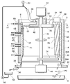
- FIG. 1 is a block diagram showing an ice machine 1 according to an embodiment of the present invention.
- the ice machine 1 has a cylindrical protective cover 2 arranged with its axes perpendicular to each other, and a cylindrical cooling drum 4 (ice making unit) arranged concentrically therein, and has an inner surface of the cooling drum 4. Ice is produced with almost the entire area of the ice making surface 4A, and the ice is crushed to produce flaky flake ice.
- a plurality of cooling drums 4 having the same diameter are arranged so as to be vertically stacked with the axes oriented vertically without any gaps, and the entire cooling drums 4 are arranged. It is covered with a protective cover 2.
- a heat insulating material (not shown) is filled between the protective cover 2 and the cooling drum 4, and the cold temperature of the cooling drum 4 is maintained.
- the cooling drum 4 is made of a metal having excellent corrosion resistance such as stainless steel, although it is not limited, and inside the peripheral wall thereof, a freezing bath 6 extending in a spiral shape coaxial with the central axis of the cooling drum 4 extends all around and a shaft. It is formed over almost the entire length in the direction.
- Each cryogen flow path 6 has an inlet 6A on the upper side and an outlet 6B on the lower side of the cooling drum 4, and when liquid carbon dioxide as a cryogen is injected from the inlet 6A, the cryogen spirals the cryogen flow path 6. It runs like a spiral and is discharged from the exit 6B. During that time, a part of the cryogen is vaporized, and the latent heat is mainly used to cool the ice making surface 4A, which is the inner peripheral surface of the cooling drum 4.
- the inlet 6A of each cryogen flow path 6 is connected to a common pipe 12 via a pressure reducing valve 7, and the pipe 12 is connected to a cryogen lead-out portion 18B via a pump 14.
- the pump 14 pressurizes liquid carbon dioxide, which is a cryogen, and supplies it to the cryogen flow path 6 through a pipe 12 and a pressure reducing valve 7, and is connected to a control unit 15 including a computer or the like, and electricity from the control unit 15.
- the discharge amount is controlled by the signal.
- Information such as the temperature and flow rate of each part of the ice machine is also transmitted to the control unit 15 of this embodiment, and the discharge amount of the pump 14 is controlled based on the control program executed by the computer.
- the operation of the control unit 15 is not limited to a computer program, but may be a manual operation in some cases, and is further controlled by an artificial intelligence program that has been machine-learned in advance. May be good.
- the control unit 15 of this embodiment is characterized in that the pump 14 is controlled so that the discharge amount of the pump 14 is 1.6 times or more the "total vaporization critical discharge amount".
- the total vaporization critical discharge amount is a parameter whose value is determined according to the performance and operating conditions of the ice maker, and is defined in the present specification as a discharge amount that exactly satisfies the following three conditions. (1) At the inlet 6A of the cryogen flow path 6, the total amount of carbon dioxide supplied is liquid. (2) Inside the cryogen flow path 6, a part of carbon dioxide is a gas and the rest is a liquid. That is, it is in a gas-liquid mixed state. (3) At the outlet 6B of the cryogen flow path 6, the entire amount of carbon dioxide becomes a gas.
- the discharge amount of the pump 14 may be controlled to be 1.6 times or more and less than 3.0 times the total vaporization critical discharge amount. In this case, since it is not necessary to increase the pressure resistance of the circulation system equipment such as the cooling drum 4, the pump 14, and the piping system so much, the cost performance including the equipment cost is good. Further, in the present embodiment, the discharge amount of the pump 14 may be controlled to be 1.6 times or more and 5 times or less of the total vaporization critical discharge amount.
- the total vaporization critical discharge amount is determined by observing the state of the cryogen flowing through the inlet 6A of the cryogen flow path 6, the inside of the cryogen flow path 6 and the outlet 6B while controlling the discharge amount of the pump 14.
- the discharge amount satisfying (1) to (3) may be determined, but it can also be obtained from the calorific value calculation as shown in Examples described later. That is, the total vaporization critical discharge amount satisfying the above conditions (1) to (3) can be obtained from the amount of ice to be produced by the cooling drum 4 and the latent heat required to produce the ice.
- the degree of superheat of the refrigerant as in the case of the CFC direct expansion type, and the degree of superheat of the cryogen can be suppressed to zero as compared with the case where the refrigerant is completely vaporized near the outlet of the refrigerant flow path.
- Uneven cooling is unlikely to occur over the entire length of the cryogen flow path 6. Therefore, the temperature distribution and cooling can be made substantially uniform over the entire area of the wide ice-making surface 4A composed of the three cooling drums 4, and the water supplied from the nozzle 50 can be distributed over the entire area of the ice-making surface 4A. Since it can be frozen with a uniform thickness, it is possible to produce flake ice P2 having a uniform thickness of ice and a uniform freezing rate, so that the quality of ice is also uniform.
- the temperature of the cryogen at the inlet 6A of the cryogen flow path 6 is preferably ⁇ 30 ° C. to ⁇ 20 ° C., and the pressure of the cryogen at the inlet 6A of the cryogen flow path 6 is 1. It is preferably 3 MPa to 1.9 MPa. More preferably, the temperature of the cryogen at the inlet 6A of the cryogen flow path 6 is ⁇ 26 ° C. to ⁇ 23 ° C., and the pressure of the cryogen at the inlet 6A of the cryogen flow path 6 is 1.5 MPa to 1.7 MPa. However, the present invention is not limited to this range.
- the outlet 6B of the cryogen flow path 6 is connected to the common pipe 10 via the temperature sensor 9, and the pipe 10 is connected to the cryogen introduction portion 18A of the evaporator 18 (heat exchanger).
- the temperature sensor 9 measures the temperature (physical quantity) of the gas-liquid mixture of the cryogen discharged from the outlet 6B, generates an electric signal corresponding to the temperature, and transmits this electric signal to the control unit 15.
- the temperature sensor 9 is also useful for measuring the degree of superheat in the cryogen flow path 6.
- the control unit 15 measures the degree of superheat of gaseous carbon dioxide in each cryogen flow path 6 in response to the signal from the temperature sensor 9, and when the degree of superheat increases, the amount of liquid carbon dioxide discharged by the pump 14 is increased and fed back. It can also be controlled to keep the degree of overheating within an acceptable range.
- the temperature sensor 9 may include a flow velocity sensor or a pressure sensor that senses the flow velocity (physical quantity) of the cryogen, and in that case, the electric output of the flow velocity sensor and / or the pressure sensor may also be transmitted to the control unit 15. Good.
- the flow velocity and / or pressure (physical quantity) measured by the flow velocity sensor and / or the pressure sensor increases, it is judged that the vaporization rate of the cold agent has increased, and the discharge amount of liquid carbon dioxide by the pump 14 is increased for feedback control. However, the degree of overheating can be suppressed to an allowable range.
- the evaporator 18 exchanges heat between the cryogen flowing from the cryogen introduction section 18A to the cryogen lead-out section 18B and the primary refrigerant flowing from the refrigerant introduction section 18D to the lead-out section 18C.
- liquid ammonia As the primary refrigerant, R404A, CO 2 and the like can be used in addition to ammonia, but ammonia is most preferable in terms of operating temperature and pressure range. Even if toxic and odorous ammonia is used as the primary refrigerant, carbon dioxide is used as the cryogen and the primary cooling side and the secondary cooling side are completely separated so that the ammonia does not affect the ice. Therefore, in the present embodiment, it is possible to safely use ammonia having good cooling efficiency.
- a part or all of the vaporized primary refrigerant after cooling the cold agent by latent heat is discharged from the lead-out unit 18C of the evaporator 18, and the primary refrigerant is introduced into the compressor 22 via the pipe 20 and is introduced into the compressor 22 by the compressor 22. After being compressed to a predetermined pressure, it is introduced from the refrigerant introduction unit 24A into the condenser 24 (primary refrigerant cooler). In the condenser 24, the pressurized and heated primary refrigerant is cooled by water or air, the cooled and liquefied primary refrigerant is discharged from the lead-out unit 24B, and evaporates from the refrigerant introduction unit 18D via the pipe 23 and the pressure reducing valve 25. Introduce to vessel 18.
- the temperature of the primary refrigerant in the refrigerant introduction section 18D of the evaporator 18 is preferably ⁇ 32 ° C. to ⁇ 22 ° C., and the pressure of the primary refrigerant in the refrigerant introduction section 18D is 0. It is preferably 006 MPa to 0.07 MPa. More preferably, the temperature of the primary refrigerant in the refrigerant introduction section 18D of the evaporator 18 is ⁇ 28 ° C. to ⁇ 25 ° C., and the pressure of the primary refrigerant in the refrigerant introduction section 18D is 0.03 MPa to 0.05 MPa. However, the present invention is not limited to this range.
- a receiver tank 16 for temporarily storing liquid carbon dioxide is provided in the pipe 19 on the upstream side of the pump 14.
- the cryogen cooled and liquefied by the evaporator 18 is introduced into the receiver tank 16 via the pipe 19.
- the cryogen liquefied by the evaporator 18 is stored in the receiver tank 16, gas-liquid separation is performed in the receiver tank 16, and only the liquid cryogen is sent to the cryogen flow path 6 using the pump 14. be able to.
- the lead-out part 16C of the receiver tank 16 is connected to the cryogen introduction part 18A of the evaporator 18 (heat exchanger) through the pipe 17, while the introduction part 16D of the receiver tank 16 is connected through the pipe 19. It is connected to the cryogen lead-out unit 18B of the evaporator 18.
- a part of the cryogen in the receiver tank 16 passes from the lead-out portion 16C through the pipe 17 and from the cryogen introduction portion 18A to the evaporator 18 and is cooled by the primary refrigerant described later.
- the cryogen cooled by the evaporator 18 enters the receiver tank 16 from the introduction section 16D via the pipe 19 from the lead-out section 18B.
- the cryogen cooled by the evaporator 18 and the cryogen returned from the cryogen flow path 6 of the cooling drum 4 are introduced into the receiver tank 16.
- gas-liquid mixed cryogen is separated into upper and lower parts in the receiver tank 16 by gravity, and only the liquid cryogen is taken out from the liquid discharge port 16B and returned to the cryogen flow path 6 via the pump 14. .. Further, a part of the gas or gas-liquid mixed cryogen in the receiver tank 16 is led out from the outlet 16C, and the cryogen is supplied from the cryogen introduction unit 18A to the evaporator 18 for cooling and liquefaction.
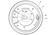
- the cooling drum 4 which is the cooling unit of the ice maker 1, and its surroundings will be described with reference to FIGS. 4 and 5. These can be applied to any of the above embodiments of FIGS. 1 to 3.
- the cooling drum 4 of this example is for continuously producing flaky flake ice P2, but the present invention is not limited to the production of flake ice, and block ice or plate ice will be described later. It can also be used in the production of ice in other shapes.
- each cooling drum 4 is vertically stacked and arranged without a gap.
- a cryogen flow path 6 having a rectangular cross section is spirally formed, and the beginning of the cryogen flow path 6
- an inlet 6A and an outlet 6B are formed.
- the inlet 6A and the outlet 6B are arranged on the same side, but may be oriented in different directions.
- a cylindrical drainage portion 30 having the same diameter and coaxial with the cooling drum 4 is attached to the lower end of the lowermost cooling drum 4, and the upper end of the inner wall surface of the drainage portion 30 is the cooling drum 4 in the radial direction. It is located at a position aligned with the ice making surface 4A, and has an inclined surface 30A that spreads outward as it goes downward. Excess water supplied to the ice making surface 4A of the cooling drum 4 and falling along the ice making surface 4A without freezing is transmitted to the inclined surface 30A of the drainage portion 30 to a position outside the ice making surface 4A of the cooling drum 4. drop down.
- An annular water receiving portion 32 is horizontally arranged below the cooling drum 4, and a water receiving wall 32A whose diameter narrows toward the upper end is formed on the inner peripheral side of the water receiving portion 32 and is inclined.
- the water falling from the surface 30A hits the water receiving wall 32A and collects in the water receiving portion 32.
- the inner bottom surface of the water receiving portion 32 is slightly inclined toward one side, the drainage port 36 is formed at the lowest position, and the drainage pipe 34 is connected to the lower surface.
- the water collected in the water receiving portion 32 flows through the drain pipe 34 through the drain port 36, is further stored in the water receiving portion 62, is pressurized by the circulation pump 60, and supplies water to the inner surface of the cooling drum 4. It is supplied to the water supply pipe 56 for the purpose. Water is also supplied to the water supply pipe 56 from a raw water supply source (not shown) via a water supply pump 58.
- a rotating shaft 40 is arranged along the central axis of the triple cooling drums 4, the upper end of the rotating shaft 40 is connected to the motor 42, and the lower end of the rotating shaft 40 is rotatably supported by the bearing 44. ..
- a disk-shaped nozzle support portion 46 is fixed horizontally and relatively non-rotatably on the upper portion of the rotating shaft 40, and a plurality of nozzle support portions 46 (three in this embodiment) are fixed from one side of the outer peripheral surface of the nozzle support portion 46.
- Nozzles 50 (but not limited to this) are mounted radially outward.
- a water flow path 48 communicating with each nozzle 50 is formed inside the nozzle support portion 46, and the upper end of the water flow path 48 opens on the upper surface of the nozzle support portion 46 as a water receiving port 48A as shown in FIG. ..
- a ring-shaped water supply portion 52 is liquidtightly arranged on the nozzle support portion 46 through the rotating shaft 40.
- the water supply unit 52 is immovable, but the rotating shaft 40 and the nozzle support unit 46 are rotatable relative to the water supply unit 52.
- a water supply channel 54 that opens on the lower surface of the water supply unit 52 is formed, and the water supply channel 54 is airtightly communicated with the water flow path 48 regardless of the rotation position of the nozzle support unit 46. There is.
- a water supply pipe 56 is connected to the water supply unit 52, and the water supplied from the water supply pipe 56 is sprayed outward from the tip of each nozzle 50 via the water supply channel 54 and the water flow path 48, and the ice making surface of the cooling drum 4 It hits 4A and runs down. In the process, the water is cooled by the cooling drum 4, and ice P1 having a constant thickness grows on the ice making surface 4A of the cooling drum 4.
- a support portion 64 and a bearing portion 66 are attached to the ends of the nozzle support portion 46 opposite to the nozzle 50, and the bearing portion 66 rotatably supports the upper end of the rotary shaft 68 of the rotary cutter 70 (crusher). Has been done.
- the lower end of the rotating shaft 68 is rotatably supported by the support arm 74, and the support arm 74 is fixed to the lower portion of the rotating shaft 40 so as not to rotate relative to each other.
- the rotary cutter 70 is arranged vertically along the ice making surface 4A of the cooling drum 4, and a plurality of loose spiral screw blades 72 are formed on the outer peripheral surface of the rotary cutter 70.
- the rotary cutter 70 rolls along the ice making surface 4A of the cooling drum 4 as the nozzle support portion 46 rotates, and the screw blade 72 has a size of about several cm on a side of the ice P1 deposited on the ice making surface 4A. Crush into flakes.
- the crushed flake ice P2 falls vertically from the ice making surface 4A of the cooling drum 4 and collects in the ice storage tank 8.
- the liquid carbon dioxide is pressurized by the pump 14, passes through the pipe 12, is distributed to the three pressure reducing valves 7 and is decompressed, and then from the inlet 6A. Enter the cryogen flow path 6 of each cooling drum 4. At the inlet 6A, almost all of carbon dioxide, which is a cryogen, is liquid. The liquid carbon dioxide spirally flows through the cryogen flow path 6 to cool the cooling drum 4, and while generating latent heat, a part of the liquid carbon dioxide is gradually vaporized.
- control unit 15 may control the pump 14 so that the discharge amount of the pump 14 is 1.6 times or more the "total vaporization critical discharge amount".
- 0.6 / 1.6 37.5% or more of the liquid carbon dioxide that has passed through the inlet 6A of the cooling drum 4 passes through the outlet 6B as a liquid.
- a relatively large amount of liquid carbon dioxide exceeding 37.5% remains until it reaches the outlet 6B of the cryogen flow path 6, so that the latent heat of the liquid carbon dioxide is mainly utilized to make the cooling drum 4 Will be cooled.
- the evaporator 18 cools the carbon dioxide of the gas or gas-liquid mixture, and the primary refrigerant of the gas or gas-liquid mixture whose temperature has risen thereby is compressed by the compressor 22 from the outlet 18C through the pipe 20, and further, the condenser 24 Will be sent to.
- the compressed and heated gas or gas-liquid mixed primary refrigerant exchanges heat with cold water or air (not shown) in the condenser 24 to become a liquid primary refrigerant, and then evaporates again through the pipe 23 and the pressure reducing valve 25. It is introduced into the vessel 18.
- Table 1 shows the appropriateness of the flow rate when the total vaporization critical discharge amount (CO 2 pump flow rate) is 9.3 L / min.
- the total vaporization critical discharge amount CO 2 pump flow rate
- there is a difference in the amount of ice making at the boundary of 9.3 (L / min) ⁇ 1.6 14.8 (L / min), which is 1.6 times or more the total vaporization critical discharge amount.
- the pump discharge amount is 15.2 L / min, which is 1.6 times or more of the total vaporization critical discharge amount
- the ice making amount is 9888 kg / day, which is less than 1.6 times 14.5 L / min.
- the amount of ice made was 8256 kg / day.
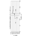
- FIG. 6 is a graph showing the relationship between the flow rate of carbon dioxide as a cryogen and the amount of ice making, and was measured under the following conditions.
- the apparatus used is the same as the embodiment shown in FIGS. 1 and 4.
- Ice making capacity 10000 kg / day
- Refrigeration capacity 53 kW (liquid carbon dioxide supply temperature: -25 ° C)
- Raw water temperature 25 ° C
- Latent heat of ice 80 kcal / kg
- Supercooling temperature 0 ° C
- Flake ice thickness 1.5 mm
- the ice making amount tends to increase discontinuously in the flow rate range which is 1.6 times the “total vaporization critical discharge amount”, and then gradually decrease. Such a tendency has not been known in the past, and a remarkable effect of the present invention has been confirmed.
- the ice maker of the present invention there is little unevenness in ice making on the ice making surface, it is possible to improve the ice production efficiency and save energy, and it is possible to produce high quality ice. It can be used industrially.
Landscapes
- Engineering & Computer Science (AREA)
- Physics & Mathematics (AREA)
- Mechanical Engineering (AREA)
- Thermal Sciences (AREA)
- General Engineering & Computer Science (AREA)
- Chemical & Material Sciences (AREA)
- Chemical Kinetics & Catalysis (AREA)
- Combustion & Propulsion (AREA)
- Production, Working, Storing, Or Distribution Of Ice (AREA)
Abstract
Priority Applications (5)
| Application Number | Priority Date | Filing Date | Title |
|---|---|---|---|
| EP20806710.8A EP3971493A4 (fr) | 2019-05-15 | 2020-05-15 | Machine de fabrication de glace |
| KR1020217036683A KR102650093B1 (ko) | 2019-05-15 | 2020-05-15 | 제빙기 |
| JP2021519498A JP7224452B2 (ja) | 2019-05-15 | 2020-05-15 | 製氷機 |
| US17/610,623 US12038216B2 (en) | 2019-05-15 | 2020-05-15 | Ice making machine |
| CN202080033943.8A CN113795717B (zh) | 2019-05-15 | 2020-05-15 | 制冰机 |
Applications Claiming Priority (2)
| Application Number | Priority Date | Filing Date | Title |
|---|---|---|---|
| JP2019092070 | 2019-05-15 | ||
| JP2019-092070 | 2019-05-15 |
Publications (1)
| Publication Number | Publication Date |
|---|---|
| WO2020230879A1 true WO2020230879A1 (fr) | 2020-11-19 |
Family
ID=73288867
Family Applications (1)
| Application Number | Title | Priority Date | Filing Date |
|---|---|---|---|
| PCT/JP2020/019392 Ceased WO2020230879A1 (fr) | 2019-05-15 | 2020-05-15 | Machine de fabrication de glace |
Country Status (6)
| Country | Link |
|---|---|
| US (1) | US12038216B2 (fr) |
| EP (1) | EP3971493A4 (fr) |
| JP (1) | JP7224452B2 (fr) |
| KR (1) | KR102650093B1 (fr) |
| CN (1) | CN113795717B (fr) |
| WO (1) | WO2020230879A1 (fr) |
Cited By (2)
| Publication number | Priority date | Publication date | Assignee | Title |
|---|---|---|---|---|
| US11683915B1 (en) | 2021-04-03 | 2023-06-20 | Nautilus True, Llc | Data center liquid conduction and carbon dioxide based cooling apparatus and method |
| US11747071B2 (en) | 2021-10-07 | 2023-09-05 | Haier Us Appliance Solutions, Inc. | Systems and methods for detecting and monitoring ice formation within an ice maker |
Citations (8)
| Publication number | Priority date | Publication date | Assignee | Title |
|---|---|---|---|---|
| JPS6215742B2 (fr) | 1982-11-16 | 1987-04-09 | Kubota Ltd | |
| JP2003314910A (ja) * | 2002-04-24 | 2003-11-06 | Matsushita Electric Ind Co Ltd | 半導体素子冷却装置およびその制御方法 |
| JP2006110416A (ja) * | 2004-10-12 | 2006-04-27 | Niigata Univ | 多段階凍結濃縮システム |
| JP2016080254A (ja) * | 2014-10-16 | 2016-05-16 | 株式会社前川製作所 | へリングボーンコイル製氷装置 |
| JP2017072358A (ja) * | 2015-10-09 | 2017-04-13 | アイスマン株式会社 | 製氷機 |
| JP2018071835A (ja) * | 2016-10-26 | 2018-05-10 | 株式会社タガワ | 製氷機 |
| JP2018159483A (ja) * | 2017-03-22 | 2018-10-11 | ホシザキ株式会社 | 流下式製氷機 |
| JP2019092070A (ja) | 2017-11-15 | 2019-06-13 | キヤノン株式会社 | 通信装置、通信システム、通信方法、及び、プログラム |
Family Cites Families (8)
| Publication number | Priority date | Publication date | Assignee | Title |
|---|---|---|---|---|
| JPS6215742U (fr) | 1985-07-12 | 1987-01-30 | ||
| JP2001201118A (ja) | 2000-01-19 | 2001-07-27 | Sumitomo Metal Ind Ltd | ハーベスト式氷蓄熱システム及び同システムの脱氷方法 |
| KR101168945B1 (ko) | 2003-11-21 | 2012-08-02 | 마에카와 매뉴팩쳐링 캄파니 리미티드 | 암모니아/co2 냉동시스템, 이 시스템에 사용되는 co2브라인 생성장치 및 이 생성장치가 포함된 암모니아 냉각유닛 |
| KR100858991B1 (ko) | 2004-09-30 | 2008-09-18 | 마에카와 매뉴팩쳐링 캄파니 리미티드 | 암모니아/co2 냉동 시스템 |
| CN2804740Y (zh) | 2005-03-18 | 2006-08-09 | 广东科龙电器股份有限公司 | 一种小型家用制冰机 |
| JP6215742B2 (ja) | 2014-03-19 | 2017-10-18 | アイスマン株式会社 | 製氷システム |
| CN204739800U (zh) | 2015-06-29 | 2015-11-04 | 中机西南能源科技有限公司 | 一种制冷系统的四管制热气脱冰结构 |
| JP6488024B2 (ja) * | 2015-11-19 | 2019-03-20 | ブランテック株式会社 | 保冷庫、移動体、氷スラリー供給システム、被保冷品輸送システム、被保冷品の保冷方法、被保冷品の輸送方法 |
-
2020
- 2020-05-15 KR KR1020217036683A patent/KR102650093B1/ko active Active
- 2020-05-15 EP EP20806710.8A patent/EP3971493A4/fr active Pending
- 2020-05-15 CN CN202080033943.8A patent/CN113795717B/zh active Active
- 2020-05-15 WO PCT/JP2020/019392 patent/WO2020230879A1/fr not_active Ceased
- 2020-05-15 US US17/610,623 patent/US12038216B2/en active Active
- 2020-05-15 JP JP2021519498A patent/JP7224452B2/ja active Active
Patent Citations (8)
| Publication number | Priority date | Publication date | Assignee | Title |
|---|---|---|---|---|
| JPS6215742B2 (fr) | 1982-11-16 | 1987-04-09 | Kubota Ltd | |
| JP2003314910A (ja) * | 2002-04-24 | 2003-11-06 | Matsushita Electric Ind Co Ltd | 半導体素子冷却装置およびその制御方法 |
| JP2006110416A (ja) * | 2004-10-12 | 2006-04-27 | Niigata Univ | 多段階凍結濃縮システム |
| JP2016080254A (ja) * | 2014-10-16 | 2016-05-16 | 株式会社前川製作所 | へリングボーンコイル製氷装置 |
| JP2017072358A (ja) * | 2015-10-09 | 2017-04-13 | アイスマン株式会社 | 製氷機 |
| JP2018071835A (ja) * | 2016-10-26 | 2018-05-10 | 株式会社タガワ | 製氷機 |
| JP2018159483A (ja) * | 2017-03-22 | 2018-10-11 | ホシザキ株式会社 | 流下式製氷機 |
| JP2019092070A (ja) | 2017-11-15 | 2019-06-13 | キヤノン株式会社 | 通信装置、通信システム、通信方法、及び、プログラム |
Cited By (3)
| Publication number | Priority date | Publication date | Assignee | Title |
|---|---|---|---|---|
| US11683915B1 (en) | 2021-04-03 | 2023-06-20 | Nautilus True, Llc | Data center liquid conduction and carbon dioxide based cooling apparatus and method |
| US12063761B1 (en) * | 2021-04-03 | 2024-08-13 | Nautilus True, Llc | Data center liquid conduction and carbon dioxide based cooling apparatus and method |
| US11747071B2 (en) | 2021-10-07 | 2023-09-05 | Haier Us Appliance Solutions, Inc. | Systems and methods for detecting and monitoring ice formation within an ice maker |
Also Published As
| Publication number | Publication date |
|---|---|
| US20220316781A1 (en) | 2022-10-06 |
| CN113795717A (zh) | 2021-12-14 |
| EP3971493A4 (fr) | 2023-01-11 |
| JP7224452B2 (ja) | 2023-02-17 |
| KR20210148344A (ko) | 2021-12-07 |
| CN113795717B (zh) | 2023-03-31 |
| US12038216B2 (en) | 2024-07-16 |
| JPWO2020230879A1 (ja) | 2021-11-25 |
| KR102650093B1 (ko) | 2024-03-22 |
| EP3971493A1 (fr) | 2022-03-23 |
Similar Documents
| Publication | Publication Date | Title |
|---|---|---|
| JP4594949B2 (ja) | 天然ガスハイドレート分解ガス及び淡水併給設備 | |
| TWI729031B (zh) | 製冰裝置、片冰製造裝置、片冰製造方法、與移動體 | |
| US12038216B2 (en) | Ice making machine | |
| CN103459324A (zh) | 用于冷冻脱盐的装置和方法 | |
| CN1971175A (zh) | 用液体制冷剂连续冷却可泵送物料的方法和装置 | |
| US6328631B1 (en) | Method and apparatus for surface processing using ice slurry | |
| CN112254388B (zh) | 生产大体积透明冰系统与方法 | |
| CN106288572B (zh) | 应用于动态冰蓄冷技术的制冰装置 | |
| CN105387653A (zh) | 蒸发器及具有其的冷水机组 | |
| AU2010257201B2 (en) | Snow making method and apparatus | |
| FR2821351A1 (fr) | Procede de recuperation d'ethane, mettant en oeuvre un cycle de refrigeration utilisant un melange d'au moins deux fluides refrigerants, gaz obtenus par ce procede, et installation de mise en oeuvre | |
| KR101502287B1 (ko) | 수평 드럼형 제빙 장치 | |
| US4704877A (en) | Apparatus and method of freezing a feed liquid | |
| JP2019148412A (ja) | 製氷機および製氷システム | |
| BR112021012764A2 (pt) | Método e instalação para esmagamento criogênico de produtos | |
| JP2007132649A (ja) | シャーベット氷製造機 | |
| JP2018132273A (ja) | アイススラリ冷却システム | |
| CN209726591U (zh) | 一种超小型片冰机蒸发器 | |
| CN105371592B (zh) | 精馏塔中无再沸器的焦炉气制取lng的方法 | |
| KR20040027578A (ko) | 튜브형 제빙장치 및 그 장치를 이용한 제빙시스템 | |
| JPH0942717A (ja) | 製氷蓄冷装置 | |
| JP2024178532A (ja) | 冷熱エネルギー利用方法および冷熱エネルギー利用装置 | |
| KR20150047236A (ko) | 즉석 아이스크림 제조장치 | |
| JPH0615243Y2 (ja) | 空調用氷蓄熱装置 | |
| US1370221A (en) | Method of ice manufacture |
Legal Events
| Date | Code | Title | Description |
|---|---|---|---|
| 121 | Ep: the epo has been informed by wipo that ep was designated in this application |
Ref document number: 20806710 Country of ref document: EP Kind code of ref document: A1 |
|
| ENP | Entry into the national phase |
Ref document number: 2021519498 Country of ref document: JP Kind code of ref document: A |
|
| ENP | Entry into the national phase |
Ref document number: 20217036683 Country of ref document: KR Kind code of ref document: A |
|
| NENP | Non-entry into the national phase |
Ref country code: DE |
|
| ENP | Entry into the national phase |
Ref document number: 2020806710 Country of ref document: EP Effective date: 20211215 |