WO2020235630A1 - Dispositif de commande de freinage - Google Patents
Dispositif de commande de freinage Download PDFInfo
- Publication number
- WO2020235630A1 WO2020235630A1 PCT/JP2020/020099 JP2020020099W WO2020235630A1 WO 2020235630 A1 WO2020235630 A1 WO 2020235630A1 JP 2020020099 W JP2020020099 W JP 2020020099W WO 2020235630 A1 WO2020235630 A1 WO 2020235630A1
- Authority
- WO
- WIPO (PCT)
- Prior art keywords
- epb
- braking
- eng
- ecu
- control device
- Prior art date
- Legal status (The legal status is an assumption and is not a legal conclusion. Google has not performed a legal analysis and makes no representation as to the accuracy of the status listed.)
- Ceased
Links
Images




Classifications
-
- B—PERFORMING OPERATIONS; TRANSPORTING
- B60—VEHICLES IN GENERAL
- B60T—VEHICLE BRAKE CONTROL SYSTEMS OR PARTS THEREOF; BRAKE CONTROL SYSTEMS OR PARTS THEREOF, IN GENERAL; ARRANGEMENT OF BRAKING ELEMENTS ON VEHICLES IN GENERAL; PORTABLE DEVICES FOR PREVENTING UNWANTED MOVEMENT OF VEHICLES; VEHICLE MODIFICATIONS TO FACILITATE COOLING OF BRAKES
- B60T13/00—Transmitting braking action from initiating means to ultimate brake actuator with power assistance or drive; Brake systems incorporating such transmitting means, e.g. air-pressure brake systems
- B60T13/74—Transmitting braking action from initiating means to ultimate brake actuator with power assistance or drive; Brake systems incorporating such transmitting means, e.g. air-pressure brake systems with electrical assistance or drive
-
- B—PERFORMING OPERATIONS; TRANSPORTING
- B60—VEHICLES IN GENERAL
- B60T—VEHICLE BRAKE CONTROL SYSTEMS OR PARTS THEREOF; BRAKE CONTROL SYSTEMS OR PARTS THEREOF, IN GENERAL; ARRANGEMENT OF BRAKING ELEMENTS ON VEHICLES IN GENERAL; PORTABLE DEVICES FOR PREVENTING UNWANTED MOVEMENT OF VEHICLES; VEHICLE MODIFICATIONS TO FACILITATE COOLING OF BRAKES
- B60T8/00—Arrangements for adjusting wheel-braking force to meet varying vehicular or ground-surface conditions, e.g. limiting or varying distribution of braking force
Definitions
- the present invention relates to a braking control device.
- the EPB controls a braking electric actuator for moving a braking member (for example, a brake pad) provided corresponding to a braked member (for example, a brake disc) that rotates integrally with a vehicle wheel, and a braking electric actuator.
- a braking member for example, a brake pad
- a braked member for example, a brake disc
- braking control device EPB-ECU (Electronic Control Unit)
- the performance of the electric braking actuator changes as the value of the usage history information (for example, the number of times of use, the current energization time, the working load amount, the total energization amount, etc.) increases. Therefore, the braking control device uses the usage history information. It is necessary to adjust the magnitude of the current input to the braking electric actuator according to the value.
- the usage history information for example, the number of times of use, the current energization time, the working load amount, the total energization amount, etc.
- the electric actuator for braking and the braking control device have been replaced. Therefore, if they are replaced due to an abnormality or the like, the value of the usage history information of the braking electric actuator stored in the braking control device is not always appropriate, and if so, it is input to the braking electric actuator. It may happen that the magnitude of the current is not adjusted correctly.
- the subject of the present invention is to recognize the value of the appropriate usage history information of the braking electric actuator and input it to the braking electric actuator even when the braking electric actuator or the braking control device constituting the EPB is replaced. It is to provide a braking control device capable of correctly adjusting the magnitude of the current.
- braking is performed by pressing the braking member toward a braking member that rotates integrally with the wheels of the vehicle, and the braking is released by separating the braking member from the braked member.
- the braking control device for an electric parking brake including a braking electric actuator and a braking control device for controlling the braking electric actuator.
- the braking control device has a storage unit that stores electric braking-related information including usage history information of the braking electric actuator as information related to the electric parking brake, and the usage history information stored in the storage unit. Based on this, a control unit for adjusting the magnitude of the current input to the braking electric actuator is provided.
- the control unit stores the electric braking-related information stored in the storage unit in another control device installed in the vehicle, and stores the electric braking-related information in the other control device at the first predetermined timing.
- the usage history information stored in the storage unit is updated based on the electric braking related information.
- FIG. 1 is a schematic view showing an overall outline of the vehicle braking device of the embodiment.
- FIG. 2 is a functional block diagram of the EPB-ECU and the ENG-ECU in the vehicle braking device of the embodiment.
- FIG. 3 is a table summarizing each item in Cases A to H of the embodiment.
- FIG. 4 is an example of a time chart in Case C of the embodiment.
- FIG. 5 is an example of a time chart in Case D of the embodiment.
- FIG. 6 is an example of a time chart in Case E of the embodiment.
- FIG. 7 is an example of a time chart in Case F of the embodiment.
- FIG. 8 is an example of a time chart in Case G of the embodiment.
- FIG. 9 is an example of a time chart in Case H of the embodiment.
- FIG. 10 is a flowchart showing the first process by the EPB-ECU of the embodiment.
- FIG. 11 is a flowchart showing a second process by the EPB-ECU of the embodiment.
- FIG. 1 is a schematic view showing an overall outline of the vehicle braking device of the embodiment.
- the vehicle braking device of the embodiment includes a service brake 1 (hydraulic braking device) and EPB2 (electric parking brake).
- the service brake 1 presses the brake pad 11 (braking member) by hydraulic pressure toward the brake disc 12 (braked member) that rotates integrally with the wheels of the vehicle based on the driver's depression of the brake pedal 3. By doing so, braking is performed (that is, service braking force (hydraulic braking force) is generated). Further, the service brake 1 releases the braking by separating the brake pad 11 from the brake disc 12.
- the pedaling force corresponding to the driver's depression of the brake pedal 3 is boosted by the booster 4, and then the brake fluid pressure corresponding to the boosted pedaling force is applied to the master cylinder ( Hereinafter referred to as M / C) 5 is generated. Then, the service braking force is generated by transmitting this brake fluid pressure to the wheel cylinder (hereinafter referred to as W / C) 6 provided in the wheel brake mechanism of each wheel. Further, an ESC (Electronic Stability Control) -ACT7, which is an actuator for controlling the brake fluid pressure, is provided between the M / C5 and the W / C6. The ESC-ACT7 adjusts the service braking force generated by the service brake 1 and performs various controls (for example, anti-skid control) for improving the safety of the vehicle.
- ESC-ACT7 Various controls using the ESC-ACT7 are executed by the EPB-ECU 8 (braking control device) that controls the service braking force.
- the EPB-ECU 8 performs both various controls using the ESC-ACT7 and various controls using the EPB-ACT20 (electric braking actuator). That is, the EPB-ECU 8 also has the function of the ESC-ECU.
- the EPB-ECU 8 outputs a control current for controlling various control valves (not shown) provided in the ESC-ACT7 and a motor for driving a pump to control the hydraulic circuit provided in the ESC-ACT7. Controls the W / C pressure transmitted to / C6. As a result, wheel slip is avoided and the safety of the vehicle is improved.
- the ESC-ACT7 controls that the brake fluid pressure generated in the M / C5 and the brake fluid pressure generated by the pump drive are applied to the W / C6 for each wheel. Equipped with a pressure boost control valve and a pressure reduction control valve that reduces the W / C pressure by supplying the brake fluid in each W / C 6 to the reservoir, the W / C pressure can be boosted, held, and reduced. It is composed. Further, the ESC-ACT7 makes it possible to realize the automatic pressurizing function of the service brake 1, and based on the pump drive and the control of various control valves, the W / C6 is automatically applied even when there is no brake operation. Can be pressurized.
- EPB2 includes EPB-ACT20, which is an operation mechanism of an electric brake including a motor 10 that generates an electric braking force by driving a wheel brake mechanism, in addition to EPB-ECU 8.
- EPB-ACT20 is an operation mechanism of an electric brake including a motor 10 that generates an electric braking force by driving a wheel brake mechanism, in addition to EPB-ECU 8.
- the EPB 2 presses the brake pads 11 by driving the motor 10 toward the brake disc 12 so that the vehicle does not move unintentionally when parking, and generates an electric braking force.
- the ENG-ECU 9 (another control device) controls the ENG 900, which is a drive device that generates a driving force on the wheels of the vehicle. Further, the ENG-ECU 9 and the EPB-ECU 8 transmit and receive information by, for example, CAN (Controller Area Network) communication.
- CAN Controller Area Network
- the wheel brake mechanism is a mechanical structure that generates a braking force in the vehicle braking device of the embodiment.
- the front wheel system wheel braking mechanism applies the service braking force by operating the service brake 1. It has a structure to generate.
- the wheel brake mechanism of the rear wheel system has a shared structure that generates a braking force for both the operation of the service brake 1 and the operation of the EPB2.
- the front wheel system wheel brake mechanism is a wheel brake mechanism that has been generally used in the past without a mechanism that generates an electric braking force based on the operation of EPB2 with respect to the rear wheel system wheel brake mechanism. Therefore, the description of the front wheel system wheel brake mechanism is omitted here, and the rear wheel system wheel brake mechanism will be described below.
- the brake pad 11 which is a friction material is pressed not only when the service brake 1 is operated but also when the EPB 2 is operated, and the brake which is a friction material is pressed by the brake pad 11.
- a frictional force is generated between the brake pad 11 and the brake disc 12, and a braking force is generated.
- the vehicle braking device of the embodiment by confirming the current detection value by the current sensor 27 that detects the current of the motor 10, the state of generation of the electric braking force by EPB2 can be confirmed and the current detection value can be recognized. You can do it.
- the front-rear G sensor 25 detects G (acceleration) in the front-rear direction (traveling direction) of the vehicle and transmits a detection signal to the EPB-ECU 8.
- the M / C pressure sensor 26 detects the M / C pressure in the M / C 5 and transmits the detection signal to the EPB-ECU 8.
- the temperature sensor 28 detects the temperature of the wheel brake mechanism (for example, the brake disc) and transmits the detection signal to the EPB-ECU 8.
- the wheel speed sensor 29 detects the rotation speed of each wheel and transmits a detection signal to the EPB-ECU 8. Although one wheel speed sensor 29 is actually provided for each wheel, detailed illustration and description thereof will be omitted here.
- the EPB-ECU 8 is composed of a well-known microcomputer equipped with a CPU, ROM, RAM, I / O, etc., and controls the brake by controlling the EPB-ACT20 including the motor 10 according to a program stored in the ROM or the like. It is something to do.
- the control of the EPB-ACT 20 will be described mainly by taking the control of the motor 10 as an example.
- the EPB-ECU 8 inputs, for example, a signal or the like corresponding to the operating state of the operation SW (switch) 23 provided on the instrument panel (not shown) in the vehicle interior, and causes the motor 10 to operate according to the operating state of the operation SW 23. Drive. Further, the EPB-ECU 8 executes lock control, release control, and the like based on the current detection value of the motor 10, and the lock control is being performed based on the control state, and the wheels are locked by the lock control. It recognizes that there is, that the release control is in progress, and that the wheel is in the release state (EPB release state) by the release control. Then, the EPB-ECU 8 outputs signals for performing various displays to the indicator lamp 24 provided on the instrument panel.
- a signal or the like corresponding to the operating state of the operation SW (switch) 23 provided on the instrument panel (not shown) in the vehicle interior, and causes the motor 10 to operate according to the operating state of the operation SW 23. Drive. Further, the EPB-ECU 8
- the service brake 1 when the vehicle is running, the service brake 1 generates the service braking force to generate the braking force in the vehicle. Further, when the vehicle is stopped by the service brake 1, the driver presses the operation SW23 to operate EPB2 to generate an electric braking force to maintain the stopped state, and then release the electric braking force. It performs the action of doing something like that. That is, as the operation of the service brake 1, when the driver operates the brake pedal 3 while the vehicle is running, the brake fluid pressure generated in the M / C 5 is transmitted to the W / C 6 to generate the service braking force. ..
- the piston is moved by driving the motor 10, and the brake pad 11 is pressed against the brake disc 12 to generate an electric braking force to lock the wheels, or the brake pad 11 is braked.
- the electric braking force is released and the wheels are released.
- the electric braking force is generated by the lock control, and the electric braking force is released by the release control.
- the EPB2 is operated by rotating the motor 10 in the forward direction, the rotation of the motor 10 is stopped at a position where the EPB2 can generate a desired electric braking force, and this state is maintained. As a result, a desired electric braking force is generated.
- the EPB2 is operated by rotating the motor 10 in the reverse direction, and the electric braking force generated by the EPB2 is released.
- EPB2 may be used as a means for generating a braking force in automatic operation.
- the performance of EPB-ACT20 changes (for example, deterioration) due to wear or the like as the value of usage history information (for example, the number of times of use, current energization time, operating load amount, total energization amount, etc.) increases.
- usage history information for example, the number of times of use, current energization time, operating load amount, total energization amount, etc.
- the EPB-ECU 8 adjusts the magnitude of the current input to the EPB-ACT 20 according to the number of times of use. That is, by changing the target current value of the motor 10 according to the number of times of use, the influence of the secular change of EPB-ACT 20 is reduced.
- EPB-ACT20 or EPB-ECU8 Even in the conventional technique, it can be recognized that an abnormality has occurred in EPB-ACT20 or EPB-ECU8. However, in the prior art, it cannot be recognized that the EPB-ACT20 or EPB-ECU8 has been replaced. For example, after the EPB2 is brought to the dealer and treated after the EPB2 abnormality occurs, it is unknown which part has been replaced.
- the number of times the EPB-ACT20 stored in the EPB-ECU8 is used is not always appropriate, and in that case, the amount of current input to the EPB-ACT20 (motor 10) is large. There may be situations where the current cannot be adjusted correctly. For example, when the EPB-ECU 8 is replaced without replacing the EPB-ACT20, if the number of times the EPB-ACT20 is used is set to 0 in the replaced EPB-ECU8 (the actual number of times of use is, for example, 10). (10,000 times), the target current value may become smaller than the appropriate value.
- the target is that the EPB-ECU8 holds the value before the replacement (for example, 100,000 times) as the number of times the EPB-ACT20 is used.
- the current value may be larger than the proper value.
- FIG. 2 is a functional block diagram of EPB-ECU 8 and ENG-ECU 9 in the vehicle braking device of the embodiment.
- the EPB-ECU 8 includes an EPB control unit 81 and an EPB storage unit 82.
- the EPB control unit 81 executes control of the EPB-ACT20 and the like.
- the EPB storage unit 82 uses the number of times (EPB), EPB-ECU abnormality history flag (EPB) (abnormal history of braking control device), EPB-ACT abnormality history flag (EPB) (electric braking actuator) as information related to EPB2. Abnormal history) (hereinafter, when these three are collectively referred to as "electric braking related information”) is stored.
- the number of times is the number of times EPB-ACT20 has been used.
- the EPB control unit 81 counts up the number of times (EPB) stored in the EPB storage unit 82. Further, the EPB control unit 81 adjusts the magnitude of the current input to the EPB-ACT 20 (motor 10) based on the number of times (EPB) stored in the EPB storage unit 82.
- the EPB-ECU abnormality history flag (EPB) is a flag for managing the abnormality history of the EPB-ECU8, and the default (initial value) is off (no abnormality occurs).
- EPB-ECU 8 detects its own abnormality, it turns on the EPB-ECU abnormality history flag (EPB).
- the EPB-ECU 8 detects its own abnormality by, for example, mutual monitoring by a microcomputer and an IC (Integrated Circuit). If an abnormality occurs in the EPB-ECU 8, there are two ways to deal with it: replacement and repair. For example, if the wiring from the EPB-ECU 8 to the motor 10 is abnormal and can be repaired immediately, the repair may be possible without replacement.
- the EPB-ACT abnormality history flag is a flag for managing the abnormality history of EPB-ACT20, and the default (initial value) is off (no abnormality occurs).
- the EPB-ACT abnormality history flag is turned on.
- the EPB-ECU 8 can detect an abnormality in the EPB-ACT 20 based on, for example, the current value of the EPB-ACT 20. Further, in the following example, if an abnormality occurs in EPB-ACT20, it is assumed that the vehicle can be restored quickly, and the countermeasure method is one of replacement.
- the ENG-ECU 9 includes an ENG control unit 91 and an ENG storage unit 92.
- the ENG control unit 91 executes control of the ENG 900 (FIG. 1) and the like.
- the ENG storage unit 92 includes the number of times (ENG), the EPB-ECU abnormality history flag (ENG), and the EPB-ACT abnormality history flag (ENG) (hereinafter, when these three are collectively referred to as "electric braking-related information").
- ENG the number of times
- ENG the EPB-ECU abnormality history flag
- ENG EPB-ACT abnormality history flag
- the number of times (ENG) corresponds to the number of times (EPB) stored in the EPB storage unit 82.
- the EPB control unit 81 updates the number of times (ENG) stored in the ENG storage unit 92 by using the number of times (EPB) stored in the EPB storage unit 82 at the second predetermined timing.
- the second predetermined timing is, for example, IG-OFF (turning off the ignition switch of the vehicle).
- the update may be performed only when the number of increases has reached a predetermined number of times (for example, 100 times). By doing so, the number of communication and storage operations can be reduced.
- the EPB-ECU abnormality history flag (ENG) corresponds to the EPB-ECU abnormality history flag (EPB) stored in the EPB storage unit 82.
- the EPB-ACT abnormality history flag (ENG) corresponds to the EPB-ACT abnormality history flag (EPB) stored in the EPB storage unit 82.
- Each of these flags is also updated by the EPB control unit 81 at the second predetermined timing, like the number of times (ENG) (details will be described later).
- the EPB control unit 81 updates the electric braking-related information stored in the EPB storage unit 82 based on the electric braking-related information stored in the ENG storage unit 92 of the ENG-ECU 9 at the first predetermined timing. ..
- the first predetermined timing is, for example, IG-ON (turning on the ignition switch of the vehicle).
- the EPB control unit 81 refers to the EPB-ACT abnormality history flag (ENG) stored in the ENG storage unit 92 of the ENG-ECU 9 at the first predetermined timing, and has an abnormality history (flag “ON”). And, when the diagnosis is normal at present, the number of times (EPB) stored in the EPB storage unit 82 is reset to 0. This is because it can be estimated that the EPB-ACT20 has been replaced because the EPB-ACT abnormality history flag (ENG) is turned on, so it is appropriate to reset the number of times (EPB) to 0. Based on.
- ENG EPB-ACT abnormality history flag
- the EPB control unit 81 refers to the electric braking related information stored in the ENG storage unit 92 of the ENG-ECU 9 at the first predetermined timing, and the EPB-ECU abnormality history flag (ENG) is turned on and If the diagnosis is normal and the EPB-ACT abnormality history flag (ENG) is off, and if the number of times (EPB) is less than the number of times (ENG), the number of times (EPB) is updated with the number of times (ENG).
- FIG. 3 is a table summarizing each item in Cases A to H of the embodiment.
- the table of FIG. 3 shows the case, the current diagnosis of EPB-ECU8 and EPB-ACT20 in EPB-ECU8, the status (EPB-ECU abnormality history flag (ENG), EPB-ACT abnormality history flag (ENG), and the number of times in order from the left. (Relationship between (EPB) and number of times (ENG)), estimated content, and treatment content.
- EPB-ECU abnormality history flag EPB
- EPB-ACT abnormality history flag EPB
- the estimated contents are the contents of estimation regarding the presence / absence of replacement of EPB-ECU8, the presence / absence of replacement of EPB-ACT20, and others.
- the action contents are the number of times (EPB), the number of times (ENG), the EPB-ECU abnormality history flag (ENG), and the action (maintenance, update (reset, etc.), clear, etc.) for the EPB-ACT abnormality history flag (ENG). Is.
- the status refers to the status (EPB-ECU abnormality history flag (ENG) status, EPB-ACT abnormality history flag (ENG) status, and the relationship between the number of times (EPB) and the number of times (ENG). ) Is shown.
- Case A is a situation (off, off, number of times (EPB) ⁇ number of times (ENG)).
- EPB off, number of times
- ENG number of times
- Case B is the situation (off, off, number of times (EPB) ⁇ number of times (ENG)).
- EPB number of times
- ENG number of times
- Case C is a situation (on, off, number of times (EPB) ⁇ number of times (ENG)).
- EPB number of times
- ENG number of times
- EPB-ACT20 since there are no abnormalities in the past and present, it can be estimated that there is no replacement. Therefore, as a treatment, both the number of times (EPB) and the number of times (ENG) do not need to be updated and may be maintained. Further, since the EPB-ECU 8 is normalized, the EPB-ECU abnormality history flag (ENG) is cleared (turned off) as a countermeasure.
- Case D is the situation (on, off, number of times (EPB) ⁇ number of times (ENG)).
- EPB number of times
- ENG number of times
- EPB-ACT20 since there are no abnormalities in the past and present, it can be estimated that there is no replacement. Therefore, as a treatment, the number of times (EPB) is updated with the number of times (ENG). Also, the number of times (ENG) may be maintained. Further, since the EPB-ECU 8 is normalized, the EPB-ECU abnormality history flag (ENG) is cleared as a measure.
- Case E is a situation (off, on, number of times (EPB) ⁇ number of times (ENG)).
- EPB number of times
- ENG number of times
- Case F is the situation (off, on, number of times (EPB) ⁇ number of times (ENG)).
- EPB number of times
- ENG number of times
- the EPB-ACT20 since the EPB-ACT20 has been replaced, the number of times (EPB) and the number of times (ENG) are reset to 0. Since the number of times (EPB) ⁇ number of times (ENG) is not normal, it can be estimated that there was a forced operation as in case B, but the number of times (EPB) and the number of times (ENG) are reset to 0, so the problem is There is no. Further, since the EPB-ACT20 has been replaced, the EPB-ACT abnormality history flag (ENG) is cleared as a measure.
- Case G is a situation (on, on, number of times (EPB) ⁇ number of times (ENG)).
- EPB number of times
- ENG number of times
- Case H is the situation (on, on, number of times (EPB) ⁇ number of times (ENG)).
- EPB number of times
- ENG number of times
- the number of times (EPB) is maintained at 0 because the EPB-ECU 8 is replaced and set to 0, and the number of times (ENG) is reset to 0. Further, since the EPB-ECU 8 and the EPB-ACT20 are exchanged, both the EPB-ECU abnormality history flag (ENG) and the EPB-ACT abnormality history flag (ENG) are cleared as a measure.
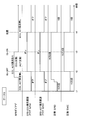
- FIG. 4 is an example of a time chart in Case C of the embodiment.
- the horizontal axis is time, and EPB diagnostics (EPB-ECU abnormality history flag (EPB) and EPB-ACT abnormality history flag (EPB)) and EPB-ECU abnormality history flag (EPB-ECU abnormality history flag (EPB)) are arranged in order from the top.
- EPB diagnostics EPB-ECU abnormality history flag (EPB) and EPB-ACT abnormality history flag (EPB)
- EPB-ECU abnormality history flag (EPB) EPB-ECU abnormality history flag (EPB)
- the timing at which the electric braking related information is sent from the EPB-ECU 8 to the ENG-ECU 9 is set to the time t2 when the IG-OFF occurs. Further, the timing at which the treatment is performed is set to the time t4 immediately after the time t3 when the IG-ON is set.
- each state is, in order from the top, ECU (EPB-ECU8), ACT (EPB-ACT20) no abnormality, off, off, 100,000 times, 100,000 times. Then, it is assumed that an abnormality has occurred in the EPB-ECU 8 between the time t1 and the time t2. In that case, at time t2, the EPB-ECU 8 sends a notification to that effect to the ENG-ECU 9, and the EPB-ECU abnormality history flag (ENG) is turned on. Further, it is assumed that the number of times (EPB) increases twice between the time t1 and the time t2 to 102 times. In that case, at time t2, the number of times (ENG) is updated to 102 times.
- EPB-ACT20 since there are no abnormalities in the past and present, it can be estimated that there is no replacement. Therefore, at time t4, it is not necessary to update both the number of times (EPB) and the number of times (ENG) as the treatment, and 102 times are maintained. Further, since the EPB-ECU 8 is normalized, the EPB-ECU abnormality history flag (ENG) is cleared (turned off) as a countermeasure.
- FIG. 5 is an example of a time chart in Case D of the embodiment. The same matters as in FIG. 4 will be omitted (the same applies to the explanations in FIGS. 6 to 9). 5 is different from the case of FIG. 4 in that the EPB-ECU 8 is normalized by replacement rather than repair between time t2 and time t3.
- the EPB diagnostic has no ECU or ACT abnormality.
- the number of times (EPB) becomes 0. Since the number of times (EPB) (0,000 times) ⁇ number of times (ENG) (100,000 times), it can be estimated that the EPB-ECU 8 has been replaced. Therefore, at time t4, as a measure, the number of times (EPB) is updated with the number of times (ENG) to be 102 times.
- FIG. 6 is an example of a time chart in Case E of the embodiment.
- FIG. 6 is different from the case of FIG. 4 in that an abnormality occurs in EPB-ACT20 instead of EPB-ECU8 between time t1 and time t2.
- the EPB-ACT abnormality history flag (ENG) is updated from off to on at time t2. Further, if the EPB-ACT20 is replaced by the time t3, the EPB diagnosis becomes no ECU and ACT abnormality at the time t3.
- the number of times (EPB) (102 times) the number of times (ENG) (102 times) is normal. Further, as a treatment, since the EPB-ACT20 has been replaced, the number of times (EPB) and the number of times (ENG) are reset to 0. Further, since the EPB-ACT20 has been replaced, the EPB-ACT abnormality history flag (ENG) is cleared as a measure.
- FIG. 7 is an example of a time chart in Case F of the embodiment. 7 is different from the case of FIG. 6 in that the number of times (EPB) is updated to 50,000 times by a forced operation shortly before the time t2. Since the number of times (EPB) (50,000 times) ⁇ number of times (ENG) (102,000 times) is not normal, it can be estimated that there was a forced operation, but the number of times (EPB) and the number of times (ENG) are set to 0. There is no problem because it resets.
- EPB number of times
- ENG number of times
- FIG. 8 is an example of a time chart in Case G of the embodiment. It is assumed that an abnormality has occurred in both the EPB-ECU 8 and the EPB-ACT 20 between the time t1 and the time t2. In that case, at time t2, the EPB-ECU 8 sends a notification to that effect to the ENG-ECU 9, and the EPB-ECU abnormality history flag (ENG) and the EPB-ACT abnormality history flag (ENG) are turned on. Further, it is assumed that the EPB-ECU 8 has been repaired and normalized by the time t3, and the EPB-ACT 20 has been replaced.
- ENG EPB-ECU abnormality history flag
- ENG EPB-ACT abnormality history flag
- EPB-ACT20 is exchanged, so the number of times (EPB) and the number of times (ENG) are reset to 0. Further, since both EPB-ECU8 and EPB-ACT20 are normalized, both the EPB-ECU abnormality history flag (ENG) and the EPB-ACT abnormality history flag (ENG) are cleared as a measure.
- FIG. 9 is an example of a time chart in Case H of the embodiment. 9 is different from the case of FIG. 8 in that the EPB-ECU 8 is normalized by replacement rather than repair between time t2 and time t3.
- the EPB diagnostic has no ECU or ACT abnormality.
- the number of times (EPB) becomes 0. Since the number of times (EPB) (0,000 times) ⁇ number of times (ENG) (100,000 times), it can be estimated that the EPB-ECU 8 has been replaced.
- the EPB-ACT20 since the EPB-ACT20 was replaced, the number of times (EPB) is maintained at 0 and the number of times (ENG) is reset to 0 as a measure at time t4.
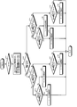
- FIG. 10 is a flowchart showing the first process by the EPB-ECU 8 of the embodiment.
- the vehicle is in the IG-ON state at the start of the first process.
- step S1 the EPB control unit 81 of the EPB-ECU 8 determines whether or not the EPB-ACT20 has been activated, and if Yes, proceeds to step S2, and if No, proceeds to step S3.
- step S2 the EPB control unit 81 counts up the number of times (EPB) in the EPB storage unit 82.
- step S3 the EPB control unit 81 determines whether or not an abnormality has occurred in the EPB-ECU 8, and if Yes, proceeds to step S4, and if No, proceeds to step S5.
- step S4 the EPB-ECU 8 turns on the EPB-ECU abnormality history flag (EPB) of the EPB storage unit 82.
- EPB EPB-ECU abnormality history flag
- step S5 the EPB control unit 81 determines whether or not an abnormality has occurred in EPB-ACT20, and if Yes, proceeds to step S6, and if No, proceeds to step S7.
- step S6 the EPB control unit 81 turns on the EPB-ACT abnormality history flag (EPB) of the EPB storage unit 82.
- EPB EPB-ACT abnormality history flag
- step S7 the EPB control unit 81 determines whether or not the IG-OFF has been turned on, and if Yes, the process proceeds to step S8, and if No, the process returns to step S1.
- step S8 the EPB control unit 81 uses the number of times (EPB) stored in the EPB storage unit 82, the EPB-ECU abnormality history flag (EPB), and the EPB-ACT abnormality history flag (EPB) to ENG, respectively.
- EPB number of times
- ENG the number of times stored in the ENG storage unit 92 of the ECU 9
- ENG the EPB-ECU abnormality history flag
- ENG the EPB-ACT abnormality history flag
- the number of times (EPB) is counted up, and the EPB-ECU abnormality history flag (EPB) and EPB-ACT abnormality history flag (EPB) are set as necessary. It can be turned on. Further, when the vehicle shifts to the IG-OFF state, the electric braking stored in the ENG storage unit 92 of the ENG-ECU 9 is used by using the electric braking related information stored in the EPB storage unit 82 of the EPB-ECU 8. Relationship information can be updated.
- FIG. 11 is a flowchart showing a second process by the EPB-ECU 8 of the embodiment.
- the vehicle is in the IG-OFF state at the start of the second process.
- step S11 the EPB control unit 81 of the EPB-ECU 8 determines whether or not the IG-ON has been turned on. If Yes, the process proceeds to Step S12, and if No, the process returns to Step S11.
- step S12 the EPB control unit 81 reads out the number of times (ENG) stored in the ENG storage unit 92 of the ENG-ECU 9, the EPB-ECU abnormality history flag (ENG), and the EPB-ACT abnormality history flag (ENG).
- ENG the number of times stored in the ENG storage unit 92 of the ENG-ECU 9
- ENG the EPB-ECU abnormality history flag
- ENG the EPB-ACT abnormality history flag
- step S13 the EPB control unit 81 determines whether or not the number of times (EPB) ⁇ the number of times (ENG), and if Yes, the process proceeds to step S14, and if No, the process proceeds to step S15.
- step S14 the EPB control unit 81 determines whether or not the EPB-ECU abnormality history flag (ENG) is on, and if Yes, proceeds to step S16, and if No, proceeds to step S17.
- ENG EPB-ECU abnormality history flag
- step S16 the EPB control unit 81 determines whether or not the EPB-ACT abnormality history flag (ENG) is on, and if Yes, proceeds to step S20, and if No, proceeds to step S21.
- ENG EPB-ACT abnormality history flag
- step S20 the EPB control unit 81 executes the treatment of case G (see FIG. 3).
- step S21 the EPB control unit 81 executes the procedure of case C (see FIG. 3).
- step S17 the EPB control unit 81 determines whether or not the EPB-ACT abnormality history flag (ENG) is on. If Yes, the process proceeds to Step S22, and if No (Case A), the process ends.
- ENG EPB-ACT abnormality history flag
- step S22 the EPB control unit 81 executes the procedure of case E (see FIG. 3).
- step S18 the EPB control unit 81 determines whether or not the EPB-ACT abnormality history flag (ENG) is on, and if Yes, proceeds to step S23, and if No, proceeds to step S24.
- ENG EPB-ACT abnormality history flag
- step S23 the EPB control unit 81 executes the treatment of case H (see FIG. 3).
- step S24 the EPB control unit 81 executes the procedure of case D (see FIG. 3).
- step S19 the EPB control unit 81 determines whether or not the EPB-ACT abnormality history flag (ENG) is on, proceeds to step S25 if Yes, and ends the process if No (Case B).
- ENG EPB-ACT abnormality history flag
- step S25 the EPB control unit 81 executes the treatment of case F (see FIG. 3).
- the electric braking-related information in the EPB storage unit 82 is updated at any time, and the electric braking-related information in the ENG storage unit 92 of the ENG-ECU 9 is updated as appropriate. Even when the ENG-ECU 9 or EPB-ECU 8 is replaced, it is possible to recognize the appropriate number of times the ENG-ECU 9 has been used and correctly adjust the magnitude of the current input to the ENG-ECU 9.
- the EPB control unit 81 of the EPB-ECU 8 refers to the ENG storage unit 92 of the ENG-ECU 9 at the first predetermined timing such as IG-ON, and the EPB-ACT abnormality history flag (ENG) is turned on.
- the magnitude of the current input to the ENG-ECU 9 can be correctly adjusted by resetting the number of times (EPB) stored in the EPB storage unit 82 to 0.
- the EPB control unit 81 refers to the ENG storage unit 92 of the ENG-ECU 9 at the first predetermined timing such as IG-ON, the EPB-ECU abnormality history flag (ENG) is turned on, and the EPB-ACT When the abnormality history flag (ENG) is off and the number of times (EPB) ⁇ number of times (ENG) (case D), the number of times (EPB) is updated by the number of times (ENG) and input to the ENG-ECU 9. The magnitude of the current can be adjusted correctly.
- the EPB control unit 81 has the number of times (EPB) stored in the EPB storage unit 82 and the EPB-ECU abnormality history flag (EPB) at the second predetermined timing such as when the vehicle is in the IG-OFF state. ), EPB-ACT abnormality history flag (EPB), the number of times (ENG) stored in the ENG storage unit 92 of the ENG-ECU 9, EPB-ECU abnormality history flag (ENG), EPB-ACT abnormality history, respectively. Update the flag (ENG). As a result, the number of communications between the EPB-ECU 8 and the ENG-ECU 9 and the number of storage operations in the ENG-ECU 9 can be reduced as compared with the case where such an update is performed at any time. However, it does not limit updates from time to time.
- the ability to accurately recognize the number of times EPB-ACT20 has been used has the following effects. First, it is not necessary to pass an unnecessary current through the EPB-ACT20. Further, since the EPB-ACT 20 does not generate an unnecessary axial force, it is not necessary to apply an excessive load to the caliper 13, and the life can be extended. Further, since the operating time of EPB-ACT20 can be optimized, it is possible to avoid the generation of unnecessary operating noise. In addition, the release operation time of EPB-ACT20 can be shortened, and the responsiveness can be improved.
- the number of times of use has been described as an example of usage history information, but the present invention is not limited to this, and the same applies to the current energization time, operating load amount, total energization amount, and the like.
- the wheel to be braked by EPB2 is not limited to the rear wheel, but may be the front wheel. Further, the number of wheels of the vehicle subject to the present invention is not limited to four wheels, and may be six or more.
- the present invention may be applied to each EPB. Further, if the number of other ECUs is increased, the reliability can be further improved.
Landscapes
- Engineering & Computer Science (AREA)
- Transportation (AREA)
- Mechanical Engineering (AREA)
- Braking Systems And Boosters (AREA)
- Regulating Braking Force (AREA)
- Valves And Accessory Devices For Braking Systems (AREA)
Abstract
La présente invention concerne un dispositif de commande de freinage pour un frein de stationnement électrique qui comprend un actionneur électrique de freinage et ledit dispositif de commande de freinage. Le dispositif de commande de freinage comprend : une unité de stockage pour stocker des informations relatives au freinage électrique comprenant des informations d'historique d'utilisation de l'actionneur électrique de freinage, en tant qu'informations relatives au frein de stationnement électrique ; et une unité de commande pour ajuster l'amplitude d'une entrée de courant dans l'actionneur électrique de freinage, sur la base des informations d'historique d'utilisation stockées dans l'unité de stockage. L'unité de commande amène les informations relatives au freinage électrique stockées dans l'unité de stockage à être stockées dans un autre dispositif de commande installé dans un véhicule, et met à jour les informations d'historique d'utilisation stockées dans l'unité de stockage, sur la base des informations relatives au freinage électrique stockées dans l'autre dispositif de commande.
Applications Claiming Priority (2)
| Application Number | Priority Date | Filing Date | Title |
|---|---|---|---|
| JP2019-096816 | 2019-05-23 | ||
| JP2019096816A JP7310299B2 (ja) | 2019-05-23 | 2019-05-23 | 制動制御装置 |
Publications (1)
| Publication Number | Publication Date |
|---|---|
| WO2020235630A1 true WO2020235630A1 (fr) | 2020-11-26 |
Family
ID=73454896
Family Applications (1)
| Application Number | Title | Priority Date | Filing Date |
|---|---|---|---|
| PCT/JP2020/020099 Ceased WO2020235630A1 (fr) | 2019-05-23 | 2020-05-21 | Dispositif de commande de freinage |
Country Status (2)
| Country | Link |
|---|---|
| JP (1) | JP7310299B2 (fr) |
| WO (1) | WO2020235630A1 (fr) |
Cited By (4)
| Publication number | Priority date | Publication date | Assignee | Title |
|---|---|---|---|---|
| CN114701460A (zh) * | 2022-04-12 | 2022-07-05 | 中国第一汽车股份有限公司 | 电子驻车系统的上下电管理方法、装置、车辆及存储介质 |
| US20230106755A1 (en) * | 2021-10-01 | 2023-04-06 | Ford Global Technologies, Llc | Methods and apparatus to extend brake life cycle |
| US20240149844A1 (en) * | 2019-10-31 | 2024-05-09 | Mando Corporation | Electronic parking brake system and control method therefor |
| CN120156483A (zh) * | 2025-05-20 | 2025-06-17 | 北京少仕科技有限公司 | 一种行车制动装置及制动系统 |
Citations (2)
| Publication number | Priority date | Publication date | Assignee | Title |
|---|---|---|---|---|
| US20160347299A1 (en) * | 2015-05-26 | 2016-12-01 | Mando Corporation | Electronic parking brake epb system and method of controlling the same |
| US20180215355A1 (en) * | 2017-02-02 | 2018-08-02 | Lucas Automotive Gmbh | System, Method, Computer Program and Control Unit for Preventing a Vehicle from Rolling Away |
-
2019
- 2019-05-23 JP JP2019096816A patent/JP7310299B2/ja active Active
-
2020
- 2020-05-21 WO PCT/JP2020/020099 patent/WO2020235630A1/fr not_active Ceased
Patent Citations (2)
| Publication number | Priority date | Publication date | Assignee | Title |
|---|---|---|---|---|
| US20160347299A1 (en) * | 2015-05-26 | 2016-12-01 | Mando Corporation | Electronic parking brake epb system and method of controlling the same |
| US20180215355A1 (en) * | 2017-02-02 | 2018-08-02 | Lucas Automotive Gmbh | System, Method, Computer Program and Control Unit for Preventing a Vehicle from Rolling Away |
Cited By (6)
| Publication number | Priority date | Publication date | Assignee | Title |
|---|---|---|---|---|
| US20240149844A1 (en) * | 2019-10-31 | 2024-05-09 | Mando Corporation | Electronic parking brake system and control method therefor |
| US12227158B2 (en) * | 2019-10-31 | 2025-02-18 | Hl Mando Corporation | Electronic parking brake system and control method therefor |
| US20230106755A1 (en) * | 2021-10-01 | 2023-04-06 | Ford Global Technologies, Llc | Methods and apparatus to extend brake life cycle |
| US12227157B2 (en) * | 2021-10-01 | 2025-02-18 | Ford Global Technologies, Llc | Methods and apparatus to extend brake life cycle |
| CN114701460A (zh) * | 2022-04-12 | 2022-07-05 | 中国第一汽车股份有限公司 | 电子驻车系统的上下电管理方法、装置、车辆及存储介质 |
| CN120156483A (zh) * | 2025-05-20 | 2025-06-17 | 北京少仕科技有限公司 | 一种行车制动装置及制动系统 |
Also Published As
| Publication number | Publication date |
|---|---|
| JP7310299B2 (ja) | 2023-07-19 |
| JP2020189593A (ja) | 2020-11-26 |
Similar Documents
| Publication | Publication Date | Title |
|---|---|---|
| WO2020235630A1 (fr) | Dispositif de commande de freinage | |
| US8645003B2 (en) | Braking control system and method for vehicle | |
| KR102481911B1 (ko) | 전기식 주차 브레이크용 모터 차량 제어유닛 | |
| CN112739593B (zh) | 汽车的驻车制动系统、汽车及其控制方法 | |
| EP3000674B1 (fr) | Système de support de frein électronique destiné à être utilisé lorsque le système de frein de service a échoué ou est dégradé | |
| KR101512869B1 (ko) | 조합형 제동 시스템 | |
| CN113306541B (zh) | 可电驱动汽车的安全系统、运行该安全系统的方法和汽车 | |
| KR102113933B1 (ko) | 브레이크 시스템 및 브레이크 시스템을 작동시키기 위한 방법 | |
| JP5254334B2 (ja) | 車両用ブレーキ装置および車両用ブレーキ装置の作動方法 | |
| KR102197473B1 (ko) | 차량 브레이크 시스템의 하나 이상의 전기 주차 브레이크용 제어 장치, 그리고 브레이크 부스터 및 전기 주차 브레이크를 포함하는 차량 브레이크 시스템의 작동 방법 | |
| US20200055506A1 (en) | System comprising separate control units for the actuation units of an electric parking brake | |
| US8676462B2 (en) | Electronic brake system having a friction brake comprising friction linings for at least one wheel brake, and having at least one electronic control device | |
| CN103889782B (zh) | 用于控制机动车中的制动灯的装置 | |
| CN1989034A (zh) | 用于具有电动驻车制动装置的车辆的制动设备和用于控制该制动设备的方法 | |
| KR102507676B1 (ko) | 자동차용 브레이크 시스템 | |
| JP6873282B2 (ja) | 完全統合制動システムにおける電子パーキングブレーキを使用した補助減速 | |
| JP7239709B2 (ja) | 車両の電動制動および電動操舵のための制御アーキテクチャおよび当該制御アーキテクチャの制御方法 | |
| KR20240149638A (ko) | 전자식 주차 브레이크를 이용한 긴급 제동 시스템 및 긴급 제동 방법 | |
| CN113825685A (zh) | 具有复合管理功能的车辆制动系统 | |
| CN108367747B (zh) | 用于控制能够执行泊车制动功能的制动系统的方法 | |
| JP2016159829A (ja) | 車両のブレーキ装置 | |
| CN113619548A (zh) | 用于运行驻车制动系统的方法和装置 | |
| JP6626365B2 (ja) | 駐車ブレーキ制御装置 | |
| US20230265900A1 (en) | Brake system and method for controlling the same | |
| US20230023343A1 (en) | Test arrangement for functional testing of a vehicle brake control system |
Legal Events
| Date | Code | Title | Description |
|---|---|---|---|
| 121 | Ep: the epo has been informed by wipo that ep was designated in this application |
Ref document number: 20809068 Country of ref document: EP Kind code of ref document: A1 |
|
| NENP | Non-entry into the national phase |
Ref country code: DE |
|
| 122 | Ep: pct application non-entry in european phase |
Ref document number: 20809068 Country of ref document: EP Kind code of ref document: A1 |