WO2020235638A1 - 多孔炭素構造体、その製造方法、それを用いた正極材及びそれを用いた電池 - Google Patents
多孔炭素構造体、その製造方法、それを用いた正極材及びそれを用いた電池 Download PDFInfo
- Publication number
- WO2020235638A1 WO2020235638A1 PCT/JP2020/020143 JP2020020143W WO2020235638A1 WO 2020235638 A1 WO2020235638 A1 WO 2020235638A1 JP 2020020143 W JP2020020143 W JP 2020020143W WO 2020235638 A1 WO2020235638 A1 WO 2020235638A1
- Authority
- WO
- WIPO (PCT)
- Prior art keywords
- porous carbon
- carbon structure
- less
- range
- positive electrode
- Prior art date
- Legal status (The legal status is an assumption and is not a legal conclusion. Google has not performed a legal analysis and makes no representation as to the accuracy of the status listed.)
- Ceased
Links
Images


Classifications
-
- C—CHEMISTRY; METALLURGY
- C01—INORGANIC CHEMISTRY
- C01B—NON-METALLIC ELEMENTS; COMPOUNDS THEREOF; METALLOIDS OR COMPOUNDS THEREOF NOT COVERED BY SUBCLASS C01C
- C01B32/00—Carbon; Compounds thereof
- C01B32/05—Preparation or purification of carbon not covered by groups C01B32/15, C01B32/20, C01B32/25, C01B32/30
-
- H—ELECTRICITY
- H01—ELECTRIC ELEMENTS
- H01M—PROCESSES OR MEANS, e.g. BATTERIES, FOR THE DIRECT CONVERSION OF CHEMICAL ENERGY INTO ELECTRICAL ENERGY
- H01M4/00—Electrodes
- H01M4/86—Inert electrodes with catalytic activity, e.g. for fuel cells
- H01M4/8605—Porous electrodes
-
- C—CHEMISTRY; METALLURGY
- C04—CEMENTS; CONCRETE; ARTIFICIAL STONE; CERAMICS; REFRACTORIES
- C04B—LIME, MAGNESIA; SLAG; CEMENTS; COMPOSITIONS THEREOF, e.g. MORTARS, CONCRETE OR LIKE BUILDING MATERIALS; ARTIFICIAL STONE; CERAMICS; REFRACTORIES; TREATMENT OF NATURAL STONE
- C04B35/00—Shaped ceramic products characterised by their composition; Ceramics compositions; Processing powders of inorganic compounds preparatory to the manufacturing of ceramic products
- C04B35/515—Shaped ceramic products characterised by their composition; Ceramics compositions; Processing powders of inorganic compounds preparatory to the manufacturing of ceramic products based on non-oxide ceramics
- C04B35/52—Shaped ceramic products characterised by their composition; Ceramics compositions; Processing powders of inorganic compounds preparatory to the manufacturing of ceramic products based on non-oxide ceramics based on carbon, e.g. graphite
- C04B35/528—Shaped ceramic products characterised by their composition; Ceramics compositions; Processing powders of inorganic compounds preparatory to the manufacturing of ceramic products based on non-oxide ceramics based on carbon, e.g. graphite obtained from carbonaceous particles with or without other non-organic components
- C04B35/532—Shaped ceramic products characterised by their composition; Ceramics compositions; Processing powders of inorganic compounds preparatory to the manufacturing of ceramic products based on non-oxide ceramics based on carbon, e.g. graphite obtained from carbonaceous particles with or without other non-organic components containing a carbonisable binder
-
- C—CHEMISTRY; METALLURGY
- C04—CEMENTS; CONCRETE; ARTIFICIAL STONE; CERAMICS; REFRACTORIES
- C04B—LIME, MAGNESIA; SLAG; CEMENTS; COMPOSITIONS THEREOF, e.g. MORTARS, CONCRETE OR LIKE BUILDING MATERIALS; ARTIFICIAL STONE; CERAMICS; REFRACTORIES; TREATMENT OF NATURAL STONE
- C04B35/00—Shaped ceramic products characterised by their composition; Ceramics compositions; Processing powders of inorganic compounds preparatory to the manufacturing of ceramic products
- C04B35/622—Forming processes; Processing powders of inorganic compounds preparatory to the manufacturing of ceramic products
- C04B35/626—Preparing or treating the powders individually or as batches ; preparing or treating macroscopic reinforcing agents for ceramic products, e.g. fibres; mechanical aspects section B
- C04B35/62605—Treating the starting powders individually or as mixtures
- C04B35/62625—Wet mixtures
- C04B35/6263—Wet mixtures characterised by their solids loadings, i.e. the percentage of solids
-
- C—CHEMISTRY; METALLURGY
- C04—CEMENTS; CONCRETE; ARTIFICIAL STONE; CERAMICS; REFRACTORIES
- C04B—LIME, MAGNESIA; SLAG; CEMENTS; COMPOSITIONS THEREOF, e.g. MORTARS, CONCRETE OR LIKE BUILDING MATERIALS; ARTIFICIAL STONE; CERAMICS; REFRACTORIES; TREATMENT OF NATURAL STONE
- C04B35/00—Shaped ceramic products characterised by their composition; Ceramics compositions; Processing powders of inorganic compounds preparatory to the manufacturing of ceramic products
- C04B35/622—Forming processes; Processing powders of inorganic compounds preparatory to the manufacturing of ceramic products
- C04B35/626—Preparing or treating the powders individually or as batches ; preparing or treating macroscopic reinforcing agents for ceramic products, e.g. fibres; mechanical aspects section B
- C04B35/62605—Treating the starting powders individually or as mixtures
- C04B35/62625—Wet mixtures
- C04B35/6264—Mixing media, e.g. organic solvents
-
- C—CHEMISTRY; METALLURGY
- C04—CEMENTS; CONCRETE; ARTIFICIAL STONE; CERAMICS; REFRACTORIES
- C04B—LIME, MAGNESIA; SLAG; CEMENTS; COMPOSITIONS THEREOF, e.g. MORTARS, CONCRETE OR LIKE BUILDING MATERIALS; ARTIFICIAL STONE; CERAMICS; REFRACTORIES; TREATMENT OF NATURAL STONE
- C04B35/00—Shaped ceramic products characterised by their composition; Ceramics compositions; Processing powders of inorganic compounds preparatory to the manufacturing of ceramic products
- C04B35/622—Forming processes; Processing powders of inorganic compounds preparatory to the manufacturing of ceramic products
- C04B35/626—Preparing or treating the powders individually or as batches ; preparing or treating macroscopic reinforcing agents for ceramic products, e.g. fibres; mechanical aspects section B
- C04B35/63—Preparing or treating the powders individually or as batches ; preparing or treating macroscopic reinforcing agents for ceramic products, e.g. fibres; mechanical aspects section B using additives specially adapted for forming the products, e.g.. binder binders
- C04B35/632—Organic additives
- C04B35/634—Polymers
- C04B35/63404—Polymers obtained by reactions only involving carbon-to-carbon unsaturated bonds
- C04B35/6344—Copolymers containing at least three different monomers
-
- C—CHEMISTRY; METALLURGY
- C04—CEMENTS; CONCRETE; ARTIFICIAL STONE; CERAMICS; REFRACTORIES
- C04B—LIME, MAGNESIA; SLAG; CEMENTS; COMPOSITIONS THEREOF, e.g. MORTARS, CONCRETE OR LIKE BUILDING MATERIALS; ARTIFICIAL STONE; CERAMICS; REFRACTORIES; TREATMENT OF NATURAL STONE
- C04B35/00—Shaped ceramic products characterised by their composition; Ceramics compositions; Processing powders of inorganic compounds preparatory to the manufacturing of ceramic products
- C04B35/71—Ceramic products containing macroscopic reinforcing agents
- C04B35/78—Ceramic products containing macroscopic reinforcing agents containing non-metallic materials
- C04B35/80—Fibres, filaments, whiskers, platelets, or the like
- C04B35/83—Carbon fibres in a carbon matrix
-
- C—CHEMISTRY; METALLURGY
- C04—CEMENTS; CONCRETE; ARTIFICIAL STONE; CERAMICS; REFRACTORIES
- C04B—LIME, MAGNESIA; SLAG; CEMENTS; COMPOSITIONS THEREOF, e.g. MORTARS, CONCRETE OR LIKE BUILDING MATERIALS; ARTIFICIAL STONE; CERAMICS; REFRACTORIES; TREATMENT OF NATURAL STONE
- C04B38/00—Porous mortars, concrete, artificial stone or ceramic ware; Preparation thereof
- C04B38/08—Porous mortars, concrete, artificial stone or ceramic ware; Preparation thereof by adding porous substances
-
- H—ELECTRICITY
- H01—ELECTRIC ELEMENTS
- H01M—PROCESSES OR MEANS, e.g. BATTERIES, FOR THE DIRECT CONVERSION OF CHEMICAL ENERGY INTO ELECTRICAL ENERGY
- H01M12/00—Hybrid cells; Manufacture thereof
- H01M12/04—Hybrid cells; Manufacture thereof composed of a half-cell of the fuel-cell type and of a half-cell of the primary-cell type
- H01M12/06—Hybrid cells; Manufacture thereof composed of a half-cell of the fuel-cell type and of a half-cell of the primary-cell type with one metallic and one gaseous electrode
-
- H—ELECTRICITY
- H01—ELECTRIC ELEMENTS
- H01M—PROCESSES OR MEANS, e.g. BATTERIES, FOR THE DIRECT CONVERSION OF CHEMICAL ENERGY INTO ELECTRICAL ENERGY
- H01M12/00—Hybrid cells; Manufacture thereof
- H01M12/08—Hybrid cells; Manufacture thereof composed of a half-cell of a fuel-cell type and a half-cell of the secondary-cell type
-
- H—ELECTRICITY
- H01—ELECTRIC ELEMENTS
- H01M—PROCESSES OR MEANS, e.g. BATTERIES, FOR THE DIRECT CONVERSION OF CHEMICAL ENERGY INTO ELECTRICAL ENERGY
- H01M4/00—Electrodes
- H01M4/86—Inert electrodes with catalytic activity, e.g. for fuel cells
- H01M4/88—Processes of manufacture
-
- H—ELECTRICITY
- H01—ELECTRIC ELEMENTS
- H01M—PROCESSES OR MEANS, e.g. BATTERIES, FOR THE DIRECT CONVERSION OF CHEMICAL ENERGY INTO ELECTRICAL ENERGY
- H01M4/00—Electrodes
- H01M4/86—Inert electrodes with catalytic activity, e.g. for fuel cells
- H01M4/88—Processes of manufacture
- H01M4/8878—Treatment steps after deposition of the catalytic active composition or after shaping of the electrode being free-standing body
- H01M4/8882—Heat treatment, e.g. drying, baking
-
- H—ELECTRICITY
- H01—ELECTRIC ELEMENTS
- H01M—PROCESSES OR MEANS, e.g. BATTERIES, FOR THE DIRECT CONVERSION OF CHEMICAL ENERGY INTO ELECTRICAL ENERGY
- H01M4/00—Electrodes
- H01M4/86—Inert electrodes with catalytic activity, e.g. for fuel cells
- H01M4/96—Carbon-based electrodes
-
- C—CHEMISTRY; METALLURGY
- C01—INORGANIC CHEMISTRY
- C01P—INDEXING SCHEME RELATING TO STRUCTURAL AND PHYSICAL ASPECTS OF SOLID INORGANIC COMPOUNDS
- C01P2006/00—Physical properties of inorganic compounds
- C01P2006/12—Surface area
-
- C—CHEMISTRY; METALLURGY
- C01—INORGANIC CHEMISTRY
- C01P—INDEXING SCHEME RELATING TO STRUCTURAL AND PHYSICAL ASPECTS OF SOLID INORGANIC COMPOUNDS
- C01P2006/00—Physical properties of inorganic compounds
- C01P2006/14—Pore volume
-
- C—CHEMISTRY; METALLURGY
- C01—INORGANIC CHEMISTRY
- C01P—INDEXING SCHEME RELATING TO STRUCTURAL AND PHYSICAL ASPECTS OF SOLID INORGANIC COMPOUNDS
- C01P2006/00—Physical properties of inorganic compounds
- C01P2006/16—Pore diameter
-
- C—CHEMISTRY; METALLURGY
- C04—CEMENTS; CONCRETE; ARTIFICIAL STONE; CERAMICS; REFRACTORIES
- C04B—LIME, MAGNESIA; SLAG; CEMENTS; COMPOSITIONS THEREOF, e.g. MORTARS, CONCRETE OR LIKE BUILDING MATERIALS; ARTIFICIAL STONE; CERAMICS; REFRACTORIES; TREATMENT OF NATURAL STONE
- C04B2111/00—Mortars, concrete or artificial stone or mixtures to prepare them, characterised by specific function, property or use
- C04B2111/00474—Uses not provided for elsewhere in C04B2111/00
- C04B2111/00853—Uses not provided for elsewhere in C04B2111/00 in electrochemical cells or batteries, e.g. fuel cells
-
- C—CHEMISTRY; METALLURGY
- C04—CEMENTS; CONCRETE; ARTIFICIAL STONE; CERAMICS; REFRACTORIES
- C04B—LIME, MAGNESIA; SLAG; CEMENTS; COMPOSITIONS THEREOF, e.g. MORTARS, CONCRETE OR LIKE BUILDING MATERIALS; ARTIFICIAL STONE; CERAMICS; REFRACTORIES; TREATMENT OF NATURAL STONE
- C04B2235/00—Aspects relating to ceramic starting mixtures or sintered ceramic products
- C04B2235/02—Composition of constituents of the starting material or of secondary phases of the final product
- C04B2235/30—Constituents and secondary phases not being of a fibrous nature
- C04B2235/42—Non metallic elements added as constituents or additives, e.g. sulfur, phosphor, selenium or tellurium
- C04B2235/422—Carbon
- C04B2235/424—Carbon black
-
- C—CHEMISTRY; METALLURGY
- C04—CEMENTS; CONCRETE; ARTIFICIAL STONE; CERAMICS; REFRACTORIES
- C04B—LIME, MAGNESIA; SLAG; CEMENTS; COMPOSITIONS THEREOF, e.g. MORTARS, CONCRETE OR LIKE BUILDING MATERIALS; ARTIFICIAL STONE; CERAMICS; REFRACTORIES; TREATMENT OF NATURAL STONE
- C04B2235/00—Aspects relating to ceramic starting mixtures or sintered ceramic products
- C04B2235/02—Composition of constituents of the starting material or of secondary phases of the final product
- C04B2235/50—Constituents or additives of the starting mixture chosen for their shape or used because of their shape or their physical appearance
- C04B2235/52—Constituents or additives characterised by their shapes
- C04B2235/5208—Fibers
- C04B2235/5252—Fibers having a specific pre-form
-
- C—CHEMISTRY; METALLURGY
- C04—CEMENTS; CONCRETE; ARTIFICIAL STONE; CERAMICS; REFRACTORIES
- C04B—LIME, MAGNESIA; SLAG; CEMENTS; COMPOSITIONS THEREOF, e.g. MORTARS, CONCRETE OR LIKE BUILDING MATERIALS; ARTIFICIAL STONE; CERAMICS; REFRACTORIES; TREATMENT OF NATURAL STONE
- C04B2235/00—Aspects relating to ceramic starting mixtures or sintered ceramic products
- C04B2235/02—Composition of constituents of the starting material or of secondary phases of the final product
- C04B2235/50—Constituents or additives of the starting mixture chosen for their shape or used because of their shape or their physical appearance
- C04B2235/52—Constituents or additives characterised by their shapes
- C04B2235/5208—Fibers
- C04B2235/526—Fibers characterised by the length of the fibers
-
- C—CHEMISTRY; METALLURGY
- C04—CEMENTS; CONCRETE; ARTIFICIAL STONE; CERAMICS; REFRACTORIES
- C04B—LIME, MAGNESIA; SLAG; CEMENTS; COMPOSITIONS THEREOF, e.g. MORTARS, CONCRETE OR LIKE BUILDING MATERIALS; ARTIFICIAL STONE; CERAMICS; REFRACTORIES; TREATMENT OF NATURAL STONE
- C04B2235/00—Aspects relating to ceramic starting mixtures or sintered ceramic products
- C04B2235/02—Composition of constituents of the starting material or of secondary phases of the final product
- C04B2235/50—Constituents or additives of the starting mixture chosen for their shape or used because of their shape or their physical appearance
- C04B2235/52—Constituents or additives characterised by their shapes
- C04B2235/5208—Fibers
- C04B2235/5264—Fibers characterised by the diameter of the fibers
-
- C—CHEMISTRY; METALLURGY
- C04—CEMENTS; CONCRETE; ARTIFICIAL STONE; CERAMICS; REFRACTORIES
- C04B—LIME, MAGNESIA; SLAG; CEMENTS; COMPOSITIONS THEREOF, e.g. MORTARS, CONCRETE OR LIKE BUILDING MATERIALS; ARTIFICIAL STONE; CERAMICS; REFRACTORIES; TREATMENT OF NATURAL STONE
- C04B2235/00—Aspects relating to ceramic starting mixtures or sintered ceramic products
- C04B2235/02—Composition of constituents of the starting material or of secondary phases of the final product
- C04B2235/50—Constituents or additives of the starting mixture chosen for their shape or used because of their shape or their physical appearance
- C04B2235/54—Particle size related information
- C04B2235/5409—Particle size related information expressed by specific surface values
-
- C—CHEMISTRY; METALLURGY
- C04—CEMENTS; CONCRETE; ARTIFICIAL STONE; CERAMICS; REFRACTORIES
- C04B—LIME, MAGNESIA; SLAG; CEMENTS; COMPOSITIONS THEREOF, e.g. MORTARS, CONCRETE OR LIKE BUILDING MATERIALS; ARTIFICIAL STONE; CERAMICS; REFRACTORIES; TREATMENT OF NATURAL STONE
- C04B2235/00—Aspects relating to ceramic starting mixtures or sintered ceramic products
- C04B2235/60—Aspects relating to the preparation, properties or mechanical treatment of green bodies or pre-forms
- C04B2235/602—Making the green bodies or pre-forms by moulding
- C04B2235/6025—Tape casting, e.g. with a doctor blade
-
- C—CHEMISTRY; METALLURGY
- C04—CEMENTS; CONCRETE; ARTIFICIAL STONE; CERAMICS; REFRACTORIES
- C04B—LIME, MAGNESIA; SLAG; CEMENTS; COMPOSITIONS THEREOF, e.g. MORTARS, CONCRETE OR LIKE BUILDING MATERIALS; ARTIFICIAL STONE; CERAMICS; REFRACTORIES; TREATMENT OF NATURAL STONE
- C04B2235/00—Aspects relating to ceramic starting mixtures or sintered ceramic products
- C04B2235/65—Aspects relating to heat treatments of ceramic bodies such as green ceramics or pre-sintered ceramics, e.g. burning, sintering or melting processes
- C04B2235/656—Aspects relating to heat treatments of ceramic bodies such as green ceramics or pre-sintered ceramics, e.g. burning, sintering or melting processes characterised by specific heating conditions during heat treatment
- C04B2235/6567—Treatment time
-
- C—CHEMISTRY; METALLURGY
- C04—CEMENTS; CONCRETE; ARTIFICIAL STONE; CERAMICS; REFRACTORIES
- C04B—LIME, MAGNESIA; SLAG; CEMENTS; COMPOSITIONS THEREOF, e.g. MORTARS, CONCRETE OR LIKE BUILDING MATERIALS; ARTIFICIAL STONE; CERAMICS; REFRACTORIES; TREATMENT OF NATURAL STONE
- C04B2235/00—Aspects relating to ceramic starting mixtures or sintered ceramic products
- C04B2235/65—Aspects relating to heat treatments of ceramic bodies such as green ceramics or pre-sintered ceramics, e.g. burning, sintering or melting processes
- C04B2235/658—Atmosphere during thermal treatment
- C04B2235/6583—Oxygen containing atmosphere, e.g. with changing oxygen pressures
- C04B2235/6584—Oxygen containing atmosphere, e.g. with changing oxygen pressures at an oxygen percentage below that of air
-
- C—CHEMISTRY; METALLURGY
- C04—CEMENTS; CONCRETE; ARTIFICIAL STONE; CERAMICS; REFRACTORIES
- C04B—LIME, MAGNESIA; SLAG; CEMENTS; COMPOSITIONS THEREOF, e.g. MORTARS, CONCRETE OR LIKE BUILDING MATERIALS; ARTIFICIAL STONE; CERAMICS; REFRACTORIES; TREATMENT OF NATURAL STONE
- C04B2235/00—Aspects relating to ceramic starting mixtures or sintered ceramic products
- C04B2235/65—Aspects relating to heat treatments of ceramic bodies such as green ceramics or pre-sintered ceramics, e.g. burning, sintering or melting processes
- C04B2235/658—Atmosphere during thermal treatment
- C04B2235/6586—Processes characterised by the flow of gas
-
- C—CHEMISTRY; METALLURGY
- C04—CEMENTS; CONCRETE; ARTIFICIAL STONE; CERAMICS; REFRACTORIES
- C04B—LIME, MAGNESIA; SLAG; CEMENTS; COMPOSITIONS THEREOF, e.g. MORTARS, CONCRETE OR LIKE BUILDING MATERIALS; ARTIFICIAL STONE; CERAMICS; REFRACTORIES; TREATMENT OF NATURAL STONE
- C04B2235/00—Aspects relating to ceramic starting mixtures or sintered ceramic products
- C04B2235/65—Aspects relating to heat treatments of ceramic bodies such as green ceramics or pre-sintered ceramics, e.g. burning, sintering or melting processes
- C04B2235/66—Specific sintering techniques, e.g. centrifugal sintering
- C04B2235/661—Multi-step sintering
- C04B2235/662—Annealing after sintering
- C04B2235/663—Oxidative annealing
-
- C—CHEMISTRY; METALLURGY
- C04—CEMENTS; CONCRETE; ARTIFICIAL STONE; CERAMICS; REFRACTORIES
- C04B—LIME, MAGNESIA; SLAG; CEMENTS; COMPOSITIONS THEREOF, e.g. MORTARS, CONCRETE OR LIKE BUILDING MATERIALS; ARTIFICIAL STONE; CERAMICS; REFRACTORIES; TREATMENT OF NATURAL STONE
- C04B2235/00—Aspects relating to ceramic starting mixtures or sintered ceramic products
- C04B2235/65—Aspects relating to heat treatments of ceramic bodies such as green ceramics or pre-sintered ceramics, e.g. burning, sintering or melting processes
- C04B2235/66—Specific sintering techniques, e.g. centrifugal sintering
- C04B2235/661—Multi-step sintering
- C04B2235/662—Annealing after sintering
- C04B2235/664—Reductive annealing
-
- C—CHEMISTRY; METALLURGY
- C04—CEMENTS; CONCRETE; ARTIFICIAL STONE; CERAMICS; REFRACTORIES
- C04B—LIME, MAGNESIA; SLAG; CEMENTS; COMPOSITIONS THEREOF, e.g. MORTARS, CONCRETE OR LIKE BUILDING MATERIALS; ARTIFICIAL STONE; CERAMICS; REFRACTORIES; TREATMENT OF NATURAL STONE
- C04B2235/00—Aspects relating to ceramic starting mixtures or sintered ceramic products
- C04B2235/70—Aspects relating to sintered or melt-casted ceramic products
- C04B2235/72—Products characterised by the absence or the low content of specific components, e.g. alkali metal free alumina ceramics
- C04B2235/724—Halogenide content
-
- C—CHEMISTRY; METALLURGY
- C04—CEMENTS; CONCRETE; ARTIFICIAL STONE; CERAMICS; REFRACTORIES
- C04B—LIME, MAGNESIA; SLAG; CEMENTS; COMPOSITIONS THEREOF, e.g. MORTARS, CONCRETE OR LIKE BUILDING MATERIALS; ARTIFICIAL STONE; CERAMICS; REFRACTORIES; TREATMENT OF NATURAL STONE
- C04B2235/00—Aspects relating to ceramic starting mixtures or sintered ceramic products
- C04B2235/70—Aspects relating to sintered or melt-casted ceramic products
- C04B2235/74—Physical characteristics
- C04B2235/77—Density
-
- H—ELECTRICITY
- H01—ELECTRIC ELEMENTS
- H01M—PROCESSES OR MEANS, e.g. BATTERIES, FOR THE DIRECT CONVERSION OF CHEMICAL ENERGY INTO ELECTRICAL ENERGY
- H01M4/00—Electrodes
- H01M4/86—Inert electrodes with catalytic activity, e.g. for fuel cells
- H01M2004/8678—Inert electrodes with catalytic activity, e.g. for fuel cells characterised by the polarity
- H01M2004/8689—Positive electrodes
-
- Y—GENERAL TAGGING OF NEW TECHNOLOGICAL DEVELOPMENTS; GENERAL TAGGING OF CROSS-SECTIONAL TECHNOLOGIES SPANNING OVER SEVERAL SECTIONS OF THE IPC; TECHNICAL SUBJECTS COVERED BY FORMER USPC CROSS-REFERENCE ART COLLECTIONS [XRACs] AND DIGESTS
- Y02—TECHNOLOGIES OR APPLICATIONS FOR MITIGATION OR ADAPTATION AGAINST CLIMATE CHANGE
- Y02E—REDUCTION OF GREENHOUSE GAS [GHG] EMISSIONS, RELATED TO ENERGY GENERATION, TRANSMISSION OR DISTRIBUTION
- Y02E60/00—Enabling technologies; Technologies with a potential or indirect contribution to GHG emissions mitigation
- Y02E60/10—Energy storage using batteries
Definitions
- the present invention relates to a porous carbon structure, a method for producing the same, a positive electrode material using the same, and a battery using the same.
- the present invention particularly relates to a positive electrode material of an air battery having both independence, high ion transport efficiency, high air permeability, and wide reaction field (in the present application, this is referred to as a "positive electrode material” or a “positive electrode structure”. It also relates to a porous carbon structure suitable for (sometimes referred to as) and a battery using the same.
- Batteries are attracting attention as a driving force that supports a smart society, and their demand is rapidly increasing.
- the air battery is attracting a lot of attention because of its small size, light weight, and structure suitable for large capacity.
- An air battery is a battery that uses oxygen in the air as a positive electrode active material and a metal as a negative electrode active material. It is also called a metal-air battery and is positioned as a kind of fuel cell.
- the air battery is disclosed in Patent Documents 1 and 2, for example, and a typical example thereof is a lithium air battery that uses lithium ions as a metal or compound capable of occluding and releasing lithium ions as a negative electrode active material. Since the positive electrode active material is oxygen in the air and the positive electrode active material can be supplied from the outside of the battery, the air battery has a structure suitable for reducing the size and weight of the battery and further increasing the capacity.
- the positive electrode structure is required to have a structure capable of taking in a large amount of oxygen from the air. That is, the positive electrode structure is required to have high air or oxygen permeability. In addition, the positive electrode structure is required to have high ion transport efficiency and a wide reaction field, which are characteristics generally required for batteries. Further, in order to make the air battery smaller and lighter and reduce the cost, it is desired that the positive electrode structure be self-supporting.
- the positive electrode structure is preferably carbon as a material from the viewpoints of ease of handling, cost, weight, green environment, and recycling, and is made porous in order to impart high air or oxygen permeability to the carbon. That is, a porous carbon structure is often used.
- Ketjen Black (registered trademark) has a large total specific surface area (BET method specific surface area) and has pore diameters of 2 nm or more and 50 nm or less, so-called mesopores and macropores with a pore diameter of 50 nm or more. It is known as a material having a large pore volume and specific surface area, and is used as a raw material for a porous carbon structure used for a positive electrode of an air battery.
- Ketjen Black® is powdery and does not stand on its own.
- Ketjen Black registered trademark
- a method of dispersing a composition consisting of a binder or the like in a solvent and applying the composition to a metal foil or the like by a doctor blade method or the like, or a metal It is necessary to support it on a mesh or the like, and there are problems that the structure becomes complicated, the weight increases, the cost becomes high, and the flowability of air or oxygen is hindered.
- a carbonaceous wall having pores including mesopores and micropores having a pore diameter smaller than the mesopores and constituting the outer shell of the mesopores has a three-dimensional network structure.
- the micropores are formed in the carbonaceous wall, the mesopores are open pores, and the pore portions form continuous connecting pores, which is half of the pore size distribution of the pores.
- the value width is 2 nm or less
- the half-value width of the connecting hole diameter distribution of the connecting holes is 50 nm or more
- the pore volume occupied by the pores having a pore diameter of 1 nm or more is 1.0 ml / g or more and 4.0 ml / g or less.
- the positive electrode layer that follows the pore volume of the raw material porous carbon, and further exceeds the pore volume of the raw material porous carbon.
- a positive electrode layer having a large pore volume is desired.
- the oxygen concentration in the oxidizing gas is in the range of more than 0.03% and less than 5% when the carbonization treatment is performed in the atmosphere of the oxidizing gas, according to [14].
- a method for producing a porous carbon structure [16] The method for producing a porous carbon structure according to any one of [13] to [15], wherein the treatment temperature of the carbonization treatment is in the range of 350 ° C. or higher and 3000 ° C. or lower. [17] In the carbonization treatment, the pore volume occupied by the pores having a diameter of 1 nm or more and 1000 nm or less of the product obtained by the carbonization treatment is 1.02 of the pore volume of the pore volume of the porous carbon.
- the porous carbon structure (that is, self-supporting film) as defined in the present invention means copper (Cu), tungsten (W), aluminum (Al), nickel (Ni), and titanium (Ti) in the positive electrode layer. ), Gold (Au), Silver (Ag), Platinum (Pt), Palladium (Pd), Stainless (SUS) and other metal units, or metal mesh made of alloys containing metal-containing components, carbon fibers and polyester fibers. It means that it does not include a support such as a non-woven fabric or a woven cloth composed of the above components, or does not form a positive electrode layer on a substrate using a metal foil such as aluminum foil, nickel foil, or SUS foil as a substrate.
- the lower limit of the pore volume preferably, 2.2 cm 3 / g or more, more preferably 2.4 cm 3 / g or more
- the upper limit of the pore volume is preferably 7.0 cm 3 / g or less, more preferably 6.
- the range is 0 cm 3 / g or less. This can have a large discharge capacity. This can have an even larger discharge capacity.
- the lower limit of the pore volume is preferably 4.0 cm 3 / g or more, more preferably 4.1 cm 3 / g or more, and the upper limit of the pore volume is preferably 10.0 cm 3 / g or less, more preferably 9.
- the range is 0 cm 3 / g or less.
- the lower limit of the pore volume preferably, 2.5 cm 3 / g or more, more preferably 2.6 cm 3 / g or more
- the upper limit of the pore volume is 7.0 cm 3 / g or less, more preferably The range is 6.5 cm 3 / g or less. This can have high load characteristics. As a result, it is possible to have high load characteristics while maintaining the strength of the porous carbon structure. If the pore volume occupied by the pores having a diameter of 1 nm or more and 200 nm or less in the condition (b) and the pore volume occupied by the pores having a diameter of 200 nm or more and 10,000 nm or less in the condition (e) are within the above ranges, respectively.
- the lower limit of the apparent density is preferably 0.07 g / cm 3 or more, more preferably 0.09 g / cm 3 or more, and the upper limit of the apparent density is preferably 0.18 g / cm 3 or less, more preferably 0.17 g. / cm 3 or less of the range. As a result, it has pores and can have high strength. The apparent density can thereby have more vacancies and higher strength.
- the skeleton is mainly composed of carbon. It is more preferable to contain 90% by weight or more, more preferably 93% by weight or more of carbon. When the amount of carbon is 90% by weight or more, the efficiency of ion transport is likely to be increased, and the reaction field when used as the positive electrode structure of the battery is likely to expand. Further, the skeleton preferably contains conductive carbon, and more preferably made of conductive carbon. By containing or being composed of conductive carbon, the conductivity of the porous carbon structure is increased, and the conductivity when this porous carbon structure is used as the positive electrode structure of the battery is increased. As a result, the internal resistance of the battery is lowered and the output of the battery is improved.
- the fluorine (F) content contained in the porous carbon structure of the present invention can be 0.002 mg or less (0.0002 mass% or less) in 1 g of the porous carbon structure.
- the content can be set to the above-mentioned content or less.
- FIG. 4 is a flowchart showing a manufacturing process of the porous carbon structure of the present invention.
- a mixture slurry is prepared (step S1).
- the mixture is 50% by weight or more, 85% by weight or less of porous carbon particles, 1% by weight or more, 15% by weight or less of carbon fibers, 5% by weight or more, 49% by weight or less of a binder polymer material, and those. It preferably consists of a uniformly dispersed solvent.
- carbon fibers are not always necessary, it is more preferable to include carbon fibers because the inclusion of carbon fibers exhibits a reinforcing effect on the porous carbon structure.
- porous carbon particles carbon black containing Ketjen black (registered trademark), carbon particles formed by the template method, and the like can be used.
- the porous carbon particles preferably have a BET method specific surface area of 1000 m 2 / g or more and 1500 m 2 / g or less, and a pore volume of 3.0 cm 3 / g or more occupied by pores having a diameter of 1 nm or more and 1000 nm or less. , 4.0 cm 3 / g or less in the range, and diameter 1nm or more, 200 nm or less of pore volume occupied by pores 2.0 cm 3 / g or more, 3.0 cm 3 / g or less in the range satisfying the.
- a porous carbon structure satisfying the above conditions (a) to (d) can be more easily obtained.
- a carbon fiber having a fiber diameter of 0.1 ⁇ m or more and 20 ⁇ m or less and a length of 1 mm or more and 20 mm or less can be used.
- a polymer material such as polyacrylonitrile (PAN), polysulfone, or solvent-soluble polyimide can be used as the binder polymer material, but in view of environmental problems and the like, it does not contain a fluorine (F) element. It is preferable to use a molecular material.
- PAN polyacrylonitrile
- F fluorine
- solvent examples include dimethyl sulfoxide (DMSO), N-methylpyrrolidone (NMP), dimethylformamide (DMF), dimethylacetamide (DMA) and the like.
- molding is performed (step S2).
- the molding method is not particularly limited, and examples thereof include a wet film forming method using a well-known doctor blade or the like.
- the roll coater method, the die coater method, the spin coating method, the spray coating method and the like can also be mentioned.
- the shape after molding can be various shapes depending on the purpose. For example, a sheet having a uniform thickness.
- step S3 solvent immersion is performed.
- the sample molded in step S2 is immersed in a solvent having low solubility in the binder polymer material by a non-solvent-induced phase separation method.
- a porous membrane is formed.
- the solvent examples include water, alcohols such as ethyl alcohol, methyl alcohol, and isopropyl alcohol, and mixed solvents thereof.
- water is preferable in that it is excellent in handleability
- alcohol is preferable in that it has a characteristic that the discharge capacity when a battery is manufactured using the finally prepared multilayer carbon structure is high.
- drying is performed (step S4).
- various solvents are volatilized from the molded product (porous film) obtained in step S3.
- the drying method include a method of placing in a dry air environment, a vacuum drying method, and a vacuum drying method.
- heating may be performed at a temperature exceeding the boiling point of the solvent.
- an infusibilization treatment is performed (step S5).
- This treatment is performed for the purpose of preventing the knotted polymer material from being melt-separated in the carbonization treatment step of the next step and the shape of the molded body from being deformed. Specifically, it can be achieved by solidifying the knotted polymer material by oxidatively cross-linking it.
- the infusibilization treatment is performed by heating in an oven or infrared irradiation under air circulation.
- the temperature is preferably 250 ° C. or higher and 350 ° C. or lower. By setting the temperature to 250 ° C. or higher, the problem that the oxidative cross-linking of the knotted polymer material may be insufficient and may be melted in the carbonization step of the next step is avoided.
- This step may be omitted depending on the type of the knotting polymer material used or the type of oxidizing gas in the carbonization treatment step of the next step.
- the atmosphere of the oxidizing gas can preferably be a gas containing oxygen, air, water and carbon dioxide (CO 2 ). With these, most of the polymer material to be attached can be burnt and removed, and a part of the porous carbon particles can be burnt and removed.
- the atmosphere of the oxidizing gas more preferably further contains an inert gas such as argon (Ar) gas, nitrogen (N 2 ) gas, helium (He) gas.
- the oxygen concentration may be in the range of more than 0.03% and less than 5% as described above.
- the oxygen concentration in the range of more than 0.03% and less than 5% avoids the problem that the oxidation treatment tends not to proceed, which may occur when the oxygen concentration is lower than the range, and also oxygen. Since the problem that the porous carbon structure may be excessively burned by the oxidizing gas and split or the strength becomes insufficient, which may occur when the concentration is higher than the above range, is avoided. This is because it is preferable from the viewpoint of achieving the above-mentioned object of the chemical treatment.
- the oxygen concentration is more preferably in the range of 0.04% or more and 4% or less. Within this range, the oxidation treatment proceeds more efficiently.
- the oxygen concentration is more preferably in the range of 0.05% or more and 4% or less. Within this range, the oxidation treatment proceeds even more efficiently, and the porous carbon structure of the present invention can be obtained with high efficiency. Even more preferably, it is in the range of 0.2% or more and 2% or less. Within this range, the oxidation treatment proceeds further, and the porous carbon structure of the present invention can be obtained with higher efficiency and higher yield.
- the atmosphere of the inert gas is a rare gas such as argon (Ar), nitrogen (N 2 ) or the like.
- Ar argon
- N 2 nitrogen
- the carbonization treatment in the atmosphere of the oxidizing gas is carried out at a temperature of 800 ° C. or lower, it is preferable to carry out the carbonization treatment step in the atmosphere of the inert gas.
- the carbonized polymer material that remains in the contact portion between the porous carbon particles and is deposited in the bond of the porous carbon particles increases the electron conductivity of the porous carbon structure and the porous carbon structure. Allows for stronger strength.
- the temperature of the carbonization treatment in the atmosphere of the inert gas is preferably 800 ° C. or higher, more preferably 900 ° C. or higher.
- the upper limit is not particularly limited, but 3000 ° C. or lower is preferable in terms of cost.
- the original pore volume and specific surface area of the pores appear. Furthermore, by oxidizing a part of the porous carbon particles themselves, the pore volume and the specific surface area of the pores of the obtained porous carbon structure are increased compared to those originally possessed by the raw material porous carbon particles. To do. When a part of the binder polymer material and the porous carbon particles are burnt down, the voids between the particles are increased accordingly. Moreover, the produced porous carbon structure has sufficient and practical mechanical strength to have self-supporting property. This means that the attachment polymer existing between the porous carbon particles that contributes to the binding between the porous carbon particles contributes to the binding between the porous carbon particles by the above carbonization treatment. It shows that it is carbonized as it is.
- the coin cell 600 in the third embodiment is composed of a laminated structure in which a negative electrode structure 610 and a positive electrode structure 620 are laminated via a separator 660. Then, this laminated structure is restrained by the coin cell type restraint 630. An insulating oar ring is arranged between the coin cell type restraint 630 and the metal mesh 680 (not shown), and the insulating property between the restraint 630 and the positive electrode structure 620 is ensured.
- the air battery was named in the sense that oxygen in the air becomes the positive electrode active material, it suffices to supply at least 21% or more of the oxygen concentration in the air, but it is diffusion-controlled. Higher concentrations are preferred to reduce the effect, and the best properties can be achieved if pure oxygen can be supplied.
- the negative electrode structure 610 may be a normally used negative electrode structure.
- a structure composed of a current collector 635 and a metal layer 640 containing an alkali metal and / or an alkaline earth metal applied thereto can be mentioned.
- the metal layer 640 a layer made of lithium metal can be typically mentioned.
- the separator used in existing metal batteries can be used.
- the separator 660 is selected from the group consisting of porous membranes made of synthetic resins such as polyethylene, polypropylene and polyolefin, glass fibers and non-woven fabrics.
- the separator 660 is filled with an electrolytic solution. At this time, it is preferable that the space 670 is also filled with the electrolytic solution.
- the air battery using the positive electrode structure 510 of the present invention has been described in detail with reference to FIG. 7, but the positive electrode structure 510 of the present invention is not limited to the air battery and is any metal. Applicable to batteries.
- the battery characteristics of each coin cell (lithium-air battery) thus obtained were evaluated in a pure oxygen atmosphere.
- the conditions for battery evaluation are the current densities of 0.4 mA / cm 2 and the higher current densities of 0.6 mA / cm 2 and 0.8 mA / cm 2 , and the end point of discharge is when the voltage drops to 2.3 V.
- the discharge capacity per positive electrode weight was calculated by dividing the obtained discharge capacity by the weight of the porous carbon structure used as the positive electrode.
- a charge / discharge tester HJ1001SD8, manufactured by Hokuto Denko Co., Ltd.
- Example 1B Porous carbon structure
- the porous carbon structure sample (porous carbon structure Nos. 11 to 16) of the present invention and the comparative sample (porous carbon structure Nos. 17 to 25) were prepared, and the prepared porous carbon structure sample was used. The properties of the comparative sample will be described.
- Porous carbon structure No. 17 for comparison sample
- Porous carbon structure No. 17 samples were a gas diffusion layer sheet made of carbon fiber (TGP-H-060 manufactured by Toray Industries, Inc.) as a sheet obtained by molding a synthetic slurry into a uniform thickness by a wet film forming method using a doctor blade.
- TGP-H-060 manufactured by Toray Industries, Inc.
- the porous carbon structure No. A porous carbon structure was produced in the same manner as in 11. Specific production (manufacturing) conditions are as shown in Table 2.
- the prepared mixture slurry composition was 90% by weight of Ketjen Black (registered trademark) and 10% by weight of PTFE (manufactured by Daikin Industries, Ltd.) as a binder. , This was dispersed in ethanol to prepare a mixture slurry. This mixture slurry was molded into a uniform thickness by a wet film forming method of a doctor blade to prepare a sheet. Next, as a result of removing the volatile solvent from the prepared sheet and drying it, the film-like material cracked and did not become a self-supporting film. Specific production (manufacturing) conditions are as shown in Table 2.
Landscapes
- Chemical & Material Sciences (AREA)
- Engineering & Computer Science (AREA)
- Manufacturing & Machinery (AREA)
- Ceramic Engineering (AREA)
- Chemical Kinetics & Catalysis (AREA)
- Electrochemistry (AREA)
- General Chemical & Material Sciences (AREA)
- Organic Chemistry (AREA)
- Materials Engineering (AREA)
- Structural Engineering (AREA)
- Inorganic Chemistry (AREA)
- Thermal Sciences (AREA)
- Physics & Mathematics (AREA)
- Composite Materials (AREA)
- Inert Electrodes (AREA)
- Hybrid Cells (AREA)
- Cell Electrode Carriers And Collectors (AREA)
- Porous Artificial Stone Or Porous Ceramic Products (AREA)
- Battery Electrode And Active Subsutance (AREA)
Abstract
Description
本発明は、特に自立性、高いイオン輸送効率、高い空気透過性、広い反応場性を両立して兼ね備えた空気電池の正極電極材(本願では、これを「正極材」又は「正極構造体」とも称することもある)に好適な多孔炭素構造体及びそれを用いた電池に関する。
空気電池は、例えば、特許文献1及び2に開示があり、その代表例としては、負極活物質としてリチウムイオンを吸蔵放出可能な金属または化合物として用いるリチウム空気電池がある。
空気電池は、正極活物質が空気中の酸素で、正極活物質を電池外部から供給することが可能なため、電池の小型・軽量化が可能で、さらに大容量化に適する構造である。
その原因の一つが正極構造体にある。
加えて、正極構造体には、電池に一般的に求められる特性である高いイオン輸送効率と広い反応場が併せて求められる。
さらに、空気電池を小型・軽量にし、コストを下げるために、正極構造体は自立することが望まれている。
このような問題に対し、特許文献1においては、メソ孔とこのメソ孔よりも孔径の小さなマイクロ孔とを含む細孔を備え、前記メソ孔の外郭を構成する炭素質壁が3次元網目構造をなし、この炭素質壁に前記マイクロ孔が形成されており、前記メソ孔が開気孔であって、気孔部分が連続して連結孔を形成しており、前記細孔の細孔径分布の半値幅が2nm以下であり、前記連結孔の連結孔径分布の半値幅が50nm以上であり、孔径1nm以上の細孔が占める細孔容積が1.0ml/g以上、4.0ml/g以下である多孔質炭素を正極層の原料に用いることが提案されており、明細書中には、正極層の形成にあたり、多孔質炭素及びバインダー等からなる組成物を溶媒中に分散しドクターブレード法等により塗布する方法や、前記組成物を圧着プレスにより成型する方法を用いることができる旨の記載がある。
なお、ケッチェンブラック(登録商標)については、例えば非特許文献1及び2に開示がある。
しかし、特許文献1に記載されている、孔径1nm以上の細孔が占める細孔容積が1.0ml/g以上、4.0g/以下である多孔質炭素を正極層の原料に用いた場合、正極層の細孔容積は原料である多孔質炭素の細孔容積より増加することはなく、バインダーを使用して正極層とするため、多孔質炭素の細孔の一部がそのままバインダーで埋められてしまい、正極層細孔容積は原料の多孔質孔炭素の細孔容積よりも小さくなってしまう。そのため、必要とされている十分な電池性能を発現できているといえず、原料である多孔質炭素の細孔容積を踏襲する正極層、更には、原料である多孔質炭素の細孔容積超える大きな細孔容積を持つ正極層が望まれる。
[1] 炭素を含んでなる骨格と空孔とを有する空気電池の正極用多孔炭素構造体であって、次記(a)~(d)のすべての条件を満たす、多孔炭素構造体。
(a)t-プロット外部比表面積が、300m2/g以上、1600m2/g以下の範囲、
(b)直径1nm以上、200nm以下の細孔の占める細孔容積が、1.2cm3/g以上、7.0cm3/g以下の範囲、
(c)直径1nm以上、1000nm以下の細孔の占める細孔容積が2.3cm3/g以上、10.0cm3/g以下の範囲、及び
(d)空孔率が、全体で80%以上、99%以下の範囲。
[2] 次記(e)の条件を更に満たす、[1]記載の多孔炭素構造体。
(e)直径200nm以上、10000nm以下の細孔容積が2.3cm3/g以上、8.0cm3/g以下の範囲。
[3] 前記(b)の直径1nm以上、200nm以下の細孔の占める細孔容積が、2.2cm3/g以上、7.0cm3/g以下の範囲である、[1]または[2]に記載の多孔炭素構造体。
[4] 前記(b)の直径1nm以上、200nm以下の細孔の占める細孔容積が、2.4cm3/gより大きく、6.0cm3/g以下の範囲である、[1]~[3]のいずれかに記載の多孔炭素構造体。
[5] 前記(c)の直径1nm以上、1000nm以下の細孔の占める細孔容積が、4.0cm3/g以上、10.0cm3/g以下の範囲である、[1]~[4]のいずれかに記載の多孔炭素構造体。
[6] 前記(c)の直径1nm以上、1000nm以下の細孔の占める細孔容積が、4.1cm3/g以上、9.0cm3/g以下の範囲である、[5]に記載の多孔炭素構造体。
[7] 前記多孔炭素構造体の見かけ密度は、0.05g/cm3以上、0.20g/cm3以下の範囲である、[1]~[6]のいずれかに記載の多孔炭素構造体。
[8] 前記(d)の空孔率が、全体で90%以上、99%以下の範囲である、[1]~[7]のいずれかに記載の多孔炭素構造体。
[9] 前記骨格は炭素からなる、[1]~[8]のいずれかに記載の多孔炭素構造体。
[10] 前記(a)のt-プロット外部比表面積が、900m2/g以上、1600m2/g以下の範囲である、[1]~[9]のいずれかに記載の多孔炭素構造体。
[11] 前記多孔炭素構造体中のフッ素含有量が、0.0002質量%以下である、[1]~[10]のいずれかに記載の多孔炭素構造体。
[12] 前記多孔炭素構造体が、自立性を有する[1]~[11]のいずれかに記載の多孔炭素構造体。
[13] 多孔質炭素粒子及び結着用高分子材料を含有する合剤スラリーを調製することと、
前記合剤スラリーを成型することと、
前記成型することによって得られた試料を、前記結着用高分子材料に対して溶解度が低い溶媒に浸漬させることと、
前記浸漬させることによって得られた試料を乾燥させることと、
前記乾燥させることによって得られた試料を炭素化処理することと、
を包含する、[1]~[12]のいずれかに記載の多孔炭素構造体の製造方法。
[14] 前記炭素化処理が、酸化性ガス又は不活性ガスの雰囲気中で行われる、[13]に記載の多孔炭素構造体の製造方法。
[15] 前記炭素化処理が酸化性ガスの雰囲気中で行われる場合、前記酸化性ガス中の酸素濃度は、0.03%より多く、5%未満の範囲である、[14]に記載の多孔炭素構造体の製造方法。
[16] 前記炭素化処理の処理温度は、350℃以上、3000℃以下の範囲である、[13]~[15]のいずれかに記載の多孔炭素構造体の製造方法。
[17] 前記炭素化処理は、前記炭素化処理により得られる生成物の直径1nm以上1000nm以下の細孔の占める細孔容積が、前記多孔質炭素の細孔容積の細孔容積の1.02倍以上となるまで行う、[13]~[16]のいずれかに記載の多孔炭素構造体の製造方法。
[18] 前記合剤スラリーは、さらに炭素繊維を含有する、[13]~[17]のいずれかに記載の多孔炭素構造体の製造方法。
[19] 前記乾燥させることに続いて、かつ、前記炭素化処理することに先立って、前記乾燥させることによって得られた試料を不融化処理することをさらに包含する、[13]~[18]のいずれかに記載の多孔炭素構造体の製造方法。
[20] 前記炭素化処理が酸化性ガスの雰囲気中で行われる場合、前記炭素化処理することに続いて、前記炭素化処理することによって得られた試料を不活性ガス雰囲気下でさらなる炭素化処理することをさらに包含する、[14]~[19]のいずれかに記載の多孔炭素構造体の製造方法。
[21] [1]~[12]のいずれかに記載の多孔炭素構造体を含有する空気電池の正極材。
[22] 正極構造体、負極構造体、セパレータ、電解質部材を含む空気電池であって、前記正極構造体は[1]~[12]のいずれかに記載の多孔炭素構造体を有する、電池。
[23] 前記多孔炭素構造体に空気又は酸素が通る流路が形成されている、[22]に記載の空気電池。
[24] 前記正極構造体は、空気又は酸素が通る流路が形成されている金属含有の正極基材を有し、前記正極基材は前記多孔炭素構造体と電気的に接触している、[22]または[23]に記載の空気電池。
[25] 炭素を含んでなる骨格と空孔とを有し、自立性を有する空気電池の正極用多孔炭素構造体であって、次記(a)~(e)の少なくとも一つの条件を満たす、多孔炭素構造体。
(a)t-プロット外部比表面積が、300m2/g以上、1600m2/g以下の範囲、
(b)直径1nm以上、200nm以下の細孔の占める細孔容積が、1.2cm3/g以上、7.0cm3/g以下の範囲、
(c)直径1nm以上、1000nm以下の細孔の占める細孔容積が2.3cm3/g
以上、10.0cm3/g以下の範囲、
(d)空孔率が、全体で80%以上、99%以下の範囲、及び
(e)直径200nm以上、10000nm以下の細孔容積が2.3cm3/g以上、8.0cm3/g以下の範囲。
この小型・軽量で大容量化に適した空気電池は、高い空気又は酸素透過性、高いイオン輸送効率及び広い反応場を兼ね備えた、自立可能な本発明の多孔炭素構造体により提供される。
本発明の多孔炭素構造体は、炭素を含んでなる骨格と多数の空孔とを有し、上述の条件(a)~(d)のすべてを満たすことができる。このような多孔炭素構造体は、今までにない高細孔容積を有し、かつ、自立可能である。このような多孔炭素構造体は、空気電池の正極材として使用され得る。このような多孔炭素構造体を正極構造体に使用すれば、それ自身自立可能であるため、金属メッシュ等の集電体が不要となり、空気電池の小型化、軽量化が可能になる。さらに、今までにない高細孔容量を持っているため、空気又は酸素透過性、イオン輸送効率、反応場が大きくなることにより、高容量、高負荷特性を持った空気電池を提供することができる。
本発明において、自立性を有する又は自立可能な多孔炭素構造体とは、支持体を用いなくとも自立した膜としての形状を保つことができる膜状構造体(本願では、これを「自立膜」と称することもある。)をいう。この多孔炭素構造体は、炭素を主体とした骨格からなり、厚さは20μm~800μmの範囲内、好ましくは、50μm~500μmの範囲内で用いられる。
具体的には、本発明の意味する多孔炭素構造体(すなわち、自立膜)とは、正極層内に銅(Cu)、タングステン(W)、アルミニウム(Al)、ニッケル(Ni)、チタン(Ti)、金(Au)、銀(Ag)、白金(Pt)、パラジウム(Pd)、ステンレス(SUS)などの金属単体、または、金属含有成分を含む合金からなる金属メッシュや、炭素繊維及びポリエステル繊維などの成分からなる不織布や織布などの支持体を含まないこと、または、アルミ箔、ニッケル箔、SUS箔などの金属箔を基板として基板上に正極層を形成しないことを意味する。また支持体や基板に付着させるための有機バインダー、特にフッ素を含有するバインダーを含まず、多孔炭素構造体中のフッ素含有量は0.0002質量%以下である。この多孔炭素構造体は、実用的な剛性や機械的強度を有し、またフレキシブル性を有する自立体であってもよい。
実施の形態1では、本発明の多孔炭素構造体について説明する。
図1は、本発明の多孔炭素構造体の断面を模式的に示す図である。
図2は、図1のA部を拡大して示す図である。
図3は、図2のB部を拡大して示す図である。
(a)t-プロット外部比表面積が、300m2/g以上、1600m2/g以下の範囲、
(b)直径1nm以上、200nm以下の細孔の占める細孔容積が、1.2cm3/g以上、7.0cm3/g以下の範囲、
(c)直径1nm以上、1000nm以下の細孔の占める細孔容積が2.3cm3/g以上、10.0cm3/g以下の範囲、及び
(d)空孔率が、全体で80%以上、99%以下の範囲。
条件(a)の「t-プロット外部比表面積」とは、窒素吸着測定より得られた吸着等温線をもとに、窒素の吸着層の厚みを横軸、吸着量を縦軸にプロットしたグラフから求められる。同じく窒素吸着測定より求めるBET(Brunauer-Emmett-Teller)法の比表面積からこのt-プロット外部比表面積を引いた数値がt-プロットミクロ孔比表面積と定義されている。t-プロットミクロ孔で表される細孔は、細孔が小さすぎてリチウムイオンや酸素が侵入困難で、放電反応にほとんど寄与できない。すなわち、t-プロット外部比表面積とは、放電反応、更には充電反応に有効な細孔の比表面積を表わしている。なお、細孔の定義はIUPACにより示されており、ミクロ孔は孔径2nm未満の細孔、メソ孔は孔径2nm以上、50nm未満の細孔、マクロ孔は50nm以上の細孔とされている。
t-プロット外部比表面積が300m2/g以上であることにより、その値より小さいと、空気の透過性及びイオン輸送の効率が低下し、電池の正極構造体として用いたときの反応場が狭まってしまうという問題が回避される。
また、t-プロット外部比表面積が1600m2/g以下の範囲であることにより、その値よりも大きいと、相対的にミクロ孔が増える傾向があるために、リチウムイオンや酸素の侵入が困難になり得るという問題が回避される。
t-プロット外部比表面積の下限値が900m2/g以上であると、リチウムイオンと酸素との反応する場が少なくなり、放電容量が小さくなり得るという問題がより回避されやすい。そのため、t-プロット外部比表面積の下限値は、900m2/g以上であることが好ましい。
t-プロット外部比表面積の範囲は、900m2/g以上、1600m2/g以下の範囲)にあることが好ましい。t-プロット外部比表面積がこの範囲にあると、放電反応においてLiイオンと酸素とが反応して過酸化リチウムを生成する場合、正極から供給される電子を酸素が受け取るのに必要な反応場が多く、より多くの電子受け渡しを可能とすることができる。
により求められる。
本発明の多孔炭素構造体の「空孔率」が条件(d)の範囲(すなわち、全体で80%以上、99%以下の範囲)にあることは、十分に大きい空孔率を有することを意図する。このような多孔炭素構造体を空気電池の正極に用いた場合、放電で生成する過酸化リチウムを多く蓄えることができ、電池外部から正極内への空気や酸素の侵入が抵抗少なくスムーズに行われるため、高い放電容量を有し、かつ、高速での放電が可能な電池を提供できる。
また、空孔率が全体で99%以下であることにより、その値よりも大きい場合に生じ得る、多孔炭素構造体としての剛性が低下し、脆くなり、自立性を有することが困難になり得るという問題が回避される。
空孔率の下限値が全体で90%以上であると、過酸化リチウムの生成場が減少し、空気や酸素の侵入が遅くなることにより、放電容量、高負荷特性が小さくなり得るという問題がより回避されやすい。そのため、空孔率の下限値は、全体で90%以上であることが好ましい。空孔率の下限値は、より好ましくは91%以上、さらに好ましくは92%以上である。
空孔率の上限値は特に制限されないが、99%以下が好ましく、98%以下がより好ましい。
条件(e)の「直径200nm以上、10000nm以下の細孔の占める細孔容積が2.3cm3/g以上、8.0cm3/g以下の範囲」であることを満たす細孔のイメージは、図2、図3の空孔12に相当する。なお、この直径200m以上、10000nm以下の細孔の占める細孔容積は、水銀圧入法により測定した値を用いて得られる。
条件(b)の直径1nm以上、200nm以下の細孔の占める細孔容積と、条件(e)の直径200nm以上、10000nm以下の細孔の占める細孔容積は、それぞれ上記の範囲にあれば他は特に限定されないが、条件(e)の直径200nm以上、10000nm以下の細孔の占める細孔容積が、条件(b)の直径1nm以上、200nm以下の細孔の占める細孔容積と同程度であればより好ましく、条件(e)の直径200nm以上、10000nm以下の細孔の占める細孔容積が、条件(b)の直径1nm以上、200nm以下の細孔の占める細孔容積よりも大きければ更に好ましい。条件(e)の直径200nm以上、10000nm以下の細孔は主に、放電過程で電池外部の酸素が正極である多孔炭素構造体の内部に侵入するため、また、充電過程で発生した酸素の多孔炭素構造体から抜けるために働くが、放電で生成する過酸化リチウムを蓄えるためにも働くため、条件(b)の直径1nm以上、200nm以下の細孔の占める細孔容積に対し、条件(e)の直径200nm以上、10000nm以下の細孔の占める細孔容積が同等か若しくはそれ以上であると、高速充放電特性と高容量特性を併せ持つ電池となり得る。
BET法比表面積の下限値は、より好ましくは400m2/g以上、より好ましくは500m2/g以上、BET法比表面積の上限値は、1500m2/g以下、さらにより好ましくは1400m2/g以下である。
本発明の多孔炭素構造体では、SA比(=[t-プロット外部比表面積/BET法比表面積(=t-プロット外部比表面積+t-プロットミクロ孔比表面積)]×100)が、30%以上となることが好ましい。
この値を満たすと、この値よりも小さい場合に生じ得る、電池の正極構造体として用いたときの反応場が低下し、空気の透過性およびイオン輸送の効率が低下するという問題が発生するという問題が回避される。
実施の形態2では、本発明の多孔炭素構造体の例示的な製造方法について説明する。
本発明の多孔炭素構造体は、多孔質炭素粒子及び結着用高分子材料を含有する合剤スラリーを調製することと、合剤スラリーを成型することと、得られた試料を結着用高分子材料に対して溶解度が低い溶媒に浸漬させることと、得られた試料を乾燥させることと、得られた試料を炭素化処理することとを包含する製造方法を実施することで達成できる。この製造工程中の炭素化処理工程では、例えば、その炭素化処理が酸化性ガス又は不活性ガスの雰囲気中で行われる。
図4は、本発明の多孔炭素構造体の製造工程を示すフローチャートである。
合剤は、50重量%以上、85重量%以下の多孔質炭素粒子、1重量%以上、15重量%以下の炭素繊維、5重量%以上、49重量%以下の結着用高分子材料及びそれらを均一に分散する溶媒からなるのが好ましい。
炭素繊維は必ずしも必要ではないが、炭素繊維を含むことで多孔炭素構造体の補強効果を示すので、炭素繊維を含むことがより好ましい。
多孔質炭素粒子は、好ましくは、BET法比表面積が1000m2/g以上、1500m2/g以下の範囲、直径1nm以上、1000nm以下の細孔の占める細孔容積が3.0cm3/g以上、4.0cm3/g以下の範囲、及び直径1nm以上、200nm以下の細孔の占める細孔容積が2.0cm3/g以上、3.0cm3/g以下の範囲の条件を満たす。このような多孔質炭素粒子を原料に用いれば、上述の条件(a)~(d)を満たす多孔炭素構造体がより得られやすい。
成型方法は特に問わないが、例えば、よく知られているドクターブレードなどを用いた湿式製膜法を挙げることができる。
このほか、ロールコーター法、ダイコーター法、スピンコート法、スプレーコーティング法などを挙げることもできる。
成型後の形は、目的に応じて様々な形とすることができる。例えば、均一な厚みのシート状とする。
この溶媒浸漬工程では、非溶媒誘起相分離法にて、結着用高分子材料に対する溶解度が低い溶媒中に工程S2で成型した試料を浸漬する。この工程により、多孔膜化する。
この中でも水は、取扱い性に優れるという点で好ましく、また、アルコールは最終的に作製された多層炭素構造体を用いて電池を作製したときの放電容量が高いという特徴を有する点で好ましい。
この工程では工程S3で得られた成形体(多孔膜)から各種溶媒を揮発させる。乾燥方法としては、乾燥空気環境下に置く方法、減圧乾燥法、真空乾燥法などを挙げることができる。この乾燥工程では、乾燥速度を速めるために、溶媒の沸点を超える程度の温度で加温してもよい。
この処理は、結着用高分子材料が、次工程の炭素化処理工程で溶融分離し、成形体の形状が崩れるのを防止する目的で行う。具体的には、結着用高分子材料を酸化架橋することで、固体化することで達成できる。不融化処理は、空気流通下、オーブン炉や赤外線照射などで加熱することで行う。温度は250℃以上、350℃以下が好ましい。250℃以上とすることにより、結着用高分子材料の酸化架橋が不十分となり得、次工程の炭素化工程で溶融する虞があるという問題が回避される。350℃以下とすることにより、結着用高分子材料の分解が生じ得るという問題が回避される。この工程は、使用する結着用高分子材料の種類、または、次工程の炭素化処理工程の酸化性ガスの種類によっては、省略してもよい。
この処理により結着用高分子が重縮合されて炭素に変化するとともに、この炭素が多孔質炭素粒子同士を強く結合する。この炭素化処理を経ることにより、自立性を有する多孔炭素構造体が製造される。
炭素化処理としては、この目的を達成できれば特に制限はないが、例えば、酸化性ガス又は不活性ガスの雰囲気中で行うことができる。この場合、酸化性ガスの雰囲気中で行うのが好ましい。また、酸化性ガスの雰囲気中で炭素化処理を行ってから不活性ガスの雰囲気中でさらに炭素化処理を行うのがより好ましい。酸化性ガスの雰囲気中で炭素化処理を行うことで、結着用高分子材料の一部を焼失・除去し、更には原料の多孔質炭素粒子の一部を焼失・除去するとともに、炭素多孔質炭素粒子間に残存している結着高分子が炭素化し炭素多孔質炭素粒子同士を強固に結着させる。
炭素化処理を行う工程(炭素化処理工程)を酸化性ガスの雰囲気中で行う場合、例えば、工程S4または工程S5で得られた試料を、0.03%より大きく、5%未満の範囲の酸素濃度を有する酸化性ガス中で熱処理すればよい。本願では、このような観点から酸化性ガスの雰囲気中の炭素化処理を単に酸化処理と呼ぶ場合がある。
炭素化処理を行う工程(炭素化処理工程)を酸化性ガスの雰囲気の代わりに不活性ガスの雰囲気中で行う場合について述べる。
この場合、炭素化処理に使用する炉は、酸化性ガスの雰囲気中で炭素化処理工程を行う場合と同様、上記不活性ガスを封入したり、フローしたりできる限り、特に制限はないが、オーブン炉、管状炉、ボックス炉、赤外線照射炉、黒鉛ヒーター炉、誘導加熱炉、リードハンマー炉、アチソン炉などを用いることができる。
炭素化処理の温度は、好ましくは、800℃以上、3000℃以下の温度範囲である。この温度範囲にすると、十分な炭素化効果が得られない虞があり得るという問題が回避される。炭素化処理の温度は、より好ましくは、900℃以上、2500℃以下の範囲である。
炭素化処理における昇温速度の上限は、酸化性ガスの雰囲気中で炭素化処理工程を行う場合と同様、好ましくは100℃/min以下、より好ましくは50℃/以下、更に好ましくは30℃/min以下である。昇温速度の上限をこのようにすると、これよりも速い速度での昇温で生じ得る、多孔炭素構造体十分に炭素化されない傾向にあるという問題が回避される。昇温速度の下限は特に定めないが、好ましくは0.01℃/min以上がコスト的に望ましい。
不活性ガスの雰囲気とは、具体的には、アルゴン(Ar)等の希ガス、窒素(N2)等である。
特に工程S6における酸化性ガス雰囲気下の炭素化処理により、多孔炭素構造体を構成する原料である多孔質炭素粒子表面に被覆されている結着高分子材料は、焼失除去され、多孔質炭素粒子が本来持っていた細孔容積や細孔比表面積が表れてくる。さらには、多孔質炭素粒子そのものの一部も酸化されることで、得られる多孔炭素構造体の細孔容積や細孔比表面積は、原料である多孔質炭素粒子が本来持っていたものより増大する。結着高分子材料や多孔質炭素粒子の一部が焼失することで、その分粒子同士の空隙も増加することになる。しかも、製造した多孔炭素構造体は、自立性を有するために十分で実用的な機械的強度を有している。このことは、多孔質炭素粒子同士の結着に与っている多孔質炭素粒子間に存在している結着用高分子は、上記炭素化処理により、多孔質炭素粒子同士の結着に与ったまま炭素化されていることを示している。すなわち、多孔質炭素粒子同士の結着に与っている結着用高分子は、上記炭素化処理により、緻密に結着している粒子間に炭素化して存在するため、酸素が侵入できないためと考えることができる。一方で他の粒子との結合に与っていない多孔質炭素粒子表面の高分子には、多孔炭素構造体に構築されているメソ孔、マクロ孔を通って酸素が届き、酸化焼失が成されると考える。
本発明の多孔炭素構造体に含まれるフッ素(F)量は、上述のとおり、多孔炭素構造体1g中に0.002mg以下(0.0002質量%以下)となり得る。本発明の多孔炭素構造体では、結着高分子材料としてフッ素含有高分子結着材を使用する必要がないため、上述の含有量以下とすることができる。
他方、通常リチウムイオン電池やこれまで発表されているリチウム空気電池では、正極電極材で使用されるバインダーとして、耐酸化性に優れたフッ素系高分子材料が用いられる。
しかし、本発明の多孔炭素構造体は、結着高分子材料として非フッ素系結着材を用いても、上記炭素化工程を経て得られることになるため、当該結着材成分は炭素化し、そのため、耐酸化性に優れた構造体が形成されることになる。
実施の形態3では、実施の形態1で説明した多孔炭素構造体を正極構造体として用いたコインセルについて、図5及び図6を参照しながら説明する。
図5は、コインセルを示す模式図である。
図6は、別のコインセルを示す模式図である。
空気電池は空気中の酸素が正極活物質になるという意味で命名されたことからもわかるように最低限空気中の酸素濃度である21%以上の酸素が供給されればよいが、拡散律速の影響を減らすためにはより高濃度の方が好ましく、純酸素を供給できれば最高の特性を発揮させることができる。
最初に、負極構造体610を準備する。負極構造体610は、例えば、次のようにして製造、準備する。
セパレータ660としては、アルカリ金属イオン、及び/又はアルカリ土類金属イオンが通過可能であり、多孔質構造を有する絶縁性材料で、かつ、金属層640及び電解液との反応性を有さない任意の無機材料、有機材料、あるいは、金属材料が適用される。
金属メッシュ680としては、例えば、銅(Cu)、タングステン(W)、アルミニウム(Al)、ニッケル(Ni)、チタン(Ti)、金(Au)、銀(Ag)、白金(Pt)、パラジウム(Pd)の群から選ばれる金属を有するメッシュを挙げることができる。すなわち、この群から選ばれる金属単体、この群から選ばれる金属を含む合金、この群から選ばれる金属と炭素(C)や窒素(N)などとの化合物からなるメッシュを挙げることができる。メッシュは、例えば、厚さ0.2mm、目開き1mmとすることができる。
なお、コインセル601を製造する場合は、上述の工程において、準備する正極構造体620を多孔炭素構造体690のみとすればよい。
実施の形態4では、実施の形態1で説明した多孔炭素構造体を正極構造体として用いた積層型金属電池(空気電池)について、その空気電池の断面構造を示す模式図である図7を参照しながら説明する。
図7は、積層型金属電池(空気電池)を示す模式図である。
以下で、多孔炭素構造体No.1~8、10~16と称する試料は、実施例で作製した本発明の多孔炭素構造体試料のことであり、多孔炭素構造体No.9、17~25と称する試料は、比較用試料(比較例)のことである。
実施例1Aでは、本発明の多孔炭素構造体試料(多孔炭素構造体No.1~8及び10)と比較用試料(多孔炭素構造体No.9)の作製及び作製した多孔炭素構造体試料と比較用試料の性状について述べる。
最初に、多孔質炭素粒子65重量%、炭素繊維(カーボンファイバー)12重量%、結着用高分子材料23重量%及びそれらを均一に分散するN-メチルピロリドンからなる溶媒を用いて合剤スラリーを調製した(図4の工程S1)。
炭素繊維としては繊維平均径6μm、平均長さ3mmの炭素繊維を用いた。
結着用高分子材料としてはポリアクリロニトリル(PAN)を用いた。

炭素化処理にはデンケンハイデンタル社のボックス型炉を用い、昇温速度は、酸化性ガスの雰囲気中で炭素化処理(酸化処理)を行う場合も不活性ガスの雰囲気中で炭素化処理を行う場合も、酸化性ガスの雰囲気に続いて不活性ガスの雰囲気中で炭素化処理を行う場合も10℃/minで行った。酸化性ガスは、酸素と窒素との混合ガスであった。不活性ガスは、窒素ガスであった。
本発明の多孔炭素構造体No.1~No.10の各試料の作製(製造)条件を表2にまとめて示す。
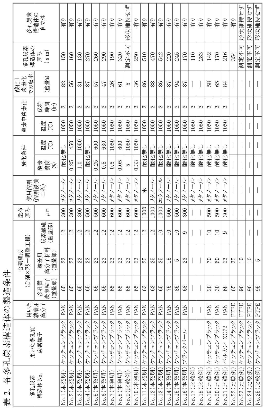
これらの試料(多孔炭素構造体No.1~No.10)について、収率及び厚さを測定し、自立性を観察した。結果を表2にまとめて示す。
また、多孔炭素構造体No.5の試料の細部を走査型電子顕微鏡(SEM、JEOL社製、JSM-7800F)を用いて観察した。これらの結果を図8と図9に示す。
図9は、図8のSEM像を拡大して示す図である。
図8には「直径200nm以上、10000nm以下の細孔」に相当する空孔12が示され、図9によれば、「直径1nm以上、1000nm以下の細孔」に相当する空孔11が示される。
(1)直径1nm以上、1000nm以下の細孔の占める細孔容積
3Flex(Micromeritics Instrument Corp.製)を用いて窒素吸着法により得られた吸着等温線からBJH法を用いて求めた。
(2)直径1nm以上、200nm以下の細孔の占める細孔容積
3Flex(Micromeritics Instrument Corp.製)を用いて窒素吸着法により得られた吸着等温線からBJH法を用いて求めた。
(3)直径1μm以上、200μm以下の細孔の占める細孔容積
AutoPoreIV(Micromeritics Instrument Corp.製)を用いた水銀圧入法により、細孔径10nm~200000nm(0.01μm~200μm)の範囲の細孔容積を測定し、細孔直径1μmから200μmの細孔容積の値を用いた。
(4)BET法比表面積
3Flex(Micromeritics Instrument Corp.製)を用いて窒素吸着法により得られた吸着等温線からBET法に従って求めた。
(5)t-プロット外部比表面積
3Flex(Micromeritics Instrument Corp.製)を用いて窒素吸着法により得られた吸着等温線をもとに、窒素の吸着層の厚みを横軸、吸着量を縦軸にプロットしたグラフよりt-プロット法で求めた。
(6)t-プロットミクロ孔比表面積
上記BET法の比表面積から上記t-プロット外部比表面積を引いた値で定義される。
(7)見かけ密度
多孔炭素構造体の重量をその体積で割って求めた。
(8)空孔率(%)
次記の計算により求めた。
(1-多孔炭素構造体の見かけ密度/多孔炭素構造体構成材料の真密度)×100
(9)直径200nm以上、10000nm以下の細孔の占める細孔容積
AutoPoreIV(Micromeritics Instrument Corp.製)を用いた水銀圧入法により、細孔径10nm~200000nm(0.01μm~200μm)の範囲の細孔容積を測定し、細孔直径200nmから10000nmの細孔容積の値を用いた。
(10)F含有量(%)
試料を秤量し、分析装置の燃焼管内でアルゴン・酸素混合ガス中で燃焼させ(AQF-2100H、GA-210(三菱化学製)使用)、発生したガスを過酸化水素水溶液に吸収後、吸収液の一部をDIONEX 製イオンクロマトグラフィーICS1600を用いて分析した。試料は秤量からn=2~3で測定し、測定値の平均値を求めて試料中のF含有量を計算した。
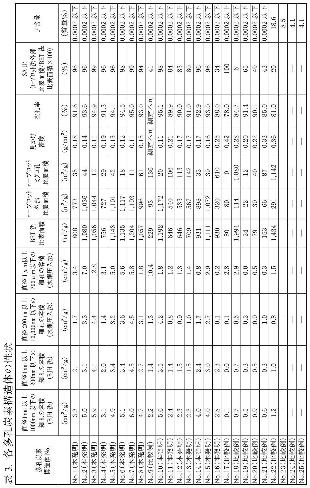
これに対して、多孔炭素構造体No.9の試料は、上述の条件(a)~(d)のすべてを満たすものではないことが分かった。
更に、多孔炭素構造体No.1~8及び10の試料は全て、その多孔炭素構造体に含まれるフッ素(F)含有量が0.0002質量%以下であることも確認した。
しかしながら、酸素5%で酸化した多孔炭素構造体No.9の試料は、高濃度酸素によりケッチェンブラック(登録商標)粒子の酸化焼失量が増加し、そのことで粒子結合部分にあるPANも焼失が大きくなり、多孔炭素構造体強度が低下したと理解される。つまり、多孔炭素構造体No.9の試料では、本発明の多孔炭素構造体No.1~8及び10の試料のような炭素化処理がなされず、多孔炭素構造体の自立性を得ることができなかったと理解される。
実施例2Aでは、実施例1Aで製造(作製)した本発明の多孔炭素構造体No.1~8及び10の各試料を正極構造体690(図6)に用いたCR2032型のコインセル601(図6)を作製し、電池特性を評価した。
酸素濃度5%で1050℃まで酸化処理した多孔炭素構造体No.9の試料は、強度が弱く脆いため正極として電池評価に供する状態ではないため、実施しなかった。
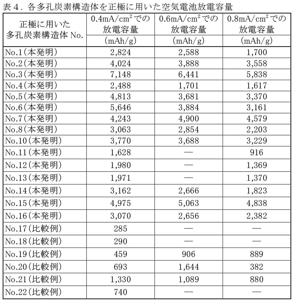
電池評価の条件は、電流密度0.4mA/cm2に加え、より高速の電流密度0.6mA/cm2と0.8mA/cm2でも行い、電圧が2.3Vまで下がった時点を放電終点として、得られた放電容量を正極として用いた多孔炭素構造体重量で割ることで、正極重量当りの放電容量を算出した。
測定には、充放電試験機(北斗電工株式会社製、HJ1001SD8)を用いた。結果を表4に示す。
実施例1Bでは、本発明の多孔炭素構造体試料(多孔炭素構造体No.11~16)と比較用試料(多孔炭素構造体No.17~25)の作製及び作製した多孔炭素構造体試料と比較用試料の性状について述べる。
最初に、多孔質炭素粒子65重量%、炭素繊維10重量%、結着用高分子材料25重量%及びそれらを均一に分散するN-メチルピロリドンからなる溶媒を用いて合剤スラリーを調製した(図4の工程S1)。
ここで、多孔質炭素粒子としてはケッチェンブラック(登録商標)を65重量%含むカーボンブラックを用いた。
炭素繊維としては繊維平均径7μm、平均長さ3mmの炭素繊維を用いた。結着用高分子材料としてはポリアクリロニトリル(PAN)を用いた。
合剤スラリーは、ドクターブレードを用いた湿式製膜法にて均一な厚みに成型してシート化した(図4の工程S2)。成形後、非溶媒誘起相分離法にて水(貧溶媒)中に浸漬して、成型試料を多孔質膜化した。
次に、試料から揮発性の溶媒を取り除く50~80℃で10時間以上の乾燥工程(図4の工程S4)を行い、引き続き大気中で280℃で3時間の不融化熱処理(図4の工程S5)を行い、その後、炭素化処理工程(図4の工程S6)として、真空置換後の窒素ガス雰囲気下の焼成炉中で1000℃で3時間の焼成を行って、長さ140mm、幅100mm、厚さ510μmの多孔炭素構造体試料を作製した(図4の工程S7)。
本発明の多孔炭素構造体No.11の試料の作製(製造)条件は表2に示すとおりである。
上記工程により作製した多孔炭素構造体No.11の試料の特性を、多孔炭素構造体No.1~No.10の各試料の性状と同じ方法で調べ、その結果を表3に示す。
具体的には、ケッチェンブラック組成は79重量%、厚みは、表2に示すとおり510μm、目付は10.8mg/cm2、BET法比表面積は、表3に示すとおり646m2/g、t-プロット外部比表面積は、表3に示すとおり540m2/gとなり、全体のt-プロット外部比表面積比(SA比)は、表3に示すとおり84%となった。また、空孔率は、表3に示すとおり89.9%であった。
得られた多孔炭素構造体の走査型2次電子顕微鏡像を図10に示す。空孔を有する海綿状であるにもかかわらず、自立する強度を有していた。
表3に示すとおり、多孔炭素構造体No.11の試料は、t-プロット外部比表面積が540m2/gであるから、300m2/g以上、1600m2/g以下の範囲(上述の条件(a))にあり、直径1nm以上、200nm以下の細孔の占める細孔容積が1.4cm3/gであるから、1.2cm3/g以上、7.0cm3/g以下の範囲(上述の条件(b))にあり、直径1nm以上、1000nm以下の細孔の占める細孔容積が2.4cm3/gであるから、2.3cm3/g以上、10.0cm3/g以下の範囲(上述の条件(c))にあり、そして、空孔率が全体で89.9%であるから、全体で80%以上、99%以下の範囲(上述の条件(d))にあり、上述の条件(a)~(d)のすべてを満たすことが確認された。
多孔炭素構造体No.12の試料は、非溶媒誘起相分離法の貧溶媒としてメタノールを用いた以外は、多孔炭素構造体No.11と同様にして多孔炭素構造体を作製した。具体的な作製(製造)条件は表2に示すとおりである。
上記工程により作製した多孔炭素構造体No.12の試料の特性を、多孔炭素構造体No.1~No.10の各試料の性状と同じ方法で調べ、その結果を表3に示す。
具体的には、ケッチェンブラック組成は79重量%、厚みは、表2に示すとおり470μm、目付は7.9mg/cm2、BET法比表面積は、表3に示すとおり646m2/g、t-プロット外部比表面積は、表3に示すとおり533m2/gとなり、全体のt-プロット外部比表面積比(SA比)は、表3に示すとおり83%となった。また、空孔率は、表3に示すとおり90%であった。
表3に示すとおり、多孔炭素構造体No.12の試料は、t-プロット外部比表面積が533m2/gであるから上述の条件(a)を満たし、直径1nm以上、200nm以下の細孔の占める細孔容積が1.5cm3/gであるから上述の条件(b)を満たし、直径1nm以上、1000nm以下の細孔の占める細孔容積が2.3cm3/gであるから上述の条件(c)を満たし、そして、空孔率が全体で90.0%であるから上述の条件(d)を満たし、そのため、上述の条件(a)~(d)のすべてを満たすことが確認された。
多孔炭素構造体No.12の試料は、非溶媒誘起相分離法の貧溶媒としてエタノールを用いた以外は、多孔炭素構造体No.11と同様にして多孔炭素構造体を作製した。具体的な作製(製造)条件は表2に示すとおりである。
上記工程により作製した多孔炭素構造体No.12の試料の特性を、多孔炭素構造体No.1~No.10の各試料の性状と同じ方法で調べ、その結果を表3に示す。
具体的には、ケッチェンブラック組成は79重量%、厚みは、表2に示すとおり542μm、目付は9.4mg/cm2、BET法比表面積は、表3に示すとおり709m2/g、t-プロット外部比表面積は、表3に示すとおり567m2/gとなり、全体のt-プロット外部比表面積比(SA比)は、表3に示すとおり80%となった。また、空孔率は、表3に示すとおり91%であった。
表3に示すとおり、多孔炭素構造体No.13の試料は、t-プロット外部比表面積が567m2/gであるから上述の条件(a)を満たし、直径1nm以上、200nm以下の細孔の占める細孔容積が1.5cm3/gであるから上述の条件(b)を満たし、直径1nm以上、1000nm以下の細孔の占める細孔容積が2.3cm3/gであるから上述の条件(c)を満たし、そして、空孔率が全体で91.0%であるから上述の条件(d)を満たし、そのため、上述の条件(a)~(d)のすべてを満たすことが確認された。
多孔炭素構造体No.14、15の各試料は、調製した合剤スラリーの組成(合剤組成)としてそれぞれ、ケッチェンブラックを70重量%、炭素繊維を10重量%、そしてPANを20重量%としたもの、ケッチェンブラックを85重量%、炭素繊維を10重量%、そしてPANを5重量%としたものを用いた以外は、多孔炭素構造体No.11と同様にして多孔炭素構造体を作製した。具体的な作製(製造)条件は表2に示すとおりである。
上記工程により作製した多孔炭素構造体No.14、15の各試料の特性を、多孔炭素構造体No.1~No.10の各試料の性状と同じ方法で調べ、その結果を表3に示す。
具体的には、多孔炭素構造体No.14では、厚みは、表2に示すとおり220μm、目付は3.7mg/cm2、BET法比表面積は、表3に示すとおり931m2/g、t-プロット外部比表面積は、表3に示すとおり898m2/gとなり、全体のt-プロット外部比表面積比(SA比)は、表3に示すとおり96%となった。また、空孔率は、表3に示すとおり93%であった。
多孔炭素構造体No.15では、厚みは、表2に示すとおり245μm、目付は、4.0mg/cm2、BET法比表面積は、表3に示すとおり1111m2/g、t-プロット外部比表面積は、表3に示すとおり1072m2/gとなり、全体のt-プロット外部比表面積比(SA比)は、表3に示すとおり96%となった。また、空孔率は、表3に示すとおり93%であった。
表3に示すとおり、多孔炭素構造体No.14の試料は、t-プロット外部比表面積が898m2/gであるから上述の条件(a)を満たし、直径1nm以上、200nm以下の細孔の占める細孔容積が2.4cm3/gであるから上述の条件(b)を満たし、直径1nm以上、1000nm以下の細孔の占める細孔容積が4.0cm3/gであるから上述の条件(c)を満たし、そして、空孔率が全体で92.9%であるから上述の条件(d)を満たし、そのため、上述の条件(a)~(d)のすべてを満たすことが確認された。
また、表3に示すとおり、多孔炭素構造体No.15の試料も、t-プロット外部比表面積が1072m2/gであるから上述の条件(a)を満たし、直径1nm以上、200nm以下の細孔の占める細孔容積が3.0cm3/gであるから上述の条件(b)を満たし、直径1nm以上、1000nm以下の細孔の占める細孔容積が4.0cm3/gであるから上述の条件(c)を満たし、そして、空孔率が全体で93.0%であるから上述の条件(d)を満たし、そのため、上述の条件(a)~(d)のすべてを満たすことが確認された。
多孔炭素構造体No.16の試料は、多孔質炭素粒子としてブラックパール(登録商標)2000(CABOT社製)を用い、調製した合剤スラリーの組成(合剤組成)として、ブラックパール(登録商標)を68重量%、炭素繊維を9重量%、PANを23重量%であるものを用いた以外は、多孔炭素構造体No.11と同様にして多孔炭素構造体を作製した。具体的な作製(製造)条件は表2に示すとおりである。
上記工程により作製した多孔炭素構造体No.16の試料の特性を、多孔炭素構造体No.1~No.10の各試料の性状と同じ方法で調べ、その結果を表3に示す。
具体的には、多孔炭素構造体No.16では、厚みは、表2に示すとおり170μm、目付は4.3mg/cm2、BET法比表面積は、表3に示すとおり930m2/g、t-プロット外部比表面積は、表3に示すとおり320m2/gとなり、全体のt-プロット外部比表面積比(SA比)は、表3に示すとおり34%となった。また、空孔率は、表3に示すとおり88%であった。
表3に示すとおり、多孔炭素構造体No.16の試料は、t-プロット外部比表面積が320m2/gであるから上述の条件(a)を満たし、直径1nm以上、200nm以下の細孔の占める細孔容積が2.3cm3/gであるから上述の条件(b)を満たし、直径1nm以上、1000nm以下の細孔の占める細孔容積が2.8cm3/gであるから上述の条件(c)を満たし、そして、空孔率が全体で88.0%であるから上述の条件(d)を満たし、そのため、上述の条件(a)~(d)のすべてを満たすことが確認された。
多孔炭素構造体No.17の試料は、合成スラリーからドクターブレードを用いた湿式製膜法にて均一な厚みに成型して得られるシートとして炭素繊維からなるガス拡散層シート(東レ株式会社製TGP-H-060)を用いた以外は、多孔炭素構造体No.11と同様にして多孔炭素構造体を作製した。具体的な作製(製造)条件は表2に示すとおりである。
上記工程により作製した多孔炭素構造体No.17の試料の特性を、多孔炭素構造体No.1~No.10の各試料の性状と同じ方法で調べ、その結果を表3に示す。
具体的には、厚みは、表2に示すとおり190μm、目付は8.1mg/cm2、BET法比表面積は、表3に示すとおり80m2/gと小さく、t-プロット外部比表面積は、表3に示すとおり80m2/gと小さかった。また、空孔率は、表3に示すとおり78%と低かった。
表3に示すとおり、多孔炭素構造体No.17の試料は、上述の条件(a)~(d)のいずれも満たしておらず、上述の条件(a)~(d)のすべてを満たすものではないことが確認された。
多孔炭素構造体No.18の試料は、合成スラリーからドクターブレードを用いた湿式製膜法にて均一な厚みに成型して得られるシートとして活性炭繊維織布(フタムラ化学株式会社製CL1420)を用いた以外は、多孔炭素構造体No.11と同様にして多孔炭素構造体を作製した。具体的な作製(製造)条件は表2に示すとおりである。
上記工程により作製した多孔炭素構造体No.18の試料の特性を、多孔炭素構造体No.1~No.10の各試料の性状と同じ方法で調べ、その結果を表3に示す。
厚みは、表2に示すとおり283μm、目付は7.9mg/cm2、BET法比表面積は、表3に示すとおり1994m2/gと大きく、t-プロット外部比表面積は、表3に示すとおり114m2/gと小さく、全体のt-プロット外部比表面積比(SA比)は、表3に示すとおり5.7%と低かった。
表3に示すとおり、多孔炭素構造体No.18の試料は、上述の条件(a)~(d)のすべてを満たすものではないことが確認された。
多孔炭素構造体No.19、20の各試料は、調製した合剤スラリーの組成(合剤組成)としてそれぞれ、ケッチェンブラックを20重量%、炭素繊維を10重量%、そしてPANを70重量%としたもの、ケッチェンブラックを30重量%、炭素繊維を10重量%、そしてPANを60重量%としたものを用いた以外は、多孔炭素構造体No.11と同様にして多孔炭素構造体を作製した。具体的な作製(製造)条件は表2に示すとおりである。
上記工程により作製した多孔炭素構造体No.19、20の各試料の特性を、多孔炭素構造体No.1~No.10の各試料の性状と同じ方法で調べ、その結果を表3に示す。
具体的には、多孔炭素構造体No.19では、厚みは、表2に示すとおり142μm、目付は2.8mg/cm2、BET法比表面積は、表3に示すとおり34m2/g、t-プロット外部比表面積は、表3に示すとおり22m2/gとなり、全体のt-プロット外部比表面積比(SA比)は、表3に示すとおり65%となった。また、空孔率は、表3に示すとおり91.4%であった。このように、BET法比表面積やt-プロット外部比表面積が小さかった。
多孔炭素構造体No.15では、厚みは、表2に示すとおり170μm、目付は3.8mg/cm2、BET法比表面積は、表3に示すとおり79m2/g、t-プロット外部比表面積は、表3に示すとおり39m2/gとなり、全体のt-プロット外部比表面積比(SA比)は、表3に示すとおり49%となった。また、空孔率は、表3に示すとおり90.1%であった。
このように、多孔炭素構造体No.19、20では、BET法比表面積やt-プロット外部比表面積が小さかった。
表3に示すとおり、多孔炭素構造体No.19、20のいずれの試料も、上述の条件(a)~(d)のすべてを満たすものではないことが確認された。
多孔炭素構造体No.21の試料は、多孔質炭素粒子としてバルカン(登録商標)XC-72(CABOT社製)を用い、調製した合剤スラリーの組成(合剤組成)として、バルカン(登録商標)XC-72を68重量%、炭素繊維を9重量%、PANを23重量%であるものを用いた以外は、多孔炭素構造体No.11と同様にして多孔炭素構造体を作製した。具体的な作製(製造)条件は表2に示すとおりである。
上記工程により作製した多孔炭素構造体No.21の試料の特性を、多孔炭素構造体No.1~No.10の各試料の性状と同じ方法で調べ、その結果を表3に示す。
具体的には、多孔炭素構造体No.21では、厚みは、表2に示すとおり216μm、目付は7.1mg/cm2、BET法比表面積は、表3に示すとおり153m2/g、t-プロット外部比表面積は、表3に示すとおり66m2/gとなり、全体のt-プロット外部比表面積比(SA比)は、表3に示すとおり43%となった。また、空孔率は、表3に示すとおり85%であった。
表3に示すとおり、多孔炭素構造体No.21の試料は、上述の条件(a)~(d)のすべてを満たすものではないことが確認された。
多孔炭素構造体No.22の試料では、調製した合剤スラリーの組成(合剤組成)として、ケッチェンブラック(登録商標)を65重量%、バインダーとしてPTFE(ダイキン工業株式会社製)を35重量%としたものを用い、これを水溶媒に分散して合剤スラリー溶液とした。なお、PTFEとは、ポリテトラフルオロエチレンのことである。
次に、支持材として活性炭繊維織布(CL1420、フタムラ化学(株)製)を用いてこの基膜上に上述の水分散の合剤スラリーをドクターブレードの湿式製膜法で均一な厚みに成型して活性炭繊維支持材に一体化したシートを作製した。
次に、作製したシートから揮発性の溶媒を取り除き、乾燥して活性炭繊維織布の一体化した多孔炭素膜を作製した。これを多孔炭素構造体として用いた。
具体的な作製(製造)条件は表2に示すとおりである。
上記工程により作製した多孔炭素構造体No.22の試料の特性を、多孔炭素構造体No.1~No.10の各試料の性状と同じ方法で調べ、その結果を表3に示す。
具体的には、多孔炭素構造体No.22では、厚みは、表2に示すとおり354μm、目付は12.6mg/cm2、BET法比表面積は、表3に示すとおり1434m2/g、t-プロット外部比表面積は、表3に示すとおり291m2/gとなり、全体のt-プロット外部比表面積比(SA比)は、表3に示すとおり20%となった。また、空孔率は、表3に示すとおり81%であった。
多孔炭素構造体No.22では、厚みは、表2に示すとおり354μm、目付は、12.6mg/cm2、BET法比表面積は、表3に示すとおり1434m2/g、t-プロット外部比表面積は、表3に示すとおり1142m2/gとなり、全体のt-プロット外部比表面積比(SA比)は、表3に示すとおり20%となった。また、空孔率は、表3に示すとおり81%であった。
表3に示すとおり、多孔炭素構造体No.22の試料は、上述の条件(a)~(d)のすべてを満たすものではないことが確認された。
多孔炭素構造体No.23の試料では、調製した合剤スラリーの組成(合剤組成)として、ケッチェンブラック(登録商標)を90重量%、バインダーとしてPTFE(ダイキン工業株式会社製)を10重量%としたものを用い、これをエタノールに分散して合剤スラリーを調製した。
この合剤スラリーをドクターブレードの湿式製膜法にて均一な厚みに成型してシートを作製した。
次に、作製したシートから揮発性の溶媒を取り除き乾燥した結果、膜状物はひび割れ、自立膜にはならなかった。
具体的な作製(製造)条件は表2に示すとおりである。
多孔炭素構造体No.23の試料では、上述のとおり、自立膜は得られなかったため、表3に示すとおり、その試料の特性を調べることはできなかった。
多孔炭素構造体No.24の試料では、合成スラリーからシートを作製する際に10MPaでプレスして成形シートを作製した以外は、多孔炭素構造体No.23と同様にして行った。乾燥した膜状物はひび割れ、自立膜にはならなかった。
具体的な作製(製造)条件は表2に示すとおりである。
多孔炭素構造体No.24の試料では、上述のとおり、自立膜は得られなかったため、表3に示すとおり、その試料の特性を調べることはできなかった。
多孔炭素構造体No.24の試料では、調製した合剤スラリーの組成(合剤組成)として、ケッチェンブラック(登録商標)を95重量%、バインダーとしてPTFE(ダイキン工業株式会社製)を5重量%としたものを用いたこと以外は、多孔炭素構造体No.23と同様にして行った。乾燥した膜状物はひび割れ、自立膜にはならなかった。
具体的な作製(製造)条件は表2に示すとおりである。
多孔炭素構造体No.25の試料では、上述のとおり、自立膜は得られなかったため、表3に示すとおり、その試料の特性を調べることはできなかった。
実施例2Bでは、実施例1Bで製造(作製)した本発明の多孔炭素構造体No.11~16の各試料を正極構造体690(図6)に用いたCR2032型のコインセル601(図6)を作製し、電池特性を評価した。また、比較のために、比較用試料の多孔炭素構造体No.17~22の各試料を正極構造体690(図6)に用いたCR2032型のコインセル601を同様に作製し、電池特性を評価した。
なお、本発明の多孔炭素構造体No.13の試料を正極構造体690として用いるにあたり、多孔炭素構造体の表面に空気流通用の溝を形成した。具体的には、上述のとおり、非溶媒誘起相分離法の貧溶媒としてエタノールを用いて多孔炭素構造体を作製し、その後、湿潤状態の多孔炭素構造体の表面に碁盤目状の溝を形成処理し、空気電池として必要な空気の流路を多孔炭素構造体の表面に形成した。この流路の溝の幅は約2mm、溝の深さは約0.05mmであった。
多孔炭素構造体No.23~25の比較用試料については、上述のとおり、自立膜にはならず、正極として電池評価に供する状態ではなかったため、実施していない。
また、実施例2Bで製造(作製)したリチウム空気電池の幾つかについては、実施例2Aで製造(作製)したコインセル(リチウム空気電池)と同様、放電電流密度0.4mA/cm2に加え、より高速の放電電流密度0.6mA/cm2と0.8mA/cm2でも試験を行った。
その結果、本発明の多孔炭素構造体No.1~16の試料を正極構造体として用いる空気電池によれば、空気が十分に正極構造体690に供給されていて、十分な出力容量をもつ軽量の空気電池となることが確認された。
また、活性炭繊維織布などを支持体とする自立性を有さない多孔炭素構造体No.22の比較用試料を正極構造体として用いた場合、表4の放電電流密度0.4mA/cm2での放電容量が、本発明の自立可能な多孔炭素構造体No.1~16の試料を用いた場合に比べて、はるかに小さい。この結果は、本発明の自立可能な多孔炭素構造体の有用性を示しているといえる。
11 本発明の多孔炭素構造体の直径1nm以上、1000nm以下の細孔のイメージ
12 本発明の多孔炭素構造体の直径200nm以上、10000nm以下の細孔のイメージ
13 本発明の多孔炭素構造体の炭素繊維のイメージ
100、610 負極構造体
500 空気電池
510、620、621 正極構造体
520 負極用集電体電極
525 正極用集電体電極
540、660 セパレータ
600、601 コインセル
630 コインセル型拘束具
635 集電体
640 金属層
650 スペーサ
670 空間(電解質充填用空間)
680 金属メッシュ
690 多孔炭素構造体
Claims (25)
- 炭素を含んでなる骨格と空孔とを有する空気電池の正極用多孔炭素構造体であって、次記(a)~(d)のすべての条件を満たす、多孔炭素構造体。
(a)t-プロット外部比表面積が、300m2/g以上、1600m2/g以下の範囲、
(b)直径1nm以上、200nm以下の細孔の占める細孔容積が、1.2cm3/g以上、7.0cm3/g以下の範囲、
(c)直径1nm以上、1000nm以下の細孔の占める細孔容積が2.3cm3/g以上、10.0cm3/g以下の範囲、及び
(d)空孔率が、全体で80%以上、99%以下の範囲。 - 次記(e)の条件を更に満たす、請求項1記載の多孔炭素構造体。
(e)直径200nm以上、10000nm以下の細孔容積が2.3cm3/g以上、8.0cm3/g以下の範囲。 - 前記(b)の直径1nm以上、200nm以下の細孔の占める細孔容積が、2.2cm3/g以上、7.0cm3/g以下の範囲である、請求項1または2に記載の多孔炭素構造体。
- 前記(b)の直径1nm以上、200nm以下の細孔の占める細孔容積が、2.4cm3/gより大きく、6.0cm3/g以下の範囲である、請求項1~3のいずれかに記載の多孔炭素構造体。
- 前記(c)の直径1nm以上、1000nm以下の細孔の占める細孔容積が、4.0cm3/g以上、10.0cm3/g以下の範囲である、請求項1~4のいずれかに記載の多孔炭素構造体。
- 前記(c)の直径1nm以上、1000nm以下の細孔の占める細孔容積が、4.1cm3/g以上、9.0cm3/g以下の範囲である、請求項5に記載の多孔炭素構造体。
- 前記多孔炭素構造体の見かけ密度は、0.05g/cm3以上、0.20g/cm3以下の範囲である、請求項1~6のいずれかに記載の多孔炭素構造体。
- 前記(d)の空孔率が、全体で90%以上、99%以下の範囲である、請求項1~7のいずれかに記載の多孔炭素構造体。
- 前記骨格は炭素からなる、請求項1~8のいずれかに記載の多孔炭素構造体。
- 前記(a)のt-プロット外部比表面積が、900m2/g以上、1600m2/g以下の範囲である、請求項1~9のいずれかに記載の多孔炭素構造体。
- 前記多孔炭素構造体中のフッ素含有量が、0.0002質量%以下である、請求項1~10のいずれかに記載の多孔炭素構造体。
- 前記多孔炭素構造体が、自立性を有する請求項1~11のいずれかに記載の多孔炭素構造体。
- 多孔質炭素粒子および結着用高分子材料を含有する合剤スラリーを調製することと、
前記合剤スラリーを成型することと、
前記成型することによって得られた試料を、前記結着用高分子材料に対して溶解度が低い溶媒に浸漬させることと、
前記浸漬させることによって得られた試料を乾燥させることと、
前記乾燥させることによって得られた試料を炭素化処理することと、
を包含する、請求項1~12のいずれかに記載の多孔炭素構造体の製造方法。 - 前記炭素化処理が、酸化性ガス又は不活性ガスの雰囲気中で行われる、請求項13に記載の多孔炭素構造体の製造方法。
- 前記炭素化処理が酸化性ガスの雰囲気中で行われる場合、前記酸化性ガス中の酸素濃度は、0.03%より多く、5%未満の範囲である、請求項14に記載の多孔炭素構造体の製造方法。
- 前記炭素化処理の処理温度は、350℃以上、3000℃以下の範囲である、請求項13~15のいずれかに記載の多孔炭素構造体の製造方法。
- 前記炭素化処理は、前記炭素化処理により得られる生成物の直径1nm以上、1000nm以下の細孔の占める細孔容積が、前記多孔質炭素の細孔容積の細孔容積の1.02倍以上となるまで行う、請求項13~16のいずれかに記載の多孔炭素構造体の製造方法。
- 前記合剤スラリーは、さらに炭素繊維を含有する、請求項13~17のいずれかに記載の多孔炭素構造体の製造方法。
- 前記乾燥させることに続いて、かつ、前記炭素化処理することに先立って、前記乾燥させることによって得られた試料を不融化処理することをさらに包含する、請求項13~18のいずれかに記載の多孔炭素構造体の製造方法。
- 前記炭素化処理が酸化性ガスの雰囲気中で行われる場合、前記炭素化処理することに続いて、前記炭素化処理することによって得られた試料を不活性ガス雰囲気下でさらなる炭素化処理することをさらに包含する、請求項14~19のいずれかに記載の多孔炭素構造体の製造方法。
- 請求項1~12のいずれかに記載の多孔炭素構造体を含有する空気電池の正極材。
- 正極構造体、負極構造体、セパレータ、電解質部材を含む空気電池であって、
前記正極構造体は請求項1~12のいずれかに記載の多孔炭素構造体を有する、電池。 - 前記多孔炭素構造体に空気又は酸素が通る流路が形成されている、請求項22に記載の空気電池。
- 前記正極構造体は、空気又は酸素が通る流路が形成されている金属含有の正極基材を有し、前記正極基材は前記多孔炭素構造体と電気的に接触している、請求項22または23に記載の空気電池。
- 炭素を含んでなる骨格と空孔とを有し、自立性を有する空気電池の正極用多孔炭素構造体であって、次記(a)~(e)の少なくとも一つの条件を満たす、多孔炭素構造体。
(a)t-プロット外部比表面積が、300m2/g以上、1600m2/g以下の範囲、
(b)直径1nm以上、200nm以下の細孔の占める細孔容積が、1.2cm3/g以上、7.0cm3/g以下の範囲、
(c)直径1nm以上、1000nm以下の細孔の占める細孔容積が2.3cm3/g
以上、10.0cm3/g以下の範囲、
(d)空孔率が、全体で80%以上、99%以下の範囲、及び
(e)直径200nm以上、10000nm以下の細孔容積が2.3cm3/g以上、8.0cm3/g以下の範囲。
Priority Applications (4)
| Application Number | Priority Date | Filing Date | Title |
|---|---|---|---|
| CN202080035651.8A CN113841284B (zh) | 2019-05-23 | 2020-05-21 | 多孔碳结构体、其制备方法、使用该多孔碳结构体的正极材料以及使用该多孔碳结构体的电池 |
| JP2021520848A JP7177547B2 (ja) | 2019-05-23 | 2020-05-21 | 多孔炭素構造体、その製造方法、それを用いた正極材及びそれを用いた電池 |
| EP20809459.9A EP3975322B1 (en) | 2019-05-23 | 2020-05-21 | Porous carbon structure, manufacturing method therefor, positive electrode material using same, and battery using same |
| US17/611,984 US12272826B2 (en) | 2019-05-23 | 2020-05-21 | Porous carbon structure, manufacturing method therefor, positive electrode material using same, and battery using same |
Applications Claiming Priority (4)
| Application Number | Priority Date | Filing Date | Title |
|---|---|---|---|
| JP2019-096585 | 2019-05-23 | ||
| JP2019096585 | 2019-05-23 | ||
| JP2020034769 | 2020-03-02 | ||
| JP2020-034769 | 2020-03-02 |
Publications (1)
| Publication Number | Publication Date |
|---|---|
| WO2020235638A1 true WO2020235638A1 (ja) | 2020-11-26 |
Family
ID=73459092
Family Applications (1)
| Application Number | Title | Priority Date | Filing Date |
|---|---|---|---|
| PCT/JP2020/020143 Ceased WO2020235638A1 (ja) | 2019-05-23 | 2020-05-21 | 多孔炭素構造体、その製造方法、それを用いた正極材及びそれを用いた電池 |
Country Status (5)
| Country | Link |
|---|---|
| US (1) | US12272826B2 (ja) |
| EP (1) | EP3975322B1 (ja) |
| JP (1) | JP7177547B2 (ja) |
| CN (1) | CN113841284B (ja) |
| WO (1) | WO2020235638A1 (ja) |
Cited By (5)
| Publication number | Priority date | Publication date | Assignee | Title |
|---|---|---|---|---|
| JP2022090752A (ja) * | 2020-12-08 | 2022-06-20 | 国立研究開発法人物質・材料研究機構 | 空気電池用正極シート、および、それを用いた空気電池 |
| JP2023079084A (ja) * | 2021-11-26 | 2023-06-07 | 国立研究開発法人物質・材料研究機構 | 空気電池正極用の多孔炭素膜の製造方法、及びその方法で得られる多孔炭素膜を正極に用いた空気電池の製造方法 |
| JP2023079085A (ja) * | 2021-11-26 | 2023-06-07 | 国立研究開発法人物質・材料研究機構 | 多孔炭素膜製造用組成物、多孔炭素膜製造用シート、空気電池正極用の多孔炭素膜の製造方法、及びその方法で得られる多孔炭素膜を正極に用いた空気電池の製造方法 |
| WO2024142776A1 (ja) * | 2022-12-26 | 2024-07-04 | 国立研究開発法人物質・材料研究機構 | 炭素構造体、空気電池、及び炭素構造体の製造方法 |
| JP2024526572A (ja) * | 2021-07-01 | 2024-07-19 | ニッポン・コルンマイヤー・カーボン・グループ・ゲゼルシャフト・ミト・ベシュレンクテル・ハフツング | 炭化または黒鉛化された成形部品の製造方法 |
Families Citing this family (1)
| Publication number | Priority date | Publication date | Assignee | Title |
|---|---|---|---|---|
| CN121794222A (zh) * | 2023-12-28 | 2026-04-03 | 株式会社3Dc | 碳材料、导电助剂、分散液、电极用组合物、电极用浆料、电极、锂离子电池及碳材料的制造方法 |
Citations (6)
| Publication number | Priority date | Publication date | Assignee | Title |
|---|---|---|---|---|
| JPS5852548B2 (ja) | 1975-05-07 | 1983-11-24 | イムペリアル・メタル・インダストリイス・(キノツチ)・リミテツド | チタン合金およびその製法 |
| JP2012252995A (ja) * | 2011-05-10 | 2012-12-20 | Hitachi Ltd | 金属空気二次電池 |
| JP2015026482A (ja) * | 2013-07-25 | 2015-02-05 | 国立大学法人北海道大学 | 多孔質炭素材料及びその製造方法 |
| WO2016104625A1 (ja) * | 2014-12-26 | 2016-06-30 | 新日鐵住金株式会社 | 金属空気電池用電極 |
| JP2016532274A (ja) * | 2013-09-06 | 2016-10-13 | エスジーエル・カーボン・エスイー | 炭素繊維製電極基体 |
| JP2018133168A (ja) | 2017-02-14 | 2018-08-23 | パナソニックIpマネジメント株式会社 | リチウム空気電池及びその使用方法 |
Family Cites Families (16)
| Publication number | Priority date | Publication date | Assignee | Title |
|---|---|---|---|---|
| WO2004112174A1 (ja) * | 2003-06-11 | 2004-12-23 | Matsushita Electric Industrial Co., Ltd. | 酸素還元用電極の製造方法ならびに酸素還元用電極及びそれを用いた電気化学素子 |
| US8142883B2 (en) * | 2005-09-29 | 2012-03-27 | Takashi Chida | Porous carbon sheet and process for production thereof |
| CN102044673B (zh) * | 2006-04-07 | 2012-11-21 | 三菱化学株式会社 | 锂二次电池正极材料用锂镍锰钴系复合氧化物粉体 |
| JP5481646B2 (ja) * | 2008-06-04 | 2014-04-23 | 清蔵 宮田 | 炭素触媒、燃料電池、蓄電装置 |
| US8481187B2 (en) * | 2009-09-10 | 2013-07-09 | Battelle Memorial Institute | High-energy metal air batteries |
| KR101232263B1 (ko) * | 2011-03-16 | 2013-02-12 | 한국과학기술연구원 | 리튬-공기 전지용 탄소계 양극 및 이의 제조 방법 |
| JP5852548B2 (ja) | 2012-06-12 | 2016-02-03 | トヨタ自動車株式会社 | 多孔質炭素及び金属空気電池 |
| CN105379000B (zh) * | 2013-07-17 | 2019-08-27 | 印制能源技术有限公司 | 能量储存装置 |
| JP2015076125A (ja) * | 2013-10-04 | 2015-04-20 | トヨタ自動車株式会社 | 多孔質炭素及び金属空気電池 |
| KR101556470B1 (ko) * | 2014-03-31 | 2015-10-02 | 연세대학교 산학협력단 | 중질유분의 분해반응을 이용한 탄소 구조체의 제조방법 |
| JP6436085B2 (ja) | 2014-07-15 | 2018-12-12 | 東レ株式会社 | 金属空気電池用電極材料 |
| KR101804005B1 (ko) * | 2014-10-17 | 2017-12-04 | 주식회사 엘지화학 | 리튬 공기 전지용 양극, 이의 제조방법 및 이를 포함하는 리튬 공기 전지 |
| JP6320333B2 (ja) * | 2015-03-20 | 2018-05-09 | 富士フイルム株式会社 | 複合体、複合体の製造方法及び燃料電池触媒 |
| WO2017104772A1 (ja) * | 2015-12-17 | 2017-06-22 | 日本ゼオン株式会社 | 繊維状炭素ナノ構造体分散液 |
| JP6814339B2 (ja) * | 2016-01-15 | 2021-01-20 | 日鉄ケミカル&マテリアル株式会社 | 触媒担体用炭素材料、固体高分子形燃料電池用触媒層、及び固体高分子形燃料電池 |
| TWI601689B (zh) * | 2016-02-01 | 2017-10-11 | 台灣奈米碳素股份有限公司 | 含氮之多孔性碳材料及其電容與製造方法 |
-
2020
- 2020-05-21 EP EP20809459.9A patent/EP3975322B1/en active Active
- 2020-05-21 WO PCT/JP2020/020143 patent/WO2020235638A1/ja not_active Ceased
- 2020-05-21 JP JP2021520848A patent/JP7177547B2/ja active Active
- 2020-05-21 CN CN202080035651.8A patent/CN113841284B/zh active Active
- 2020-05-21 US US17/611,984 patent/US12272826B2/en active Active
Patent Citations (6)
| Publication number | Priority date | Publication date | Assignee | Title |
|---|---|---|---|---|
| JPS5852548B2 (ja) | 1975-05-07 | 1983-11-24 | イムペリアル・メタル・インダストリイス・(キノツチ)・リミテツド | チタン合金およびその製法 |
| JP2012252995A (ja) * | 2011-05-10 | 2012-12-20 | Hitachi Ltd | 金属空気二次電池 |
| JP2015026482A (ja) * | 2013-07-25 | 2015-02-05 | 国立大学法人北海道大学 | 多孔質炭素材料及びその製造方法 |
| JP2016532274A (ja) * | 2013-09-06 | 2016-10-13 | エスジーエル・カーボン・エスイー | 炭素繊維製電極基体 |
| WO2016104625A1 (ja) * | 2014-12-26 | 2016-06-30 | 新日鐵住金株式会社 | 金属空気電池用電極 |
| JP2018133168A (ja) | 2017-02-14 | 2018-08-23 | パナソニックIpマネジメント株式会社 | リチウム空気電池及びその使用方法 |
Non-Patent Citations (3)
| Title |
|---|
| JOURNAL OF PRINTING SCIENCE AND TECHNOLOGY, vol. 44, no. 3, 2007, pages 9 - 19 |
| See also references of EP3975322A4 |
| TANSO, vol. 222, 2006, pages 140 - 146 |
Cited By (10)
| Publication number | Priority date | Publication date | Assignee | Title |
|---|---|---|---|---|
| JP2022090752A (ja) * | 2020-12-08 | 2022-06-20 | 国立研究開発法人物質・材料研究機構 | 空気電池用正極シート、および、それを用いた空気電池 |
| JP7648126B2 (ja) | 2020-12-08 | 2025-03-18 | 国立研究開発法人物質・材料研究機構 | 空気電池用正極シート、および、それを用いた空気電池 |
| JP2024526572A (ja) * | 2021-07-01 | 2024-07-19 | ニッポン・コルンマイヤー・カーボン・グループ・ゲゼルシャフト・ミト・ベシュレンクテル・ハフツング | 炭化または黒鉛化された成形部品の製造方法 |
| JP7776540B2 (ja) | 2021-07-01 | 2025-11-26 | ニッポン・コルンマイヤー・カーボン・グループ・ゲゼルシャフト・ミト・ベシュレンクテル・ハフツング | 炭化または黒鉛化された成形部品の製造方法 |
| JP2023079084A (ja) * | 2021-11-26 | 2023-06-07 | 国立研究開発法人物質・材料研究機構 | 空気電池正極用の多孔炭素膜の製造方法、及びその方法で得られる多孔炭素膜を正極に用いた空気電池の製造方法 |
| JP2023079085A (ja) * | 2021-11-26 | 2023-06-07 | 国立研究開発法人物質・材料研究機構 | 多孔炭素膜製造用組成物、多孔炭素膜製造用シート、空気電池正極用の多孔炭素膜の製造方法、及びその方法で得られる多孔炭素膜を正極に用いた空気電池の製造方法 |
| JP7486129B2 (ja) | 2021-11-26 | 2024-05-17 | 国立研究開発法人物質・材料研究機構 | 空気電池正極用の多孔炭素膜の製造方法、及びその方法で得られる多孔炭素膜を正極に用いた空気電池の製造方法 |
| JP7525116B2 (ja) | 2021-11-26 | 2024-07-30 | 国立研究開発法人物質・材料研究機構 | 多孔炭素膜製造用組成物、及び多孔炭素膜製造用シート |
| WO2024142776A1 (ja) * | 2022-12-26 | 2024-07-04 | 国立研究開発法人物質・材料研究機構 | 炭素構造体、空気電池、及び炭素構造体の製造方法 |
| JP2024092093A (ja) * | 2022-12-26 | 2024-07-08 | 国立研究開発法人物質・材料研究機構 | 炭素構造体、空気電池、及び炭素構造体の製造方法 |
Also Published As
| Publication number | Publication date |
|---|---|
| CN113841284B (zh) | 2025-02-07 |
| EP3975322A1 (en) | 2022-03-30 |
| US12272826B2 (en) | 2025-04-08 |
| JP7177547B2 (ja) | 2022-11-24 |
| EP3975322B1 (en) | 2024-11-13 |
| CN113841284A (zh) | 2021-12-24 |
| EP3975322A4 (en) | 2024-03-20 |
| JPWO2020235638A1 (ja) | 2020-11-26 |
| US20220255085A1 (en) | 2022-08-11 |
Similar Documents
| Publication | Publication Date | Title |
|---|---|---|
| US12272826B2 (en) | Porous carbon structure, manufacturing method therefor, positive electrode material using same, and battery using same | |
| CN108475586B (zh) | 非水系锂蓄电元件 | |
| US20230378471A1 (en) | Binder that is composite of single-walled carbon nanotube and ptfe, and composition for producing electrode and secondary battery using same | |
| US11942621B2 (en) | Positive electrode coating liquid, positive electrode precursor, and nonaqueous lithium electric storage element | |
| JP2018061037A (ja) | 非水系リチウム型蓄電素子 | |
| JP2014185074A (ja) | カーボンナノホーン集合体、これを用いた電極材料及びその製造方法 | |
| Mijailović et al. | Core–shell carbon fiber@ Co1. 5Mn1. 5O4 mesoporous spinel electrode for high performance symmetrical supercapacitors | |
| JP2020013875A (ja) | 非水系リチウム蓄電素子 | |
| KR101893268B1 (ko) | 기공 네트를 포함하는 탄소나노섬유 및 그의 제조방법 | |
| JP7541767B2 (ja) | 空気電池用正極シート、それを製造する方法、および、それを用いた空気電池 | |
| CN119585201A (zh) | 多孔碳材料及其制造方法、以及使用该多孔碳材料的蓄电器件 | |
| JP7486129B2 (ja) | 空気電池正極用の多孔炭素膜の製造方法、及びその方法で得られる多孔炭素膜を正極に用いた空気電池の製造方法 | |
| JP7497037B2 (ja) | 空気電池の正極用多孔炭素膜電極、及びそれを用いた空気電池 | |
| JP7598590B2 (ja) | 電解液を含む正極及びそれを用いる空気電池、並びに正極への電解液注液方法及びそれを用いる空気電池の製法 | |
| JP7648126B2 (ja) | 空気電池用正極シート、および、それを用いた空気電池 | |
| JP7525116B2 (ja) | 多孔炭素膜製造用組成物、及び多孔炭素膜製造用シート | |
| JP2018061019A (ja) | 非水系リチウム蓄電素子 | |
| JP7219118B2 (ja) | 非水系リチウム型蓄電素子用正極 | |
| KR102589238B1 (ko) | 리튬이온전지용 음극재 및 이의 제조방법 | |
| JP2024092093A (ja) | 炭素構造体、空気電池、及び炭素構造体の製造方法 | |
| KR102572838B1 (ko) | 금속공기전지용 양극재 및 이의 제조방법 | |
| KR102572836B1 (ko) | 금속공기전지용 양극재 및 이의 제조방법 | |
| JP2018056402A (ja) | 正極前駆体 | |
| WO2025109869A1 (ja) | 空気電池の正極に用いる多孔炭素膜形成用の多孔質炭素粒子、空気電池の正極用の多孔炭素膜、及び空気電池 | |
| JP2018056443A (ja) | 正極前駆体 |
Legal Events
| Date | Code | Title | Description |
|---|---|---|---|
| 121 | Ep: the epo has been informed by wipo that ep was designated in this application |
Ref document number: 20809459 Country of ref document: EP Kind code of ref document: A1 |
|
| ENP | Entry into the national phase |
Ref document number: 2021520848 Country of ref document: JP Kind code of ref document: A |
|
| NENP | Non-entry into the national phase |
Ref country code: DE |
|
| ENP | Entry into the national phase |
Ref document number: 2020809459 Country of ref document: EP Effective date: 20211223 |
|
| WWG | Wipo information: grant in national office |
Ref document number: 202080035651.8 Country of ref document: CN |
|
| WWG | Wipo information: grant in national office |
Ref document number: 17611984 Country of ref document: US |