WO2020235682A1 - Dispositif d'affichage - Google Patents
Dispositif d'affichage Download PDFInfo
- Publication number
- WO2020235682A1 WO2020235682A1 PCT/JP2020/020368 JP2020020368W WO2020235682A1 WO 2020235682 A1 WO2020235682 A1 WO 2020235682A1 JP 2020020368 W JP2020020368 W JP 2020020368W WO 2020235682 A1 WO2020235682 A1 WO 2020235682A1
- Authority
- WO
- WIPO (PCT)
- Prior art keywords
- display
- display plate
- display device
- behind
- plate
- Prior art date
- Legal status (The legal status is an assumption and is not a legal conclusion. Google has not performed a legal analysis and makes no representation as to the accuracy of the status listed.)
- Ceased
Links
Images


Classifications
-
- B—PERFORMING OPERATIONS; TRANSPORTING
- B60—VEHICLES IN GENERAL
- B60K—ARRANGEMENT OR MOUNTING OF PROPULSION UNITS OR OF TRANSMISSIONS IN VEHICLES; ARRANGEMENT OR MOUNTING OF PLURAL DIVERSE PRIME-MOVERS IN VEHICLES; AUXILIARY DRIVES FOR VEHICLES; INSTRUMENTATION OR DASHBOARDS FOR VEHICLES; ARRANGEMENTS IN CONNECTION WITH COOLING, AIR INTAKE, GAS EXHAUST OR FUEL SUPPLY OF PROPULSION UNITS IN VEHICLES
- B60K35/00—Instruments specially adapted for vehicles; Arrangement of instruments in or on vehicles
- B60K35/20—Output arrangements, i.e. from vehicle to user, associated with vehicle functions or specially adapted therefor
- B60K35/21—Output arrangements, i.e. from vehicle to user, associated with vehicle functions or specially adapted therefor using visual output, e.g. blinking lights or matrix displays
- B60K35/22—Display screens
-
- B—PERFORMING OPERATIONS; TRANSPORTING
- B60—VEHICLES IN GENERAL
- B60K—ARRANGEMENT OR MOUNTING OF PROPULSION UNITS OR OF TRANSMISSIONS IN VEHICLES; ARRANGEMENT OR MOUNTING OF PLURAL DIVERSE PRIME-MOVERS IN VEHICLES; AUXILIARY DRIVES FOR VEHICLES; INSTRUMENTATION OR DASHBOARDS FOR VEHICLES; ARRANGEMENTS IN CONNECTION WITH COOLING, AIR INTAKE, GAS EXHAUST OR FUEL SUPPLY OF PROPULSION UNITS IN VEHICLES
- B60K35/00—Instruments specially adapted for vehicles; Arrangement of instruments in or on vehicles
- B60K35/20—Output arrangements, i.e. from vehicle to user, associated with vehicle functions or specially adapted therefor
- B60K35/28—Output arrangements, i.e. from vehicle to user, associated with vehicle functions or specially adapted therefor characterised by the type of the output information, e.g. video entertainment or vehicle dynamics information; characterised by the purpose of the output information, e.g. for attracting the attention of the driver
-
- B—PERFORMING OPERATIONS; TRANSPORTING
- B60—VEHICLES IN GENERAL
- B60K—ARRANGEMENT OR MOUNTING OF PROPULSION UNITS OR OF TRANSMISSIONS IN VEHICLES; ARRANGEMENT OR MOUNTING OF PLURAL DIVERSE PRIME-MOVERS IN VEHICLES; AUXILIARY DRIVES FOR VEHICLES; INSTRUMENTATION OR DASHBOARDS FOR VEHICLES; ARRANGEMENTS IN CONNECTION WITH COOLING, AIR INTAKE, GAS EXHAUST OR FUEL SUPPLY OF PROPULSION UNITS IN VEHICLES
- B60K35/00—Instruments specially adapted for vehicles; Arrangement of instruments in or on vehicles
- B60K35/20—Output arrangements, i.e. from vehicle to user, associated with vehicle functions or specially adapted therefor
- B60K35/29—Instruments characterised by the way in which information is handled, e.g. showing information on plural displays or prioritising information according to driving conditions
-
- B—PERFORMING OPERATIONS; TRANSPORTING
- B60—VEHICLES IN GENERAL
- B60K—ARRANGEMENT OR MOUNTING OF PROPULSION UNITS OR OF TRANSMISSIONS IN VEHICLES; ARRANGEMENT OR MOUNTING OF PLURAL DIVERSE PRIME-MOVERS IN VEHICLES; AUXILIARY DRIVES FOR VEHICLES; INSTRUMENTATION OR DASHBOARDS FOR VEHICLES; ARRANGEMENTS IN CONNECTION WITH COOLING, AIR INTAKE, GAS EXHAUST OR FUEL SUPPLY OF PROPULSION UNITS IN VEHICLES
- B60K35/00—Instruments specially adapted for vehicles; Arrangement of instruments in or on vehicles
- B60K35/60—Instruments characterised by their location or relative disposition in or on vehicles
-
- G—PHYSICS
- G01—MEASURING; TESTING
- G01D—MEASURING NOT SPECIALLY ADAPTED FOR A SPECIFIC VARIABLE; ARRANGEMENTS FOR MEASURING TWO OR MORE VARIABLES NOT COVERED IN A SINGLE OTHER SUBCLASS; TARIFF METERING APPARATUS; MEASURING OR TESTING NOT OTHERWISE PROVIDED FOR
- G01D11/00—Component parts of measuring arrangements not specially adapted for a specific variable
- G01D11/24—Housings ; Casings for instruments
-
- G—PHYSICS
- G09—EDUCATION; CRYPTOGRAPHY; DISPLAY; ADVERTISING; SEALS
- G09F—DISPLAYING; ADVERTISING; SIGNS; LABELS OR NAME-PLATES; SEALS
- G09F13/00—Illuminated signs; Luminous advertising
- G09F13/04—Signs, boards or panels, illuminated from behind the insignia
Definitions
- the present disclosure relates to a display device, and is suitable for, for example, an instrument device for a vehicle provided with a display board.
- Patent Document 1 a display plate is placed on a case, and a hole formed in the display plate is fitted into a protrusion formed in the case to fit both of them. Is positioned.
- the case has an accommodating portion for accommodating the display member arranged behind the display plate, and the case has a front portion extending from the outer periphery of the accommodating portion to the front surface of the display plate so as to overlap the display plate and the display member. If it is held, there is a problem that a part of the display board behind the front portion hangs down and the display board comes into contact with the display member to generate an abnormal noise or the like.
- an object of the present disclosure is to provide a display device capable of fixing the display board at a place where a part of the display board is arranged behind the case member, which was made in view of the above problems. ..
- At least a thin plate-shaped display plate 1 and a case member 3 for supporting the display plate 1 behind the display plate 1 are provided, and the case member 3 projects forward of the display plate 1 and the display plate is provided.
- the present disclosure can provide a display device capable of fixing the display board at a position where a part of the display board is arranged behind the case member.
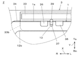
- FIG. 3 is a diagram of a display device according to a second embodiment of the present disclosure.
- the direction (first display board 1 side) in which the driver seated in the vehicle driver's seat is viewed from the display device 100 is set to each member.
- the front (front) and the opposite side (circuit board 4 side) are defined as “rear (rear)", and they are indicated by the arrows "Fr.” and “Re.” In the figure, respectively.
- “up”, “bottom”, “left”, and “right” will be appropriately described as arrows "To.”, "Bo.”, "L”, and “R” in the figure.
- the display device 100 for a vehicle according to the first embodiment will be described with reference to FIGS. 1 to 5.
- the display device 100 is mounted on a vehicle (for example, an automobile) and is configured as an instrument device that displays a predetermined measured amount (vehicle speed, etc.).
- the display device 100 includes a first display board (display board) 1, a second display board (covering member) 2, a case member 3, a circuit board 4, and a display (display member). It mainly has 5, a light guide body 6, a light source 7, a pointer 8, and a return 9.
- the first display plate 1 is formed by forming various printing layers on the front and back surfaces of a base material 11 made of a translucent synthetic resin (for example, polycarbonate) formed into a thin plate shape.
- the first display board 1 has a light-shielding layer 12 on which a light-shielding ink such as black is formed on the surface.
- the light-shielding layer 12 has an index unit 12a, a perspective window 12b, and an indicator 12c.
- the index unit 12a is formed by printing a light-shielding layer 12 on a design such as a scale or a number indicated by the pointer 8.
- the see-through window 12b is formed by punching out and printing a light-shielding layer 12 in a substantially rectangular shape at a position facing the display portion 51a of the display device 5.
- the indicator 12c is formed by printing the light-shielding layer 12 on the design of various operation lights and warning lights such as a turn and a high beam.
- the first display plate 1 has a first positioning hole 13 and a second positioning hole 14.
- the first positioning hole 13 is formed on the outer peripheral 1a on the upper side of the first display plate 1, and is formed in a U-shaped notch shape with the outer peripheral 1a side open.
- the first positioning hole 13 is a notch or slit having a constant width in the left-right direction (first direction) X.
- a total of two second positioning holes 14 are formed at the positions of the left and right outer circumferences 1b of the first display plate 1, respectively.
- the second positioning hole 14 is formed at a symmetrical position with respect to the first positioning hole 13.
- the second positioning hole 14 is a notch formed in a U shape with the outer circumference 1b side open.
- the second positioning hole 14 is a notch or slit having a constant width in the vertical direction (second direction) Y orthogonal to the horizontal direction X.
- the second display plate 2 is formed by forming various printing layers on the front and back surfaces of a base material 21 of a translucent synthetic resin (for example, polycarbonate) formed into a thin plate shape.
- the second display board 2 has a light-shielding layer 22 on which a light-shielding ink such as black is formed on the surface.
- the light-shielding layer 22 has a decorative indicator 22a.
- the decorative indicator 22a is formed by printing a light-shielding layer 22 on a substantially semicircular design.
- the light source 7 is mounted on the front side of the circuit board 4.
- the light source 7 has a first light source 71, a second light source 72, and a third light source 73.
- the first light source 71 and the second light source 72 are made of, for example, a surface mount type LED (Light Emitting Diode) having a predetermined color.
- the third light source 73 is composed of, for example, a surface mount type LED having three primary colors of RGB (RED, GREEN, BLUE).
- the light emitted by the first light source 71 causes the index unit 12a and the pointer 8 to emit light.
- the light emitted by the second light source 72 causes the indicator 12c to emit light.
- the light emitted by the third light source 73 causes the decorative indicator 22a to emit light via the light guide body 6.
- the case member 3 is made of a white synthetic resin (for example, polypropylene) and supports the first display plate 1 on the front surface.
- the case member 3 includes a first lighting chamber 31, a second lighting chamber 32, a third lighting chamber 33, an accommodating portion 34, a mounting portion 35, a receiving portion 36, and a first positioning protrusion (first positioning protrusion). It has a positioning portion) 37, a second positioning projection (second positioning portion) 38, and a third positioning projection 39.
- the first lighting chamber 31 is formed so as to surround the plurality of first light sources 71, and guides the light of the first light source 71 to the index unit 12a and the pointer 8.
- the second lighting chamber 32 is formed in a tubular shape so as to surround the second light source 72, and guides the light of the second light source 72 to the indicator 12c.
- the third lighting chamber 33 accommodates the light guide body 6 inside, and guides the light of the third light source 73 to the decoration indicator 22a.
- the third lighting chamber 33 is composed of a rear portion 33a and a front portion 33b of the case member 3.
- the rear portion 33a is formed in a tubular shape so as to surround the third light source 73, and is arranged at a position that does not support the first display plate 1.
- One end of the rear portion 33a comes into contact with the circuit board 4, and the other end extends forward to the same height as the first display plate 1.
- the wall on the display 5 side of the rear portion 33a is shared with the wall forming the tubular shape of the accommodating portion 34.
- the front portion 33b is continuously formed on the rear portion 33a, and projects forward from the front side of the rear portion 33a beyond the first display plate 1.
- a part of the front portion 33b extends toward the perspective window 12b in a direction parallel to the plane direction of the first display plate 1 in front of the first display plate 1, and the first display is in front of the first display plate 1. It is arranged so as to overlap the plate 1 and the accommodating portion 34. In this way, the front portion 33b is formed so as to cover a part of the first display plate 1 and a part of the accommodating portion 34 from the front.
- the front portion 33b has a tapered invitation portion (inclined portion) 33b1 that guides the first display plate 1 toward the receiving portion 36 on the surface on the back side of the first display plate 1.
- the second display board 2 is arranged so as to cover the front side of the front portion 33b.
- the front portion 33b supports the second display plate 2 behind.
- the accommodating portion 34 is formed in a rectangular tubular shape and accommodates the display 5 inside.
- the accommodating portion 34 is formed in a range larger than the range in which the front portion 33b covers a part of the accommodating portion 34.
- a part of the wall forming the front-rear direction of the accommodating portion 34 is shared with the wall on the display 5 side of the rear portion 33a.
- the mounting portion 35 is a front portion of the case member 3 and supports the first display plate 1 behind.
- the receiving portion 36 projects toward the display 5 from the wall of the rear portion 33a shared with the accommodating portion 34 at a position behind the front portion 33b.
- the receiving portions 36 are formed at two locations.
- the receiving portion 36 is arranged at a position behind the front portion 33b and behind the first display plate 1, and supports the back of the first display plate 1.
- the receiving portion 36 has a tapered invitation portion (inclined portion) 36a that guides the first display plate 1 to the front surface side of the receiving portion 36 on the surface of the tip of the first display plate 1 side.
- the outer circumference 1a of the first display plate 1 is sandwiched between the back of the front portion 33b and the front surface of the receiving portion 36.
- the first positioning protrusion 37 is a protrusion that fits into the first positioning hole 13 and positions the first display plate 1 in the left-right direction X.
- the first positioning protrusion 37 is formed between two receiving portions 36 at a position behind the front portion 33b and behind the front portion 33b, and is adjacent to the receiving portion 36.
- the first positioning projection 37 is formed so as to project from the wall of the rear portion 33a shared with the accommodating portion 34 toward the perspective window 12b or the display 5.
- the second positioning protrusion 38 is a protrusion that protrudes forward from the mounting portion 35 in a circular cross section.
- the second positioning protrusion 38 is a protrusion that fits into the second positioning hole 14 and positions Y in the vertical direction of the first display plate 1.
- the third positioning protrusion 39 is a protrusion that protrudes from behind the first positioning protrusion 37 toward the circuit board 4 in a circular cross section.
- the circuit board 4 is made of, for example, a hard wiring board in which a wiring pattern is applied to a glass epoxy base material, and electronic components are conductively connected (arranged) to the wiring pattern.
- Electronic components include, for example, a drive body that drives a pointer 8, a light source 7, a plurality of IC (Integrated circuit) chips 41, a resistor, a capacitor, and the like.
- the circuit board 4 has a hole 42 through which the third positioning projection 39 is inserted and fitted.
- the IC chip 41 is a thin rectangular microchip and is mounted on the back side of the circuit board 4.
- the IC chip 41 functions as a GDC (Graphics Display Controller: drawing control controller), and displays an image on the display 5 based on a control signal output from the IC chip 41.
- GDC Graphics Display Controller: drawing control controller
- the IC chip 41 has a function as a microcomputer, has a CPU (Central Processing Unit), a ROM (Read Only Memory), a RAM (Random Access Memory), etc., and has a vehicle speed from the vehicle's ECU (Electronic Control Unit).
- the engine speed, various vehicle information, navigation information, etc. are acquired, and based on the acquired information, predetermined arithmetic processing is executed according to the program written in the ROM, and the drive main body (not shown), the light source 7, the display 5, etc. To drive and control.
- the display 5 is arranged behind the first display board 1, and is a metal case that houses the liquid crystal display panel 51, the backlight unit 52 that transmits and illuminates the liquid crystal display panel 51, and the liquid crystal display panel 51 and the backlight unit 52. It is equipped with 53.
- the liquid crystal display panel 51 has a polarizing member attached to the front and rear surfaces of a TFT type color LCD cell, and can display various vehicle information such as a speedometer, an odometer, a fuel consumption meter, and a time as an image. A portion 51a is provided. The display unit 51a is visible to the viewer through the perspective window 12b.
- the light guide body 6 is made of a translucent synthetic resin (for example, acrylic) containing a light diffusing material.
- the light guide body 6 is housed in a third lighting chamber 33 and has a light receiving unit 61 and an emitting unit 62.
- the light receiving unit 61 is arranged at a position facing the third light source 73, and receives light from the third light source 73.
- the emitting unit 62 is arranged at a position facing the decoration indicator 22a, and emits the light incident on the light receiving unit 61 to the decoration indicator 22a.
- the pointer 8 has an indicator 81 made of a translucent resin (for example, polycarbonate) and a pointer cap 82 made of an opaque resin (for example, ABS).
- the pointer 8 is connected to the rotation shaft of the drive body, and the index unit 12a is instructed by the instruction unit 81.
- the drive main body is composed of a movable magnet type drive main body, a stepping motor, or the like, and is mounted behind the circuit board 4, and the rotation shaft projects forward.
- the display device 100 constitutes an analog tachometer by the pointer 8 and the index unit 12a.
- the dial 9 is made of a black synthetic resin (for example, polypropylene).
- the facing 9 is arranged in front of the first display board 1 and the second display board 2.
- the dial 9 exposes the visible region of the display device 100, that is, the pointer 8, the index unit 12a, the perspective window 12b, the indicator 12c, and the decorative indicator 22a.
- a transparent or translucent fluoroscopic panel (not shown) formed in a curved shape is arranged.
- the procedure for assembling the first display board 1 to the case member 3 will be described.
- the first display board 1 is arranged on the mounting portion 35.
- the first display board 1 is slid upward in the vertical direction Y.
- the outer circumference 1a is inserted behind the front portion 33b and guided to the receiving portion 36 by the invitation portion 33b1.
- the outer circumference 1a is guided to the front side of the receiving portion 36 by the invitation portion 36a, and is located between the back of the front portion 33b and the front surface of the receiving portion 36.
- the first positioning hole 13 is fitted into the first positioning projection 37.
- the outer peripheral 1a of the first display plate 1 can be fixed to the case member 3 behind the front portion 33b.
- the first display board 1 hangs down behind the front portion 33b, and it is possible to prevent an abnormal noise generated when the first display board 1 and the display 5 come into contact with each other. Further, by the invitation portion 33b1 and the invitation portion 36a, the outer circumference 1a of the first display plate 1 can be easily fixed to the case member 3 even in the dizziness work behind the third lighting chamber 33.
- the first display plate 1 has a vertical direction Y, which is a direction in which the outer peripheral portion 1a is slid to be sandwiched between the front portion 33b and the receiving portion 36, by the second positioning hole 14 and the second positioning projection 38. Since it is positioned, it is possible to prevent the outer circumference 1a of the first display plate 1 from coming off the receiving portion 36.
- the front portion 33b has a through hole (penetration portion) 33b2.
- the through hole 33b2 is a through hole formed at a position facing the receiving portion 36 so that the receiving portion 36 can be visually recognized from the front.
- the second display plate 2 covers the front surface side of the through hole 33b2.
- the first display plate 1 has a colored portion 15.
- the coloring portion 15 is a reflective ink such as white, which is a color similar to the material color of the case member 3 formed at a position facing the through hole 33b2 on the surface of the first display plate 1.
- the display device 5 which is a display means of the display device may be an organic EL (Electroluminescence) module.
- the second display board 2 covered the front side of the front portion 33b, a part of the facing 9 may extend to cover the front side of the front portion 33b.
- the present disclosure relates to a display device for a vehicle, and can be applied to, for example, a display device for a vehicle mounted on a moving body equipped with an automobile, a motorcycle, or an agricultural machine or a construction machine.
Landscapes
- Engineering & Computer Science (AREA)
- Chemical & Material Sciences (AREA)
- Combustion & Propulsion (AREA)
- Transportation (AREA)
- Mechanical Engineering (AREA)
- Physics & Mathematics (AREA)
- General Physics & Mathematics (AREA)
- Theoretical Computer Science (AREA)
- Instrument Panels (AREA)
- Details Of Measuring Devices (AREA)
Abstract
L'invention concerne un dispositif d'affichage qui permet de fixer une plaque d'affichage à un endroit dans lequel une partie de la plaque d'affichage est disposée derrière un élément de boîtier. La présente invention comprend, au moins, une plaque d'affichage en forme de plaque mince (1), et un élément de boîtier (3) destiné à soutenir la plaque d'affichage (1) depuis l'arrière, l'élément de boîtier (3) ayant : une partie avant (33b) qui fait saillie vers l'avant à partir de la plaque d'affichage (1) et recouvre le côté avant de la plaque d'affichage (1) ; une partie de réception (34) formée derrière la partie avant (33b) dans une plage plus grande que la plage dans laquelle la partie avant (33b) recouvre la plaque d'affichage (1) ; et une partie de réception (36) qui soutient la plaque d'affichage (1) depuis l'arrière de la partie avant (33b).
Priority Applications (1)
| Application Number | Priority Date | Filing Date | Title |
|---|---|---|---|
| JP2021520878A JP7514451B2 (ja) | 2019-05-23 | 2020-05-22 | 表示装置 |
Applications Claiming Priority (2)
| Application Number | Priority Date | Filing Date | Title |
|---|---|---|---|
| JP2019-096929 | 2019-05-23 | ||
| JP2019096929 | 2019-05-23 |
Publications (1)
| Publication Number | Publication Date |
|---|---|
| WO2020235682A1 true WO2020235682A1 (fr) | 2020-11-26 |
Family
ID=73459122
Family Applications (1)
| Application Number | Title | Priority Date | Filing Date |
|---|---|---|---|
| PCT/JP2020/020368 Ceased WO2020235682A1 (fr) | 2019-05-23 | 2020-05-22 | Dispositif d'affichage |
Country Status (2)
| Country | Link |
|---|---|
| JP (1) | JP7514451B2 (fr) |
| WO (1) | WO2020235682A1 (fr) |
Cited By (1)
| Publication number | Priority date | Publication date | Assignee | Title |
|---|---|---|---|---|
| JP2022160758A (ja) * | 2021-04-07 | 2022-10-20 | トヨタ車体株式会社 | 車両の内装部品 |
Citations (7)
| Publication number | Priority date | Publication date | Assignee | Title |
|---|---|---|---|---|
| JP2004327286A (ja) * | 2003-04-25 | 2004-11-18 | Nippon Seiki Co Ltd | スイッチ操作装置 |
| JP2005127893A (ja) * | 2003-10-24 | 2005-05-19 | Nippon Seiki Co Ltd | 車両用計器 |
| JP2007205730A (ja) * | 2006-01-31 | 2007-08-16 | Nippon Seiki Co Ltd | 計器装置 |
| JP2011242378A (ja) * | 2010-04-23 | 2011-12-01 | Nippon Seiki Co Ltd | 計器装置 |
| JP2013237284A (ja) * | 2012-05-11 | 2013-11-28 | Sumitomo Wiring Syst Ltd | インジケータを有する車両用内装部品 |
| JP2019020282A (ja) * | 2017-07-19 | 2019-02-07 | 日本精機株式会社 | 計器装置 |
| WO2019026544A1 (fr) * | 2017-08-04 | 2019-02-07 | 株式会社デンソー | Dispositif d'affichage pour véhicule |
Family Cites Families (1)
| Publication number | Priority date | Publication date | Assignee | Title |
|---|---|---|---|---|
| JP5522186B2 (ja) | 2012-02-22 | 2014-06-18 | 株式会社デンソー | 表示装置 |
-
2020
- 2020-05-22 JP JP2021520878A patent/JP7514451B2/ja active Active
- 2020-05-22 WO PCT/JP2020/020368 patent/WO2020235682A1/fr not_active Ceased
Patent Citations (7)
| Publication number | Priority date | Publication date | Assignee | Title |
|---|---|---|---|---|
| JP2004327286A (ja) * | 2003-04-25 | 2004-11-18 | Nippon Seiki Co Ltd | スイッチ操作装置 |
| JP2005127893A (ja) * | 2003-10-24 | 2005-05-19 | Nippon Seiki Co Ltd | 車両用計器 |
| JP2007205730A (ja) * | 2006-01-31 | 2007-08-16 | Nippon Seiki Co Ltd | 計器装置 |
| JP2011242378A (ja) * | 2010-04-23 | 2011-12-01 | Nippon Seiki Co Ltd | 計器装置 |
| JP2013237284A (ja) * | 2012-05-11 | 2013-11-28 | Sumitomo Wiring Syst Ltd | インジケータを有する車両用内装部品 |
| JP2019020282A (ja) * | 2017-07-19 | 2019-02-07 | 日本精機株式会社 | 計器装置 |
| WO2019026544A1 (fr) * | 2017-08-04 | 2019-02-07 | 株式会社デンソー | Dispositif d'affichage pour véhicule |
Cited By (2)
| Publication number | Priority date | Publication date | Assignee | Title |
|---|---|---|---|---|
| JP2022160758A (ja) * | 2021-04-07 | 2022-10-20 | トヨタ車体株式会社 | 車両の内装部品 |
| JP7476839B2 (ja) | 2021-04-07 | 2024-05-01 | トヨタ車体株式会社 | 車両の内装部品 |
Also Published As
| Publication number | Publication date |
|---|---|
| JPWO2020235682A1 (fr) | 2020-11-26 |
| JP7514451B2 (ja) | 2024-07-11 |
Similar Documents
| Publication | Publication Date | Title |
|---|---|---|
| US9664541B2 (en) | Vehicle instrument | |
| JP5370658B2 (ja) | 計器照明装置 | |
| JP2010276498A5 (fr) | ||
| JP7514451B2 (ja) | 表示装置 | |
| JP5510076B2 (ja) | 表示装置 | |
| CN109203994B (zh) | 车辆显示装置 | |
| JP7269534B2 (ja) | 表示装置 | |
| WO2018139432A1 (fr) | Dispositif d'affichage | |
| CN109211295B (zh) | 车辆显示装置 | |
| JP4513051B2 (ja) | 車両用計器 | |
| JP3912373B2 (ja) | 計器装置 | |
| JP6997411B2 (ja) | 表示装置 | |
| JP5134491B2 (ja) | 計器装置 | |
| JP7041840B2 (ja) | 表示装置 | |
| JP2009068859A (ja) | 表示装置 | |
| JP6338087B2 (ja) | 表示装置 | |
| JP6894780B2 (ja) | 車両表示装置 | |
| JP7180438B2 (ja) | 車両用の計器装置 | |
| JP2010107267A (ja) | 車両用表示装置 | |
| JP7468285B2 (ja) | 表示装置 | |
| JP2020111085A (ja) | 表示装置 | |
| JP7298602B2 (ja) | 表示装置 | |
| CN109203993B (zh) | 车辆显示装置 | |
| JP2019045210A (ja) | 表示装置 | |
| JP2022055417A (ja) | 表示装置 |
Legal Events
| Date | Code | Title | Description |
|---|---|---|---|
| 121 | Ep: the epo has been informed by wipo that ep was designated in this application |
Ref document number: 20808702 Country of ref document: EP Kind code of ref document: A1 |
|
| ENP | Entry into the national phase |
Ref document number: 2021520878 Country of ref document: JP Kind code of ref document: A |
|
| NENP | Non-entry into the national phase |
Ref country code: DE |
|
| 122 | Ep: pct application non-entry in european phase |
Ref document number: 20808702 Country of ref document: EP Kind code of ref document: A1 |