WO2020235948A1 - Scanner intra-buccal tridimensionnel - Google Patents
Scanner intra-buccal tridimensionnel Download PDFInfo
- Publication number
- WO2020235948A1 WO2020235948A1 PCT/KR2020/006652 KR2020006652W WO2020235948A1 WO 2020235948 A1 WO2020235948 A1 WO 2020235948A1 KR 2020006652 W KR2020006652 W KR 2020006652W WO 2020235948 A1 WO2020235948 A1 WO 2020235948A1
- Authority
- WO
- WIPO (PCT)
- Prior art keywords
- case
- light
- camera
- oral cavity
- incident
- Prior art date
- Legal status (The legal status is an assumption and is not a legal conclusion. Google has not performed a legal analysis and makes no representation as to the accuracy of the status listed.)
- Ceased
Links
Images





Classifications
-
- A—HUMAN NECESSITIES
- A61—MEDICAL OR VETERINARY SCIENCE; HYGIENE
- A61C—DENTISTRY; APPARATUS OR METHODS FOR ORAL OR DENTAL HYGIENE
- A61C9/00—Impression cups, i.e. impression trays; Impression methods
- A61C9/004—Means or methods for taking digitized impressions
- A61C9/0046—Data acquisition means or methods
- A61C9/0053—Optical means or methods, e.g. scanning the teeth by a laser or light beam
-
- A—HUMAN NECESSITIES
- A61—MEDICAL OR VETERINARY SCIENCE; HYGIENE
- A61B—DIAGNOSIS; SURGERY; IDENTIFICATION
- A61B1/00—Instruments for performing medical examinations of the interior of cavities or tubes of the body by visual or photographical inspection, e.g. endoscopes; Illuminating arrangements therefor
- A61B1/00163—Optical arrangements
- A61B1/00172—Optical arrangements with means for scanning
-
- A—HUMAN NECESSITIES
- A61—MEDICAL OR VETERINARY SCIENCE; HYGIENE
- A61B—DIAGNOSIS; SURGERY; IDENTIFICATION
- A61B1/00—Instruments for performing medical examinations of the interior of cavities or tubes of the body by visual or photographical inspection, e.g. endoscopes; Illuminating arrangements therefor
- A61B1/00163—Optical arrangements
- A61B1/00186—Optical arrangements with imaging filters
-
- A—HUMAN NECESSITIES
- A61—MEDICAL OR VETERINARY SCIENCE; HYGIENE
- A61B—DIAGNOSIS; SURGERY; IDENTIFICATION
- A61B1/00—Instruments for performing medical examinations of the interior of cavities or tubes of the body by visual or photographical inspection, e.g. endoscopes; Illuminating arrangements therefor
- A61B1/24—Instruments for performing medical examinations of the interior of cavities or tubes of the body by visual or photographical inspection, e.g. endoscopes; Illuminating arrangements therefor for the mouth, i.e. stomatoscopes, e.g. with tongue depressors; Instruments for opening or keeping open the mouth
-
- A—HUMAN NECESSITIES
- A61—MEDICAL OR VETERINARY SCIENCE; HYGIENE
- A61B—DIAGNOSIS; SURGERY; IDENTIFICATION
- A61B5/00—Measuring for diagnostic purposes; Identification of persons
- A61B5/0059—Measuring for diagnostic purposes; Identification of persons using light, e.g. diagnosis by transillumination, diascopy, fluorescence
- A61B5/0062—Arrangements for scanning
-
- A—HUMAN NECESSITIES
- A61—MEDICAL OR VETERINARY SCIENCE; HYGIENE
- A61B—DIAGNOSIS; SURGERY; IDENTIFICATION
- A61B5/00—Measuring for diagnostic purposes; Identification of persons
- A61B5/0059—Measuring for diagnostic purposes; Identification of persons using light, e.g. diagnosis by transillumination, diascopy, fluorescence
- A61B5/0073—Measuring for diagnostic purposes; Identification of persons using light, e.g. diagnosis by transillumination, diascopy, fluorescence by tomography, i.e. reconstruction of 3D images from 2D projections
-
- A—HUMAN NECESSITIES
- A61—MEDICAL OR VETERINARY SCIENCE; HYGIENE
- A61B—DIAGNOSIS; SURGERY; IDENTIFICATION
- A61B5/00—Measuring for diagnostic purposes; Identification of persons
- A61B5/0059—Measuring for diagnostic purposes; Identification of persons using light, e.g. diagnosis by transillumination, diascopy, fluorescence
- A61B5/0082—Measuring for diagnostic purposes; Identification of persons using light, e.g. diagnosis by transillumination, diascopy, fluorescence adapted for particular medical purposes
- A61B5/0088—Measuring for diagnostic purposes; Identification of persons using light, e.g. diagnosis by transillumination, diascopy, fluorescence adapted for particular medical purposes for oral or dental tissue
Definitions
- the present invention relates to a three-dimensional oral scanner (3-DIMENSIONAL INTRAORAL SCANNER), and more particularly, to a three-dimensional oral scanner that can easily measure a measurement object through at least one camera.
- an oral scanner is an optical device for generating a three-dimensional scanning model of a dental row by being inserted into the oral cavity of a dental patient and scanning teeth in a non-contact manner.
- 1 is a schematic diagram of obtaining 3D information using an oral scanner and a schematic diagram of applying a polarizing plate.
- structured light is projected onto the tooth, which is the measurement object O, and the light reflected therefrom. Takes a method of obtaining 3D data from it.
- the light generated from the light generating unit 170 passes through the projection lens 171 and is reflected from the inside of the oral cavity including the tooth that is the measurement object O, and then enters the inside through the camera lens 121.
- 3D data is obtained through the imaging sensor 130.
- the projected structured light is accurately projected onto the tooth, which is the surface of the object O, and obtained.
- the projected light is not a surface reflection material such as a gypsum model, but an inner reflection material such as a tooth, the projected light of the object is transferred not only to the surface of the object to be measured, but also to the inside of the material.
- accurate 3D data could not be obtained due to the transmitted and reflected effect.
- the first polarizing plate 180a is provided in the projection path before the light is projected from the light generating unit 170 to the measurement object O
- a second polarizing plate 180b should be provided in the incident path before being reflected from the measurement object O and incident on the camera lens 121, which should be provided with at least two polarizing plates 180a, 180b in the case of a single camera.
- the stereo vision method it means that at least three polarizing plates must be provided, and the overall slim design of the product leads to a very difficult problem.
- another object of the present invention is to provide a 3D oral scanner capable of clearer and more precise measurement by removing internal reflection light by an internal reflective material such as a tooth in measuring a measurement object.
- another object of the present invention is to provide a 3D oral scanner capable of providing an optimal design that does not generate ghost images or noise while enabling slim manufacturing of a tip case provided to be retractable into the oral cavity of a patient.
- the three-dimensional oral scanner according to an embodiment of the present invention for achieving the above object is capable of being inserted and withdrawn into the oral cavity, and the appearance of the inside of the oral cavity (hereinafter, abbreviated as'image') through one end is broadly A case in which an opening is formed so as to enter the case in a form, at least one camera disposed inside the case and disposed to pass light incident through the opening of the case, and disposed between the at least one camera A light projector that irradiates light into the oral cavity through the opening, and a single polarization filter positioned between the at least one camera and the opening, but spaced apart by a set distance (d) from the front end of the at least one camera Includes.
- the set distance (d) may be set to a distance in which a projection angle of view projected from the light projector into the oral cavity and an image angle of view reflected from the oral cavity and incident to the at least one camera do not overlap each other.
- the set distance (d) may be set so that light projected from the optical projector into the oral cavity is not incident to the at least one camera in the form of reflected light reflected by the single polarizing filter.
- the set distance (d) is assumed that the upper and lower widths and the left and right widths (hereinafter, abbreviated as'full size') of the single polarizing filter increase as the single polarizing filter approaches the at least one camera.
- the total size of the single polarization filter may be set at the smallest position.
- the set distance (d) may satisfy the following equation.
- the case includes a body case in which the at least one camera and various electric components for driving the same are embedded, and a tip case coupled to one end of the body case and having the opening, wherein the single polarization filter , It may be installed so that the set distance (d) is located in the tip case.
- an upper rib and a lower rib may be integrally formed in the tip case in which the upper and lower ends of the single polarizing filter are inserted and installed.
- the tip case is manufactured with various specifications so as to have a darkroom having a different length according to the length measured from one end to the other end, where the set distance (d) is located, and is separated from one end of the main body case It may be detachably coupled to one end of the main body case to facilitate replacement.
- the single polarization filter may be previously fixed at different locations satisfying the set distance d according to the length of the dark room.
- An optical projector that irradiates light into the interior and a projection angle of view that is positioned between the at least one camera and the opening, and is projected from the optical projector into the oral cavity, and an image reflected from the oral cavity and incident to at least one camera It includes a single polarization filter arranged horizontally so that the angle of view does not overlap each other.
- Another embodiment of the 3D oral scanner according to the present invention is a case provided with a reflective member that can be inserted into and withdrawn into the oral cavity and reflects incident light incident into the body and exit light emitted from the body, the case A pair of stereo cameras disposed inside of the case and disposed to pass incident light incident through the reflective member of the case in different paths, respectively, and disposed between the pair of stereo cameras and inside the oral cavity through the reflective member And a single polarization filter positioned between the pair of stereo cameras and the reflective member, and disposed in parallel with the light projector, and an optical projector that irradiates the outgoing light.
- the imaging board to which the imaging sensor is attached is coupled to the inner wall of the main body case, and is provided to refract or change the incident light, thereby enabling a slim manufacturing of the main body case to be easily gripped by the user.
- 1 is a schematic diagram of obtaining 3D information using an oral scanner and a schematic diagram of applying a polarizing plate
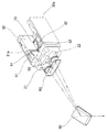
- FIG. 2 is a perspective view showing an embodiment of a 3D oral scanner according to the present invention
- FIG. 2 is an exploded perspective view of FIG. 2,
- FIG. 4 is a cross-sectional view taken along line A-A of FIG. 2,
- FIG. 5 is a perspective view showing an optical path using a pair of stereo cameras in the configuration of FIG. 2,
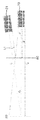
- FIG. 6 is a schematic plan view for explaining the position design of a single polarization filter in the configuration of FIG. 2,
- FIG. 7 is a schematic plan view showing the image angle of view, the projection angle of view, and the triangulation angle of FIG. 6;
- FIG. 8 is a schematic diagram visually showing a fixing part of at least one camera and a light projector, and a fixing part of a single polarizing filter in the configuration of a 3D oral scanner according to an embodiment of the present invention
- FIG. 9 is a schematic diagram showing an ideal installation model of at least one camera and an optical projector in the configuration of FIG. 8,
- FIG. 10 is a schematic diagram illustrating various types of tolerances when installing at least one camera and an optical projector in the configuration of FIG. 8,
- FIG. 11 is a schematic diagram showing the effect of using a single polarization filter
- FIG. 12 is a schematic diagram showing another effect when a single polarization filter is used.
- 31b,32b imaging sensor 41,42: light path changing mirror
- optical projector 80 single polarizing filter
- FIG. 2 is a perspective view showing an embodiment of a 3D oral scanner according to the present invention
- FIG. 3 is an exploded perspective view of FIG. 2
- FIG. 4 is a cross-sectional view taken along line AA of FIG. 2
- FIG. 5 is A perspective view showing an optical path using a pair of stereo cameras in the configuration
- FIG. 6 is a schematic plan view for explaining the position design of a single polarization filter in the configuration of FIG. 2.
- An embodiment of the 3D oral scanner according to the present invention includes a case 10 capable of being inserted and withdrawn into the oral cavity.
- At least one camera 20 may be disposed inside the case 10. That is, at least one camera 20, although not shown in the drawing, is a single camera 20 and may be disposed inside the case 10. In addition, at least one camera 20 may be disposed inside the case 10 as a pair of stereo cameras 20, as shown in FIG. 3.
- the width direction of the case 10 is to pass light incident from one end of the case 10 through different paths. Can be arranged spaced apart.
- at least one camera 90 is disposed inside the case 10, but it should be noted that the application of the single camera 20 is not completely excluded.
- the term'light' means, in a broad sense, light in the visible light range that can be seen by the human eye, but refers to light in the infrared or ultraviolet light that can be observed using a special optical device. It may be a concept that includes all, and in a narrow sense, it may refer to a shape inside the oral cavity of a patient to be measured (hereinafter, abbreviated as'burn').
- the case 10 may be provided with an opening 16 that is opened so that an image is introduced into the interior in the form of light through one end.
- the opening 16 may be an inlet through which light from the outside of the case 10 flows into the interior of the case 10.
- Light incident through the opening 16 is transmitted to each of the pair of stereo cameras 20 while forming different light paths, respectively.
- the light transmitted through the pair of stereo cameras 20 is photographed through imaging sensors 31b and 32b provided in imaging boards 31a and 32a to be described later.
- the pair of stereo cameras 20 may include at least two transmissive lenses capable of adjusting focus on an image in the oral cavity.
- an embodiment of the 3D oral scanner 1 according to the present invention is an imaging board 31a having an imaging sensor 31b and 32b for imaging light transmitted through a pair of stereo cameras 20, respectively. ,32a) may be further included.
- a camera control board mounted with an electric component for controlling the operation of a pair of stereo cameras 20 and an electric field for processing the scanned image A scanning control board on which a component is mounted may be further included.
- the case 10 is a pair of stereo cameras 20, imaging boards 31a and 32a, a camera control board (not shown), and a scanning control board (not shown), as referenced in FIGS. 2 to 4. ) Serves to provide a predetermined space to be embedded.
- the case 10 is provided on the upper side of the lower case 12 and the lower case 12 in which a predetermined space is formed in which the components are embedded, as shown in FIG. 3, the lower case 12 ) Is detachably coupled to the body case 11 made of an upper case 13 covering the above configurations.
- the case 10 is coupled to one end of the main body case 11, the above-described opening 16 is formed, and the light incident into the body case 11 through the opening 16 and the opening 16
- the tip case 14 may further include a tip case 14 in which the input/output path part 17 for guiding the light emitted from the inside of the main body case 11 is formed.
- the inside of the tip case 14 is provided in the form of a darkroom 85 in which incident light and emitted light, which will be described later, are not leaked, and the darkroom 85 is formed to have a different length according to the age group and oral characteristics of the patient to be measured. I can.
- the total length of the tip case 14 is relatively small, and in this case, the length of the darkroom 85 may also be made relatively small.
- the total length of the tip case 14 is relatively large, and the length of the darkroom 85 in this case may also be made relatively large.
- the tip case 14 is coupled to one end of the main body case 11, and a dark room of a different length according to the length measured from one end to the other end so that it can be easily separated and replaced according to the patient to be measured. It is manufactured in various specifications so as to be provided, and may be detachably coupled to one end of the main body case 11.
- a single polarizing filter 80 which will be described later, is installed, and the length of the dark room 85 is within a limit that satisfies the set distance d for setting the position of the single polarizing filter 85, which will be described later. It can be manufactured in various lengths, and at this time, the single polarizing filter 85 may be fixed in a different position satisfying the above setting distance d, so that the tip case 14 of various specifications may be replaced and used.
- the light incident into the body case 11 through the opening 16 refers to an image of the inside of the patient's oral cavity, and the body case through the opening 16 (11)
- Light emitted from the inside refers to irradiation light radiated from the light projector 70 to be described later.
- a light guide structure in which the incident light and the exit light are easily irradiated to the inside and outside of the case 10 may be formed inside the tip case 14.
- the opening 16 is formed to be opened in one direction orthogonal to the longitudinal direction of the tip case 14, and a reflective member 60 to be described later may be disposed in the opening 16.
- the front ends of the pair of stereo cameras 20, as described above, are disposed to converge at the tip case 14 side, and may be disposed to overlap the tip case 14 by a predetermined distance.
- the rear ends of the pair of stereo cameras 20 may be provided to be connected to the camera mounting unit 50 fixed inside the body case 11.
- an embodiment of the 3D oral scanner 1 according to the present invention is disposed inside the case 10, between a pair of stereo cameras 20
- a light projector 70 that emits predetermined emission light through the case 10 and irradiates the emission light through an opening 16 formed at the front end of the tip case 14 of the case 10 may be further included.
- one embodiment of the three-dimensional oral scanner 1 according to the present invention is located between a pair of stereo cameras 20 and the opening 16, a pair
- the stereo camera 20 may further include a single polarization filter 80 positioned at a position spaced apart from the front end by a set distance (d).
- the configurations as described above are arranged inside the case 10, but from the user's side, the 3D oral scanner 1 according to the present invention is easily gripped.
- the slim design of the main body case 11 is related to the arrangement design of the imaging sensors 31b and 32b separately provided for each incident light incident through each of the pair of stereo cameras 20, as described later.
- the slim design of the tip case 14 is related to the arrangement design of the single polarizing filter 80 as described later.
- a camera mounting unit 50 may be disposed to form an optical waveguide that is a path of incident light transmitted through the pair of stereo cameras 20 or emitted light emitted from the light projector 70.
- the optical waveguide formed in the camera mounting unit 50 may be provided in a dark room shape so that incident light incident from the opening 16 and output light irradiated from the light projector 70 are partitioned from each other and do not affect each other.
- the optical waveguide is incident through an emission light path part 53 providing an optical path to the tip case 14 side of the emitted light irradiated from the optical protector, and one of the pair of stereo cameras 20
- One side incident light path unit 51 providing an optical path of the incident light
- the other side incident light path unit 52 providing an optical path of incident light incident through the other side of the pair of stereo cameras 20. I can.
- the exit light path portion 53, the incident light path portion 51 on the one side, and the incident light path portion 52 on the other side are provided so as to be partitioned from each other, so that the light of each path may not affect each other at all.
- the optical protector is located at the center of the other end of the pair of stereo cameras 20 arranged to be spaced apart from each other by a predetermined distance in the width direction of the case 10, and the exit light path part 53 is one side incident light path part. It may be formed between 51 and the other side incident light path portion 52.
- One side incident light path part 51 and the other side incident light path part 52 are formed to match the longitudinal direction of a stereo camera corresponding to each so that the incident light incident from the pair of stereo cameras 20 is transmitted. It may be formed to open to one side and the other side of the mounting part 50.
- the imaging boards 31a and 32a in which the imaging sensors 31b and 32b are integrated may be vertically disposed so as to be in close contact with one side wall in the width direction and the other side wall in the width direction of the case 10.
- the imaging boards 31a and 32a of one side are disposed to be in close contact with one side of the camera mounting unit 50, and may be disposed between one side wall in the width direction of the case 10.
- the imaging boards 31a and 32a on the other side may be disposed between the other side walls in the width direction of the case 10 even if they are arranged to be in close contact with the other side of the camera mounting unit 50.
- the imaging boards 31a and 32a on one side are provided so that the imaging sensors 31b and 32b integrated therein are exposed to the incident light path part 51 on the other side, and the imaging boards 31a and 32a on the other side are integrated therein.
- the imaging sensors 31b and 32b may be provided to be exposed to the other incident light path part 52.
- One of the pair of optical path changing mirrors 41 and 42 transmits the incident light transmitted through the incident light path portion 51 to the imaging sensors 31b and 32b integrated on the imaging boards 31a and 32a on one side.
- One side of the light path changing mirror 41 that changes the path of the incident light to be irradiated, and the other of the pair of light path changing mirrors 41, 42, the other side of the incident light transmitted through the other side incident light path unit 52 It may be the other optical path changing mirror 42 that changes the path of the incident light so as to be irradiated to the imaging sensors 31b and 32b integrated on the imaging boards 31a and 32a of FIG.
- the pair of optical path changing mirrors 41 and 42 herein may include a total reflection mirror capable of total reflection of light. However, it is not necessarily limited to the total reflection mirror, and any optical element capable of total reflection may be included.
- An embodiment of the 3D oral scanner 1 according to the present invention is to secure 3D image data of a patient's oral cavity (ie, an image) using a pair of stereo cameras 20.
- one end of the pair of stereo cameras 20 (referring to the direction in which the tip case 14 is provided in the drawing) includes a reflective member 60 provided in one opening 16, respectively.
- the other end of the pair of stereo cameras 20 (referring to the direction in which the light projector 70 is provided in the drawing) transmits incident light transmitted through each in a linear direction. It must have a structure that transmits it.
- the pair of imaging boards 31a and 32a should be disposed to be spaced apart in the width direction of the case 10 so as to be orthogonal to the straight direction of the other end of each of the pair of stereo cameras 20.
- the thickness of the main body case 11 in the width direction may be increased by the length of the pair of imaging boards 31a and 32a.
- the incident light path portions 51 and 52 are formed to be opened to one side and the other side of the camera mounting unit 50, respectively.
- the mounting positions of the imaging boards 31a and 32a are vertically disposed between one side and the other side of the camera mounting unit 50 and one side wall and the other side wall of the case 10, and a pair of stereo cameras 20
- the body case 11 is slimmed so that the measurer can easily grip and use only with the thumb, forefinger, and middle finger. Can be formed.
- the pair of optical path changing mirrors 41 and 42 are each of the imaging sensors 31b and 32b in which incident light transmitted through the pair of stereo cameras 20 is provided on the pair of imaging boards 31a and 32a. It may be disposed to have a reflector surface of an angle incident on one surface of the.
- the pair of optical path changing mirrors 41 and 42 may have a reflector surface inclined with respect to the longitudinal direction of the case 10. That is, the light path changing mirror 41 on one side is refracted by the reflector surface of the light path changing mirror 41 after the incident light transmitted through the stereo camera 21 is incident through the incident light path unit 51 on the one side. As a result, it may be provided to irradiate the imaging sensors 31b and 32b of one side of the imaging board 31a.
- the other optical path changing mirror 42 is refracted by the reflector surface of the other optical path changing mirror 42 after incident light transmitted through the other stereo camera 22 is incident through the other incident light path part 52 It can be provided to be irradiated to the imaging sensors (31b, 32b) of the other side of the imaging board (31b).
- FIG. 6 is a schematic plan view for explaining the position design of a single polarization filter in the configuration of FIG. 2
- FIG. 7 is a schematic plan view showing the image field of view 92a and 92b, the projection angle of view 91, and the triangulation angle of FIG. .
- a pair of stereo cameras 20 on the front end side of the main body case 11 is a tip case 14
- the light projector 70 may be provided so as to overlap a predetermined length toward the provided side, and to emit light through a pair of stereo cameras 20.
- a single polarizing filter 80 is provided to remove the internal reflection light of the measurement object 100 made of an internal reflection material such as teeth and filter only the surface reflection light to pass through. Can be.
- the single polarization filter 80 may be installed to be positioned in the tip case 14 of the case 10.
- an upper installation rib (not shown) and a lower installation rib 81 may be integrally formed. That is, the single polarization filter 80 may be installed by fitting the upper and lower ends to the upper and lower ribs 81 integrally formed in the tip case 14.
- the single polarization filter 80 is located inside the tip case 14 corresponding between the pair of stereo cameras 20 and the opening 16, and a set distance (d) from the front end of the pair of stereo cameras 20 ) Can be located in a spaced position.
- the single polarization filter 80 is a projection angle of view 91 that the light emitted by the light projector 70 projects and the light reflected from the measurement object 100, as shown in FIG. 6. It is preferable that the set distance (d) is set to a distance in which the two image viewing angles 92a and 92b respectively incident on the pair of stereo cameras 20 do not overlap each other.
- the light emitted from the optical projector 70 passes through the single polarizing filter 80 and then passes through the opening 16 to the inside of the patient's oral cavity where the measurement object 100 is positioned, as shown in FIG. 6. It is projected, and the maximum area through which the light emitted from the light projector 70 passes through the single polarization filter 80 may be defined as the projection angle of view 91 as described above.
- the light emitted from the light projector 70 and projected into the oral cavity of the patient is reflected from the object to be measured 100, and then flows into the tip case 14 through the opening 16 again. It is incident to each of a pair of stereo cameras 20 spaced apart in the width direction of the case 11, where the maximum area transmitted through the single polarization filter 80 when incident to each of the pair of stereo cameras 20 As described above, can be defined as the image field of view 92a and 92b.
- the position where the single polarization filter 80 is installed is set to a position where the projection angle of view 91 and the image view angles 92a and 92b overlap each other, the light projected from the light projector 70 is transmitted to the single polarization filter 80 ) May be reflected by itself from the transmission surface and incident on the pair of stereo cameras 20.
- the image acquired through the imaging sensors 31b and 32b may generate a so-called ghost image or noise in which a spot brighter than the surrounding image is generated.
- the image viewing angles 92a and 92b may be designed to set the set distance d at a position where they do not overlap each other.
- the set distance (d) defining the position of the single polarizing filter 80 is a pair of reflected light reflected by the single polarizing filter 80 from the light projected into the oral cavity from the optical projector 70 It may be set not to be incident to each of the stereo cameras.
- the set distance (d) is sufficient if the projection angle of view 91 and the image angles of view 92a and 92b are set to position the single polarization filter 80 in a range where they do not overlap each other, so a single polarization filter ( 80) may be positioned as close as possible to the front end of the pair of stereo cameras 20.
- a single polarization filter ( 80) may be positioned as close as possible to the front end of the pair of stereo cameras 20.
- the size of the single polarization filter 80 when a single camera is applied, at least the size of the single polarization filter 80 is physically the above-described projection angle of view 91 and the image angle of view (any of 92a and 92b of FIG. 6).
- One reference is required to be larger than the size of the single camera, and when the single polarization filter 80 is designed to be positioned as close as possible to the front end of the single camera, an increase in the width direction is inevitably expected.
- a pair of stereo cameras 20 are used in the main body case. It is installed in the width direction of (11), but the front end of the pair of stereo cameras 20 is set to overlap with the tip case 14.
- the single polarization filter 80 should be manufactured at least in a size capable of implementing the image field of view (92a, 92b). As described above, the single polarization filter 80 is as much as possible toward the pair of stereo cameras 20. In the case of the close design, the size in the width direction must be increased inevitably, and thus a problem of hindering the slim design of the tip case 14 occurs.
- the set distance (d) of the single polarizing filter 80, the single polarizing filter 80 is a pair Assuming that the upper and lower widths and the left and right widths (hereinafter, abbreviated as'full size') of the single polarizing filter 80 increase as they approach toward the stereo camera 20, the total size of the single polarizing filter 80 Can be set in the smallest position.
- the single polarization filter 80 even if the single polarization filter 80 is approached to a pair of stereo cameras 20 to have a minimum separation distance, the single polarization filter 80 It should be set to a location where there is no mechanical or structural interference between the and surrounding components.
- the optimal setting distance d of the single polarization filter 80 may be set to satisfy the following equation, as shown in FIG. 7.
- d is the set distance
- D is the aperture of one camera lens
- the single polarization filter 80 can be positioned close to a minimum distance as long as there is no mechanical interference with the pair of stereo cameras 20. You will be able to.
- the single polarization filter 80 is close to the pair of stereo cameras 20, there is a problem that the overall size increases, so even in this case, the effect of slim manufacturing in an embodiment of the present invention. It should be designed in consideration of
- D is the aperture of the camera lens 21 on one side, and the increase in D means that the set distance d should be designed to be smaller, and becomes an impediment to the slim design. Therefore, it is desirable to design D to the minimum as possible, and the optical projector 70 and the pair of stereo cameras 21 and 22 each have to prioritize an optimal structural design in which the instrument interference does not occur.
- the direct reflected light L1 is transmitted through the single polarizing filter 80 forming the projection angle of view 91 to the camera 21 It must satisfy the condition not to penetrate into
- an increase in the aperture D of the camera lens 21 leads to an increase in the image field of view 92b, and in this case, the projection angle of view 91 and the image field of view 92b may overlap each other, and the set distance ( d) should be designed to be smaller.
- Equation 1 described above presents a theoretical background for deriving an optimal set distance d of a single polarization filter 80 capable of implementing all of these purposes.
- the reflective member 60 may be provided in the opening 16 formed in the tip case 14 as described above.
- the reflective member 60 serves to reflect incident light incident into the body case 11 and outgoing light emitted from the body case 11 through a predetermined path.
- the reflective member 60 may be provided in the form of a mirror or a prism.
- the reflective member 60 facilitates photographing through a pair of stereo cameras 20 through an opening 16 formed to be opened in one direction orthogonal to the longitudinal direction of the case 10.
- the single polarization filter 80 may be disposed between the pair of stereo cameras 20 and the reflective member 60, and may be disposed parallel to the light projector 70.
- the meaning that the single polarization filter 80 is disposed in parallel with the optical projector 70 means that each polarization filter is provided for each exit path of the exit light from the conventional optical projector 70 and the incident path of the incident light to the camera lens, This means that it has the advantage of eliminating the complicated process of designing the position of each polarization filter very precisely to reduce polarization efficiency.
- the measurer presses the operation button 15 provided on the upper part of the case 10 in order to measure into the patient's oral cavity using an embodiment of the 3D oral scanner 1 according to the present invention.
- the light emitted from the light projector 70 is irradiated.
- the outgoing light irradiated from the optical projector 70 is sequentially passed through the outgoing light path part 53 of the optical waveguides formed in the camera mounting part 50 and the in/out light path part 17 formed in the tip case 14 It is irradiated toward the opening 16 and is irradiated into the oral cavity of the patient through the opening 16 by the reflective member 60.
- the pair of stereo cameras 20 are operated by the operator pressing the operation button 15, so that two images having the same focus at any one point of the image You can get the data.
- the oral image of the patient exists in the form of light by the emitted light, and contrary to the emitted light, it is sequentially incident into the tip case 14 through the opening 16, and the path through the reflective member 60 Is changed, and a corresponding incident light path part 51 among the above-described input/output light path part 17, a corresponding stereo camera, and an optical waveguide with a pair of camera lenses that substantially photograph the reflective surface of the reflective member 60 52).
- two predetermined image data can be simultaneously secured. Based on the two image data secured in this way, 3D data on the oral image of the patient can be easily secured.
- FIG. 8 is a schematic diagram showing visually a fixing part of at least one camera and a light projector and a fixing part of a single polarizing filter among the configurations of a 3D oral scanner according to an embodiment of the present invention
- FIG. 9 is It is a schematic diagram showing an ideal installation model of at least one camera and an optical projector
- FIG. 10 is a various schematic diagram illustrating the occurrence of tolerances when installing at least one camera and an optical projector among the configurations of FIG. 8, and
- FIG. 11 is a single polarization
- FIG. 12 is a schematic diagram showing another effect of using a single polarization filter.
- FIG. 8 to 12 are schematic diagrams for explaining an effective aspect of a 3D oral scanner according to an embodiment of the present invention, and as shown in FIG. 8, a stereo camera provided inside the body case 14 ( 21) and the other side stereo camera 22, the optical projector 70 therebetween, and the single polarization filter 80, respectively, the lower end of each of the preset fixed position (reference numerals 21a, 21b, 22a, 22b, 70a in Fig. 8, 70b, and 80a, 80b) are most preferred to be installed without tolerances.
- the projection angle of view 91 and the object to be measured 100 are projected by the light emitted by the light projector 70.
- an assembly tolerance occurs in the other stereo camera 22, as referenced in FIG. 10(a), or as referenced in FIG. 10(b), one stereo camera 21
- An assembly tolerance may occur in, and as shown in FIG. 10(c), an assembly tolerance may occur only in the optical projector 70, and as shown in FIG. 10(d), one stereo camera 21 )
- the other side stereo camera 22 may have an assembly tolerance.
- the single polarization filter 80 as in the embodiment of the present invention is not applied and polarization filters are applied for each, the precision of the measured value is lowered due to the assembly tolerance of the above three configurations. Will occur.
- the measurement object is measured by mechanical tolerances with polarization filters corresponding to both stereo cameras 21 and the other stereo camera 22.
- the reflected light through is bound to be (100-@)%.
- the projection angle of view of the light projector 70 and the projection angle of view are similar to the shaded portions respectively displayed on the image field of view and the projection angle of view. Since the angles of the image field of view are all the same, it can be seen that the efficiency of the projected light and the reflected light is also the same.
- the projection angle of view of the optical projector 70 and the image angle of view by the one stereo camera 21 and the other stereo camera 22 are sized according to the above equation, and the area of the single polarization filter 80 is Because it does not deviate, it has the advantage of greatly improving the reliability.
- the present invention provides a 3D oral scanner capable of manufacturing a slim body case so that it is possible to secure 3D image data at the same time as measuring an object to be measured, as well as to facilitate gripping by a user.
Landscapes
- Health & Medical Sciences (AREA)
- Life Sciences & Earth Sciences (AREA)
- Surgery (AREA)
- Veterinary Medicine (AREA)
- Public Health (AREA)
- Physics & Mathematics (AREA)
- General Health & Medical Sciences (AREA)
- Animal Behavior & Ethology (AREA)
- Biomedical Technology (AREA)
- Biophysics (AREA)
- Pathology (AREA)
- Engineering & Computer Science (AREA)
- Heart & Thoracic Surgery (AREA)
- Medical Informatics (AREA)
- Molecular Biology (AREA)
- Radiology & Medical Imaging (AREA)
- Nuclear Medicine, Radiotherapy & Molecular Imaging (AREA)
- Optics & Photonics (AREA)
- Oral & Maxillofacial Surgery (AREA)
- Dentistry (AREA)
- Audiology, Speech & Language Pathology (AREA)
- Epidemiology (AREA)
- Endoscopes (AREA)
- Dental Tools And Instruments Or Auxiliary Dental Instruments (AREA)
Abstract
La présente invention concerne un scanner intra-buccal tridimensionnel comprenant spécifiquement : un boîtier qui peut être inséré dans la cavité buccale et retiré de celle-ci, et qui présente une partie d'ouverture qui est ouverte pour permettre à la forme de l'intérieur de la cavité buccale (ci-après désignée sous le terme d'« image ») d'être incidente dans le boîtier sous la forme d'une lumière par l'intermédiaire d'une partie d'extrémité de celui-ci ; au moins un appareil de prise de vue qui est agencé à l'intérieur du boîtier pour transmettre la lumière incidente par l'intermédiaire de la partie d'ouverture du boîtier ; un projecteur de lumière qui est disposé d'un côté du ou des appareils de prise de vue et émet de la lumière dans la cavité buccale par l'intermédiaire de la partie d'ouverture ; et un unique filtre polarisé qui est positionné entre le ou les appareils de prise de vue et la partie d'ouverture en un point situé à une distance prédéfinie (d) de l'extrémité avant du ou des appareils de prise de vue. Ainsi, la présente invention a pour avantages de permettre la fabrication d'un produit de petite taille et d'améliorer la fiabilité avec laquelle un objet à mesurer peut être mesuré.
Priority Applications (3)
| Application Number | Priority Date | Filing Date | Title |
|---|---|---|---|
| CN202080036942.9A CN113840568B (zh) | 2019-05-21 | 2020-05-21 | 三维口腔扫描仪 |
| EP20810303.6A EP3964121B1 (fr) | 2019-05-21 | 2020-05-21 | Scanner intra-buccal tridimensionnel |
| US17/530,528 US12263062B2 (en) | 2019-05-21 | 2021-11-19 | Three-dimensional intraoral scanner |
Applications Claiming Priority (2)
| Application Number | Priority Date | Filing Date | Title |
|---|---|---|---|
| KR10-2019-0059581 | 2019-05-21 | ||
| KR1020190059581A KR102096612B1 (ko) | 2019-05-21 | 2019-05-21 | 3차원 구강 스캐너 |
Related Child Applications (1)
| Application Number | Title | Priority Date | Filing Date |
|---|---|---|---|
| US17/530,528 Continuation US12263062B2 (en) | 2019-05-21 | 2021-11-19 | Three-dimensional intraoral scanner |
Publications (1)
| Publication Number | Publication Date |
|---|---|
| WO2020235948A1 true WO2020235948A1 (fr) | 2020-11-26 |
Family
ID=70281713
Family Applications (1)
| Application Number | Title | Priority Date | Filing Date |
|---|---|---|---|
| PCT/KR2020/006652 Ceased WO2020235948A1 (fr) | 2019-05-21 | 2020-05-21 | Scanner intra-buccal tridimensionnel |
Country Status (5)
| Country | Link |
|---|---|
| US (1) | US12263062B2 (fr) |
| EP (1) | EP3964121B1 (fr) |
| KR (1) | KR102096612B1 (fr) |
| CN (1) | CN113840568B (fr) |
| WO (1) | WO2020235948A1 (fr) |
Families Citing this family (9)
| Publication number | Priority date | Publication date | Assignee | Title |
|---|---|---|---|---|
| KR102458837B1 (ko) | 2020-07-23 | 2022-10-24 | 오스템임플란트 주식회사 | 3차원 구강 스캐너 |
| KR102458838B1 (ko) | 2020-07-23 | 2022-10-24 | 오스템임플란트 주식회사 | 3차원 구강 스캐너 |
| KR102465219B1 (ko) | 2020-08-03 | 2022-11-10 | 오스템임플란트 주식회사 | 3차원 구강 스캐너 |
| KR102463389B1 (ko) | 2020-08-06 | 2022-11-07 | 주식회사 메디트 | 다각도 스캐닝을 사용한 신뢰도 데이터 획득 시스템 및 방법 |
| WO2022043911A1 (fr) | 2020-08-28 | 2022-03-03 | Dental Scanner Solutions Kft. | Appareil de balayage dentaire |
| USD1013874S1 (en) * | 2021-02-08 | 2024-02-06 | Medit Corp. | Dental scanner |
| USD1048401S1 (en) * | 2022-12-08 | 2024-10-22 | 3Shape A/S | Scanner tip |
| USD1051387S1 (en) * | 2022-12-08 | 2024-11-12 | 3Shape A/S | Scanner with a tip |
| WO2026000137A1 (fr) * | 2024-06-24 | 2026-01-02 | Alliedstar (Shanghai) Medical Technology Co., Ltd. | Dispositif d'imagerie intrabuccale |
Citations (5)
| Publication number | Priority date | Publication date | Assignee | Title |
|---|---|---|---|---|
| JP2009165831A (ja) * | 2008-01-11 | 2009-07-30 | Carestream Health Inc | 診療審美兼用口中撮像装置 |
| JP2012512678A (ja) * | 2008-12-18 | 2012-06-07 | シロナ・デンタル・システムズ・ゲゼルシャフト・ミット・ベシュレンクテル・ハフツング | 歯科用などの表面構造を記録するカメラ |
| KR101524605B1 (ko) * | 2014-02-26 | 2015-06-03 | 주식회사 덴티움 | 구강내 치아에 대한 3차원 측정 장치 |
| KR20170077432A (ko) * | 2015-12-28 | 2017-07-06 | 전자부품연구원 | 3d 구강 스캐너 및 이를 이용한 3d 구강 스캐닝 방법 |
| KR101874547B1 (ko) * | 2018-05-03 | 2018-07-04 | 주식회사 메디트 | 3차원 구강 스캐너 |
Family Cites Families (5)
| Publication number | Priority date | Publication date | Assignee | Title |
|---|---|---|---|---|
| JP5433381B2 (ja) * | 2009-01-28 | 2014-03-05 | 合同会社IP Bridge1号 | 口腔内測定装置及び口腔内測定方法 |
| KR101533756B1 (ko) * | 2014-01-24 | 2015-07-03 | 주식회사 오라픽스 | 구강 내 고정형 3차원 구강 스캐너 |
| KR20160133112A (ko) * | 2015-05-12 | 2016-11-22 | (주)바텍이우홀딩스 | 복수개의 광경로를 갖는 구강스캐너 |
| KR101838917B1 (ko) | 2016-06-29 | 2018-03-15 | 오스템임플란트 주식회사 | 구강 이미지 처리 방법, 이를 위한 장치 및 컴퓨터 프로그램 |
| CN106491082B (zh) * | 2016-10-11 | 2020-09-18 | 明基智能科技(上海)有限公司 | 三维轮廓扫描器 |
-
2019
- 2019-05-21 KR KR1020190059581A patent/KR102096612B1/ko active Active
-
2020
- 2020-05-21 EP EP20810303.6A patent/EP3964121B1/fr active Active
- 2020-05-21 CN CN202080036942.9A patent/CN113840568B/zh active Active
- 2020-05-21 WO PCT/KR2020/006652 patent/WO2020235948A1/fr not_active Ceased
-
2021
- 2021-11-19 US US17/530,528 patent/US12263062B2/en active Active
Patent Citations (5)
| Publication number | Priority date | Publication date | Assignee | Title |
|---|---|---|---|---|
| JP2009165831A (ja) * | 2008-01-11 | 2009-07-30 | Carestream Health Inc | 診療審美兼用口中撮像装置 |
| JP2012512678A (ja) * | 2008-12-18 | 2012-06-07 | シロナ・デンタル・システムズ・ゲゼルシャフト・ミット・ベシュレンクテル・ハフツング | 歯科用などの表面構造を記録するカメラ |
| KR101524605B1 (ko) * | 2014-02-26 | 2015-06-03 | 주식회사 덴티움 | 구강내 치아에 대한 3차원 측정 장치 |
| KR20170077432A (ko) * | 2015-12-28 | 2017-07-06 | 전자부품연구원 | 3d 구강 스캐너 및 이를 이용한 3d 구강 스캐닝 방법 |
| KR101874547B1 (ko) * | 2018-05-03 | 2018-07-04 | 주식회사 메디트 | 3차원 구강 스캐너 |
Non-Patent Citations (1)
| Title |
|---|
| See also references of EP3964121A4 * |
Also Published As
| Publication number | Publication date |
|---|---|
| EP3964121C0 (fr) | 2025-10-29 |
| EP3964121B1 (fr) | 2025-10-29 |
| EP3964121A1 (fr) | 2022-03-09 |
| CN113840568A (zh) | 2021-12-24 |
| US12263062B2 (en) | 2025-04-01 |
| CN113840568B (zh) | 2024-10-22 |
| KR102096612B1 (ko) | 2020-04-02 |
| US20220079717A1 (en) | 2022-03-17 |
| EP3964121A4 (fr) | 2023-02-01 |
Similar Documents
| Publication | Publication Date | Title |
|---|---|---|
| WO2020235948A1 (fr) | Scanner intra-buccal tridimensionnel | |
| WO2019212245A1 (fr) | Scanner oral tridimensionnel | |
| WO2014051196A1 (fr) | Dispositif de balayage pour cavité buccale | |
| KR100413103B1 (ko) | 본딩장치 및 본딩방법 | |
| WO2020130598A1 (fr) | Scanner intrabuccal tridimensionnel et procédé de scannage intrabuccal l'utilisant | |
| KR102403595B1 (ko) | 3차원 구강 스캐너 | |
| KR20200064922A (ko) | 구강 스캐너 | |
| WO2018044111A2 (fr) | Scanner tridimensionnel et procédé de balayage utilisant une aberration chromatique | |
| KR20170093445A (ko) | 칼라 패턴을 이용한 치과용 3차원 스캐너 | |
| WO2020101157A1 (fr) | Système de microscope composé | |
| WO2021187775A1 (fr) | Terminal de communication mobile | |
| WO2020032572A1 (fr) | Scanner intra-oral tridimensionnel | |
| WO2023163411A1 (fr) | Dispositif optique ayant une plaque de polarisation pour réalité augmentée | |
| WO2010064816A2 (fr) | Appareil à lentille de projection et appareil à lentille de capture d'image pour la génération de données 3d, et système de balayage 3d comprenant cet appareil à lentille de projection et cet appareil à lentille de capture d'image | |
| WO2022092759A1 (fr) | Dispositif de balayage intra-buccal tridimensionnel (3d) pour le diagnostic de caries dentaires | |
| WO2018151532A1 (fr) | Dispositif de balayage des dents | |
| WO2020032556A1 (fr) | Poignée pour scanner oral tridimensionnel | |
| WO2022154622A1 (fr) | Scanner tridimensionnel | |
| WO2015130071A1 (fr) | Dispositif de mesure tridimensionnelle pour dents intra-orales | |
| WO2021215816A1 (fr) | Appareil et procédé d'indication d'état d'alignement | |
| CN116723809A (zh) | 三维扫描仪 | |
| WO2022014951A1 (fr) | Dispositif de balayage et procédé de génération de données de balayage l'utilisant et plaque d'étalonnage pour un dispositif de balayage et procédé d'étalonnage l'utilisant | |
| WO2022030737A1 (fr) | Scanner oral tridimensionnel | |
| KR102692837B1 (ko) | 3차원 스캐너 | |
| CN222657039U (zh) | 检查装置和检查设备 |
Legal Events
| Date | Code | Title | Description |
|---|---|---|---|
| 121 | Ep: the epo has been informed by wipo that ep was designated in this application |
Ref document number: 20810303 Country of ref document: EP Kind code of ref document: A1 |
|
| NENP | Non-entry into the national phase |
Ref country code: DE |
|
| ENP | Entry into the national phase |
Ref document number: 2020810303 Country of ref document: EP Effective date: 20211129 |
|
| WWG | Wipo information: grant in national office |
Ref document number: 2020810303 Country of ref document: EP |