WO2020240102A1 - Detecteur de vortex de prechauffeur a cyclone pour l'industrie cimentiere a base de carbure de silicium fritte - Google Patents
Detecteur de vortex de prechauffeur a cyclone pour l'industrie cimentiere a base de carbure de silicium fritte Download PDFInfo
- Publication number
- WO2020240102A1 WO2020240102A1 PCT/FR2020/000178 FR2020000178W WO2020240102A1 WO 2020240102 A1 WO2020240102 A1 WO 2020240102A1 FR 2020000178 W FR2020000178 W FR 2020000178W WO 2020240102 A1 WO2020240102 A1 WO 2020240102A1
- Authority
- WO
- WIPO (PCT)
- Prior art keywords
- silicon carbide
- bonded
- vortex detector
- cyclone separator
- vortex
- Prior art date
- Legal status (The legal status is an assumption and is not a legal conclusion. Google has not performed a legal analysis and makes no representation as to the accuracy of the status listed.)
- Ceased
Links
Classifications
-
- B—PERFORMING OPERATIONS; TRANSPORTING
- B04—CENTRIFUGAL APPARATUS OR MACHINES FOR CARRYING-OUT PHYSICAL OR CHEMICAL PROCESSES
- B04C—APPARATUS USING FREE VORTEX FLOW, e.g. CYCLONES
- B04C5/00—Apparatus in which the axial direction of the vortex is reversed
- B04C5/12—Construction of the overflow ducting, e.g. diffusing or spiral exits
- B04C5/13—Construction of the overflow ducting, e.g. diffusing or spiral exits formed as a vortex finder and extending into the vortex chamber; Discharge from vortex finder otherwise than at the top of the cyclone; Devices for controlling the overflow
Definitions
- the present invention relates to a cyclonic separator for separating solids from gases, and more particularly a vortex detector or vortex sensor (also called “vortex finder” according to the English term) of a cyclonic separator exhibiting a performance improved and reduced maintenance.
- a vortex detector or vortex sensor also called “vortex finder” according to the English term
- a cyclone separator is a cylindrical or conical receptacle intended to remove solid particles from a gas flow or from a liquid flow without resorting to a filter in the industrial field such as cement factories. He uses the effect of rotation and gravity to separate these mixtures.
- the air circulates in a helical fashion forming an external and internal vortex or vortex.
- the outer vortex separates the larger solid particles present in the gas and the inner vortex separates the coarse particles from the fines.
- the gas stream loaded with solid particles is introduced into the cyclone at an angle and swirls cyclonically forming an outer vortex or vortex in order to separate the larger particles from said gas stream by centrifugal force.
- the centrifugal force created by the cyclonic action pushes larger or heavier particles against the wall of the cyclone separator. After hitting the wall, these particles fall into a hopper (or "Hopper” according to the Anglo-Saxon term) located below.
- the gas stream arrives at the bottom of the cyclone separator, the gas stream turns around by spinning upwards, driving the finest or lightest particles through an exhaust or an outlet called a vortex detector or vortex sensor ( or “vortex finder” according to the usual Anglo-Saxon term) or also referred to as the dip tube or immersion pipe (respectively “dip tube / pipe” or “immersion tube / pipe” according to the Anglo-Saxon terms).
- a vortex detector or vortex sensor or vortex finder” according to the usual Anglo-Saxon term
- dip tube or immersion pipe also referred to as the dip tube or immersion pipe (respectively “dip tube / pipe” or “immersion tube / pipe” according to the Anglo-Saxon terms).
- the vortex detector is a conventional component of cyclone separators. Cyclone Separator Vortex Detectors are tubular in shape and extract light particles from the bottom up.
- the vortex detector is composed of rings or rows of interlocked plates ("interlocked plates" as the English term) made of metal and stacked to form an annular structure.
- US patent 4,505,051 A discloses a kind of vortex detector which is not homogeneous. It is composed of a refractory metal at its upper part and of a ceramic material for its lower part. According to this patent the advantage is a considerably increased lifetime of the vortex detector compared to conventional systems. Such a vortex detector, however, has limitations because its upper half is still made of metal that does not fit. resist strong mechanical, chemical or thermal stresses. In addition, this patent does not describe which particular ceramic materials should be used.
- the present invention provides a vortex or dip tube detector made primarily of ceramic.
- the possibility of deformation, corrosion and erosion is reduced when a ceramic material is used.
- the ceramic material is stronger and has a lower weight and can withstand high stresses without deformation or thermal loss.
- the present invention discloses a vortex detector mainly made of ceramic which is not only refractory but which also withstands the most severe mechanical stresses. In order to strengthen the assembly, metal components can be used only for additional locking for parts subject to high mechanical impact and lower exposure to erosion and corrosion.
- the present invention discloses a vortex detector or cyclonic separator dip tube based on sintered silicon carbide.
- a vortex detector 112 of a cyclone separator 100 comprising a plurality of rings or rows 118 stacked on top of each other and secured with respect to each other.
- Each ring 118 comprises a plurality of interlocking elements 116 (or interlocking members in English) which are aligned on the same level.
- the interlocking elements 116 of one of the rings 118 are suspended under the action of the force of gravity and each interlocking element 116 is connected to another interlocking element 116 of another ring 118, in turn, ensuring the junction of the rings 118 between them so as to form a closed annular assembly.
- At least one interlocking member 116 comprises a silicon carbide material sintered between 800 ° C and 2500 ° C, preferably between 1000 ° C and 2300 ° C, more preferably between 1200 ° C and 2000 ° C.
- Sintered silicon carbide has a thermal expansion coefficient of between 4 x 10 6 ° K _1 and 5.1 x 10⁻⁶ ° K _1 measured between room temperature and 1000 ° C according to the ASTM C832 standard, a density between 2.40 g / cm 3 (or at least 2.45) g / cm 3 and 3.13 g / cm 3 , a thermal conductivity between 8 W / mK and 130 W / mK measured between room temperature and 1200 ° C according to standard ASTM E1461, an abrasion resistance in the range of 0.25 cm 3 to 6 cm 3 measured according to standard ASTM C704, a modulus of rupture (in bending) between 15 MPa and 600 MPa measured according to standard ASTM 033, a mechanical resistance to cold crushing
- FIG. 1 illustrates a cyclone separator according to an embodiment of the present invention
- FIG. 2 illustrates a vortex detector or vortex sensor according to one embodiment of the present invention
- FIG. 3 illustrates a sectional view of a vortex detector according to one embodiment of the present invention
- FIG. 4 illustrates an interlocking element of a vortex detector according to one embodiment of the present invention
- FIG. 5 illustrates a flowchart relating to a method of fabricating a sintered silicon carbide material of the interlocking member of the vortex detector according to one embodiment of the present invention
- the present invention relates to a vortex detector based on sintered silicon carbide of a cyclonic separator of a clinker cement calcination plant suitable for use under high temperature conditions and having a low coefficient of expansion thermal and high resistance to corrosion and heat.
- the possibility of thermal shock cracking is greatly reduced by the use of a sintered silicon carbide based vortex detector. This increases the life of the vortex detector and has a strong economic impact.
- the vortex detector is also called an immersion tube ("immersion tube” according to the Anglo-Saxon term) or dip tube ("dip tube according to the Anglo-Saxon term) or even” thimble "according to the Anglo-Saxon term.
- FIG. 1 illustrates a cyclone separator 100.
- the cyclone separator 100 includes a housing 102, a cyclone reservoir 110, a gas inlet 104, a gas outlet 106, a particle outlet 108, and a vortex detector 112.
- the charged gas stream The solid particles are fed into the housing 102 through the inlet 104.
- the particles are separated in the cyclone reservoir 110.
- the larger or heavier particles fall into the outlet port 108.
- the lighter particles are drawn upward into the vortex detector 112.
- the vortex detector 112 leads to the gas outlet 106.
- the lighter particles are removed through the gas outlet 106.
- the vortex detector 112 is located in the center of the gas outlet. housing 102 within the cyclone separator 100 and suspended using a support ring 114 in the upper part of the housing 102 of the cyclone separator 100 and is deployed in the housing 102.
- FIG. 2 illustrates a vortex detector 112 based on sintered silicon carbide of a cyclone separator 100 in a perspective view.
- FIG. 3 illustrates a sectional view of a vortex detector 112.
- the vortex detector 112 is composed of a plurality of interconnected rings 118 assembled together. to each other by their upper part to form the vortex detector 112.
- the row or ring 118 comprises a plurality of interlocking members 116 which are aligned on a same level.
- the interlocking elements 116 have a similar shape and are made of sintered silicon carbide.
- the first row or ring 118 interlocking members 116 of the top of the vortex detector 112 are suspended by a support ring 114 (not shown in the figure) from the housing 102 (not shown) of the cyclone separator 100 (not shown). At least one row 118 or the others are maintained by a belt or equivalent means.
- the interlocking elements 116 of one of the lower rings 118 are suspended under the force of gravity by the interlocking elements of an upper ring 118. This successive positioning of adjoining rings makes it possible to form an assembly of closed rings.
- An additional locking element may or may not be applied on a case-by-case basis depending on the severity of the vibrations or turbulence in the vortex detector. In each case, this is designed after evaluating how the self-locking of the interlocking elements 116 of a ring 118 will provide adequate locking force or not.
- the components of the vortex detector 112 are made mainly of sintered silicon carbide.
- the firing or sintering of the silicon carbide is carried out at a temperature between 800 ° C and 2500 ° C, preferably between 1000 ° C and 2300 ° C, more preferably between 1200 ° C and 2000 ° C.
- the silicon carbide is sintered in an atmosphere of gases selected from oxygen, nitrogen, argon or a combination of these gases.
- Sintered silicon carbide shows properties of high hardness, low density compared to metal and low porosity, good wear resistance, excellent corrosion resistance, low coefficient of thermal expansion and high thermal conductivity in comparison with other ceramics.
- the sintered silicon carbide preferably has a thermal expansion coefficient of between 4 c 10 6 ° K _1 and 5.1 c 10 6 ° K _1 , measured between ambient temperature and 1000 ° C according to the standard ASTM C832 and / or a apparent density between at least 2.45 and 3.13 g / cm 3 and / or a thermal conductivity between 8 W / mK and 130 W / mK measured between room temperature and 1200 ° C according to the ASTM standard E1461 and / or an abrasion resistance in the range of 0.25 cm 3 to 6 cm 3 measured according to standard ASTM C704 and / or a modulus of rupture between 15 MPa and 600 MPa measured according to standard ASTM 033 and / or a mechanical resistance to cold crushing between 45 MPa and 4000 MPa measured according to standard ASTM 033 and a maximum temperature of use between 1300 ° C to 2200 ° C.
- the sintered silicon carbide according to the invention is either linked by itself ("self-bonded” in English) or linked to other materials.
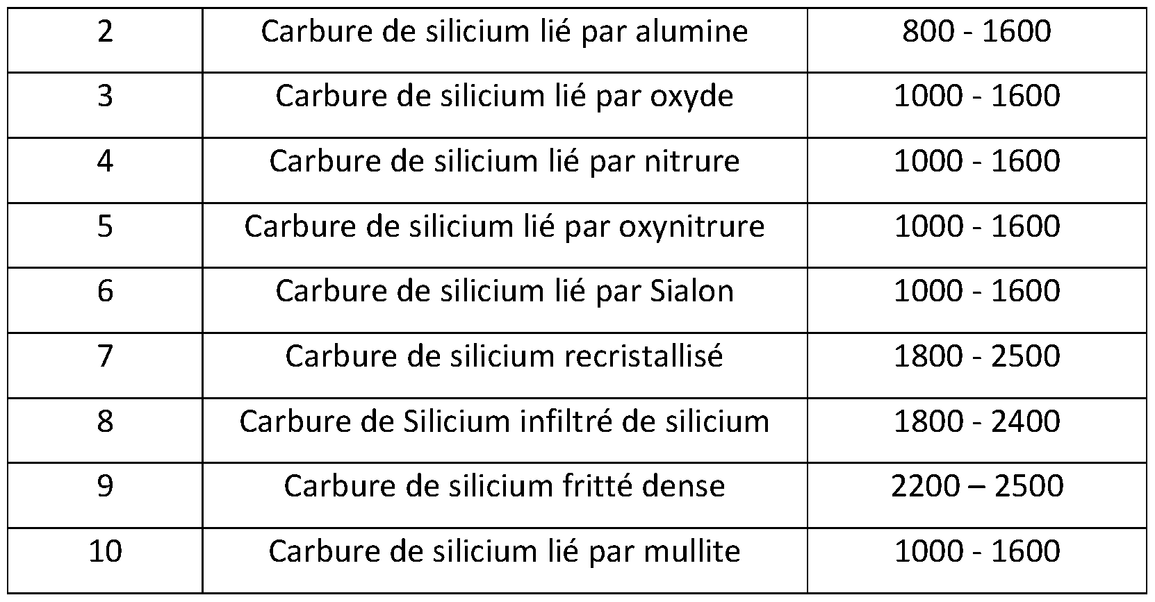
- Many bonding systems are used to sinter silicon carbide eg alumina, mullite, oxide, clay, nitride, oxynitride, SiAlON, bonding by SiC itself or "auto -lié ”(“ self-bonded ”in English), recrystallization, are some systems but the invention is not limited to them.
- the silicon carbide (SiC) grains are bonded by a SiC matrix or bonded together directly.
- the self-bonded silicon carbides are dense silicon carbide and recrystallized silicon carbide.
- Recrystallized silicon carbide is obtained by recrystallization via the evaporation and recondensation of a mixture of SiC raw material at a temperature above 2200 ° C in an inert atmosphere (usually argon) typically in induction furnaces. This process solidifies the microstructure of silicon carbide and results in a material called recrystallized silicon carbide.
- the SiC grains are mixed with silicates such as clay, mullite and the mixture is fired in a gas oven under an oxidizing atmosphere at a temperature typically up to 1400 ° C.
- Oxide-bonded silicon carbide is formed from a mixture of SiC particles and materials such as metal oxides, such as aluminum oxide and / or silicon oxide.
- Nitrogen bonded silicon carbide is obtained by firing mixtures of high purity silicon carbide, silicon or mineral additives in a nitrogenous atmosphere at high temperature (typically 1350 ° C to 1450 ° C). Silicon carbide may be bound by a silicon nitride phase (SÎ3N4) which forms during firing.
- the oxynitride bonded silicon carbide is formed from silicon carbide, silicon and mineral additives fired under a nitrogen atmosphere and optionally oxygen.
- Si Al ON usually described in the quaternary diagram SÎ3N4-A1N-A1203-SI02 are formed by reaction between different precursors such as silicon nitride (SÎ3N4), aluminum oxide (A1203) and aluminum nitride ( AIN). These precursors are initially present or intermediate components obtained during the reaction for the formation of the matrix binding the grains of silicon carbide.
- the advantage of using various varieties of sintered silicon carbide which exhibit a wide range of properties is that the appropriate material can be used for the various components of the vortex detector 112 depending on the design requirements of the device. each vortex.
- the interlocking elements (interlocking members) 1 16 are made of sintered silicon carbide.
- the majority of the interlocking elements comprise sintered silicon carbide.
- the majority means more than 50% by number, preferably more than 70% or at least more than 80% of the interlocking elements comprise sintered silicon carbide.
- the interlocking members 116 have a Z profile, but the invention is not limited to this particular profile. Any self-bonded or other material bonded silicon carbide can be used depending on the design requirements of the vortex detector.
- FIG. 4 illustrates an example of an interlocking member profile 116.
- the Z-shaped profile comprises a base 120 with two side flanges or flanges (“lateral flanges” in English) where a first flange 122 and a second flange 124 extend in a direction opposite to each other.
- the first flange 122 includes at least 2 or more other upwardly projecting teeth.
- the second flange 124 comprises at least 2 or even more other through openings (pass-through openings).
- the teeth of the first flange 122 of the Z-shaped interlocking members 116 of a row or ring 118 engage with the openings of the second flange 124 of an interlocking member (interlocking members) 116 Z-shaped from another row or ring 118 (not shown).
- the shapes shown are not limiting and can be adapted depending on the design of the vortex detector.
- the base 120 may be essentially flat and / or comprise a cross-shaped rib parallel to or along the diagonals of at least one of the faces of the base 120.
- FIG. 5 illustrates a flowchart relating to a method 500 of making a sintered silicon carbide material of the interlocking member 116 of the vortex detector 112 of a cyclone separator 100 in accordance with one embodiment of the present invention.
- Step 501 includes making a mixture of raw materials.
- Raw materials include silicon carbide alone or with other bonding materials depending on the required properties and particular functions.
- the bonding materials can be selected by clay, mullite, silicon or metal oxides, the metal oxides including in particular alumina and / or silica.
- the raw materials are weighed in a particular proportion and mixed using a mixer or a ball mill or a jar mixer.
- Step 502 includes shaping the mixture to make a body preformed or shaped by different processes such as pressing, vibro-pressing or various casting techniques.
- Step 503 includes drying the shaped body by air drying or in a low temperature oven.
- Step 504 includes firing the dried shaped body between 800 ° C and 2500 ° C, preferably between 1000 ° C and 2300 ° C, more preferably between 1200 ° C and 2000 ° C, in a sintering furnace under inert atmosphere, oxygen or nitrogen.
- the table below indicates the sintering temperatures of the different types of silicon carbide.
- the different types of sintered silicon carbide have a high thermal conductivity and a low coefficient of thermal expansion; therefore, it is very resistant to thermal shock and survives rapid thermal cycles compared to other materials.
- Abrasion resistance is generally associated with great hardness and great mechanical strength.
- the extreme hardness makes the sintered silicon carbide resistant to wear and erosion under conditions of mechanical abrasion.
- the terms “includes”, “includes”, “including”, “a”, “having” or any other variation of these terms, are intended to cover an inclusion not exclusive.
- a method, item or device that includes a list of features is not necessarily limited to those features but may include other features that are not expressly listed or inherent in that method, item, or device.
- “or” refers to an "or” inclusive and not to an “or” exclusive. For example, a condition A or B is satisfied by one of the following: A is true (or present) and B is false (or absent), A is false (or absent) and B is true (or present), and A and B are both true (or present).
Landscapes
- Cyclones (AREA)
Abstract
Description


Claims
Priority Applications (2)
| Application Number | Priority Date | Filing Date | Title |
|---|---|---|---|
| EP20746688.9A EP3976264A1 (fr) | 2019-05-31 | 2020-05-29 | Détecteur de vortex de préchauffeur à cyclone pour l'industrie cimentière à base de carbure de silicium fritté |
| BR112021022399A BR112021022399A2 (pt) | 2019-05-31 | 2020-05-29 | Detector de vórtice de preaquecedor de ciclone para a indústria de cimento à base de carbeto de silício sinterizado |
Applications Claiming Priority (2)
| Application Number | Priority Date | Filing Date | Title |
|---|---|---|---|
| IN201941021774 | 2019-05-31 | ||
| IN201941021774 | 2019-05-31 |
Publications (1)
| Publication Number | Publication Date |
|---|---|
| WO2020240102A1 true WO2020240102A1 (fr) | 2020-12-03 |
Family
ID=71833355
Family Applications (1)
| Application Number | Title | Priority Date | Filing Date |
|---|---|---|---|
| PCT/FR2020/000178 Ceased WO2020240102A1 (fr) | 2019-05-31 | 2020-05-29 | Detecteur de vortex de prechauffeur a cyclone pour l'industrie cimentiere a base de carbure de silicium fritte |
Country Status (3)
| Country | Link |
|---|---|
| EP (1) | EP3976264A1 (fr) |
| BR (1) | BR112021022399A2 (fr) |
| WO (1) | WO2020240102A1 (fr) |
Citations (4)
| Publication number | Priority date | Publication date | Assignee | Title |
|---|---|---|---|---|
| US4505051A (en) | 1982-08-03 | 1985-03-19 | Klockner-Humboldt-Deutz Ag | Cyclone heat exchanger including segmented immersion pipe |
| DE10033293A1 (de) * | 2000-05-12 | 2001-11-15 | Kloeckner Humboldt Wedag | Hitze- und verschleißbeanspruchtes Einbauelement, insbesondere Segment zum Zusammensetzen eines segmentierten Zyklontauchrohres |
| US20120204526A1 (en) * | 2011-02-14 | 2012-08-16 | Brownlee David A | Vortex finder for cyclone separator |
| WO2016102369A1 (fr) * | 2014-12-23 | 2016-06-30 | Khd Humboldt Wedag Gmbh | Tube plongeur pour cyclone dépoussiéreur |
-
2020
- 2020-05-29 WO PCT/FR2020/000178 patent/WO2020240102A1/fr not_active Ceased
- 2020-05-29 EP EP20746688.9A patent/EP3976264A1/fr not_active Withdrawn
- 2020-05-29 BR BR112021022399A patent/BR112021022399A2/pt not_active Application Discontinuation
Patent Citations (4)
| Publication number | Priority date | Publication date | Assignee | Title |
|---|---|---|---|---|
| US4505051A (en) | 1982-08-03 | 1985-03-19 | Klockner-Humboldt-Deutz Ag | Cyclone heat exchanger including segmented immersion pipe |
| DE10033293A1 (de) * | 2000-05-12 | 2001-11-15 | Kloeckner Humboldt Wedag | Hitze- und verschleißbeanspruchtes Einbauelement, insbesondere Segment zum Zusammensetzen eines segmentierten Zyklontauchrohres |
| US20120204526A1 (en) * | 2011-02-14 | 2012-08-16 | Brownlee David A | Vortex finder for cyclone separator |
| WO2016102369A1 (fr) * | 2014-12-23 | 2016-06-30 | Khd Humboldt Wedag Gmbh | Tube plongeur pour cyclone dépoussiéreur |
Also Published As
| Publication number | Publication date |
|---|---|
| BR112021022399A2 (pt) | 2021-12-28 |
| EP3976264A1 (fr) | 2022-04-06 |
Similar Documents
| Publication | Publication Date | Title |
|---|---|---|
| US8789626B2 (en) | Ultra hard/hard composite materials | |
| US20140287245A1 (en) | Dense composite material, method for manufacturing the same, joined body, and member for semiconductor manufacturing apparatuses | |
| US20170120339A1 (en) | New powder metal process for production of components for high temperature useage | |
| WO2005026076A1 (fr) | Materiau refractaire a base de sic comprenant du nitrure de silicium lie a celui-ci et procede de production correspondant | |
| US20120165179A1 (en) | Infiltrated silicon carbide bodies and methods of making | |
| KR20170095330A (ko) | 질소를 포함하는 SiC 막을 포함하는 여과기 | |
| TW202346204A (zh) | 氮化矽粉末及其製造方法、以及氮化矽燒結體及其製造方法 | |
| JP2017081816A (ja) | 焼結結合されたセラミック物品 | |
| EP3976264A1 (fr) | Détecteur de vortex de préchauffeur à cyclone pour l'industrie cimentière à base de carbure de silicium fritté | |
| DK2655705T3 (en) | crucibles | |
| FR3024049A1 (fr) | Dispositif de terminaison d'un reacteur d'une unite de craquage catalytique fluide | |
| KR20210097643A (ko) | 치밀질 복합 재료, 그 제법, 접합체 및 반도체 제조 장치용 부재 | |
| JP2007516349A (ja) | 優れた耐高温腐食性を有する先進的耐侵食性炭化物サーメット | |
| CN115045932A (zh) | 通风式制动盘的制备方法 | |
| WO2021023671A1 (fr) | Blindage en carbure de bore et en carbure de silicium | |
| US7544228B2 (en) | Large particle size and bimodal advanced erosion resistant oxide cermets | |
| US8262981B2 (en) | Ceramic material product and method of manufacture | |
| US7501090B2 (en) | Method for protecting metal surfaces utilizing erosion resistant oxide cermets | |
| US7247186B1 (en) | Advanced erosion resistant carbonitride cermets | |
| FR3024052A1 (fr) | Cyclone en materiau ceramique pour unite de craquage catalytique fluide | |
| US20240327301A1 (en) | Composite material sintered body, joined assembly, semiconductor manufacturing apparatus member, and composite material sintered body manufacturing method | |
| ZA200509372B (en) | Advanced erosion resistant oxide cermets | |
| JP2006199561A (ja) | セラミックス多孔体及びその製造方法 | |
| KR102947879B1 (ko) | 복합 재료 소결체, 접합체, 반도체 제조 장치용 부재, 및 복합 재료 소결체의 제조 방법 | |
| JP2004002130A (ja) | セラミックス多孔体及びその製造方法 |
Legal Events
| Date | Code | Title | Description |
|---|---|---|---|
| 121 | Ep: the epo has been informed by wipo that ep was designated in this application |
Ref document number: 20746688 Country of ref document: EP Kind code of ref document: A1 |
|
| REG | Reference to national code |
Ref country code: BR Ref legal event code: B01A Ref document number: 112021022399 Country of ref document: BR |
|
| NENP | Non-entry into the national phase |
Ref country code: DE |
|
| ENP | Entry into the national phase |
Ref document number: 112021022399 Country of ref document: BR Kind code of ref document: A2 Effective date: 20211108 |
|
| ENP | Entry into the national phase |
Ref document number: 2020746688 Country of ref document: EP Effective date: 20220103 |