WO2020240762A1 - 回転電機 - Google Patents
回転電機 Download PDFInfo
- Publication number
- WO2020240762A1 WO2020240762A1 PCT/JP2019/021468 JP2019021468W WO2020240762A1 WO 2020240762 A1 WO2020240762 A1 WO 2020240762A1 JP 2019021468 W JP2019021468 W JP 2019021468W WO 2020240762 A1 WO2020240762 A1 WO 2020240762A1
- Authority
- WO
- WIPO (PCT)
- Prior art keywords
- coil
- segment
- slot
- layer
- stator core
- Prior art date
- Legal status (The legal status is an assumption and is not a legal conclusion. Google has not performed a legal analysis and makes no representation as to the accuracy of the status listed.)
- Ceased
Links
Images







Classifications
-
- H—ELECTRICITY
- H02—GENERATION; CONVERSION OR DISTRIBUTION OF ELECTRIC POWER
- H02K—DYNAMO-ELECTRIC MACHINES
- H02K3/00—Details of windings
- H02K3/04—Windings characterised by the conductor shape, form or construction, e.g. with bar conductors
- H02K3/12—Windings characterised by the conductor shape, form or construction, e.g. with bar conductors arranged in slots
-
- H—ELECTRICITY
- H02—GENERATION; CONVERSION OR DISTRIBUTION OF ELECTRIC POWER
- H02K—DYNAMO-ELECTRIC MACHINES
- H02K3/00—Details of windings
- H02K3/04—Windings characterised by the conductor shape, form or construction, e.g. with bar conductors
- H02K3/24—Windings characterised by the conductor shape, form or construction, e.g. with bar conductors with channels or ducts for cooling medium between the conductors
-
- H—ELECTRICITY
- H02—GENERATION; CONVERSION OR DISTRIBUTION OF ELECTRIC POWER
- H02K—DYNAMO-ELECTRIC MACHINES
- H02K3/00—Details of windings
- H02K3/04—Windings characterised by the conductor shape, form or construction, e.g. with bar conductors
- H02K3/28—Layout of windings or of connections between windings
-
- H—ELECTRICITY
- H02—GENERATION; CONVERSION OR DISTRIBUTION OF ELECTRIC POWER
- H02K—DYNAMO-ELECTRIC MACHINES
- H02K3/00—Details of windings
- H02K3/46—Fastening of windings on the stator or rotor structure
- H02K3/52—Fastening salient pole windings or connections thereto
-
- H—ELECTRICITY
- H02—GENERATION; CONVERSION OR DISTRIBUTION OF ELECTRIC POWER
- H02K—DYNAMO-ELECTRIC MACHINES
- H02K15/00—Processes or apparatus specially adapted for manufacturing, assembling, maintaining or repairing of dynamo-electric machines
- H02K15/04—Processes or apparatus specially adapted for manufacturing, assembling, maintaining or repairing of dynamo-electric machines of windings prior to their mounting into the machines
- H02K15/0414—Processes or apparatus specially adapted for manufacturing, assembling, maintaining or repairing of dynamo-electric machines of windings prior to their mounting into the machines the windings consisting of separate elements, e.g. bars, segments or half coils
- H02K15/0421—Processes or apparatus specially adapted for manufacturing, assembling, maintaining or repairing of dynamo-electric machines of windings prior to their mounting into the machines the windings consisting of separate elements, e.g. bars, segments or half coils and consisting of single conductors, e.g. hairpins
-
- H—ELECTRICITY
- H02—GENERATION; CONVERSION OR DISTRIBUTION OF ELECTRIC POWER
- H02K—DYNAMO-ELECTRIC MACHINES
- H02K2213/00—Specific aspects, not otherwise provided for and not covered by codes H02K2201/00 - H02K2211/00
- H02K2213/03—Machines characterised by numerical values, ranges, mathematical expressions or similar information
Definitions
- the present invention relates to a rotary electric machine, and particularly relates to a rotary electric machine having a stator core having a plurality of slots and a stator having a plurality of segment coils housed in the slots of the stator core.
- the driving force is obtained by a rotary electric machine.
- the rotary electric machine includes a stator core having a plurality of slots and a plurality of copper cores housed in the slots of the stator core.
- a rotary electric machine having a stator with a segment coil of the above is used.
- a rotary electric machine provided with such a stator is described in, for example, Japanese Patent Application Laid-Open No. 2017-189020 (Patent Document 1).
- the rotary electric machine described in Patent Document 1 includes a stator core having a plurality of axially extending slots on the inner peripheral surface, and a copper segment coil inserted into the slots, and has a stator.
- a parallel portion substantially parallel to the end face portion of the stator core is formed at the top of the bent side (so-called turn portion) of the coil end of the segment coil protruding axially from the end face portion of the core.
- an intermediate inclined portion having an inclination formed by one predetermined angle is formed, and on the other intermediate inclined portion, two different predetermined angles are formed.
- An intermediate inclined portion having a stepped inclination is formed.
- segment coil having such a configuration, it is possible to provide a stator of a rotary electric machine in which the length of the coil end is suppressed while avoiding mechanical interference between adjacent coils at the bending side coil end of the segment coil. Is possible.
- the present invention aims to solve the above-mentioned problems in this type of rotary electric machine.
- an object of the present invention is to provide a novel rotary electric machine capable of suppressing an increase in the length of the coil end on the side where the turn portion is located and improving the cooling performance around the turn portion of the segment coil. is there.
- the feature of the present invention is The segment coil is fixed from one end face of the stator core, a first straight portion inserted into a specific slot, a second straight portion inserted into another specific slot different from the specific slot, and a stator core.
- Each slot has a turn portion extending outward in the axial direction of the child core and having a top connecting a first straight portion and a second straight portion, and each slot is radially from the inner peripheral side.
- the straight portions of the plurality of segment coils are inserted and arranged so as to be laminated on the outer peripheral side, and a bent portion is formed between each straight portion and the turn portion of the segment coils laminated in the radial direction. This bend is where the top of the turn is tilted towards the end face of the stator core.
- the turn portion extending from the end face portion of the stator core is bent outward in the radial direction, so that a sufficient gap is formed between the turn portions of the respective segment coils.
- the cooling performance can be improved by making it easier for the cooling medium to enter the gap or by increasing the substantial contact area between the coil and the cooling medium.
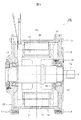
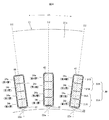
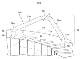
- FIG. 1 It is sectional drawing which shows the cross section in the axial direction of the rotary electric machine to which this invention is applied. It is a perspective view of the stator of the rotary electric machine shown in FIG. 1 seen from diagonally above. It is a front view which shows the shape of the segment coil shown in FIG. It is an enlarged cross-sectional view of a part of the end face part of the stator core which is the plane orthogonal to the axis of the stator core shown in FIG. It is explanatory drawing for demonstrating the arrangement state of each segment coil inserted into a slot. It is an enlarged perspective view explaining the relationship between the shape of the turn part of a segment coil and a slot.
- FIG. 1 is a cross-sectional view of a rotary electric machine 100 to which the present invention is applied.
- the rotary electric machine 100 of the present embodiment is mounted on an automobile such as an electric vehicle having no internal combustion engine or a hybrid vehicle having an internal combustion engine, and has a function as an electric motor for generating a driving force and generates power when the automobile is braked. It has a function as a generator to perform.
- the generated electric power is stored in a battery or the like mounted on the automobile.
- the rotary electric machine 100 mainly includes a rotor 10 and a stator 20.
- the rotor 10 and the stator 20 are housed in a storage space formed of an annular housing 14 having openings on both sides, a front cover 15 closing the openings on both sides of the housing 14, and a rear cover 16.
- the front cover 15 and the rear cover 16 are fixed to the housing 14 by bolts 17.
- the rotor 10 is fixed to, for example, a substantially cylindrical rotor core 11 formed by laminating a plurality of flat plate-shaped electromagnetic steel plates along the direction of the axis L, and inside the center of the rotor core 11.
- the drive shaft 12 is provided.
- the rotor core 11 has a plurality of magnet insertion holes provided at equal intervals in the circumferential direction and a plurality of magnets (neodymium) inserted and fixed in the magnet insertion holes. Magnets and ferrite magnets) are provided.
- the drive shaft 12 is rotatably supported by two bearings 13 located at both ends, and is integrally rotated with the rotor core 11 around the axis L of the rotor core 11.
- the bearing 13 is arranged inside the front cover 15 and the rear cover 16.
- the bearing 13 on the side of the front cover 15 is supported by the retainer 18, and the retainer 18 is fixed to the front cover 15 by bolts 19.
- the drive shaft 12 applies a rotational force to the drive wheels (not shown) via a reduction mechanism (not shown), and also applies a rotational force from the drive wheels.
- the stator 20 is wound around, for example, a substantially annular-shaped stator core 21 formed by laminating a plurality of flat-plate-shaped electromagnetic steel sheets along the direction of the axis L, and the stator core 21. It is provided with a coil 30.
- the rotor core 11 is rotatably arranged with a minute gap in the radial direction D2 of the stator core 21, and the axis L of the stator core 21 and the axis of the rotor core 11 are rotatably arranged. It matches with L. Since the rotary electric machine having these configurations is a well-known configuration, further description thereof will be omitted.
- FIG. 2 is a view of the stator 20 of the rotary electric machine 100 shown in FIG. 1 taken out and viewed from diagonally above.
- a plurality of slit-shaped slots 22 are provided on the inner circumference of the annular stator core 21 at equal intervals in the circumferential direction D1 and extend radially outward in the radial direction D2. See).
- the slot 22 penetrates from one end face portion 21a to the other end face portion 21b along the direction of the axis L of the stator core 21 when viewed in the direction of the axis L of the stator core 21.
- the inner peripheral surface of the stator core 21 has an opening (slit) 22a continuous from one end surface portion 21a to the other end surface portion 21b along the direction of the axis L.
- stator core 21 for example, 48 slots 22 are formed at equal angles in the circumferential direction D1, and coils 30 are arranged in each slot 22. In this way, the slots 22 are formed radially on the stator core 21 with the axis L as the center.
- the coil 30 of the stator 20 has a first coil group 30A arranged on the inner peripheral side in the radial direction D2 of the stator core 21 and an outer peripheral side of the first coil group 30A. It is composed of a second coil group 30B arranged in.
- the first coil group 30A and the second coil group 30B are an aggregate of copper segment coils 31A and 31B.
- One coil end 35A, 35B of the coil 30 constitutes a first coil group 30A and a second coil group 30B in the direction of the axis L of the stator core 21, and the turn portions 33 of the segment coils 31A and 31B (FIG. 3). See). Further, the other coil ends 36A and 36B of the coil 30 are composed of a connecting portion 32 for connecting predetermined segment coils 31A and 31B having the same phase.
- the turn portion 33 is a bending side coil end 35A, 35B
- the connecting portion 32 is a connecting side coil end 36A, 36B
- the slot insertion portion 34 (see FIG. 3) is in between.
- the slot insertion portion 34 may be referred to as a straight portion 34.
- connection side coil ends 36A and 36B adjacent to each coil group are connected to each other by TIG welding by a connecting portion 32 for sequentially connecting the segment coils 31A and 31B. That is, the connecting portions 32 of the adjacent segment coils 31A of the first coil group 30A are sequentially connected, and the connecting portions 32 of the adjacent segment coils 31B of the second coil group 30B are sequentially connected. Since these configurations are also well known, further description will be omitted.
- the turn of the segment coil 31 constituting the coil 30 is performed.
- the shape of the portion 33 is important.
- FIG. 3 shows the shapes of the segment coils 31A and 31B. Since the segment coils 31A and 31B are formed in substantially the same shape, the configurations of the segment coils 31A and 31B will be described together. However, the segment coils 31A and 31B are characterized by a turn portion 33 that is bent outward in the radial direction when inserted into the slot 22, and this will be described in detail with reference to FIG.
- the segment coil 31 includes a pair of straight portions 34a and 34r arranged in the slot 22, and a turn portion 33 is formed so as to connect one side of the pair of straight portions 34a and 34r. Further, the other side of the pair of straight portions 34a and 34r is opened to form the connecting portions 32a and 32r. As a result, the bending side coil end 35 and the connecting side coil end 36 are formed.
- the turn portion 33 has a top 33c formed near the center, and the top 33c has segment coils 31 (plural) incorporated in the stator core 21 when the segment coil 31 is incorporated in the stator core 21.
- the top portions 33c are arranged so as to be in a positional relationship parallel to the core end face portion 21a.
- the turn portion 33 has a “mountain-shaped” shape from the viewpoint of the radial direction with the segment coil 31 arranged in the slot 22.
- the connecting portion 33aa between the intermediate inclined portion 33ba and the straight portion 34a and the connecting portion 33ar between the intermediate inclined portion 33br and the straight portion 34r have a bent shape, whereby the intermediate inclined portion 33ba and the top portion 33c, A pair of straight lines 34a and 34r are connected via the intermediate inclined portion 33br. Therefore, the segment coil 31 is formed in a substantially "U" shape from the pair of straight portions 34a and 34r and the turn portion 33 bent so as to connect the pair of straight portions 34a and 34r. ..
- the straight line portion on the front side in the clockwise rotation direction is set as the straight line portion 34a, and the clockwise rotation direction.
- the straight portion on the rear side is the straight portion 34r.
- the linear portions 34a and 34r of the segment coils 31A and 31B forming the first coil group 30A and the second coil group 30B are arranged in a form in which they are laminated in the radial direction.
- the laminated state is as shown in FIG. 4, which will be described with reference to FIG.
- the straight line portion 34r is arranged in an odd number layer, and the straight line portion 34a is arranged in an even number layer.
- the layer located on the innermost peripheral side of the slot 22 is the first layer, and the second layer, the third layer, and the fourth layer are formed toward the outer peripheral side.
- the coils 30 include a first coil group 30A arranged on the inner peripheral side in the radial direction D2 and a second coil group 30B arranged on the outer peripheral side of the first coil group 30A. have.
- the first coil group 30A and the second coil group 30B have two coil groups, but as in Patent Document 1, three or more coil groups are provided. Needless to say, it's okay.
- the coil 30 is composed of segment coils 31A and 31B having a rectangular wire having a rectangular cross-sectional shape from the viewpoint of suppressing a decrease in the space factor.
- segment coils 31A and 31B made of flat wire are used.
- an insulator 40 made of insulating paper or the like is arranged on the inner peripheral wall surface of each slot 22, and the segment coils 31A forming the first coil group 30A and the second coil group 30B, It covers the circumference of 31B.
- the pair of linear portions 34a and 34r of the segment coils 31A and 31B are inserted and arranged in the slot 22 extending in the direction of the axis L of the stator core 21 so as to be laminated in the radial direction D2.
- the part 34r is the first layer.
- the straight portion 34a of the second segment coil 31A constituting the first coil group 30A which is located outside the straight portion 34r of the first layer located on the innermost peripheral side, is a stator with respect to the first layer. It is a second layer adjacent to the outside of the radial D2 of the core 21.
- the first segment coil 31A and the second segment coil 31A are segment coils having the same shape, and the linear portions 34r and 34a of the respective segment coils 31A are separated by a predetermined pitch to form a stator core. It is arranged in a plurality of slots 22 arranged in a ring shape in 21, and a set of these slots constitutes a first coil group 30A.
- the straight portion located outside the second layer when viewed in the radial direction D2 of the stator core 21. 34r is the third layer.
- the linear portion 34a of the fourth segment coil 31B constituting the second coil group 30B is a fourth layer adjacent to the outer side of the stator core 21 in the radial direction D2 with respect to the third layer.
- the third segment coil 31B and the fourth segment coil 31B are also segment coils having the same shape, and the linear portions 34r and 34a of the respective segment coils 31B are separated by a predetermined pitch to form a stator core. It is arranged in a plurality of slots 22 arranged in a ring shape in 21, and a second coil group 30B is formed by a set thereof.
- the length (line length) of the turn portion 33 is formed longer than that of the segment coil 31A arranged on the inner peripheral side.
- the straight portion 34r of the segment coils 31A and 31B is arranged in the odd-numbered layer, and the straight portion 34a of the segment coils 31A and 31B is arranged in the even-numbered layer.
- the pair of linear portions 34a and 34r of the respective segment coils 31A and 31B are arranged in different slots 22 separated by a predetermined pitch interval in the circumferential direction D1 of the stator core 21.
- FIG. 5 shows the arrangement relationship of the segment coils 31A and 31B when the slot 22 is viewed from the inside to the outside in the radial direction.
- the segment coil 31A of the first coil group 30A is shown by omitting the display of the segment coil 31B of the second coil group 39B. Further, in the slot 22 (region R) on the right side, the segment coil 31B of the second coil group 30B is shown in which the display of the segment coil 31A of the first coil group 30A is omitted.
- the straight portion 34r of the first segment coil 31A forming the first layer As shown in the region (L), the straight portion 34r of the first segment coil 31A forming the first layer, which is located on the innermost peripheral side of the slot 22, has an intermediate inclined portion 33br diagonally upward to the right in the drawing. It extends toward the slot 22 after the next predetermined pitch via.
- the straight portion 34a of the second segment coil 31A forming the second layer adjacent to the outer peripheral side in the radial direction of the first layer has a predetermined pitch via the intermediate inclined portion 33ba on the diagonally lower side in the drawing. It extends from the previous slot 22.
- the straight portion 34r of the third segment coil 31B forming the third layer located on the outer peripheral side of the second layer of the slot 22 is obliquely upward to the right when viewed in the drawing. It extends toward the slot 22 after the next predetermined pitch via the intermediate inclined portion 33br.
- the straight portion 34a of the fourth segment coil 31B forming the fourth layer adjacent to the outer peripheral side in the radial direction of the third layer is obliquely downward in the drawing via the intermediate inclined portion 33ba and before a predetermined pitch. It extends from slot 22 of.
- the odd-numbered straight line portion 34r laminated in the slot 22 faces the slot 22 after the next predetermined pitch via the intermediate inclined portion 33br on the diagonally upper right side in the drawing.
- the straight portion 34a of the even-numbered layer extends diagonally downward from the slot 22 before a predetermined pitch via the intermediate inclined portion 33ba as seen in the drawing.
- FIG. 6 shows the configuration of the turn portion 33 in a state where one segment coil 31 shown in FIG. 4 is inserted into the slot 22.
- the segment coil 31B of the second coil group 30B is shown, and as described above, the cross section of the segment coil 31B is formed in a rectangular shape in order to increase the space factor.
- the segment coil 31B constituting the second coil group 30B includes a turn portion 33 protruding from the slot 22 in the direction of the axis L of the stator core 21, and a pair of straight portions 34a and 34r penetrating the two predetermined slots 22. It is configured to have.
- the rotary electric machine 100 of the present embodiment is characterized by the shape of the turn portion 33 of the segment coil 31 wound around the slot 22 of the stator core 21.
- the open end side of the pair of straight portions 34a and 34r of the segment coil 31B penetrates the slot 22 in the direction of the axis L of the stator core 21 from the end face portion 21b on the opposite side of the end face portion 21a of the stator core 21. It projects outward along the direction of the axis L.
- the open end protruding in the direction of the axis L from the end face portion 21b of the stator core 21 on the opposite side of the turn portion 33 becomes the connection side coil end 36 and is sequentially connected by the connection portion 32 as shown in FIG. ..
- the turn portion 33 of the segment coil 31B is the top portion 33c formed of a “one side” that is farthest from the end face portion 21a of the stator core 21 and substantially parallel to the end face portion 21a when viewed in the direction of the axis L. have.
- the turn portion 33 is connected to both ends of the top portion 33c and has a pair of intermediate inclined portions 33ba and 33br extending downward in the drawing so as to approach the end surface portion 21a of the stator core 21. There is.
- the intermediate inclined portions 33ba and 33br are connected to the pair of straight portions 34a and 34r via the connecting portions 33aa and 33ar, respectively.
- the other straight line portion 34a is the second layer.
- the other straight line portion 34a is the fourth layer.
- the intermediate inclined portion 33br, the top portion 33c, and the intermediate inclined portion 33ba from one straight portion 34r (odd layer) to the other straight portion 34a (even layer) are orthogonal to the end face portion 21a of the stator core 21. Seen from the viewpoint, it is inclined by one layer from the inner peripheral side to the outer peripheral side.
- the turn portion 33 is curved in a "mountain shape" shape having the top 33c as the apex as a whole. Then, the top portions 33c and the intermediate inclined portions 33ba and 33br forming the turn portion 33 are located outside the pair of straight portions 34a and 33r in the radial direction D2 of the stator core 21 so that the bent portions 37a, It has an inclined shape that is bent outward in the radial direction starting from 37r and in a direction approaching the end face portion 21a.
- the apex 33c and the pair of intermediate inclined portions 33ba and 33br constituting the turn portion 33 are inclined so as to expand outward in the radial direction as they approach the apex 33c, starting from the bent portions 37a and 37r. Has and is bent.
- the segment coils 31A and 31B are preformed into the above-mentioned shape before being inserted into the slot 22.
- the top portion 33c and the pair of intermediate inclined portions 33ba and 33br constituting the turn portion 33 have the diameter of the stator core 21 when viewed from a viewpoint orthogonal to the end face portion 21a of the stator core 21 as described above. In the direction D2, it is inclined by one layer from the inner peripheral side to the outer peripheral side. Further, in addition to this, with respect to the axis L, the top portions 33c and the intermediate inclined portions 33ba and 33br move outward in the radial direction from the axis L and approach the end face portion 21a, starting from the bent portions 37a and 37r. It is tilted to do.
- FIG. 7 shows a state in which the second coil group 30B is removed in order to make it easier to understand the shape of the segment coil 31 constituting the coil 30.
- the pair of linear portions 34a and 34r of the individual segment coils 31A of the first coil group 30A are arranged in a pair of slots 22 separated by a predetermined pitch interval in the circumferential direction D1 of the stator core 21. Will be done.
- the pair of linear portions 34a and 34r of the respective segment coils 31A are arranged in the pair of slots 22 separated by 6 pitch intervals.
- one straight portion 34r is arranged on the innermost side of the stator core 21 in the radial direction D2 with respect to the other straight portion 34a (see FIG. 4). ..
- the pair of linear portions 34a and 34r of the respective segment coils 31 of the first coil group 30A are arranged in the pair of slots 22 separated by a predetermined pitch interval in the circumferential direction D1 of the stator core 21.
- 48 segment coils 31A are sequentially arranged in 48 slots 22 of the stator core 21.
- the first coil group 30A is composed of a plurality of segment coils 31A.
- the second coil group 30B has the same configuration.
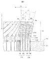
- FIG. 8 shows an enlarged part of the first coil group 30A and the second coil group 30B constituting the coil 30 shown in FIG. In some slots 22, the display of the segment coil 31B of the fourth layer located on the outermost peripheral side is omitted.
- the turn portion 33 of the segment coil 31A constituting the first coil group 30A arranged on the inner peripheral side of the slot 22 the first coil group in the radial direction D2 of the stator core 21.
- a turn portion 33 of the segment coil 31B constituting the second coil group 30B is arranged outside the 30A.
- the segment coils 31A and 31B are inclined so as to expand outward in the radial direction D2 starting from the bent portions 37a and 37r.
- the coil 30 wound around the stator 20 is composed of the first coil group 30A and the second coil group 30B, and is wound around the slot 22 of the stator core 21 by "distributed winding of wave winding". ing. Needless to say, as described above, it may have three or more coil groups.
- the segment coils 31A and 31B are arranged in the same slot 22 in the arrangement form shown in FIG. Then, the straight line portion 34r (first layer) of the first segment coil 31A of the first coil group 30A is arranged from the inner peripheral side toward the outside in the radial direction, and the straight line portion 34r (first layer) of the first segment coil 31A of the first coil group 30A is arranged on the outer side. Part 34a (second layer) is arranged.
- a straight portion 34r (third layer) of the third segment coil 31B of the second coil group 30B is arranged outside the straight portion 34a (second layer) of the second segment coil 31A, and a third layer is arranged outside the straight portion 34r (third layer) of the third segment coil 31B.
- the straight line portion 34a (fourth layer) of the segment coil 31B of No. 4 is arranged.
- the intermediate inclined portion 33br connected to the straight portion 34r of the first layer and the third layer with the paper surface as a boundary extends so as to project toward the front side of the paper surface, and conversely, the second layer and the fourth layer
- the intermediate inclined portion 33ba connected to the straight portion 34a has a form extending from the back side of the paper surface so as to be connected to the straight portion 34a of the slot 22.
- the bent portion of the straight portion 34r arranged in the odd-numbered layer is the bent portion 37rA
- the bent portion of the straight portion 34a arranged in the even-numbered layer is bent.
- the bent portion 37aA in the segment coil 31B constituting the second coil group 30B, the bent portion of the straight portion 34r arranged in the odd-numbered layer is the bent portion 37rB
- the bent portion of the straight portion 34a arranged in the even layer is the bent portion 34a. Is described as a bent portion 37aB.
- the turn portion 33 forming the bending side coil end 35 starts from the bending portions 37aA, 37rA, portions 37aB, 37rB with the straight portions 34a, 34r of the laminated segment coils 31 as the starting points, and the axis L It has an inclined shape that is bent outward in the radial direction D2 of the stator core 21 with respect to the direction of.
- the top portion 33c constituting the turn portion 33 and the pair of intermediate inclined portions 33ba and 33br are inclined in a direction gradually moving outward from the axis L starting from the bent portions 37aA and 37rA and the portions 37aB and 37rB. In this case, the top 33c is farthest from the axis L.
- the straight portion 34r of the first segment coil 31A constituting the first layer of the first coil group 30A arranged on the innermost peripheral side of the radial direction D2 of the slot 22 is bent.
- the shape is such that the portion 37rA is not formed. That is, the straight line portion 34r extends substantially parallel to the axis L and is connected to the intermediate inclined portion 33br.
- a bent portion 37rA may be formed on the straight portion 34r of the first segment coil 31A constituting the first layer of the first coil group 30A.
- the inclination angle ⁇ of the bent portions 37aA, 37rB, 37aB of the straight portions 34a, 34r of the segment coils 31A, 31B laminated along the radial direction D2 is the straight line of the segment coils 31A, 31B.
- the portions 34a and 34r are set so large that they are located on the outer peripheral side of the slot 22 in the radial direction D2.
- the inclination angle ⁇ means the angle formed by the line segment from the bent portions 37aA, 37rB, and 37aB to the top 33c of the turn portion 33 and the axis L of the stator core 21.
- the inclination angle ⁇ 1 of the bent portion 37aA of the second layer, the inclination angle ⁇ 2 of the bent portion 37rB of the third layer, and the inclination angle ⁇ 3 of the bent portion 37aB of the fourth layer are “ ⁇ 1 ⁇ 2 ⁇ 3”.
- the inclination angle ⁇ is not limited to this, and an appropriate angle may be selected.
- angle difference ⁇ between the respective inclination angles ⁇ 1, ⁇ 2, and ⁇ 3 is set to be equal to “2.5 °”, but it goes without saying that they may be set to unequal angles. .. It is also possible to set the angle difference ⁇ to be larger toward the outside, or to set the angle difference ⁇ to be larger toward the inside.
- the bent portion 37aA of the straight portion 34a of the second layer, the bent portion 37rB of the straight portion 34r of the third layer, and the bent portion 37aB of the straight portion 34a of the fourth layer are located on the outer peripheral side of the radial direction D2 of the slot 22.
- the top portion 33c is also formed so that the turn portion 33 located on the outer peripheral side of the slit 22 in the radial direction D2 is closer to the end surface portion 21a of the stator core 21 when viewed in the direction of the axis L.
- FIG. 10 is a view of the first coil group 30A and the second coil group 30B shown in FIG. 8 from different viewpoints.
- the two segment coils 31A and 31B that are adjacent to each other in the circumferential direction D1 of the stator core 21 are located between the two tops 33c that are adjacent to each other in the circumferential direction D1 of the stator core 21. It is shown that they face each other with a gap G in the radial direction D2.
- the gap G allows the cooling medium to smoothly flow into the turn portion 33, and the coil 30 can be efficiently cooled.
- the rotary electric machine 100 of the present embodiment includes a stator core 21, a plurality of slots 22 provided in the stator core 21, and segment coils 31A and 31B arranged in the slots 22. ing.
- the segment coils 31A and 31B have a pair of straight line portions 34a and 34r arranged in different slots 22 and a turn portion 33 connecting the pair of straight line portions 34a and 34r. ..
- the turn portion 33 has a pair of intermediate inclined portions 33ba and 33br connected to the straight portions 34a and 34r.
- bent portions 37a and 37r are provided between the straight portions 34a and 34r and the turn portion 33, and the inclination angle ⁇ of the bent portions 37a and 37r becomes larger as it is located on the outer peripheral side of the radial direction D2 of the slot 22. It is set.
- the inclination angle ⁇ 1 of the bent portion 37aA formed in the straight portion 34a of the second layer the inclination angle ⁇ 2 of the bent portion 37rB formed in the straight portion 34r of the third layer, and the straight portion 34a of the fourth layer. It has a relationship of “ ⁇ 1 ⁇ 2 ⁇ 3” with the inclination angle ⁇ 3 of the bent portion 37aB formed in.
- the bent portions 37a and 37r are bent so that the turn portion 33 is inclined in the direction away from the axis L so that the segment coils 31A and 31B are located on the outer peripheral side in the radial direction D2 of the slot 22. That is, as the segment coil 31 is located on the outer peripheral side in the radial direction D2 of the slot 22, the top portion 33c and the intermediate inclined portions 33ba and 33br are closer to the end face portion 21a of the stator core 21 when viewed in the direction of the axis L. It is folded into.
- a sufficient gap is formed in the turn portions 33 adjacent to each other in the circumferential direction D1 of the stator core 21 to avoid mechanical interference, and the cooling medium can easily enter the gap, or the coil and the cooling are cooled.
- the cooling performance can be improved by increasing the substantial contact area of the medium.
- the two tops 33c adjacent to each other in the circumferential direction D1 face each other with a gap G in the radial direction D2.
- the cooling medium easily enters the gap G, or the contact area of the coil 30 with the cooling medium becomes large, so that the cooling effect can be enhanced.
- the segment coils 31A and 31B that are adjacent to each other in the circumferential direction D1 of the stator core 21 are located between the two tops 33c that are adjacent to each other in the circumferential direction D1 of the stator core 21. They face each other with a gap G in the radial direction D2.
- the cooling performance is improved by avoiding the interference of the turn portions 33 of the bending side coil ends 35A and 35B without increasing the length of the coil end 35. Can be made to.
- the inclination angle ⁇ 1 of the bent portion 37aA formed in the straight portion 34a of the second layer the inclination angle ⁇ 2 of the bent portion 37rB formed in the straight portion 34r of the third layer, and the straight line of the fourth layer.
- the inclination angle ⁇ 3 of the bent portion 37aB formed in the portion 34a has a relationship of “ ⁇ 1 ⁇ 2 ⁇ 3”.
- the inclination angle ⁇ 1 of the bent portion 37aA formed in the straight portion 34a of the second layer and the inclination angle ⁇ 2 of the bent portion 37rB formed in the straight portion 34r of the third layer are
- the turn portion 33 is configured to be inclined outward in the radial direction, so that the space where the segment coils 31A and 31B exist is large. Can be taken.
- the two tops 33c adjacent to each other in the circumferential direction D1 face each other with a gap G in the radial direction D2.
- the cooling medium easily enters the gap G, or the contact area of the coil 30 with the cooling medium becomes large, so that the cooling effect can be enhanced.
- the two tops 33c adjacent to each other in the circumferential direction D1 face each other with a gap G in the radial direction D2 of the stator core 21.
- the line length of the turn portion 33 of the segment coil 31A located on the inner peripheral side and the line length of the turn portion 33 of the segment coil 31B located on the outer peripheral side are on the outer peripheral side having a long radius.
- the segment coil 31B located is longer. Therefore, the coil resistance increases by this amount, and the amount of heat generated also increases. If only one segment coil 31B is used, the effect is not as great as on the left, but since a plurality of segment coils 31B, for example, n segment coils 31B are connected in series, the coil resistance becomes n times and can be ignored. There is a risk that it will disappear.
- the bent portion of the straight portion 34r arranged in the odd-numbered layer is changed to the bent portion 37rA and the even-numbered layer.
- the bent portion of the linear portion 34a to be arranged is the bent portion 37aA
- the bent portion of the straight portion 34r arranged in the odd-numbered layer is arranged in the bent portion 37rB and the even-numbered layer in the segment coil 31B constituting the second coil group 30B.
- the forming positions of the bent portion 37aA of the straight portion 34a of the second layer, the bent portion 37rB of the straight portion 34r of the third layer, and the bent portion 37aB of the straight portion 34a of the fourth layer are The closer to the outer peripheral side of the slot 22 in the radial direction D2, the closer it is to the end face portion 21a of the stator core 21 when viewed in the direction of the axis L.
- the relationship between the length "S2" to the end face portion 21a of the coil 21 and the length "S3" from the bending point of the bending portion 37aB of the straight portion 34a of the fourth layer to the end face portion 21a of the stator coil 21 is "S3". It has a relationship of ⁇ S2 ⁇ S1 ".
- the length from the bent portions 37aB and 37rB of the segment coil 31B located on the outer peripheral side to the end face portion 21a of the stator coil 21 is shortened.
- the wire length of the turn portion 33 of the segment coil 31B located on the outer peripheral side can be shortened, the increase in coil resistance can be suppressed, and the amount of heat generated can also be suppressed.
- the bent portions 37rA, 37aA, 37rB, and 37aB are formed so that the lengths of the turn portion 33 of the segment coil 31A on the inner peripheral side and the segment coil 31B on the outer peripheral side are set to substantially the same length. The position is fixed.
- the segment coil has a first straight line portion inserted into a specific slot and a second straight line portion inserted into another specific slot different from the specific slot.
- a turn portion having a top extending from one end face portion of the stator core toward the outside in the axial direction of the stator core and connecting the first straight portion and the second straight portion, respectively.
- the linear portions of the plurality of segment coils are inserted and arranged so as to be laminated from the inner peripheral side to the outer peripheral side in the radial direction, and the linear portions of the segment coils laminated in the radial direction are inserted and arranged.
- a bent portion is formed between the turn portions, and the bent portion inclines the top of the turn portion toward the end face of the stator core.
- the present invention is not limited to the above-described embodiment, and includes various modifications.
- the above-described embodiment has been described in detail in order to explain the present invention in an easy-to-understand manner, and is not necessarily limited to the one including all the described configurations.
- it is possible to replace a part of the configuration of one embodiment with the configuration of another embodiment and it is also possible to add the configuration of another embodiment to the configuration of one embodiment.
Landscapes
- Engineering & Computer Science (AREA)
- Power Engineering (AREA)
- Windings For Motors And Generators (AREA)
Abstract
Description
セグメントコイルが、特定のスロットに挿入される第1の直線部と、特定のスロットとは異なる他の特定のスロットに挿入される第2の直線部と、固定子コアの一方の端面部から固定子コアの軸線方向の外側に向けて延び、第1の直線部、及び第2の直線部とを接続する頂部を有するターン部とを備え、夫々のスロットには、径方向に内周側から外周側に積層されるように複数のセグメントコイルの夫々の直線部が挿入、配置されると共に、径方向に積層されたセグメントコイルの夫々の直線部とターン部の間に屈曲部が形成され、この屈曲部がターン部の頂部を固定子コアの端面に近づく方向に傾斜させている、ところにある。
Claims (10)
- 複数のスロットを有する固定子コアと、前記固定子コアの前記スロットの夫々に収納される複数のセグメントコイルとを備えた固定子を有する回転電機であって、
前記セグメントコイルは、特定の前記スロットに挿入される第1の直線部と、特定の前記スロットとは異なる他の特定の前記スロットに挿入される第2の直線部と、前記固定子コアの一方の端面部から前記固定子コアの軸線方向の外側に向けて延び、前記第1の直線部、及び前記第2の直線部とを接続するように折り曲げられた頂部を有するターン部とを備え、
夫々の前記スロットには、径方向に内周側から外周側に積層されるように複数の前記セグメントコイルの夫々の前記直線部が挿入、配置されると共に、
径方向に積層された前記セグメントコイルの夫々の前記直線部と前記ターン部の間に屈曲部が形成され、前記屈曲部は前記ターン部の前記頂部が前記固定子コアの端面に近づく方向に前記ターン部を傾斜させている
ことを特徴とする回転電機。 - 請求項1に記載の回転電機であって、
前記セグメントコイルの夫々の前記ターン部は、前記スロットの外周側に位置する前記セグメントコイルほど大きく傾斜されている
ことを特徴とする回転電機。 - 請求項1に記載の回転電機であって、
前記セグメントコイルの夫々の前記ターン部は、前記スロットの前記セグメントコイルの位置に関係なく等しく傾斜されていることを特徴とする回転電機。 - 請求項2或いは請求項3に記載の回転電機であって、
複数の前記セグメントコイルは、少なくとも、前記固定子コアの内周側に配置された第1コイル群、及び前記第1コイル群の外周側に配置された第2コイル群を形成し、
前記第1コイル群の前記セグメントコイルの前記ターン部の線長と、前記第2コイル群の前記セグメントコイルの前記ターン部の線長とが略同一に決められている
ことを特徴とする回転電機。 - 請求項4に記載の回転電機であって、
前記ターン部が傾斜する起点となる前記屈曲部の位置は、前記スロットの外周側に位置する前記セグメントコイルほど前記固定子コアの前記端面部に近づくように設定されている
ことを特徴とする回転電機。 - 請求項2或いは請求項3に記載の回転電機であって、
複数の前記セグメントコイルは、少なくとも、前記固定子コアの内周側に配置された第1コイル群、及び前記第1コイル群の外周側に配置された第2コイル群を形成し、
前記セグメントコイルの前記ターン部には、前記第1の直線部と前記第2の直線部を繋ぐ中間傾斜部の間に前記頂部が形成され、
前記第1コイル群と前記第2コイル群を形成する前記セグメントコイルの相互に隣接する2つの前記ターン部は、隣接する2つの前記頂部の間で前記固定子コアの径方向に間隙を有して対向されている
ことを特徴とする回転電機。 - 複数のスロットを有する固定子コアと、前記固定子コアの前記スロットの夫々に収納される複数のセグメントコイルとを備えた固定子を有する回転電機であって、
前記セグメントコイルは、特定の第1のスロットに挿入される第1の直線部と、特定の前記第1のスロットとは異なる特定の第2のスロットに挿入される第2の直線部と、
記第1の直線部、及び前記第2の直線部とを接続するように折り曲げられた頂部を有するターン部とを備え、
複数の前記セグメントコイルは、少なくとも、前記固定子コアの内周側に配置された第1コイル群、及び前記第1コイル群の外周側に配置された第2コイル群を形成し、
前記第1のスロット、及び前記第2のスロットにおいて、前記第1コイル群を形成する前記セグメントコイルの前記第1の直線部は、前記第1のスロット、及び前記第2のスロットの最も内周側に第1層として配置され、前記第1コイル群を形成する前記セグメントコイルの前記第2の直線部は、前記第1のスロット、及び前記第2のスロットの前記第1層の外周側に第2層として配置され、
前記第1のスロット、及び前記第2のスロットにおいて、前記第2コイル群を形成する前記セグメントコイルの前記第1の直線部は、前記第1のスロット、及び前記第2のスロットの前記第2層の外周側に第3層として配置され、前記第2コイル群を形成する前記セグメントコイルの前記第2の直線部は、前記第1のスロット、及び前記第2のスロットの前記第3層の外周側に第4層として配置され、
前記第2層から前記第4層までの前記直線部から延びる前記ターン部との間には屈曲部が形成され、前記屈曲部は、前記屈曲部を起点として前記頂部に至る線分が径方向で外側に向かって前記固定子コアの軸線から遠ざかる方向に傾斜するように折り曲げられている
ことを特徴とする回転電機。 - 請求項7に記載の回転電機であって、
前記屈曲部を起点として前記ターン部の前記頂部に至る線分と、前記固定子コアの軸線とのなす角度を傾斜角θとした時、
前記第2層の前記頂部に至る線分は傾斜角θ1で傾斜され、前記第3層の前記頂部に至る線分は傾斜角θ2で傾斜され、前記第4層の前記頂部に至る線分は傾斜角θ3で傾斜されると共に、
夫々の前記傾斜角θ1、θ2、θ3は、θ1<θ2<θ3の関係を有している
ことを特徴とする回転電機。 - 請求項7に記載の回転電機であって、
前記屈曲部を起点として前記ターン部の前記頂部に至る線分と、前記固定子コアの軸線とのなす角度を傾斜角θとした時、
前記第2層の前記頂部に至る線分は傾斜角θ1で傾斜され、前記第3層の前記頂部に至る線分は傾斜角θ2で傾斜され、前記第4層の前記頂部に至る線分は傾斜角θ3で傾斜されると共に、
夫々の前記傾斜角θ1、θ2、θ3は、θ1=θ2=θ3の関係を有している
ことを特徴とする回転電機。 - 請求項8或いは請求項9に記載の回転電機であって、
前記ターン部が傾斜する起点となる夫々の前記屈曲部の位置は、前記スロットの外周側に位置する前記セグメントコイルほど前記固定子コアの端面部に近づくように決められている
ことを特徴とする回転電機。
Priority Applications (5)
| Application Number | Priority Date | Filing Date | Title |
|---|---|---|---|
| US17/605,727 US12021423B2 (en) | 2019-05-30 | 2019-05-30 | Dynamo-electrical machine |
| EP19930552.5A EP3979468A4 (en) | 2019-05-30 | 2019-05-30 | DYNAMO-ELECTRIC MACHINE |
| JP2021521679A JP7361106B2 (ja) | 2019-05-30 | 2019-05-30 | 回転電機 |
| CN201980096286.9A CN113812066B (zh) | 2019-05-30 | 2019-05-30 | 旋转电机 |
| PCT/JP2019/021468 WO2020240762A1 (ja) | 2019-05-30 | 2019-05-30 | 回転電機 |
Applications Claiming Priority (1)
| Application Number | Priority Date | Filing Date | Title |
|---|---|---|---|
| PCT/JP2019/021468 WO2020240762A1 (ja) | 2019-05-30 | 2019-05-30 | 回転電機 |
Publications (1)
| Publication Number | Publication Date |
|---|---|
| WO2020240762A1 true WO2020240762A1 (ja) | 2020-12-03 |
Family
ID=73552791
Family Applications (1)
| Application Number | Title | Priority Date | Filing Date |
|---|---|---|---|
| PCT/JP2019/021468 Ceased WO2020240762A1 (ja) | 2019-05-30 | 2019-05-30 | 回転電機 |
Country Status (5)
| Country | Link |
|---|---|
| US (1) | US12021423B2 (ja) |
| EP (1) | EP3979468A4 (ja) |
| JP (1) | JP7361106B2 (ja) |
| CN (1) | CN113812066B (ja) |
| WO (1) | WO2020240762A1 (ja) |
Cited By (2)
| Publication number | Priority date | Publication date | Assignee | Title |
|---|---|---|---|---|
| JP2022128408A (ja) * | 2021-02-22 | 2022-09-01 | ドクター エンジニール ハー ツェー エフ ポルシェ アクチエンゲゼルシャフト | 電動機の固定子及び電動機 |
| US11990807B2 (en) | 2021-10-04 | 2024-05-21 | Mitsubishi Electric Corporation | Electric rotating machine |
Families Citing this family (2)
| Publication number | Priority date | Publication date | Assignee | Title |
|---|---|---|---|---|
| JP7570266B2 (ja) * | 2021-03-29 | 2024-10-21 | 株式会社日立製作所 | 回転電機の固定子、回転電機、電気駆動システム、及び電動ホイール |
| JP7776983B2 (ja) * | 2021-12-27 | 2025-11-27 | 株式会社Subaru | ステータおよびその製造方法 |
Citations (5)
| Publication number | Priority date | Publication date | Assignee | Title |
|---|---|---|---|---|
| JP2004088993A (ja) * | 2002-06-26 | 2004-03-18 | Denso Corp | 車両用交流発電機 |
| WO2009084473A1 (ja) * | 2007-12-27 | 2009-07-09 | Aisin Aw Co., Ltd. | ステータ及びこれを用いた回転電機 |
| JP2014197968A (ja) * | 2013-03-29 | 2014-10-16 | 株式会社デンソー | 回転電機 |
| JP2017189020A (ja) | 2016-04-06 | 2017-10-12 | 日立オートモティブシステムズ株式会社 | 回転電機の固定子、及びこれを備えた回転電機 |
| JP2018026964A (ja) * | 2016-08-10 | 2018-02-15 | 富士電機株式会社 | 固定子及びそれを備えた回転電機 |
Family Cites Families (10)
| Publication number | Priority date | Publication date | Assignee | Title |
|---|---|---|---|---|
| JP3734166B2 (ja) | 2002-06-25 | 2006-01-11 | 株式会社デンソー | 回転電機のセグメント順次接合ステータコイルおよびその製造方法 |
| JP3786059B2 (ja) * | 2002-06-25 | 2006-06-14 | 株式会社デンソー | 回転電機のセグメント順次接合ステータコイルおよびその製造方法 |
| US6794785B2 (en) * | 2002-06-26 | 2004-09-21 | Denso Corporation | Alternator for vehicles |
| JP4007186B2 (ja) * | 2002-12-20 | 2007-11-14 | 株式会社デンソー | 回転電機の固定子 |
| JP5070248B2 (ja) * | 2009-06-30 | 2012-11-07 | 日立オートモティブシステムズ株式会社 | 回転電機とその製造方法 |
| JP5363403B2 (ja) * | 2010-04-19 | 2013-12-11 | トヨタ自動車株式会社 | モータ |
| JP5712660B2 (ja) * | 2011-02-18 | 2015-05-07 | トヨタ自動車株式会社 | ステータ製造方法 |
| JP2013121296A (ja) * | 2011-12-08 | 2013-06-17 | Toyota Motor Corp | 固定子、固定子の製造方法、及びその製造装置 |
| JP6022896B2 (ja) * | 2012-10-29 | 2016-11-09 | 日立オートモティブシステムズ株式会社 | 回転電機 |
| JP6667634B2 (ja) * | 2016-06-30 | 2020-03-18 | 日立オートモティブシステムズ株式会社 | 回転電機 |
-
2019
- 2019-05-30 WO PCT/JP2019/021468 patent/WO2020240762A1/ja not_active Ceased
- 2019-05-30 EP EP19930552.5A patent/EP3979468A4/en active Pending
- 2019-05-30 CN CN201980096286.9A patent/CN113812066B/zh active Active
- 2019-05-30 US US17/605,727 patent/US12021423B2/en active Active
- 2019-05-30 JP JP2021521679A patent/JP7361106B2/ja active Active
Patent Citations (5)
| Publication number | Priority date | Publication date | Assignee | Title |
|---|---|---|---|---|
| JP2004088993A (ja) * | 2002-06-26 | 2004-03-18 | Denso Corp | 車両用交流発電機 |
| WO2009084473A1 (ja) * | 2007-12-27 | 2009-07-09 | Aisin Aw Co., Ltd. | ステータ及びこれを用いた回転電機 |
| JP2014197968A (ja) * | 2013-03-29 | 2014-10-16 | 株式会社デンソー | 回転電機 |
| JP2017189020A (ja) | 2016-04-06 | 2017-10-12 | 日立オートモティブシステムズ株式会社 | 回転電機の固定子、及びこれを備えた回転電機 |
| JP2018026964A (ja) * | 2016-08-10 | 2018-02-15 | 富士電機株式会社 | 固定子及びそれを備えた回転電機 |
Non-Patent Citations (1)
| Title |
|---|
| See also references of EP3979468A4 |
Cited By (2)
| Publication number | Priority date | Publication date | Assignee | Title |
|---|---|---|---|---|
| JP2022128408A (ja) * | 2021-02-22 | 2022-09-01 | ドクター エンジニール ハー ツェー エフ ポルシェ アクチエンゲゼルシャフト | 電動機の固定子及び電動機 |
| US11990807B2 (en) | 2021-10-04 | 2024-05-21 | Mitsubishi Electric Corporation | Electric rotating machine |
Also Published As
| Publication number | Publication date |
|---|---|
| US20220181938A1 (en) | 2022-06-09 |
| CN113812066A (zh) | 2021-12-17 |
| EP3979468A1 (en) | 2022-04-06 |
| US12021423B2 (en) | 2024-06-25 |
| EP3979468A4 (en) | 2023-01-04 |
| JP7361106B2 (ja) | 2023-10-13 |
| JPWO2020240762A1 (ja) | 2020-12-03 |
| CN113812066B (zh) | 2025-01-14 |
Similar Documents
| Publication | Publication Date | Title |
|---|---|---|
| US11309760B2 (en) | Rotary electric machine | |
| JP7361106B2 (ja) | 回転電機 | |
| CN106416000B (zh) | 定子以及旋转机械 | |
| JP4886624B2 (ja) | 永久磁石式回転電機、及び永久磁石式回転電機システム | |
| JP5554383B2 (ja) | 回転電機の固定子、及びその固定子の製造方法 | |
| JP5480879B2 (ja) | 回転電機の固定子および回転電機 | |
| JP6461158B2 (ja) | 回転電機の固定子、及びこれを備えた回転電機 | |
| JP2012222922A (ja) | 回転電機の固定子 | |
| CN105706339B (zh) | 定子及具备该定子的旋转电机 | |
| US20210376671A1 (en) | Manufacturing method of stator for vehicle rotary electric machine | |
| CN104716765A (zh) | 旋转电机 | |
| JP7785948B2 (ja) | ステータ巻線用ステータスロットを有し、ステータスロットの少なくとも1つに冷却流体が流れることができる電気機械用ステータ | |
| JP6667634B2 (ja) | 回転電機 | |
| US20250202295A1 (en) | Stator for an electric machine | |
| JP5163278B2 (ja) | 回転電機の固定子 | |
| JP2019213245A (ja) | 回転電機のロータ、その製造方法および回転電機 | |
| JP2019533422A (ja) | 電気機械のためのスリーブおよびシャフト | |
| JP4936117B2 (ja) | モータ | |
| CN111478519A (zh) | 旋转电机 | |
| JPWO2017158700A1 (ja) | 回転電機、回転電機の製造方法 | |
| JP5105143B2 (ja) | モータ | |
| JP7306040B2 (ja) | モータ | |
| JP5256835B2 (ja) | 回転電機の固定子及び回転電機 | |
| JP2018170814A (ja) | 回転電機の固定子及びそれを用いた回転電機 | |
| JP2015211563A (ja) | 回転電機のステータ、及びこれを備えた回転電機 |
Legal Events
| Date | Code | Title | Description |
|---|---|---|---|
| 121 | Ep: the epo has been informed by wipo that ep was designated in this application |
Ref document number: 19930552 Country of ref document: EP Kind code of ref document: A1 |
|
| ENP | Entry into the national phase |
Ref document number: 2021521679 Country of ref document: JP Kind code of ref document: A |
|
| NENP | Non-entry into the national phase |
Ref country code: DE |
|
| ENP | Entry into the national phase |
Ref document number: 2019930552 Country of ref document: EP Effective date: 20220103 |
|
| WWG | Wipo information: grant in national office |
Ref document number: 201980096286.9 Country of ref document: CN |