WO2020240973A1 - Imprimante - Google Patents
Imprimante Download PDFInfo
- Publication number
- WO2020240973A1 WO2020240973A1 PCT/JP2020/009841 JP2020009841W WO2020240973A1 WO 2020240973 A1 WO2020240973 A1 WO 2020240973A1 JP 2020009841 W JP2020009841 W JP 2020009841W WO 2020240973 A1 WO2020240973 A1 WO 2020240973A1
- Authority
- WO
- WIPO (PCT)
- Prior art keywords
- paper
- roll paper
- sensor
- printer
- roll
- Prior art date
- Legal status (The legal status is an assumption and is not a legal conclusion. Google has not performed a legal analysis and makes no representation as to the accuracy of the status listed.)
- Ceased
Links
Images





Classifications
-
- B—PERFORMING OPERATIONS; TRANSPORTING
- B41—PRINTING; LINING MACHINES; TYPEWRITERS; STAMPS
- B41J—TYPEWRITERS; SELECTIVE PRINTING MECHANISMS, i.e. MECHANISMS PRINTING OTHERWISE THAN FROM A FORME; CORRECTION OF TYPOGRAPHICAL ERRORS
- B41J15/00—Devices or arrangements of selective printing mechanisms, e.g. ink-jet printers or thermal printers, specially adapted for supporting or handling copy material in continuous form, e.g. webs
- B41J15/04—Supporting, feeding, or guiding devices; Mountings for web rolls or spindles
-
- B—PERFORMING OPERATIONS; TRANSPORTING
- B65—CONVEYING; PACKING; STORING; HANDLING THIN OR FILAMENTARY MATERIAL
- B65H—HANDLING THIN OR FILAMENTARY MATERIAL, e.g. SHEETS, WEBS, CABLES
- B65H16/00—Unwinding, paying-out webs
- B65H16/02—Supporting web roll
-
- B—PERFORMING OPERATIONS; TRANSPORTING
- B65—CONVEYING; PACKING; STORING; HANDLING THIN OR FILAMENTARY MATERIAL
- B65H—HANDLING THIN OR FILAMENTARY MATERIAL, e.g. SHEETS, WEBS, CABLES
- B65H23/00—Registering, tensioning, smoothing or guiding webs
- B65H23/02—Registering, tensioning, smoothing or guiding webs transversely
- B65H23/032—Controlling transverse register of web
-
- B—PERFORMING OPERATIONS; TRANSPORTING
- B65—CONVEYING; PACKING; STORING; HANDLING THIN OR FILAMENTARY MATERIAL
- B65H—HANDLING THIN OR FILAMENTARY MATERIAL, e.g. SHEETS, WEBS, CABLES
- B65H26/00—Warning or safety devices, e.g. automatic fault detectors, stop-motions, for web-advancing mechanisms
- B65H26/08—Warning or safety devices, e.g. automatic fault detectors, stop-motions, for web-advancing mechanisms responsive to a predetermined diameter
-
- B—PERFORMING OPERATIONS; TRANSPORTING
- B65—CONVEYING; PACKING; STORING; HANDLING THIN OR FILAMENTARY MATERIAL
- B65H—HANDLING THIN OR FILAMENTARY MATERIAL, e.g. SHEETS, WEBS, CABLES
- B65H43/00—Use of control, checking, or safety devices, e.g. automatic devices comprising an element for sensing a variable
- B65H43/02—Use of control, checking, or safety devices, e.g. automatic devices comprising an element for sensing a variable detecting, or responding to, absence of articles
Definitions
- the present invention relates to a printer.
- Patent Document 1 Japanese Patent Application Laid-Open No. 2006-232474 (hereinafter, also referred to as Patent Document 1) describes a printer provided with a pressing means for pressing a side portion of a roll paper toward a reference surface.
- Patent Document 2 Japanese Patent Application Laid-Open No. 55-16875 (hereinafter, also referred to as Patent Document 2), the lateral pressure point of the leaf spring that laterally presses the roll paper in the axial direction is arranged on the pulling side of the roll paper from the center of the roll paper.
- Patent Document 3 describes a printer provided with a pair of guide plates for pressing the front half of the side surface of the roll paper.
- the printers described in Patent Documents 1 to 3 can prevent skewing of the roll paper by pushing the side surface of the roll paper with various pressing members.
- a near-end sensor (hereinafter, also simply referred to as a sensor) that detects that the remaining amount of paper has decreased are known.
- Patent Document 4 Japanese Patent Application Laid-Open No. 2017-109335 (hereinafter, also referred to as Patent Document 4) describes a sensor that detects that the roll portion of the printing medium has moved to a predetermined area of the storage portion, and an angle with respect to the side surface of the roll portion.
- a printer is described that has a holding portion having a pair of side walls that press the side surfaces of the roll portion from both sides.
- the printer described in Patent Document 4 has the same configuration in which the roll paper is placed at a position where the sensor is arranged even when the direction of gravity applied to the roll paper stored in the print medium storage portion changes by approximately 90 °. Can be moved.
- An object of the present invention is to provide a printer capable of preventing the occurrence of skewing of roll paper regardless of the remaining amount of paper and improving the detection accuracy of a sensor that detects the remaining amount of paper.
- the printer according to the present invention has a storage unit for storing roll paper in which printing paper is rolled into a roll, a printing unit for printing on the paper, and a roll paper stored in the storage unit for transporting the paper to the printing unit.
- a transport section a push member having a push surface facing the end face of the roll paper stored in the storage section, a sensor for detecting that the remaining amount of paper wound around the roll paper has decreased to a predetermined amount, and a sensor.
- the storage unit stores the roll paper so that the center position of the roll paper moves as the amount of paper decreases, and the push-in surface until the sensor detects that the remaining amount of paper has decreased to a predetermined amount.
- the pressing surface is curved.
- the pressing member further has an inclined surface extending obliquely from the end of the pressing surface in the direction opposite to the end surface of the roll paper.
- the printer according to the present invention is an urging member that urges the surface of the pressing member facing the end surface of the roll paper from the surface opposite to the surface of the pressing member facing the end surface of the roll paper. It is preferable to have more.
- the printer according to the present invention further has a partition plate on which a pressing member and a sensor are mounted and arranged so as to be movable according to the width of the roll paper.
- the pressing member has a central portion, a first arm portion extending upward from the central portion, and a second arm portion extending downward from the central portion.
- the printer according to the present invention can prevent the occurrence of skewing of the roll paper regardless of the remaining amount of paper, and can improve the detection accuracy of the sensor that detects the remaining amount of paper.
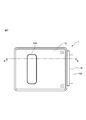
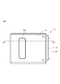
- FIG. 1 It is a perspective view (the 1) of the printer which concerns on 1st Embodiment. It is a perspective view (the 2) of the printer which concerns on 1st Embodiment. It is a top view of the printer shown in FIG. (A) is a partially enlarged perspective view (No. 1) of the printer shown in FIG. 1, and (b) is a partially enlarged perspective view (No. 2) of the printer shown in FIG. (A) is a plan view of the partition plate shown in FIG. 1, and (b) is a rear view of the partition plate shown in FIG. 1 showing a state in which the rear case of the partition plate 24 is removed. It is an exploded perspective view of the partition plate shown in FIG.
- FIG. 1 is a diagram (No. 1) for explaining the movement of roll paper due to a decrease in the remaining amount of paper in the printer shown in FIG. 1, and (a) is a diagram in which the remaining amount of paper is reduced to a predetermined amount detected by a near-end sensor.
- FIG. 3B is a cross-sectional view of a main part of the printer along the line BB shown in FIG. 3, and FIG. 3B is shown in FIG. 3 after the remaining amount of paper has decreased to a predetermined amount detected by the near-end sensor.
- -It is sectional drawing of the main part of the printer along line B.
- FIG. 2 is a diagram (No.
- FIG. 2 2) for explaining the movement of the roll paper due to the decrease in the remaining amount of paper in the printer shown in FIG. 1, and (a) shows that the remaining amount of paper has decreased to a predetermined amount detected by the near-end sensor.
- FIG. 3B is taken along line BB shown in FIG. 3 after the remaining amount of paper has decreased to a predetermined amount detected by the near-end sensor.
- FIG. 5 is a cross-sectional view of a main part of the printer along the line DD shown in FIG. 11 for explaining the movement of the roll paper with the decrease in the remaining amount of paper in the printer shown in FIG.
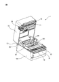
- FIG. 1 is a perspective view when the upper case of the printer is opened when the roll paper is not stored in the printer
- FIG. 2 is a perspective view when the upper case of the printer is opened when the roll paper is stored in the printer. It is a figure.
- the printer 1 includes a storage unit 10, a thermal head 11, a platen roller 12, a fixed blade 13, a movable blade 14, an upper case 15, a lower case 16, a rotating shaft 17, an open / close button 18, and paper. It has a discharge port 19.
- the printer 1 is a thermal printer of a drop-in method or the like that prints characters or figures by bringing a heated thermal head 11 into contact with a roll paper 100 that is a thermal paper that changes color by heating. In the roll paper 100, the printing paper 103 is wound around a cylindrical core material in a roll shape.
- the storage portion 10 has a roll paper holder 20, a first roll paper roller 21, a second roll paper roller 22, a reference surface 23, a partition plate 24, a first guide shaft 25, and a second guide shaft. 26 and 26 are arranged, and the roll paper 100 in which the printing paper 103 is wound in a roll shape is stored.
- Each of the roll paper holder 20, the first roll paper roller 21, the second roll paper roller 22, the reference surface 23, the partition plate 24, the first guide shaft 25, and the second guide shaft 26 is arranged inside the lower case 16. To.
- the roll paper holder 20 is tilted so that the center position of the roll paper 100 moves as the amount of paper 103 decreases, and the rolls stored in the storage unit 10 together with the first roll paper roller 21 and the second roll paper roller 22. Holds the paper 100.
- the first roll paper roller 21 and the second roll paper roller 22 rotate along with the transport of the roll paper 100 while supporting the roll paper 100 together with the roll paper holder 20.
- the second roll paper roller 22 is a protrusion located between the near-end sensor 45 and the thermal head 11 and in contact with the side surface of the roll paper 100.
- the reference surface 23 is arranged so as to face one end surface 102 of the roll paper 100 stored in the storage unit 10.
- the partition plate 24 is arranged so as to face the reference surface 23 and move in the direction of the reference surface 23 according to the width of the roll paper 100, and when the roll paper 100 is stored in the storage portion 10, the other side of the roll paper 100 Facing the end face 101 of.
- the first guide shaft 25 and the second guide shaft 26 are stretched in parallel with the stretching direction of the second roll paper roller 22 and movably support the partition plate 24 in the direction orthogonal to the reference surface 23.
- the thermal head 11 is a printing unit that is arranged at a position facing the platen roller 12 when the upper case 15 is closed and prints characters or figures on the paper 103 wound around the roll paper 100.
- the paper 103 is sandwiched between the thermal head 11 and the platen roller 12 for printing.
- the thermal head 11 is pressed in the direction of the platen roller 12 by the built-in spring material, and at the same time, heats the built-in heating element according to the print data indicating the characters or figures to be printed, and prints the characters or figures on the paper 103. To do.
- the platen roller 12 is a transport unit that is rotated by a drive motor (not shown) to transport the paper 103 from the roll paper 100 stored in the storage unit 10 to the thermal head 11.
- the paper 103 sandwiched between the thermal head 11 and the platen roller 12 is conveyed by the rotation of the platen roller 12.
- the paper 103 is cut by the fixed blade 13 and the movable blade 14 at the rear end of the area to be printed, and is discharged from the paper ejection port 19.
- the fixed blade 13 is fixedly arranged between the thermal head 11 and the end face of the upper case 15 on the paper discharge port 19 side, and the movable blade 14 is formed between the platen roller 12 and the end face of the lower case 16 on the paper discharge port 19 side. It is arranged so that it can be moved vertically between them.
- the paper 103 is cut by the fixed blade 13 and the movable blade 14, and is ejected from the printer 1 in the direction indicated by the arrow A in FIG.
- the upper case 15 covers the upper part of the lower case 16 and is rotatably supported by the rotating shaft 17 on the upper part of the lower case 16.
- the upper case 15 has a window portion 150 formed on the surface thereof.
- the open / close button 18 is arranged in the upper case 15, and when pressed, the upper case 15 rotates upward with respect to the lower case 16 about the rotation shaft 17, and the upper case 15 opens.
- the printer 1 is used with the upper case 15 closed.
- the partition plate 24 will be described in detail with reference to FIGS. 5 and 6.
- the partition plate 24 includes a front case 41, a rear case 42, a pushing member 43, an urging member 44, a near-end sensor 45 which is also simply called a sensor, a sensor cover 46, an operating member 47, and a support plate 48. And a fastening member 49.
- the front case 41 and the rear case 42 are base materials on which the pushing member 43, the urging member 44, the near-end sensor 45, the sensor cover 46, the operating member 47, the support plate 48, and the fastening member 49 are mounted.
- the front case 41 has a facing surface 410, a first guide shaft support portion 411, a second guide shaft support portion 412, a fixing portion 413, and a first inner surface 414 opposite to the facing surface. Further, the front case 41 is formed with a first opening 415, a second opening 416, and a first shaft hole 417 penetrating from the facing surface 410 to the first inner surface 414, and the pushing member accommodating portion is formed on the facing surface 410. 418 is formed.
- the facing surface 410 faces the reference surface 23 and faces the end surface 101 of the roll paper 100 when the roll paper 100 is stored in the storage portion 10. Further, on the facing surface 410, the near-end sensor 45 is movably arranged so as to face the end surface 101 of the roll paper 100 via the first opening 415. Further, in the facing surface 410, the operating member 47 is movably arranged via the second opening 416. On the facing surface 410, a sensor position display 419 indicating the position of the near-end sensor 45 is arranged in the vicinity of the operating member 47. The sensor position display 419 displays two numbers, a number "1" indicating the first position and a number "2" indicating the second position. The first position and the second position are determined according to the diameter of the core material around which the roll paper 100 is wound. The first position and the second position may be selected by the user of the printer 1 according to the intended use and preference.
- the first guide shaft 25 penetrates the first guide shaft support portion 411, and the second guide shaft 26 penetrates the second guide shaft support portion 412.
- the fixing portion 413 is fixed to the roll paper holder 20 by engaging with the engaging portion formed on the roll paper holder 20.
- the distance between the partition plate 24 and the reference surface 23 via the first guide shaft 25 and the second guide shaft 26 can be changed according to the width of the roll paper 100, and the position coincides with the width of the roll paper 100. Is fixed by the fixing portion 413.
- the first inner surface 414 is the opposite surface of the facing surface 410, and a corrugated portion 420 having a corrugated shape is formed.
- the corrugated portion 420 corresponds to the numbers "1" and "2" displayed on the sensor position display 419 for the near-end sensor 45 moved by the operating member 47 by engaging with the arm portion 483 of the support plate 48. It is fixed in the first position and the second position.
- the rear case 42 has a second inner surface 421.
- the second inner surface 421 is formed so that a plurality of convex portions 422 are formed along the outer edge, and the second shaft hole 423 penetrates from the second inner surface 421 to the back surface at a position corresponding to the first shaft hole 417.
- the plurality of convex portions 422 engage with the concave portions formed on the outer edge of the first inner surface 414 of the front case 41 to integrate the front case 41 and the rear case 42.
- the rear case 42 has a shape corresponding to the shape of the support plate 48 around the second shaft hole 423, and a recess 424 for accommodating the support plate 48 is formed.
- the pushing member 43 includes a central portion 430, a first arm portion 431, a second arm portion 432, a shaft portion 433, a first engaging portion 434, a second engaging portion 435, and an inclined surface 436.
- the central portion 430 has a substantially circular planar shape.
- the first arm portion 431 extends linearly upward in the vertical direction so as to be separated from the central portion 430 from the outer edge of the central portion 430.
- the second arm portion 432 extends linearly from the outer edge of the central portion 430 in a direction opposite to the extending direction of the first arm portion 431, that is, downward in the vertical direction so as to be separated from the central portion 430.
- the distance between the ends of the first arm portion 431 and the second arm portion 432 and the center of the central portion 430 is substantially the same as the distance between the near-end sensor 45 and the operating member 47 and the center of the central portion 430.
- the surfaces of the central portion 430, the first arm portion 431, and the second arm portion 432 are pushing surfaces for pushing the end surface 101 of the roll paper 100.
- the shaft portion 433 stands linearly from the back surface of the central portion 430.
- the first engaging portion 434 is arranged at the tip of the first arm portion 431, and the second engaging portion 435 is arranged at the tip of the second arm portion 432.
- the first engaging portion 434 and the second engaging portion 435 fix the pushing member 43 to the front case 41 by engaging with the engaging portion formed inside the pushing member accommodating portion 418.
- the inclined surface 436 extends diagonally from the end of the pushing surface, which is the surface of the central portion 430, the first arm portion 431, and the second arm portion 432, in the direction opposite to the reference surface 23.
- the inclined surface 436 extends from both ends of the central portion 430, extends from both ends and the upper end of the first arm portion 431, and extends from both ends and the lower ends of the second arm portion 432.
- the urging member 44 is a spring that engages with the shaft portion 433 of the pushing member 43, specifically, the shaft portion 433 of the pushing member 43 penetrates the inside, and one end of the first shaft hole 417 of the front case 41. It is arranged so as to be in contact with the receiving portion formed along the inner wall and the other end to be in contact with the back surface of the central portion 430 of the pushing member 43. By pressing the urging member 44 from the back surface of the central portion 430, any portion of the central portion 430, the first arm portion 431, and the second arm portion 432 of the pushing member 43 is linearly aligned with the end surface 101 of the roll paper 100. The roll paper 100 is pushed in the direction of the reference surface in contact with each other.
- the pushing member 43 is urged from the back surface by the urging member 44.
- the pushing surface of the pushing member 43 facing the end face 101 of the roll paper 100 is projected in the vertical direction toward the end face 101 of the roll paper 100. It is curved.
- the pushing surface of the pushing member 43 is convexly curved in the vertical direction toward the end face 101 of the roll paper 100, so that the pushing surface of the pushing member 43 comes into contact with the end face 101 of the roll paper 100 by a linear portion extending in the horizontal direction.
- the near-end sensor 45 is, for example, an optical sensor, which detects that the remaining amount of the paper 103 wound around the roll paper 100 has decreased to a predetermined amount. Since the configuration and function of the near-end sensor 45 are well known, detailed description thereof will be omitted here.
- the sensor cover 46 is arranged on the back surface of the near-end sensor 45, and fixes the near-end sensor 45 to the support plate 48.
- the surface of the operating member 47 is fixed to the support plate 48 so that the surface can be seen from the facing surface 410 via the second opening 416, and when an operator (not shown) operates the position of the near-end sensor 45, the operator Manipulated by.
- the support plate 48 has a support surface 480, a sensor fixing portion 481, an operating member fixing portion 482, and an arm portion 483, and is rotatable in a plane orthogonal to the moving direction of the partition plate 24.
- the support plate 48 is formed so that the through hole 484 penetrates from the support surface 480 to the back surface of the support surface 480 at a position corresponding to each of the first shaft hole 417 and the second shaft hole 423.
- the shaft portion 433 of the pushing member 43 is inserted into the through hole 484 together with the first shaft hole 417 and the second shaft hole 423.
- the support plate 48 has a boss formed around the through hole 484 with the center of the shaft portion 433 as the center point in response to the operation member 47 fixed to the operation member fixing portion 482 being operated by the operator. Rotate as. By rotating the support plate 48, the near-end sensor 45 fixed to the sensor fixing portion 481 rotates about the shaft portion 433 around the boss formed around the through hole 484.
- the fastening member 49 is screwed with the shaft portion 433 of the pushing member 43 to fix the pushing member 43 to the front case 41.
- the fastening member 49 functions as a stopper that prevents the pushing member 43 from bending more than a certain amount and prevents the pushing member 43 from coming off from the front case 41.
- FIG. 8 shows the movement of the roll paper 100 as the remaining amount of the paper 103 decreases when the near-end sensor 45 is placed in the first position
- FIG. 9 shows the paper when the near-end sensor 45 is placed in the second position.
- the movement of the roll paper 100 with the decrease of the remaining amount of 103 is shown.
- 8 (a) and 9 (a) are cross-sectional views of a main part of the printer 1 along the line BB shown in FIG. 3 when the remaining amount of the paper 103 is reduced to a predetermined amount detected by the near-end sensor 45.
- Is. 8 (b) and 9 (b) are cross-sectional views of a main part of the printer 1 along the line BB shown in FIG. 3 after the remaining amount of the paper 103 is reduced to a predetermined amount detected by the near-end sensor 45. Is.
- the near-end sensor 45 is adjusted to two positions according to the diameter of the core material around which the roll paper is wound.
- the first position indicated by the number “1” in the sensor position display 419 is a position where the near-end sensor 45 is arranged when the diameter of the core material around which the paper 103 is wound is relatively small.
- the second position indicated by the number “2" in the sensor position display 419 is a position where the near-end sensor 45 is arranged when the diameter of the core material around which the paper 103 is wound is relatively large.
- the first position and the second position may be selected by the user of the printer 1 according to the intended use and preference.
- the roll paper 100 wound around the core material 104 is formed in the recesses indicated by arrows C in FIGS. 8 (a) and 8 (b) and 9 (a) and 9 (b) as the remaining amount of the paper 103 decreases. Move to the fitting position.
- the roll paper 100 is located between the push-in surface of the near-end sensor 45 and the push-in member 43 and the thermal head 11, and is a protrusion on which the end face 101 of the roll paper 100 comes into contact with the second roll paper roller 22 and the roll paper holder. Move while being supported by 20. As the roll paper 100 moves while being supported by the second roll paper roller 22 and the roll paper holder 20, the near-end sensor 45 and the pushing surface of the pushing member 43 are sequentially separated from the end face 101 of the roll paper 100.
- the near-end sensor 45 detects that the remaining amount of the paper 103 of the roll paper 100 has decreased to a predetermined amount.
- the pushing member 43 contacts the end face 101 of the opposing roll paper 100 until the near-end sensor 45 detects that the remaining amount of the paper 103 has decreased to a predetermined amount.
- the pushing member 43 is separated from the end face 101 of the roll paper 100 after the near-end sensor 45 detects that the remaining amount of the paper 103 has decreased to a predetermined amount. ..
- the pushing force is not applied to the roll paper 100 from the pushing member 43.
- the printer 2 is different from the printer 1 in that the partition plate 34 is arranged in the storage unit 10 instead of the partition plate 24. Since the configurations and functions of the components of the printer 2 other than the partition plate 34 are the same as the configurations and functions of the components of the printer 1 with the same reference numerals, detailed description thereof will be omitted here.
- the partition plate 34 will be described in detail with reference to FIGS. 13 and 14.
- the partition plate 34 differs from the partition plate 24 in that the front case 51 is provided in place of the front case 41.
- the front case 51 differs from the front case 41 in that the first opening 515, the second opening 516, and the corrugated portion 520 are formed in place of the first opening 415, the second opening 416, and the corrugated portion 420. ..
- the front case 51 is different from the front case 41 in that the sensor position display 519 is arranged instead of the sensor position display 419.
- the components of the partition plate 34 other than the first opening 515, the second opening 516, the sensor position display 519, and the corrugated portion 520 are the components and functions of the partition plate 24 having the same reference numerals. Since it is the same as the above, detailed description thereof will be omitted here.
- the first opening 515 and the second opening 516 are through holes penetrating from the facing surface 410 to the first inner surface 414, and the length in the longitudinal direction is longer than that of the first opening 415 and the second opening 416, respectively. long.
- the near-end sensor 45 is movably arranged in the first opening 515 so as to face the end surface 101 of the roll paper 100, and the operating member 47 is movably arranged in the second opening 416.
- the sensor position display 519 is arranged in the vicinity of the operating member 47 and indicates the position of the near-end sensor 45.
- the sensor position display 519 displays five numbers from the number "1" indicating the first position to the number "5" indicating the fifth position.
- the corrugated portion 520 is formed on the first inner surface 414, and by engaging with the arm portion 483 of the support plate 48, the near-end sensor 45 moved by the operating member 47 is displayed on the sensor position display 519 by the number “1”. It is fixed at the first to fifth positions corresponding to each of "5".
- the near-end sensor 45 is adjusted to five positions according to the diameter of the core material around which the paper 103 is wound.
- the first position indicated by the number “1" in the sensor position display 519 is the position where the near-end sensor 45 is arranged when the diameter of the core material around which the paper 103 is wound is the smallest.
- the fifth position indicated by the number "5" in the sensor position display 519 is a position where the near-end sensor 45 is arranged when the diameter of the core material around which the paper 103 is wound is the largest.
- the second position, the third position, and the fourth position indicated by the numbers "2", "3", and "4" in the sensor position display 519 the diameter of the core material around which the paper 103 is wound is thick. This is the position where the near-end sensor 45 is arranged.
- the first position, the second position, the third position, the fourth position, and the fifth position may be selected by the user of the printer 2 according to the intended use and preference.
- the roll paper 100 wound around the core material 104 is lowered in height as the remaining amount of the paper 103 decreases, and the core material 104 is moved so as to cross the pressing member 43.
- the pushing member 43 contacts the end face 101 of the opposing roll paper 100 until the near-end sensor 45 detects that the remaining amount of the paper 103 has decreased to a predetermined amount. Further, the pushing member 43 is separated from the end face 101 of the roll paper 100 after the near-end sensor 45 detects that the remaining amount of the paper 103 has decreased to a predetermined amount. When the pushing member 43 is separated from the end face 101 of the roll paper 100, the pushing force is not applied to the roll paper 100 from the pushing member 43.
- the pressing member 43 keeps the end face 101 of the roll paper 100 until the near-end sensor 45 detects that the remaining amount of the paper 103 has decreased to a predetermined amount at all the positions from the first position to the fifth position. You don't have to stay in contact with. Further, in the printer 2, before the near-end sensor 45 detects that the remaining amount of the paper 103 has decreased to a predetermined amount at all the positions from the first position to the fifth position, the pressing member 43 is the end face of the roll paper 100. It does not have to be separated from 101. Further, in the printer 2, the pressing member 43 does not have to be separated from the end face 101 of the roll paper 100.
- the pushing member 43 contacts the end face 101 of the opposing roll paper 100 until the near-end sensor 45 detects that the remaining amount of the paper 103 has decreased to a predetermined amount, so that the roll paper 100 is skewed. And the slackening of the roll paper 100 is reduced.
- the push-in surface is separated from the end face of the roll paper after the near-end sensor 45 detects that the remaining amount of paper has decreased to a predetermined amount, but when the roll paper is separated from the push-in member 43.
- the paper diameter is small enough that the roll paper does not skew after the push-in surface is separated from the end face of the roll paper.
- the distance between the end face 101 and the near-end sensor 45 is kept constant. Will be done. In the printers 1 and 2, since the distance between the end face 101 and the near-end sensor 45 is kept constant, the detection accuracy of the near-end sensor 45 is improved.
- the pressing member 43 separates from the end face 101, so that when the remaining amount of the paper 103 becomes low.
- the pushing force is not excessively applied to the roll paper 100.
- the pushing force is not excessively applied to the roll paper 100, so that there is a low possibility that a problem will occur in the transport of the paper 103.
- the pushing member 43 can push the end face 101 of the opposing roll paper 100 by line contact instead of surface contact.
- the pushing member 43 pushes the end face 101 of the roll paper 100 by line contact, the magnitude of the frictional force generated does not become larger than the surface contact, so that there is a possibility that a problem may occur in the transport of the paper 103. Is low.
- the pushing member 43 since the pushing member 43 further has an inclined surface 436 extending obliquely from the end of the pushing surface in the direction opposite to the reference surface 23, the pushing member 43 extends from the end surface 101 of the roll paper 100. Gradually separate. In the printers 1 and 2, since the pushing member 43 is gradually separated from the end face 101 of the roll paper 100, the pushing force of the pushing member 43 pushing the end face 101 of the roll paper 100 is gradually reduced. In the printers 1 and 2, since the pushing force by the pushing member 43 is gradually reduced, there is no possibility that a problem due to a sudden change in the pushing force applied to the roll paper 100 will occur.
- the printers 1 and 2 since the urging member 44 for urging the pushing surface of the pushing member 43 in the direction of the reference surface 23 is arranged between the pushing member 43 and the support plate 48, the printers 1 and 2 are stored in the storage section 10.
- the end face 101 of the rolled paper 100 can be pushed in with a force corresponding to the elastic force of the urging member 44.
- the printers 1 and 2 are arranged so that the urging member 44 is in contact with the receiving portion formed along the inner wall of the first shaft hole 417, the urging member 44 can be arranged in a smaller size. it can.
- the pressing member 43 pushes the end surface 101 of the roll paper 100 on the surfaces of the first arm portion 431 and the second arm portion 432 in addition to the central portion 430, so that the diameter of the roll paper 100 becomes large. Even if it becomes thin, the end face 101 of the roll paper 100 can be continuously pushed.
- each of the first arm portion 431 and the second arm portion 432 of the pushing member 43 extends in the vertical direction, but in the printer according to the embodiment, the arm portion of the pushing member is inclined from the vertical direction. May be placed. Further, in the printer according to the embodiment, the number of arms of the pressing member may be one or three or more.
- the distance between the end portions of the first arm portion 431 and the second arm portion 432 of the pushing member 43 and the center of the central portion 430 is set to the center of the near-end sensor 45, the operating member 47, and the central portion 430. It is almost the same as the distance between.
- the distance between the end of the arm portion of the pushing member and the center of the central portion is longer than the distance between the near-end sensor 45 and the operating member 47 and the center of the central portion 430. It may be short or short.
- the printer 1 is a thermal printer
- the printer 1 according to the embodiment is not limited to the thermal printer, and may be any one that uses roll paper.
- the printer 1 according to the embodiment may be a printer of another printing format such as an inkjet printer, an electrophotographic printer, a dot impact printer, and a sublimation printer.
Landscapes
- Handling Of Continuous Sheets Of Paper (AREA)
- Unwinding Webs (AREA)
- Controlling Sheets Or Webs (AREA)
- Registering, Tensioning, Guiding Webs, And Rollers Therefor (AREA)
- Controlling Rewinding, Feeding, Winding, Or Abnormalities Of Webs (AREA)
Abstract
Imprimante comprenant : une unité de logement qui loge un rouleau de papier d'un papier d'impression qui est enroulé en un rouleau ; une unité d'impression qui imprime sur du papier ; une unité de transport qui transporte le papier du rouleau de papier logé dans l'unité de logement vers l'unité d'impression ; un élément de pression comportant une surface de pression faisant face à une surface d'extrémité du rouleau de papier logé dans l'unité de logement ; et un capteur qui détecte que le papier restant enroulé sur le rouleau de papier a été réduit à une quantité prescrite. L'unité de logement loge le rouleau de papier de telle sorte que la position centrale du rouleau de papier se déplace conformément à la réduction du papier et le capteur et la surface de pression sont agencés par rapport à l'unité de boîtier de telle sorte que la surface de pression vient en butée contre l'extrémité du rouleau de papier jusqu'à ce que le capteur détecte que le papier restant a été réduit à la quantité prescrite et de telle sorte que la surface de pression se sépare de la surface d'extrémité du rouleau de papier après que le capteur a détecté que le papier restant a été réduit à la quantité prescrite.
Applications Claiming Priority (2)
| Application Number | Priority Date | Filing Date | Title |
|---|---|---|---|
| JP2019-099446 | 2019-05-28 | ||
| JP2019099446A JP7128773B2 (ja) | 2019-05-28 | 2019-05-28 | プリンタ |
Publications (1)
| Publication Number | Publication Date |
|---|---|
| WO2020240973A1 true WO2020240973A1 (fr) | 2020-12-03 |
Family
ID=73548671
Family Applications (1)
| Application Number | Title | Priority Date | Filing Date |
|---|---|---|---|
| PCT/JP2020/009841 Ceased WO2020240973A1 (fr) | 2019-05-28 | 2020-03-06 | Imprimante |
Country Status (2)
| Country | Link |
|---|---|
| JP (1) | JP7128773B2 (fr) |
| WO (1) | WO2020240973A1 (fr) |
Cited By (1)
| Publication number | Priority date | Publication date | Assignee | Title |
|---|---|---|---|---|
| US20220242687A1 (en) * | 2021-02-02 | 2022-08-04 | Toshiba Tec Kabushiki Kaisha | Paper sheet storage device |
Citations (2)
| Publication number | Priority date | Publication date | Assignee | Title |
|---|---|---|---|---|
| JP2005306535A (ja) * | 2004-04-20 | 2005-11-04 | Star Micronics Co Ltd | ロール紙保持機構およびプリンタ |
| JP2010202306A (ja) * | 2009-03-02 | 2010-09-16 | Seiko Epson Corp | ロール紙供給機構およびロール紙プリンター |
Family Cites Families (4)
| Publication number | Priority date | Publication date | Assignee | Title |
|---|---|---|---|---|
| JPS5516875A (en) * | 1978-07-22 | 1980-02-05 | Tamura Electric Works Ltd | Rolled paper supporting mechanism for paper feeding apparatus |
| JPH0384151U (fr) * | 1989-12-16 | 1991-08-27 | ||
| JP4291791B2 (ja) | 2005-02-24 | 2009-07-08 | 沖電気工業株式会社 | 印字装置 |
| JP2017109335A (ja) | 2015-12-15 | 2017-06-22 | セイコーエプソン株式会社 | 印刷装置 |
-
2019
- 2019-05-28 JP JP2019099446A patent/JP7128773B2/ja active Active
-
2020
- 2020-03-06 WO PCT/JP2020/009841 patent/WO2020240973A1/fr not_active Ceased
Patent Citations (2)
| Publication number | Priority date | Publication date | Assignee | Title |
|---|---|---|---|---|
| JP2005306535A (ja) * | 2004-04-20 | 2005-11-04 | Star Micronics Co Ltd | ロール紙保持機構およびプリンタ |
| JP2010202306A (ja) * | 2009-03-02 | 2010-09-16 | Seiko Epson Corp | ロール紙供給機構およびロール紙プリンター |
Cited By (2)
| Publication number | Priority date | Publication date | Assignee | Title |
|---|---|---|---|---|
| US20220242687A1 (en) * | 2021-02-02 | 2022-08-04 | Toshiba Tec Kabushiki Kaisha | Paper sheet storage device |
| US12221307B2 (en) * | 2021-02-02 | 2025-02-11 | Toshiba Tec Kabushiki Kaisha | Paper sheet storage device |
Also Published As
| Publication number | Publication date |
|---|---|
| JP7128773B2 (ja) | 2022-08-31 |
| JP2020193071A (ja) | 2020-12-03 |
Similar Documents
| Publication | Publication Date | Title |
|---|---|---|
| JP3865072B2 (ja) | ロール紙ホルダおよび該ホルダを用いたプリンタ | |
| JP4577378B2 (ja) | シート搬送装置及び画像記録装置 | |
| JP5621620B2 (ja) | 印字装置 | |
| JP4871946B2 (ja) | プリンタ | |
| US6068415A (en) | Printer with floating print head with alignment surfaces to position printhead | |
| WO2020240973A1 (fr) | Imprimante | |
| CN100475545C (zh) | 卷纸打印机 | |
| JP6863315B2 (ja) | 印刷装置 | |
| US20190263151A1 (en) | Printer | |
| JP4518160B2 (ja) | シート搬送装置及び画像記録装置 | |
| JP5159524B2 (ja) | プリンタ | |
| JP2006021497A (ja) | 印刷装置 | |
| USRE38473E1 (en) | Printer with floating print head with alignment surfaces to position printhead | |
| JP7128772B2 (ja) | プリンタ | |
| CN113386478B (zh) | 墨盒 | |
| JP4770579B2 (ja) | 印刷装置 | |
| JP4962455B2 (ja) | 給紙装置及びそれを備えた画像記録装置 | |
| US12472759B2 (en) | Roll paper printer | |
| JP7414800B2 (ja) | プリンタ | |
| US12617221B2 (en) | Roll paper printer | |
| JP7690864B2 (ja) | 媒体支持機構及び印刷装置 | |
| JP7428694B2 (ja) | プリンタ | |
| JP2000203122A (ja) | プリンタ | |
| US20240140115A1 (en) | Roll paper printer | |
| JP4338622B2 (ja) | 用紙誤挿入防止機構 |
Legal Events
| Date | Code | Title | Description |
|---|---|---|---|
| 121 | Ep: the epo has been informed by wipo that ep was designated in this application |
Ref document number: 20815489 Country of ref document: EP Kind code of ref document: A1 |
|
| NENP | Non-entry into the national phase |
Ref country code: DE |
|
| 122 | Ep: pct application non-entry in european phase |
Ref document number: 20815489 Country of ref document: EP Kind code of ref document: A1 |