WO2020241237A1 - Tire - Google Patents
Tire Download PDFInfo
- Publication number
- WO2020241237A1 WO2020241237A1 PCT/JP2020/018952 JP2020018952W WO2020241237A1 WO 2020241237 A1 WO2020241237 A1 WO 2020241237A1 JP 2020018952 W JP2020018952 W JP 2020018952W WO 2020241237 A1 WO2020241237 A1 WO 2020241237A1
- Authority
- WO
- WIPO (PCT)
- Prior art keywords
- tire
- carcass
- layer
- gsh
- radial direction
- Prior art date
- Legal status (The legal status is an assumption and is not a legal conclusion. Google has not performed a legal analysis and makes no representation as to the accuracy of the status listed.)
- Ceased
Links
Images


Classifications
-
- B—PERFORMING OPERATIONS; TRANSPORTING
- B60—VEHICLES IN GENERAL
- B60C—VEHICLE TYRES; TYRE INFLATION; TYRE CHANGING; CONNECTING VALVES TO INFLATABLE ELASTIC BODIES IN GENERAL; DEVICES OR ARRANGEMENTS RELATED TO TYRES
- B60C17/00—Tyres characterised by means enabling restricted operation in damaged or deflated condition; Accessories therefor
- B60C17/0009—Tyres characterised by means enabling restricted operation in damaged or deflated condition; Accessories therefor comprising sidewall rubber inserts, e.g. crescent shaped inserts
-
- B—PERFORMING OPERATIONS; TRANSPORTING
- B60—VEHICLES IN GENERAL
- B60C—VEHICLE TYRES; TYRE INFLATION; TYRE CHANGING; CONNECTING VALVES TO INFLATABLE ELASTIC BODIES IN GENERAL; DEVICES OR ARRANGEMENTS RELATED TO TYRES
- B60C9/00—Reinforcements or ply arrangement of pneumatic tyres
- B60C9/0042—Reinforcements made of synthetic materials
-
- B—PERFORMING OPERATIONS; TRANSPORTING
- B60—VEHICLES IN GENERAL
- B60C—VEHICLE TYRES; TYRE INFLATION; TYRE CHANGING; CONNECTING VALVES TO INFLATABLE ELASTIC BODIES IN GENERAL; DEVICES OR ARRANGEMENTS RELATED TO TYRES
- B60C9/00—Reinforcements or ply arrangement of pneumatic tyres
- B60C9/18—Structure or arrangement of belts or breakers, crown-reinforcing or cushioning layers
- B60C9/28—Structure or arrangement of belts or breakers, crown-reinforcing or cushioning layers characterised by the belt or breaker dimensions or curvature relative to carcass
-
- B—PERFORMING OPERATIONS; TRANSPORTING
- B60—VEHICLES IN GENERAL
- B60C—VEHICLE TYRES; TYRE INFLATION; TYRE CHANGING; CONNECTING VALVES TO INFLATABLE ELASTIC BODIES IN GENERAL; DEVICES OR ARRANGEMENTS RELATED TO TYRES
- B60C11/00—Tyre tread bands; Tread patterns; Anti-skid inserts
- B60C11/03—Tread patterns
- B60C11/0304—Asymmetric patterns
-
- B—PERFORMING OPERATIONS; TRANSPORTING
- B60—VEHICLES IN GENERAL
- B60C—VEHICLE TYRES; TYRE INFLATION; TYRE CHANGING; CONNECTING VALVES TO INFLATABLE ELASTIC BODIES IN GENERAL; DEVICES OR ARRANGEMENTS RELATED TO TYRES
- B60C9/00—Reinforcements or ply arrangement of pneumatic tyres
- B60C9/02—Carcasses
- B60C9/04—Carcasses the reinforcing cords of each carcass ply arranged in a substantially parallel relationship
- B60C2009/0416—Physical properties or dimensions of the carcass cords
-
- B—PERFORMING OPERATIONS; TRANSPORTING
- B60—VEHICLES IN GENERAL
- B60C—VEHICLE TYRES; TYRE INFLATION; TYRE CHANGING; CONNECTING VALVES TO INFLATABLE ELASTIC BODIES IN GENERAL; DEVICES OR ARRANGEMENTS RELATED TO TYRES
- B60C9/00—Reinforcements or ply arrangement of pneumatic tyres
- B60C9/02—Carcasses
- B60C9/04—Carcasses the reinforcing cords of each carcass ply arranged in a substantially parallel relationship
- B60C2009/0416—Physical properties or dimensions of the carcass cords
- B60C2009/0425—Diameters of the cords; Linear density thereof
-
- B—PERFORMING OPERATIONS; TRANSPORTING
- B60—VEHICLES IN GENERAL
- B60C—VEHICLE TYRES; TYRE INFLATION; TYRE CHANGING; CONNECTING VALVES TO INFLATABLE ELASTIC BODIES IN GENERAL; DEVICES OR ARRANGEMENTS RELATED TO TYRES
- B60C9/00—Reinforcements or ply arrangement of pneumatic tyres
- B60C9/02—Carcasses
- B60C9/04—Carcasses the reinforcing cords of each carcass ply arranged in a substantially parallel relationship
- B60C2009/0416—Physical properties or dimensions of the carcass cords
- B60C2009/045—Tensile strength
-
- B—PERFORMING OPERATIONS; TRANSPORTING
- B60—VEHICLES IN GENERAL
- B60C—VEHICLE TYRES; TYRE INFLATION; TYRE CHANGING; CONNECTING VALVES TO INFLATABLE ELASTIC BODIES IN GENERAL; DEVICES OR ARRANGEMENTS RELATED TO TYRES
- B60C9/00—Reinforcements or ply arrangement of pneumatic tyres
- B60C9/02—Carcasses
- B60C9/04—Carcasses the reinforcing cords of each carcass ply arranged in a substantially parallel relationship
- B60C2009/0416—Physical properties or dimensions of the carcass cords
- B60C2009/0458—Elongation of the reinforcements at break point
-
- B—PERFORMING OPERATIONS; TRANSPORTING
- B60—VEHICLES IN GENERAL
- B60C—VEHICLE TYRES; TYRE INFLATION; TYRE CHANGING; CONNECTING VALVES TO INFLATABLE ELASTIC BODIES IN GENERAL; DEVICES OR ARRANGEMENTS RELATED TO TYRES
- B60C9/00—Reinforcements or ply arrangement of pneumatic tyres
- B60C9/02—Carcasses
- B60C9/04—Carcasses the reinforcing cords of each carcass ply arranged in a substantially parallel relationship
- B60C2009/0416—Physical properties or dimensions of the carcass cords
- B60C2009/0466—Twist structures
-
- B—PERFORMING OPERATIONS; TRANSPORTING
- B60—VEHICLES IN GENERAL
- B60C—VEHICLE TYRES; TYRE INFLATION; TYRE CHANGING; CONNECTING VALVES TO INFLATABLE ELASTIC BODIES IN GENERAL; DEVICES OR ARRANGEMENTS RELATED TO TYRES
- B60C9/00—Reinforcements or ply arrangement of pneumatic tyres
- B60C9/02—Carcasses
- B60C9/04—Carcasses the reinforcing cords of each carcass ply arranged in a substantially parallel relationship
- B60C2009/0475—Particular materials of the carcass cords
-
- B—PERFORMING OPERATIONS; TRANSPORTING
- B60—VEHICLES IN GENERAL
- B60C—VEHICLE TYRES; TYRE INFLATION; TYRE CHANGING; CONNECTING VALVES TO INFLATABLE ELASTIC BODIES IN GENERAL; DEVICES OR ARRANGEMENTS RELATED TO TYRES
- B60C13/00—Tyre sidewalls; Protecting, decorating, marking, or the like, thereof
- B60C2013/005—Physical properties of the sidewall rubber
- B60C2013/007—Thickness
-
- B—PERFORMING OPERATIONS; TRANSPORTING
- B60—VEHICLES IN GENERAL
- B60C—VEHICLE TYRES; TYRE INFLATION; TYRE CHANGING; CONNECTING VALVES TO INFLATABLE ELASTIC BODIES IN GENERAL; DEVICES OR ARRANGEMENTS RELATED TO TYRES
- B60C15/00—Tyre beads, e.g. ply turn-up or overlap
- B60C15/06—Flipper strips, fillers, or chafing strips and reinforcing layers for the construction of the bead
- B60C15/0603—Flipper strips, fillers, or chafing strips and reinforcing layers for the construction of the bead characterised by features of the bead filler or apex
- B60C2015/061—Dimensions of the bead filler in terms of numerical values or ratio in proportion to section height
-
- B—PERFORMING OPERATIONS; TRANSPORTING
- B60—VEHICLES IN GENERAL
- B60C—VEHICLE TYRES; TYRE INFLATION; TYRE CHANGING; CONNECTING VALVES TO INFLATABLE ELASTIC BODIES IN GENERAL; DEVICES OR ARRANGEMENTS RELATED TO TYRES
- B60C17/00—Tyres characterised by means enabling restricted operation in damaged or deflated condition; Accessories therefor
- B60C17/0009—Tyres characterised by means enabling restricted operation in damaged or deflated condition; Accessories therefor comprising sidewall rubber inserts, e.g. crescent shaped inserts
- B60C2017/0054—Physical properties or dimensions of the inserts
- B60C2017/0072—Thickness
-
- B—PERFORMING OPERATIONS; TRANSPORTING
- B60—VEHICLES IN GENERAL
- B60C—VEHICLE TYRES; TYRE INFLATION; TYRE CHANGING; CONNECTING VALVES TO INFLATABLE ELASTIC BODIES IN GENERAL; DEVICES OR ARRANGEMENTS RELATED TO TYRES
- B60C3/00—Tyres characterised by the transverse section
- B60C3/04—Tyres characterised by the transverse section characterised by the relative dimensions of the section, e.g. low profile
-
- Y—GENERAL TAGGING OF NEW TECHNOLOGICAL DEVELOPMENTS; GENERAL TAGGING OF CROSS-SECTIONAL TECHNOLOGIES SPANNING OVER SEVERAL SECTIONS OF THE IPC; TECHNICAL SUBJECTS COVERED BY FORMER USPC CROSS-REFERENCE ART COLLECTIONS [XRACs] AND DIGESTS
- Y02—TECHNOLOGIES OR APPLICATIONS FOR MITIGATION OR ADAPTATION AGAINST CLIMATE CHANGE
- Y02T—CLIMATE CHANGE MITIGATION TECHNOLOGIES RELATED TO TRANSPORTATION
- Y02T10/00—Road transport of goods or passengers
- Y02T10/80—Technologies aiming to reduce greenhouse gasses emissions common to all road transportation technologies
- Y02T10/86—Optimisation of rolling resistance, e.g. weight reduction
Definitions
- the present invention relates to a tire.
- a side-reinforced run-flat tire with improved rim disengagement has been proposed (Patent Document 1).
- the tire cross-sectional height is 115 mm or more.
- SH is the tire cross-sectional height
- GD is the thickness of the side reinforcing rubber layer at the position inside the tire axial direction by 14% of the tire cross-sectional height from the tire axial end of the maximum width inclined belt layer.
- GA is the thickness of the side reinforcing rubber layer at the maximum width position of the carcass).
- the thickness and length of the predetermined position are adjusted by paying attention to the region near the tread end where the large bending occurs, which causes the occurrence of the buckling. It is said that the flexural rigidity of the region can be sufficiently improved, the buckling of the tire sidewall portion can be suppressed, and the rim disengagement property can be improved.
- the thickness and weight of the side-reinforced rubber layer are increased so that the durability for running a predetermined distance in the run-flat state is ensured, and further, as a tire.
- the tire Since the vertical spring characteristics are also high, the tire is likely to receive a large impact during running, and the carcass layer is likely to be destroyed, that is, a so-called shock burst is likely to occur, that is, the shock burst resistance is likely to be lowered.
- the present disclosure provides a tire reinforced with a side-reinforced rubber layer (side-reinforced run-flat tire) that can improve at least one of run-flat durability and shock burst resistance while improving the other.
- the purpose is to do.
- One aspect of the present disclosure is a tread portion extending in the tire circumferential direction to form an annular shape, a pair of sidewall portions provided with side rubbers arranged on both sides of the tread portion, and a tire radial inside of the sidewall portion.
- a pair of bead portions arranged in, at least one carcass layer mounted between the pair of bead portions, and the sidewall portion on the inner surface side of the carcass layer along the inner surface.
- a tire having a side rubber reinforcing layer extending in the tire radial direction to reinforce the side rubber, and a plurality of belt layers arranged on the tire radial outer side of the carcass layer in the tread portion.
- the carcass layer is composed of a carcass cord made of an organic fiber cord obtained by twisting filament bundles of organic fibers, and the breaking elongation of the carcass cord is defined as Eb.
- Eb breaking elongation of the carcass cord
- Gs be the average thickness of the part
- the shoulder position where a straight line orthogonal to the carcass layer and passing through the maximum width position of the maximum width belt layer of the belt layer intersects the surface of the tread portion, and the maximum belt width of the maximum width belt layer from the shoulder position.
- the Eb, the Gs, and the Gsh are (1) Eb ⁇ 20%, (2) Gsh ⁇ 10 mm, (3) Gs ⁇ 9 mm, (4) 60% ⁇ Eb ⁇ Gsh / Gs ⁇ 18% To be satisfied.
- Each of the bead portions includes a bead core extending in an annular shape in the tire circumferential direction and a bead filler rubber extending outward in the tire radial direction from the bead core. It is preferable that the length of the maximum height position of the bead filler rubber from the innermost position of the bead portion in the tire radial direction along the tire radial direction is 40 to 60% of the tire cross-sectional height. ..
- the elongation of the carcass cord at the sidewall portion under a 1.5 cN / dtex load is 5.0% or more.
- the elongation of the carcass cord at the sidewall portion under a 1.5 cN / dtex load is 5.0% to 6.5%.
- the breaking elongation Eb of the carcass cord is 22% to 24%.
- the organic fiber constituting the carcass cord is polyethylene terephthalate fiber.
- the positive fineness of the carcass cord after dipping treatment is preferably 4000 to 8000 dtex.
- the twist coefficient K shown in the following formula after the dip treatment of the carcass cord is 2000 to 2500.
- K T ⁇ D1 / 2 (However, T is the number of upper twists (times / 10 cm) of the carcass cord, and D is the total fineness (dtex) of the carcass cord.)
- the tire circumferential direction described below refers to the direction in which the tread surface rotates when the tire is rotated about the tire rotation axis
- the tire radial direction is a radial direction extending perpendicular to the tire rotation axis.
- the outer side in the tire radial direction means the side away from the tire rotation axis.
- the tire width direction refers to a direction parallel to the tire rotation axis direction, and the tire width direction outside refers to both sides of the tire away from the tire center line.
- the tire circumferential direction is, for example, the direction perpendicular to the paper surface shown in FIG.
- the inner surface of the tire means a surface facing the tire cavity region to be filled with air when the tire is rim-assembled and filled with air.
- the tire dimensions are those when the tire is rim-assembled on a regular rim and the regular internal pressure is applied.
- a regular rim is a "standard rim” specified by JATTA if the tire complies with the JATTA (Japan Automobile Tyre Manufacturers Association) standard, and a TRA if the tire complies with the TRA (Tire and Rim Association) standard. If the tire conforms to the ETRTO (European Tyre and Rim Technical Organization) standard, it is the "Design Rim” specified in ETRTO, or the "Measuring Rim” specified in ETRTO.
- the regular internal pressure is defined by the "maximum air pressure” specified by JATTA, the maximum value described in “TIRE LOAD LIMITS AT VARIOUS COLD INFLATION PRESSURES" specified by TRA, or ETRTO according to the standard to which the tire conforms. It is "INFLATION PRESSURES".
- the tire of the present disclosure may be a tire filled with an inert gas such as nitrogen, argon or helium, in addition to the pneumatic tire used by filling with air.
- the tire of the present disclosure is a run-flat tire that can run without being filled with air or an inert gas.
- FIG. 1 is a tire cross-sectional view of the tire 10 of the embodiment.
- the tire 10 has a tread portion 10T having a tread pattern extending in the tire circumferential direction and forming an annular shape, a pair of sidewall portions 10S having side rubbers 20 arranged on both sides of the tread portion 10T, and a sidewall portion 10S.
- a pair of bead portions 10B arranged inside the tire in the radial direction of the tire.
- the tire 10 has a carcass layer 12, a belt layer 14, and a bead core 16 as a skeleton material or a layer of the skeleton material, and around these skeleton materials, a tread rubber 18, a side rubber 20, and a bead filler rubber. It mainly has 22, a rim cushion rubber 24, an inner liner rubber 26, and a side reinforcing rubber layer 28.
- the carcass layer 12 is provided between the pair of bead portions 10B, and specifically, the carcass layer 12 is wound between the pair of annular bead cores 16 to form a toroidal shape.
- the carcass layer 12 is composed of at least one layer of carcass ply material in which a carcass cord made of an organic fiber cord obtained by twisting filament bundles of organic fibers is coated with rubber.
- the carcass ply material is wound around the bead core 16 and extends outward in the tire radial direction.
- a belt layer 14 composed of two belt materials 14a and 14b is provided on the outer side of the carcass layer 12 in the tire radial direction.
- the belt materials 14a and 14b are members in which rubber is coated on a steel cord arranged at a predetermined angle, for example, 20 to 30 degrees with respect to the tire circumferential direction, and the lower belt material 14a is an upper belt material.
- the width in the tire width direction is wider than that of 14b.
- the inclination directions of the steel cords of the two-layer belt members 14a and 14b are opposite to each other with respect to the tire circumferential direction in which the tire equatorial line CL extends. Therefore, the belt materials 14a and 14b are interlaced layers, and suppress the expansion of the carcass layer 12 due to the filled air pressure.
- Tread rubber 18 is provided on the outer side of the belt layer 14 in the tire radial direction, and side rubbers 20 are connected to both ends of the tread rubber 18 to form sidewall portions 10S.
- a rim cushion rubber 24 is provided at the inner end of the side rubber 20 in the tire radial direction and comes into contact with the rim on which the tire 10 is mounted.
- the bead is sandwiched between the portion of the carcass layer 12 before being wound around the bead core 16 and the portion of the carcass layer 12 after being wound around the bead core 16.
- the filler rubber 22 is provided.
- Inner liner rubber 26 is provided on the inner surface of the tire 10 facing the air-filled tire cavity region surrounded by the tire 10 and the rim.
- the side reinforcing rubber layer 28 is a member having a crescent-shaped cross section that extends along the inner surface of the carcass layer 12 of the sidewall portion 10S in the tire radial direction to reinforce the side rubber 20.
- the side reinforcing rubber layer 28 extends from the shoulder side of the tread portion 10T to the bead portion 10B via the sidewall portion 10S, on the side of the tire cavity region with respect to the carcass layer 12, between the carcass layer 12 and the inner liner rubber 26. It is provided so as to be sandwiched.
- the tire 10 is a run-flat tire in which the sidewall portion 10S is reinforced with the side reinforcing rubber layer 28.
- the tire 10 is provided with a belt cover layer in which an organic fiber or a steel cord is covered with rubber, which covers the belt layer 14 from the outside in the tire radial direction of the belt layer 14.
- the tire 10 may be provided with a bead reinforcing material between the carcass layer 12 wound around the bead core 16 and the bead filler rubber 22.
- the tire structure of the present disclosure is as described above, but the tire structure is not particularly limited, and a known tire structure can be applied.
- the breaking elongation of the carcass cord used for the carcass layer 12 is defined as Eb
- the tire cross-sectional height SH is determined from the maximum tire width position Pmax in the tire radial direction and the maximum tire width position Pmax of the sidewall portion 10S.
- the average thickness in the region R1 of the sidewall portion 10S between the tire and the position P1 distant from the tire radial direction by 15% of the length of the tire is Gs, and the maximum width of the belt layer 14 is shown in FIG.
- the shoulder position P2 which passes through the maximum width position of the belt material 14a and intersects the surface of the tread portion with a straight line orthogonal to (the surface of) the carcass layer 12, and the maximum width belt layer (belt layer 14a) from the shoulder position P2.
- the average thickness of the tread portion 10T in the region R2 between the position P3 and the inside in the tire width direction is Gsh.
- the elongation at break Eb is the elongation rate of the sample cord measured by performing a tensile test under the conditions of a grip interval of 250 mm and a tensile speed of 300 ⁇ 20 mm / min in accordance with JIS L1017 "Chemical fiber tire cord test method”. %), And "break elongation” is the value of the elongation rate measured at the time of cord breakage.
- the type of the organic fiber constituting the carcass cord having the elongation at break Eb is not particularly limited, but for example, polyester fiber, nylon fiber, aramid fiber and the like can be used, and among them, polyester fiber can be preferably used. it can. Further, as the polyester fiber, polyethylene terephthalate fiber (PET fiber), polyethylene terephthalate fiber (PEN fiber), polybutylene terephthalate fiber (PBT), polybutylene terephthalate fiber (PBN) can be exemplified, and PET fiber can be used. It can be preferably used.
- PET fiber polyethylene terephthalate fiber
- PEN fiber polyethylene terephthalate fiber
- PBT polybutylene terephthalate fiber
- PBN polybutylene terephthalate fiber
- the tire cross-sectional height SH is a length along the tire radial direction from the innermost position P4 in the tire radial direction of the bead portion 10B to the maximum outer diameter position P5 of the tire.
- the thickness at each position when the average thickness of the sidewall portion 10S is Gs and the average thickness Gsh of the tread portion 10T is orthogonal to the carcass layer 12 (in the case of two or more layers, the innermost layer). It is the distance between the inner surface of the tire and the outer surface of the tire (the surface on the side where the tire 10 is in contact with the atmosphere) along the direction of the tire.
- the average thickness for example, the thickness is measured for each predetermined distance (for example, every 1 mm) and the average value is calculated.
- the breaking elongation Eb By setting the breaking elongation Eb to 20% or more, the occurrence of a shock burst in which the carcass layer 12 is destroyed is suppressed even if the tire 10 receives a large impact during traveling.
- the elongation at break Eb is preferably 22% to 24% from the viewpoint of improving shock burst resistance.
- the breaking elongation Eb is increased, the rigidity of the carcass cord (tensile stress with respect to tensile elongation) tends to decrease. Therefore, during run-flat running, the carcass cord is elongated and the shoulder region of the sidewall portion 10S or the tread portion 10T is deformed. The easy part is deformed more greatly, and the run-flat durability tends to decrease.
- the shock burst resistance can be evaluated by a laboratory test. For example, it can be determined by a plunger rupture test.
- the plunger rupture test is a test in which a plunger of a predetermined size is pressed against the central part of the tread to measure the rupture energy when the tire breaks. Therefore, the fracture energy obtained by the plunger fracture test can be used as an index of the fracture energy (destruction durability of the tread portion 10T against the protrusion input) when the tire 10 gets over the protrusions on the uneven road surface.
- the run-flat durability is evaluated by, for example, the mileage until the tire 10 fails after running the run-flat at a predetermined speed without filling the tire 10 with air pressure.
- the breaking elongation Eb By setting the breaking elongation Eb to 20% or more in this way, the shock burst resistance, which has been a problem in the past, can be improved, but the run-flat durability tends to decrease, so that the run-flat durability is maintained.
- the range of the average thickness Gs and Gsh of the tire 10 is defined.
- the average thickness Gsh and Gs of the tire 10 provided with the side reinforcing rubber layer 28 is limited. That is, Gsh ⁇ 10 mm and Gsh ⁇ 9 mm, and 60% ⁇ Eb ⁇ Gsh / Gs ⁇ 18%.
- the range of improvement in shock burst resistance is not large, so the average thickness Gsh is increased in order to improve shock burst resistance.
- the shock burst resistance is determined by the balance between the vertical spring characteristics of the sidewall portion 10S and the rigidity of the shoulder region of the tread portion 10T.
- Run-flat durability is also determined by the balance between the vertical spring characteristics of the sidewall 10S and the rigidity of the shoulder region of the tread 10T. The thicker the average thickness Gs, the greater the vertical spring characteristics of the tire 10 and the rigidity of the shoulder region. It becomes relatively small, the vertical bending deformation of the sidewall portion 10S during run-flat running is reduced, and damage to the sidewall portion 10S during run-flat is less likely to occur.
- the ratio between the average thickness Gs and the average thickness Gsh is preferable to use as an index of run-flat durability. In this case, in order to improve the run-flat durability, it is preferable to maintain or reduce the average thickness Gsh and increase the average thickness Gs.
- Eb ⁇ Gsh / Gs is less than 18%, even if the breaking elongation Eb is an extremely large value with respect to 20%, the value of Gsh / Gs is a small value, so that shock burst resistance Will be low.
- Eb ⁇ Gsh / Gs exceeds 60%, the run-flat durability is low because the value of Gsh / Gs is large even if the breaking elongation Eb is close to 20%.
- Eb ⁇ Gsh / Gs is set to 18% or more and 60% or less to maintain at least one of run-flat durability and shock burst resistance, while maintaining the other. Can be improved.
- Eb ⁇ Gsh / Gs is preferably 20% or more and 40% or less, and more preferably 22% or more and 32% or less.
- the upper limit of the average thickness Gsh is not limited as long as Eb ⁇ Gsh / Gs is 18% or more and 60% or less, but is preferably 28 mm, for example. Further, the average thickness Gsh is preferably 13 mm to 23 mm. The upper limit of the average thickness Gs is not limited as long as Eb ⁇ Gsh / Gs is 18% or more and 60% or less, but is preferably 28 mm. Further, the average thickness Gs is more preferably 17 mm to 24 mm. When the average thickness Gsh is less than 10 mm and the average thickness Gs is less than 9 mm, the tire performance not only during run-flat running but also during non-run-flat running is not sufficient.
- each of the bead portions 10B of the tire 10 includes a bead core 16 extending in an annular shape in the tire circumferential direction, and a bead filler rubber 22 extending from the bead core 16 outward in the tire radial direction.
- the length H of the bead portion 10B at the maximum height position along the tire radial direction from the innermost position in the tire radial direction of the bead filler rubber 22 may be 40 to 60% of the tire cross-sectional height SH. preferable.
- the shock burst resistance is improved, but the vertical spring characteristics of the tire 10 are lowered, the vertical bending deformation is increased, and the run-flat durability is likely to be lowered. ..
- the length H exceeds 60% of the tire cross-sectional height SH, the vertical spring characteristic of the tire 10 becomes high, the vertical bending deformation becomes small, the impact on the shoulder region of the tread portion 10T becomes large, and the shock burst resistance becomes high. Easy to drop.
- the breaking elongation of the rubber of the side reinforcing rubber layer 28 (breaking elongation (%) measured based on JIS K6251 (using a dumbbell-shaped No.
- the thickness of 28 (dimensions along the normal direction of the carcass layer 12 before folding back at the bead core 16) is preferably 30 to 90% of the maximum thickness of the side reinforcing rubber layer 28, more preferably 40 to 40. It is 80%.
- the elongation of the sidewall portion 10S of the carcass cord under a load of 1.5 cN / dtex is 5.0% or more.
- the elongation (intermediate elongation) under the load of 1.5 cN / dtex is preferably 5.0% to 6.5%.
- the compressive strain at the end of the carcass cord wound around the bead core 16 increases and the carcass The cord is prone to breakage and the run-flat durability is reduced.
- the elongation under 1.5 cN / dtex load also conforms to the "chemical fiber tire cord test method" of JIS L1017, under the conditions of a grip interval of 250 mm and a tensile speed of 300 ⁇ 20 mm / min. It is the elongation rate (%) of the sample code measured by carrying out a tensile test, and is a value measured under a 1.5 cN / dtex load.
- the positive fineness (JIS L1017: 2002) after the dipping process of the carcass cord is preferably 4000 to 8000 dtex.
- the positive fineness is preferably 4000 to 8000 dtex.
- the twist coefficient K shown in the following formula after the carcass cord dipping treatment is preferably 2000 to 2500.
- K T ⁇ D 1/2
- T Number of top twists of carcass cord (times / 10 cm)
- D Total fineness (dtex) of the carcass cord.
- Example, comparative example In order to confirm the effect of the tire 10, the material of the carcass layer 12 and the thickness and width of the side reinforcing rubber layer 28 of the tire 10 were variously changed to prepare a tire, and the values of Eb ⁇ Gsh / Gs were adjusted. Shock burst resistance and run-flat durability were evaluated by laboratory tests.
- the produced tire has a tire size of 265 / 35RF20, has the basic structure illustrated in FIG. 1, and has the tread pattern shown in FIG. 2 in the tread portion 10T.
- FIG. 2 is a diagram showing a tread pattern of a tire produced in an experimental example. The tread pattern has four circumferential main grooves, and lug grooves are provided in three land regions sandwiched between the four circumferential main grooves.
- the produced tire was assembled on a wheel having a rim size of 20 x 9.5J.
- the shock burst resistance was evaluated by a plunger rupture test.
- the tire assembled to the above rim is subjected to a plunger rupture test according to JIS K 6302 at an internal pressure of 220 kPa, a plunger diameter of 19 mm, and a pushing speed of 50 mm / min to obtain tire rupture energy. Evaluated by measuring.
- the tire breaking energy is represented by an index based on the tire breaking energy of Comparative Example 1 shown in Table 1 (index 100). The larger the index, the larger the tire breaking energy and the better the shock burst resistance.
- the run-flat durability was evaluated by rolling on an indoor drum in an environment with a maximum load capacity of 0.65, a speed of 80 km / hour, and a temperature of 38 ° C, without applying internal pressure to the tires assembled to the rim. , The mileage until the tire failed was measured. The mileage is expressed as an index based on the mileage until the tire of Comparative Example 1 shown in the table below fails (index 100). The larger the index, the longer the mileage leading to failure, and the better the run-flat durability.
- the maximum load capacity is the "maximum load capacity" specified by JATMA to which the tire complies, the maximum value described in "TIRE LOAD LIMITS AT VARIOUS COLD INFLATION PRESSURES" specified by TRA, or the "LOAD CAPACITY" specified by ETRTO. is there.
- Example 2 in which the ratio of the length H of the bead filler rubber 22 to the tire cross-sectional height SH is 40% or more, the shock burst resistance is improved as compared with Comparative Examples 1 to 3. It can be seen that the run-flat durability is improved as compared with Example 5 in which the ratio to the tire cross-sectional height SH is less than 40%. Further, it can be seen that the shock burst resistance of Example 6 in which the ratio is more than 60% is lower than that of Example 5.
- Example 2 having an intermediate elongation (elongation under 1.5 cN / dtex load) of 5% or more is run-flat as compared with Example 7 having an intermediate elongation of less than 5%. It can be seen that the durability is improved.
- Example 8 having a positive fineness in the range of 4000 to 8000 dtex maintains shock burst resistance as compared with Example 2 having a positive fineness outside the range of 4000 to 8000 dtex. At the same time, it can be seen that the run-flat durability is improved.
Landscapes
- Engineering & Computer Science (AREA)
- Mechanical Engineering (AREA)
- Tires In General (AREA)
Abstract
Description
本発明は、タイヤに関する。 The present invention relates to a tire.
従来より、パンクなどで内圧が低下した状態でも一定距離を安全に走行可能にするランフラットタイヤとして、サイドウォール部をサイド補強ゴム層で補強するサイド補強型のランフラットタイヤが知られている。
このようなタイヤでは、ランフラット走行時、一定の距離を走行することができるように耐久性が確保され、しかもリム外れし難いことが望まれている。
Conventionally, as a run-flat tire capable of safely traveling a certain distance even when the internal pressure is lowered due to a flat tire or the like, a side-reinforced run-flat tire in which the sidewall portion is reinforced with a side reinforcing rubber layer has been known.
It is desired that such a tire has durability so that it can travel a certain distance during run-flat running, and it is difficult for the rim to come off.
例えば、サイド補強型のランフラットタイヤにおいて、リム外れ性が向上したサイド補強型ランフラットタイヤが提案されている(特許文献1)。サイド補強型ランフラットタイヤにおいて、
(1)タイヤ断面高さは115mm以上であり、
(2)L>0.14×SHであり(Lは、タイヤ軸方向の幅が最も大きい傾斜ベルト層(最大幅傾斜ベルト層)とサイド補強ゴム層のタイヤ軸方向の重複幅(片側)であり、SHは、タイヤ断面高さである)、
(3)GD/GA≧0.3である(GDは、最大幅傾斜ベルト層のタイヤ軸方向端部からタイヤ断面高さの14%だけタイヤ軸方向内側の位置におけるサイド補強ゴム層の厚みであり、GAは、カーカスの最大幅位置におけるサイド補強ゴム層の厚みである)。
For example, as a side-reinforced run-flat tire, a side-reinforced run-flat tire with improved rim disengagement has been proposed (Patent Document 1). For side-reinforced run-flat tires
(1) The tire cross-sectional height is 115 mm or more.
(2) L> 0.14 × SH (L is the overlapping width (one side) of the inclined belt layer (maximum width inclined belt layer) having the largest width in the tire axial direction and the side reinforcing rubber layer in the tire axial direction. Yes, SH is the tire cross-sectional height),
(3) GD / GA ≥ 0.3 (GD is the thickness of the side reinforcing rubber layer at the position inside the tire axial direction by 14% of the tire cross-sectional height from the tire axial end of the maximum width inclined belt layer. Yes, GA is the thickness of the side reinforcing rubber layer at the maximum width position of the carcass).
上記サイド補強型ランフラットタイヤでは、バックリングの発生の原因となる、上記大きな曲げが発生するトレッド端部近傍の領域に注目して、所定の位置の厚さ及び長さを調整することにより、当該領域の曲げ剛性を十分に向上させることができ、タイヤサイドウォール部のバックリングを抑制してリム外れ性を向上させることができる、とされている。
しかし、サイド補強型ランフラットタイヤでは、ランフラット状態で所定の距離走行できるための耐久性が確保されるように、サイド補強ゴム層の厚さは厚く、重量が増加し、さらに、タイヤとしての縦バネ特性も高くなるため、走行中にタイヤが大きな衝撃を受けて、カーカス層が破壊する、いわゆるショックバーストが生じ易くなる、すなわち、耐ショックバースト性が低下し易い。
In the side-reinforced run-flat tire, the thickness and length of the predetermined position are adjusted by paying attention to the region near the tread end where the large bending occurs, which causes the occurrence of the buckling. It is said that the flexural rigidity of the region can be sufficiently improved, the buckling of the tire sidewall portion can be suppressed, and the rim disengagement property can be improved.
However, in the side-reinforced run-flat tire, the thickness and weight of the side-reinforced rubber layer are increased so that the durability for running a predetermined distance in the run-flat state is ensured, and further, as a tire. Since the vertical spring characteristics are also high, the tire is likely to receive a large impact during running, and the carcass layer is likely to be destroyed, that is, a so-called shock burst is likely to occur, that is, the shock burst resistance is likely to be lowered.
そこで、本開示は、ランフラット耐久性及び耐ショックバースト性のいずれか一方を少なくとも維持しつつ、他方を向上させることができるサイド補強ゴム層で補強したタイヤ(サイド補強型ランフラットタイヤ)を提供することを目的とする。 Therefore, the present disclosure provides a tire reinforced with a side-reinforced rubber layer (side-reinforced run-flat tire) that can improve at least one of run-flat durability and shock burst resistance while improving the other. The purpose is to do.
本開示の一態様は、タイヤ周方向に延在して環状をなすトレッド部と、前記トレッド部の両側に配置されたサイドゴムを備える一対のサイドウォール部と、前記サイドウォール部のタイヤ径方向内側に配置された一対のビード部と、を備え、前記一対のビード部間に装架された少なくとも1層のカーカス層と、前記サイドウォール部の前記カーカス層の内面の側に前記内面に沿ってタイヤ径方向に延びて、前記サイドゴムを補強するサイドゴム補強層と、前記トレッド部における前記カーカス層のタイヤ径方向外側に配置された複数層のベルト層と、を有するタイヤである。
前記カーカス層は、有機繊維のフィラメント束を撚り合わせた有機繊維コードからなるカーカスコードで構成され、前記カーカスコードの破断伸びをEbとし、
前記サイドウォール部のタイヤ径方向におけるタイヤ最大幅位置と、前記タイヤ最大幅位置から、タイヤ断面高さの15%の長さ分、タイヤ径方向外側に離れた位置との間の、前記サイドウォール部の平均厚さをGsとし、
前記カーカス層に直交し、前記ベルト層のうち最大幅ベルト層の最大幅位置を通る直線が前記トレッド部の表面と交差するショルダー位置と、前記ショルダー位置から、前記最大幅ベルト層の最大ベルト幅の15%の長さ分、タイヤ幅方向の内側に離れた位置との間の、前記トレッド部における平均厚さをGshとしたとき、
前記Eb、前記Gs、及び前記Gshは、
(1)Eb≧ 20%、
(2)Gsh≧ 10mm、
(3)Gs≧ 9mm、
(4)60%≧ Eb・Gsh/Gs≧ 18%
を満足する。
One aspect of the present disclosure is a tread portion extending in the tire circumferential direction to form an annular shape, a pair of sidewall portions provided with side rubbers arranged on both sides of the tread portion, and a tire radial inside of the sidewall portion. With a pair of bead portions arranged in, at least one carcass layer mounted between the pair of bead portions, and the sidewall portion on the inner surface side of the carcass layer along the inner surface. A tire having a side rubber reinforcing layer extending in the tire radial direction to reinforce the side rubber, and a plurality of belt layers arranged on the tire radial outer side of the carcass layer in the tread portion.
The carcass layer is composed of a carcass cord made of an organic fiber cord obtained by twisting filament bundles of organic fibers, and the breaking elongation of the carcass cord is defined as Eb.
The sidewall between the maximum tire width position in the tire radial direction of the sidewall portion and a position separated from the maximum tire width position by 15% of the tire cross-sectional height outward in the tire radial direction. Let Gs be the average thickness of the part
The shoulder position where a straight line orthogonal to the carcass layer and passing through the maximum width position of the maximum width belt layer of the belt layer intersects the surface of the tread portion, and the maximum belt width of the maximum width belt layer from the shoulder position. When the average thickness of the tread portion between the tread portion and the position separated inward in the tire width direction by 15% of the length is Gsh.
The Eb, the Gs, and the Gsh are
(1) Eb ≧ 20%,
(2) Gsh ≥ 10 mm,
(3) Gs ≧ 9 mm,
(4) 60% ≧ Eb ・ Gsh / Gs ≧ 18%
To be satisfied.
前記ビード部のそれぞれには、タイヤ周方向に環状に延びるビードコアと、前記ビードコアから、タイヤ径方向外側に向かって延びるビードフィラーゴムと、を備え、
前記ビードフィラーゴムの最大高さ位置の、前記ビード部のタイヤ径方向最内部の位置からタイヤ径方向に沿った長さは、前記タイヤ断面高さの40~60%である、ことが好しい。
Each of the bead portions includes a bead core extending in an annular shape in the tire circumferential direction and a bead filler rubber extending outward in the tire radial direction from the bead core.
It is preferable that the length of the maximum height position of the bead filler rubber from the innermost position of the bead portion in the tire radial direction along the tire radial direction is 40 to 60% of the tire cross-sectional height. ..
前記カーカスコードの前記サイドウォール部における1.5cN/dtex負荷時の伸びが5.0%以上である、ことが好ましい。 It is preferable that the elongation of the carcass cord at the sidewall portion under a 1.5 cN / dtex load is 5.0% or more.
前記カーカスコードの前記サイドウォール部における1.5cN/dtex負荷時の伸びが5.0%~6.5%である、ことが好ましい。 It is preferable that the elongation of the carcass cord at the sidewall portion under a 1.5 cN / dtex load is 5.0% to 6.5%.
前記カーカスコードの破断伸びEbが22%~24%である、ことが好ましい。 It is preferable that the breaking elongation Eb of the carcass cord is 22% to 24%.
前記カーカスコードを構成する有機繊維がポリエチレンテレフタレート繊維である、ことが好ましい。 It is preferable that the organic fiber constituting the carcass cord is polyethylene terephthalate fiber.
前記カーカスコードのディップ処理後の正量繊度は、4000~8000dtexである、ことが好ましい。 The positive fineness of the carcass cord after dipping treatment is preferably 4000 to 8000 dtex.
前記カーカスコードのディップ処理後の下記式に示す撚り係数Kが2000~2500である、ことが好ましい。
K=T×D1/2
(但し、Tは前記カーカスコードの上撚り数(回/10cm)であり、Dは前記カーカスコードの総繊度(dtex)である。)
It is preferable that the twist coefficient K shown in the following formula after the dip treatment of the carcass cord is 2000 to 2500.
K = T × D1 / 2
(However, T is the number of upper twists (times / 10 cm) of the carcass cord, and D is the total fineness (dtex) of the carcass cord.)
上述のタイヤによれば、ランフラット耐久性及び耐ショックバースト性のいずれか一方を少なくとも維持しつつ、他方を向上させることができる。 According to the above-mentioned tire, it is possible to improve at least one of run-flat durability and shock burst resistance while improving the other.
以下、本開示のタイヤについて詳細に説明する。
以降で説明するタイヤ周方向とは、タイヤ回転軸を中心にタイヤを回転させたとき、トレッド面の回転する方向をいい、タイヤ径方向とは、タイヤ回転軸に対して直交して延びる放射方向をいい、タイヤ径方向外側とは、タイヤ回転軸から離れる側をいう。タイヤ幅方向とは、タイヤ回転軸方向に平行な方向をいい、タイヤ幅方向外側とは、タイヤのタイヤセンターラインから離れる両側をいう。タイヤ周方向は、例えば、図1に示す紙面に対して垂直方向の向きである。
また、タイヤにおける内面とは、タイヤをリム組みして空気を充填するときの空気を充填するタイヤ空洞領域に面する面をいう。
以降の説明において、タイヤの寸法は、タイヤを正規リムにリム組みし、かつ正規内圧を充填したときのものである。正規リムとは、タイヤがJATMA(Japan Automobile Tyre Manufacturers Association)の規格に準拠する場合は、JATMAで規定する「標準リム」、タイヤがTRA(Tire and Rim Association)の規格に準拠する場合は、TRAで規定する「Design Rim」、あるいは、タイヤがETRTO(European Tyre and Rim Technical Organisation)の規格に準拠する場合は、ETRTOで規定する「Measuring Rim」である。また、正規内圧とは、タイヤが準拠する規格に対応して、JATMAで規定する「最高空気圧」、TRAで規定する「TIRE LOAD LIMITS AT VARIOUS COLD INFLATION PRESSURES」に記載の最大値、あるいはETRTOで規定する「INFLATION PRESSURES」である。
また、本開示のタイヤは、空気を充填して使用する空気入りタイヤの他に、窒素、アルゴン、あるいはヘリウム等の不活性ガスを充填したタイヤであってもよい。本開示のタイヤは、空気や不活性ガスを充填しなくても走行可能なランフラットタイヤである。
Hereinafter, the tires of the present disclosure will be described in detail.
The tire circumferential direction described below refers to the direction in which the tread surface rotates when the tire is rotated about the tire rotation axis, and the tire radial direction is a radial direction extending perpendicular to the tire rotation axis. The outer side in the tire radial direction means the side away from the tire rotation axis. The tire width direction refers to a direction parallel to the tire rotation axis direction, and the tire width direction outside refers to both sides of the tire away from the tire center line. The tire circumferential direction is, for example, the direction perpendicular to the paper surface shown in FIG.
Further, the inner surface of the tire means a surface facing the tire cavity region to be filled with air when the tire is rim-assembled and filled with air.
In the following description, the tire dimensions are those when the tire is rim-assembled on a regular rim and the regular internal pressure is applied. A regular rim is a "standard rim" specified by JATTA if the tire complies with the JATTA (Japan Automobile Tyre Manufacturers Association) standard, and a TRA if the tire complies with the TRA (Tire and Rim Association) standard. If the tire conforms to the ETRTO (European Tyre and Rim Technical Organization) standard, it is the "Design Rim" specified in ETRTO, or the "Measuring Rim" specified in ETRTO. In addition, the regular internal pressure is defined by the "maximum air pressure" specified by JATTA, the maximum value described in "TIRE LOAD LIMITS AT VARIOUS COLD INFLATION PRESSURES" specified by TRA, or ETRTO according to the standard to which the tire conforms. It is "INFLATION PRESSURES".
Further, the tire of the present disclosure may be a tire filled with an inert gas such as nitrogen, argon or helium, in addition to the pneumatic tire used by filling with air. The tire of the present disclosure is a run-flat tire that can run without being filled with air or an inert gas.
図1は、一実施形態のタイヤ10のタイヤ断面図である。タイヤ10は、タイヤ周方向に延在して環状をなす、トレッドパターンを有するトレッド部10Tと、トレッド部10Tの両側に配置されたサイドゴム20を備える一対のサイドウォール部10Sと、サイドウォール部10Sのタイヤ径方向内側に配置された一対のビード部10Bと、を備える。
タイヤ10は、骨格材または骨格材の層として、カーカス層12と、ベルト層14と、ビードコア16とを有し、これらの骨格材の周りに、トレッドゴム18と、サイドゴム20と、ビードフィラーゴム22と、リムクッションゴム24と、インナーライナゴム26と、サイド補強ゴム層28と、を主に有する。
FIG. 1 is a tire cross-sectional view of the
The
カーカス層12は、一対のビード部10B間に設けられ、具体的には、一対の円環状のビードコア16の間を巻きまわしてトロイダル形状を成している。カーカス層12は、有機繊維のフィラメント束を撚り合わせた有機繊維コードからなるカーカスコードをゴムで被覆した少なくとも1層のカーカスプライ材で構成されている。カーカスプライ材は、ビードコア16の周りに巻きまわされてタイヤ径方向外側に延びている。カーカス層12のタイヤ径方向外側に2枚のベルト材14a,14bで構成されるベルト層14が設けられている。ベルト材14a,14bは、タイヤ周方向に対して、所定の角度、例えば20~30度傾斜して配されたスチールコードにゴムを被覆した部材であり、下層のベルト材14aは上層のベルト材14bに比べてタイヤ幅方向の幅が広い。2層のベルト材14a,14bのスチールコードの傾斜方向はタイヤ赤道線CLの延びるタイヤ周方向に対して互いに逆方向である。このため、ベルト材14a,14bは、交錯層となっており、充填された空気圧によるカーカス層12の膨張を抑制する。
The
ベルト層14のタイヤ径方向外側には、トレッドゴム18が設けられ、トレッドゴム18の両端部には、サイドゴム20が接続されてサイドウォール部10Sを形成している。サイドゴム20のタイヤ径方向内側の端には、リムクッションゴム24が設けられ、タイヤ10を装着するリムと接触する。ビードコア16のタイヤ径方向外側には、ビードコア16の周りに巻きまわす前のカーカス層12の部分と、ビードコア16の周りに巻きまわした後のカーカス層12の部分との間に挟まれるようにビードフィラーゴム22が設けられている。タイヤ10とリムとで囲まれる空気を充填するタイヤ空洞領域に面するタイヤ10の内表面には、インナーライナゴム26が設けられている。
Tread
サイド補強ゴム層28は、サイドウォール部10Sのカーカス層12の内面の側に内面に沿ってタイヤ径方向に延びて、サイドゴム20を補強する、断面形状が三日月状の部材である。サイド補強ゴム層28は、トレッド部10Tのショルダー側からサイドウォール部10Sを経てビード部10Bまで、カーカス層12に対してタイヤ空洞領域の側に、カーカス層12とインナーライナゴム26との間に挟まれるように設けられる。サイド補強ゴム層28には、ランフラット走行時、サイドウォール部10Sが必要以上に撓まず、同時にタイヤの変形に伴う発熱を抑えるために、高モジュラスかつ低発熱性のゴム材料が用いられる。すなわち、タイヤ10は、サイドウォール部10Sがサイド補強ゴム層28で補強されたランフラットタイヤである。
The side reinforcing
また、タイヤ10では、図1に示されないが、ベルト層14のタイヤ径方向外側からベルト層14を覆う、有機繊維あるいはスチールコードをゴムで被覆したベルトカバー層が設けられる。この他に、タイヤ10は、ビードコア16の周りに巻きまわしたカーカス層12とビードフィラーゴム22との間にビード補強材を備えてもよい。
本開示のタイヤ構造は上記の通りであるが、タイヤ構造は、特に限定されず、公知のタイヤ構造を適用することができる。
Further, although not shown in FIG. 1, the
The tire structure of the present disclosure is as described above, but the tire structure is not particularly limited, and a known tire structure can be applied.
このようなタイヤ10において、カーカス層12に用いるカーカスコードの破断伸びをEbとし、サイドウォール部10Sの、タイヤ径方向におけるタイヤ最大幅位置Pmaxと、タイヤ最大幅位置Pmaxから、タイヤ断面高さSHの15%の長さ分、タイヤ径方向外側に離れた位置P1との間の、サイドウォール部10Sの領域R1における平均厚さをGsとし、ベルト層14のうち最大幅ベルト層、図1に示す例ではベルト材14aの最大幅位置を通り、カーカス層12(の面)に直交する直線がトレッド部の表面と交差するショルダー位置P2と、ショルダー位置P2から、最大幅ベルト層(ベルト層14a)の最大ベルト幅(ベルト幅方向に沿った長さ)の15%の長さ分、タイヤ幅方向の内側に離れた位置P3との間の領域R2における、トレッド部10Tにおける平均厚さをGshとしたとき、
Eb、Gs、及びGshは、
・Eb≧ 20%、
・Gsh≧ 10mm、
・Gs≧ 9mm、
・60%≧ Eb・Gsh/Gs≧ 18%
を満足する。
In such a
Eb, Gs, and Gsh are
・ Eb ≧ 20%,
・ Gsh ≧ 10mm,
・ Gs ≧ 9mm,
・ 60% ≧ Eb ・ Gsh / Gs ≧ 18%
To be satisfied.
破断伸びEbは、JIS L1017の「化学繊維タイヤコード試験方法」に準拠し、つかみ間隔250mm、引張速度300±20mm/分の条件にて引張試験を実施して測定される試料コードの伸び率(%)であり、「破断伸び」はコード破断時に測定される伸び率の値である。 The elongation at break Eb is the elongation rate of the sample cord measured by performing a tensile test under the conditions of a grip interval of 250 mm and a tensile speed of 300 ± 20 mm / min in accordance with JIS L1017 "Chemical fiber tire cord test method". %), And "break elongation" is the value of the elongation rate measured at the time of cord breakage.
ここで、上記破断伸びEbを持つカーカスコードを構成する有機繊維の種類は特に限定されないが、例えばポリエステル繊維、ナイロン繊維、アラミド繊維などを用いることができ、なかでもポリエステル繊維を好適に用いることができる。また、ポリエステル繊維としては、ポリエチレンテレフタレート繊維(PET繊維)、ポリエチレンナフタレート繊維(PEN繊維)、ポリブチレンテレフタレート繊維(PBT)、ポリブチレンナフタレート繊維(PBN)を例示することができ、PET繊維を好適に用いることができる。 Here, the type of the organic fiber constituting the carcass cord having the elongation at break Eb is not particularly limited, but for example, polyester fiber, nylon fiber, aramid fiber and the like can be used, and among them, polyester fiber can be preferably used. it can. Further, as the polyester fiber, polyethylene terephthalate fiber (PET fiber), polyethylene terephthalate fiber (PEN fiber), polybutylene terephthalate fiber (PBT), polybutylene terephthalate fiber (PBN) can be exemplified, and PET fiber can be used. It can be preferably used.
ここで、タイヤ断面高さSHは、ビード部10Bのタイヤ径方向最内部の位置P4からタイヤ最大外径位置P5までのタイヤ径方向に沿った長さである。
サイドウォール部10Sの平均厚さをGs及びトレッド部10Tにおける平均厚さGshを求めるときの各位置における厚さは、カーカス層12(2層以上の場合は、最も内側の層)に対して直交する方向に沿ったタイヤ内面とタイヤ外面(タイヤ10が大気に接する側の面)の間の距離である。平均厚さの算出は、例えば、所定の距離毎に(例えば、1mm毎に)厚さを計測して平均値を算出する。
Here, the tire cross-sectional height SH is a length along the tire radial direction from the innermost position P4 in the tire radial direction of the
The thickness at each position when the average thickness of the
破断伸びEbを20%以上とすることにより、タイヤ10において、走行中にタイヤ10が大きな衝撃を受けても、カーカス層12が破壊するショックバーストの発生は抑制される。破断伸びEbは、22%~24%であることが耐ショックバースト性向上の点から好ましい。
しかし、破断伸びEbを大きくすると、カーカスコードの剛性(引っ張り伸びに対する引っ張り応力)が低下し易いので、ランフラット走行時に、カーカスコードが伸びてサイドウォール部10Sあるいはトレッド部10Tのショルダー領域の変形し易い部分がより大きく変形して、ランフラット耐久性が低下し易い。
ここで、耐ショックバースト性は、室内試験により評価することができる。例えば、プランジャー破壊試験によって判定することができる。プランジャー破壊試験は、トレッド中央部に所定の大きさのプランジャーを押し付けてタイヤが破壊する際の破壊エネルギーを測定する試験である。したがって、プランジャー破壊試験による破壊エネルギーは、タイヤ10が凹凸路面における突起を乗り越す際の破壊エネルギー(トレッド部10Tの突起入力に対する破壊耐久性)の指標とすることができる。
一方、ランフラット耐久性は、例えば、タイヤ10に空気圧を充填することなく、予め定めた速度でランフラット走行して、タイヤ10が故障するまでの走行距離で評価する。
By setting the breaking elongation Eb to 20% or more, the occurrence of a shock burst in which the
However, if the breaking elongation Eb is increased, the rigidity of the carcass cord (tensile stress with respect to tensile elongation) tends to decrease. Therefore, during run-flat running, the carcass cord is elongated and the shoulder region of the
Here, the shock burst resistance can be evaluated by a laboratory test. For example, it can be determined by a plunger rupture test. The plunger rupture test is a test in which a plunger of a predetermined size is pressed against the central part of the tread to measure the rupture energy when the tire breaks. Therefore, the fracture energy obtained by the plunger fracture test can be used as an index of the fracture energy (destruction durability of the
On the other hand, the run-flat durability is evaluated by, for example, the mileage until the
このように破断伸びEbを20%以上とすることにより、従来問題となっていた耐ショックバースト性を向上することができるが、ランフラット耐久性が低下し易いことから、ランフラット耐久性を維持し、あるいはさらに向上させるために、タイヤ10の平均厚さGs,Gshの範囲を定めている。
By setting the breaking elongation Eb to 20% or more in this way, the shock burst resistance, which has been a problem in the past, can be improved, but the run-flat durability tends to decrease, so that the run-flat durability is maintained. However, in order to further improve the
さらに、破断伸びEbを20%以上として耐ショックバースト性をより向上させるために、本開示では、サイド補強ゴム層28を備えるタイヤ10において、平均厚さGsh,Gsに制限が設けられる。
すなわち、Gsh≧10mm及びGsh≧9mmであって、60%≧Eb・Gsh/Gs≧18%である。
破断伸びEbが20%以上であるが20%に近い値である場合、耐ショックバースト性の向上幅は大きくないことから、耐ショックバースト性の向上のために、平均厚さGshを大きくする。
耐ショックバースト性は、サイドウォール部10Sの縦バネ特性とトレッド部10Tのショルダー領域の剛性のバランスによって定まり、平均厚さGsが薄くなるほどサイドウォール部10Sの縦バネ特性が小さくなり、ショルダー領域の剛性が相対的に大きくなってトレッド部10Tのショルダー領域が受けて吸収すべき衝撃が小さくなる。これより、耐ショックバースト性の指標として平均厚さGsと平均厚さGshの比率を用いることが好ましい。この場合、平均厚さGsを維持あるいは小さくし、平均厚さGshを大きくしてショルダー領域の剛性を相対的に高くすることが耐ショックバースト性向上の点から好ましい。
Further, in order to further improve the shock burst resistance by setting the breaking elongation Eb to 20% or more, in the present disclosure, the average thickness Gsh and Gs of the
That is, Gsh ≧ 10 mm and Gsh ≧ 9 mm, and 60% ≧ Eb · Gsh / Gs ≧ 18%.
When the elongation at break Eb is 20% or more but close to 20%, the range of improvement in shock burst resistance is not large, so the average thickness Gsh is increased in order to improve shock burst resistance.
The shock burst resistance is determined by the balance between the vertical spring characteristics of the
一方、破断伸びEbが20%に比べて相対的に大きい数値の場合、耐ショックバースト性は向上するが、カーカスコードの剛性は低くなり易いことから、ランフラット耐久性は低下し易い。ランフラット耐久性も、サイドウォール部10Sの縦バネ特性とトレッド部10Tのショルダー領域の剛性のバランスによって定まり、平均厚さGsが厚くなるほどタイヤ10の縦バネ特性が大きくなり、ショルダー領域の剛性が相対的に小さくなって、ランフラット走行時のサイドウォール部10Sの縦撓み変形が減少してサイドウォール部10Sのランフラット時の損傷は生じ難くなる。したがって、ランフラット耐久性の指標として平均厚さGsと平均厚さGshと間の比率を用いることが好ましい。この場合、ランフラット耐久性を向上させるために、平均厚さGshを維持あるいは小さくし、平均厚さGsを大きくすることが好ましい。
On the other hand, when the breaking elongation Eb is a value relatively large compared to 20%, the shock burst resistance is improved, but the rigidity of the carcass cord tends to be low, so that the run-flat durability is likely to be lowered. Run-flat durability is also determined by the balance between the vertical spring characteristics of the
さらにいうと、Eb・Gsh/Gsが18%未満である場合、破断伸びEbが20%に対して極めて大きな値であっても、Gsh/Gsの値が小さな値であるため、耐ショックバースト性は低くなる。一方、Eb・Gsh/Gsが60%を超える場合、破断伸びEbが20%に近い値であっても、Gsh/Gsの値が大きな値であるため、ランフラット耐久性は低くなる。本開示では、破断伸びEbが20%以上である場合、Eb・Gsh/Gsを18%以上60%以下とすることにより、ランフラット耐久性及び耐ショックバースト性の少なくとも一方を維持しつつ、他方を向上させることができる。
Eb・Gsh/Gsは、20%以上40%以下であることが好ましく、22%以上32%以下であることがより好ましい。
Furthermore, when Eb · Gsh / Gs is less than 18%, even if the breaking elongation Eb is an extremely large value with respect to 20%, the value of Gsh / Gs is a small value, so that shock burst resistance Will be low. On the other hand, when Eb · Gsh / Gs exceeds 60%, the run-flat durability is low because the value of Gsh / Gs is large even if the breaking elongation Eb is close to 20%. In the present disclosure, when the elongation at break Eb is 20% or more, Eb · Gsh / Gs is set to 18% or more and 60% or less to maintain at least one of run-flat durability and shock burst resistance, while maintaining the other. Can be improved.
Eb · Gsh / Gs is preferably 20% or more and 40% or less, and more preferably 22% or more and 32% or less.
また、平均厚さGshの上限は、Eb・Gsh/Gsが18%以上60%以下である限り、制限されないが、例えば、28mmであることが好ましい。さらに、平均厚さGshは、13mm~23mmであることが好ましい。
また、平均厚さGsの上限は、Eb・Gsh/Gsが18%以上60%以下である限り、制限されないが、28mmであることが好ましい。さらに、平均厚さGsは、17mm~24mmであることがより好ましい。
なお、平均厚さGshが10mm未満、平均厚さGsが9mm未満である場合、ランフラット走行のみならず非ランフラット走行時におけるタイヤ性能は十分でない。
The upper limit of the average thickness Gsh is not limited as long as Eb · Gsh / Gs is 18% or more and 60% or less, but is preferably 28 mm, for example. Further, the average thickness Gsh is preferably 13 mm to 23 mm.
The upper limit of the average thickness Gs is not limited as long as Eb · Gsh / Gs is 18% or more and 60% or less, but is preferably 28 mm. Further, the average thickness Gs is more preferably 17 mm to 24 mm.
When the average thickness Gsh is less than 10 mm and the average thickness Gs is less than 9 mm, the tire performance not only during run-flat running but also during non-run-flat running is not sufficient.
タイヤ10のビード部10Bのそれぞれには、図1に示すように、タイヤ周方向に環状に延びるビードコア16と、ビードコア16から、タイヤ径方向外側に向かって延びるビードフィラーゴム22と、を備えるが、このビードフィラーゴム22の最大高さ位置の、ビード部10Bのタイヤ径方向最内部の位置からタイヤ径方向に沿った長さHは、タイヤ断面高さSHの40~60%であることが好ましい。長さHがタイヤ断面高さSHの40%未満の場合、耐ショックバースト性は向上するが、タイヤ10の縦バネ特性が低くなって縦撓み変形が大きくなり、ランフラット耐久性が低下し易い。長さHがタイヤ断面高さSHの60%を越える場合、タイヤ10の縦バネ特性が高くなって縦撓み変形が小さくなり、トレッド部10Tのショルダー領域に対する衝撃が大きくなり、耐ショックバースト性は低下し易い。
なお、サイド補強ゴム層28のゴムの破断伸び(JIS K6251(ダンベル状3号形試験片使用)に基づいて測定された破断伸び(%))は、ランフラット耐久性向上の点から、120%以上、好ましくは130%以上であることが好ましい。
その際、図1に示すように、カーカス層12に沿ってビードフィラーゴム22のタイヤ径方向外側の端部とサイド補強ゴム層28のビードコア16側の端部との中点におけるサイド補強ゴム層28の厚さ(ビードコア16で折り返す前のカーカス層12の法線方向に沿った寸法)が、サイド補強ゴム層28の最大厚さの30~90%であることが好ましく、より好ましくは40~80%である。
As shown in FIG. 1, each of the
The breaking elongation of the rubber of the side reinforcing rubber layer 28 (breaking elongation (%) measured based on JIS K6251 (using a dumbbell-shaped No. 3 test piece)) is 120% from the viewpoint of improving run-flat durability. As mentioned above, it is preferably 130% or more.
At that time, as shown in FIG. 1, the side reinforcing rubber layer at the midpoint between the outer end portion of the
一実施形態によれば、カーカスコードのサイドウォール部10Sにおける1.5cN/dtex負荷時の伸びが5.0%以上である、ことが好ましい。上記1.5cN/dtex負荷時の伸び(中間伸度)は、5.0%~6.5%であることが好ましい。破断伸びEbを20%以上とした状態で、1.5cN/dtex負荷時の伸びが5.0%未満の場合、ビードコア16周りに巻き回したカーカスコードの端部の圧縮歪が増大し、カーカスコードの破断が生じ易くなり、ランフラット耐久性が低下する。なお、1.5cN/dtex負荷時の伸びも、破断伸びEbと同様に、JIS L1017の「化学繊維タイヤコード試験方法」に準拠し、つかみ間隔250mm、引張速度300±20mm/分の条件にて引張試験を実施して測定される試料コードの伸び率(%)であり、1.5cN/dtex負荷時に測定される値である。
According to one embodiment, it is preferable that the elongation of the
また、カーカスコードのディップ処理後の正量繊度(JIS L1017:2002)は、4000~8000dtexである、ことが好ましい。正量繊度を4000~8000dtexとすることにより、カーカスコードの破断伸びEbを20%以上に維持したまま、1.5cN/dtex負荷時の伸びを小さくして、耐ショックバースト性の向上を維持しつつ、ランフラット耐久性を向上させることができる。 Further, the positive fineness (JIS L1017: 2002) after the dipping process of the carcass cord is preferably 4000 to 8000 dtex. By setting the positive fineness to 4000 to 8000 dtex, the elongation under 1.5 cN / dtex load is reduced while the breaking elongation Eb of the carcass cord is maintained at 20% or more, and the improvement of shock burst resistance is maintained. At the same time, the durability of the run flat can be improved.
一実施形態によれば、カーカスコードのディップ処理後の下記式に示す撚り係数Kは2000~2500である、ことが好ましい。
K=T×D1/2
T:カーカスコードの上撚り数(回/10cm)、
D:カーカスコードの総繊度(dtex)。
撚り係数Kを大きく設定して、2000~2500とするにより、高速耐久性を向上させることができる。撚り係数Kが2000未満の場合、タイヤ転動時のビード部10Bの倒れ込みに起因するカーカス層12のビードコア16周りに折り返した部分の繰り返しの圧縮変形により、カーカス層12に疲労が生じやすくなり、高速耐久性の向上を十分に得られなくなる虞がある。
According to one embodiment, the twist coefficient K shown in the following formula after the carcass cord dipping treatment is preferably 2000 to 2500.
K = T × D 1/2
T: Number of top twists of carcass cord (times / 10 cm),
D: Total fineness (dtex) of the carcass cord.
By setting the twist coefficient K to a large value of 2000 to 2500, high-speed durability can be improved. When the twist coefficient K is less than 2000, the
(実施例、比較例)
タイヤ10の効果を確認するために、カーカス層12の材料、タイヤ10のサイド補強ゴム層28の厚さ及び幅を種々変更したタイヤを作製して、Eb・Gsh/Gsの値を調整し、耐ショックバースト性及びランフラット耐久性を室内試験により評価した。
作製したタイヤは、タイヤサイズ265/35RF20であり、図1に例示する基本構造を有し、図2に示すトレッドパターンをトレッド部10Tに有する。図2は、実験例で作製したタイヤのトレッドパターンを示す図である。トレッドパターンは、4本の周方向主溝を有し、4本の周方向主溝に挟まれた3つの陸部の領域にはラグ溝が設けられている。
作製したタイヤは、リムサイズ20×9.5Jのホイールに組み付けた。
(Example, comparative example)
In order to confirm the effect of the
The produced tire has a tire size of 265 / 35RF20, has the basic structure illustrated in FIG. 1, and has the tread pattern shown in FIG. 2 in the
The produced tire was assembled on a wheel having a rim size of 20 x 9.5J.
耐ショックバースト性の評価は、プランジャー破壊試験により行った。プランジャー破壊試験では、上記リムに組み付けたタイヤを、内圧220kPaの空気充填下、プランジャー径19mm、押し込み速度50mm/分にてJIS K 6302に準じたプランジャー破壊試験を行い、タイヤ破壊エネルギーを測定することによって評価した。
タイヤ破壊エネルギーは、表1に示す比較例1のタイヤ破壊エネルギーを基準(指数100)とした指数で表した。指数が大きいほどタイヤ破壊エネルギーが大きく、耐ショックバースト性が優れていることを意味する。
The shock burst resistance was evaluated by a plunger rupture test. In the plunger rupture test, the tire assembled to the above rim is subjected to a plunger rupture test according to JIS K 6302 at an internal pressure of 220 kPa, a plunger diameter of 19 mm, and a pushing speed of 50 mm / min to obtain tire rupture energy. Evaluated by measuring.
The tire breaking energy is represented by an index based on the tire breaking energy of Comparative Example 1 shown in Table 1 (index 100). The larger the index, the larger the tire breaking energy and the better the shock burst resistance.
ランフラット耐久性の評価は、上記リムに組み付けたタイヤに内圧を充填することなく、最大負荷能力×0.65、速度80km/時、温度38℃の環境下、室内ドラム上で転動させて、タイヤが故障に至るまでの走行距離を測定した。走行距離は、下記表に示す比較例1のタイヤが故障に至るまでの走行距離を基準(指数100)として指数で表した。指数が大きい程、故障に至るまでの走行距離が長く、ランフラット耐久性に優れること意味する。
最大負荷能力とは、タイヤが準拠するJATMAで規定する「最大負荷能力」、TRAで規定する「TIRE LOAD LIMITS AT VARIOUS COLD INFLATION PRESSURES」に記載の最大値、あるいはETRTOで規定する「LOAD CAPACITY」である。
The run-flat durability was evaluated by rolling on an indoor drum in an environment with a maximum load capacity of 0.65, a speed of 80 km / hour, and a temperature of 38 ° C, without applying internal pressure to the tires assembled to the rim. , The mileage until the tire failed was measured. The mileage is expressed as an index based on the mileage until the tire of Comparative Example 1 shown in the table below fails (index 100). The larger the index, the longer the mileage leading to failure, and the better the run-flat durability.
The maximum load capacity is the "maximum load capacity" specified by JATMA to which the tire complies, the maximum value described in "TIRE LOAD LIMITS AT VARIOUS COLD INFLATION PRESSURES" specified by TRA, or the "LOAD CAPACITY" specified by ETRTO. is there.
下記表1,2に示す比較例1~3、実施例1~8では、平均厚さGshを10mm以上とし、平均厚さGsを9mm以上とし、カーカスコードの破断伸びEbを20%以上とした。
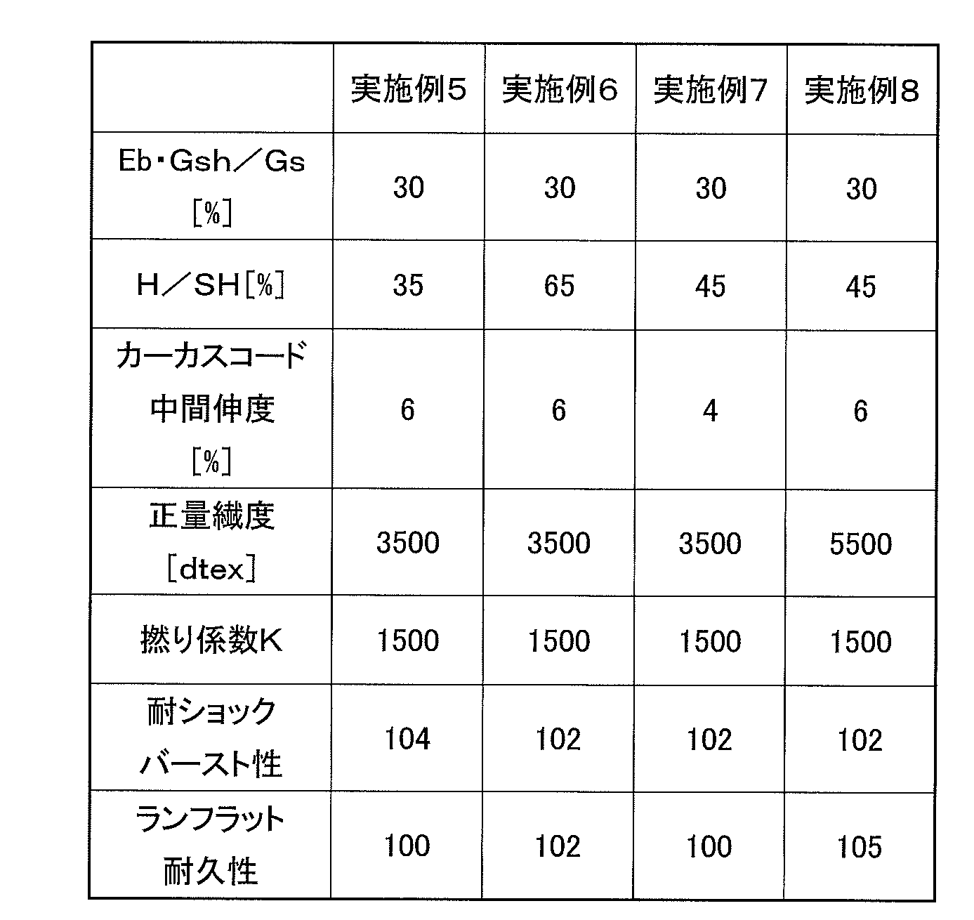
下記表1,2に示す“H/SH”は、図1に示すビードフィラーゴム22における長さHの、タイヤ断面高さSHに対する比率を示し、“カーカスコード中間伸度”は、1.5cN/dtex負荷時の伸びを示す。
In Comparative Examples 1 to 3 and Examples 1 to 8 shown in Tables 1 and 2 below, the average thickness Gsh was 10 mm or more, the average thickness Gs was 9 mm or more, and the breaking elongation Eb of the carcass cord was 20% or more. ..
“H / SH” shown in Tables 1 and 2 below indicates the ratio of the length H in the

上記表1の実施例1~4及び比較例1~3より、Eb・Gsh/Gsを18%~60%とすることにより、耐ショックバースト性及びランフラット耐久性のいずれか一方を維持しつつ、他方を向上させることができる。
上記表1,2より、ビードフィラーゴム22における長さHの、タイヤ断面高さSHに対する比率が40%以上の実施例2は、比較例1~3に対する耐ショックバースト性の向上を保ちつつ、タイヤ断面高さSHに対する比率が40%未満の実施例5に比べて、ランフラット耐久性が向上することがわかる。また、上記比率が60%超である実施例6は、実施例5に比べて耐ショックバースト性が低下することがわかる。
上記表1,2より、中間伸度(1.5cN/dtex負荷時の伸び)が5%以上である実施例2は、中間伸度が5%未満である実施例7に比べて、ランフラット耐久性が向上することがわかる。
上記表1,2より、正量繊度が4000~8000dtexの範囲内にある実施例8は、正量繊度が4000~8000dtexの範囲外にある実施例2に比べて、耐ショックバースト性を維持しつつ、ランフラット耐久性が向上することがわかる。
From Examples 1 to 4 and Comparative Examples 1 to 3 in Table 1 above, by setting Eb · Gsh / Gs to 18% to 60%, while maintaining either shock burst resistance or run-flat durability. , The other can be improved.
From Tables 1 and 2 above, in Example 2 in which the ratio of the length H of the
From Tables 1 and 2 above, Example 2 having an intermediate elongation (elongation under 1.5 cN / dtex load) of 5% or more is run-flat as compared with Example 7 having an intermediate elongation of less than 5%. It can be seen that the durability is improved.
From Tables 1 and 2 above, Example 8 having a positive fineness in the range of 4000 to 8000 dtex maintains shock burst resistance as compared with Example 2 having a positive fineness outside the range of 4000 to 8000 dtex. At the same time, it can be seen that the run-flat durability is improved.
以上、本開示のタイヤについて詳細に説明したが、本開示は上記実施形態及び実施例に限定されず、本発明の主旨を逸脱しない範囲において、種々の改良や変更してもよいのはもちろんである。 Although the tires of the present disclosure have been described in detail above, the present disclosure is not limited to the above-described embodiments and examples, and it goes without saying that various improvements and changes may be made without departing from the gist of the present invention. is there.
10 タイヤ
10T トレッド部
10S サイドウォール部
10B ビード部
12 カーカス層
14 ベルト層
14a,14b ベルト材
16 ビードコア
18 トレッドゴム
20 サイドゴム
22 ビードフィラーゴム
24 リムクッションゴム
26 インナーライナゴム
28 サイド補強ゴム層
10
Claims (8)
前記カーカス層は、有機繊維のフィラメント束を撚り合わせた有機繊維コードからなるカーカスコードで構成され、前記カーカスコードの破断伸びをEbとし、
前記サイドウォール部の、タイヤ径方向におけるタイヤ最大幅位置と、前記タイヤ最大幅位置から、タイヤ断面高さの15%の長さ分、タイヤ径方向外側に離れた位置との間の、前記サイドウォール部の平均厚さをGsとし、
前記カーカス層に直交し、前記ベルト層のうち最大幅ベルト層の最大幅位置を通る直線が前記トレッド部の表面と交差するショルダー位置と、前記ショルダー位置から、前記最大幅ベルト層の最大ベルト幅の15%の長さ分、タイヤ幅方向の内側に離れた位置との間の、前記トレッド部における平均厚さをGshとしたとき、
前記Eb、前記Gs、及び前記Gshは、
(1)Eb≧ 20%、
(2)Gsh≧ 10mm、
(3)Gs≧ 9mm、
(4)60%≧ Eb・Gsh/Gs≧ 18%
を満足することを特徴とするタイヤ。 A tread portion extending in the tire circumferential direction to form an annular shape, a pair of sidewall portions having side rubbers arranged on both sides of the tread portion, and a pair of beads arranged inside the sidewall portion in the tire radial direction. A portion, and at least one layer of carcass layer mounted between the pair of bead portions, and the sidewall portion extending toward the inner surface side of the carcass layer along the inner surface in the tire radial direction. A tire having a side rubber reinforcing layer for reinforcing the side rubber and a plurality of belt layers arranged on the outer side of the carcass layer in the tread portion in the tire radial direction.
The carcass layer is composed of a carcass cord made of an organic fiber cord obtained by twisting filament bundles of organic fibers, and the breaking elongation of the carcass cord is defined as Eb.
The side of the sidewall portion between the maximum tire width position in the tire radial direction and a position separated from the maximum tire width position by 15% of the tire cross-sectional height outward in the tire radial direction. Let Gs be the average thickness of the wall part
The shoulder position where a straight line orthogonal to the carcass layer and passing through the maximum width position of the maximum width belt layer of the belt layer intersects the surface of the tread portion, and the maximum belt width of the maximum width belt layer from the shoulder position. When the average thickness of the tread portion between the tread portion and the position separated inward in the tire width direction by 15% of the length is Gsh.
The Eb, the Gs, and the Gsh are
(1) Eb ≧ 20%,
(2) Gsh ≥ 10 mm,
(3) Gs ≧ 9 mm,
(4) 60% ≧ Eb ・ Gsh / Gs ≧ 18%
Tires that are characterized by satisfying.
前記ビードフィラーゴムの最大高さ位置の、前記ビード部のタイヤ径方向最内部の位置からタイヤ径方向に沿った長さは、前記タイヤ断面高さの40~60%である、請求項1に記載のタイヤ。 Each of the bead portions includes a bead core extending in an annular shape in the tire circumferential direction and a bead filler rubber extending outward in the tire radial direction from the bead core.
The length of the maximum height position of the bead filler rubber along the tire radial direction from the innermost position of the bead portion in the tire radial direction is 40 to 60% of the tire cross-sectional height, according to claim 1. The tires listed.
K=T×D1/2
(但し、Tは前記カーカスコードの上撚り数(回/10cm)であり、Dは前記カーカスコードの総繊度(dtex)である。) The tire according to any one of claims 1 to 7, wherein the twist coefficient K shown in the following formula after the carcass cord dipping treatment is 2000 to 2500.
K = T × D 1/2
(However, T is the number of upper twists (times / 10 cm) of the carcass cord, and D is the total fineness (dtex) of the carcass cord.)
Priority Applications (4)
| Application Number | Priority Date | Filing Date | Title |
|---|---|---|---|
| CN202080030232.5A CN113727866B (en) | 2019-05-28 | 2020-05-12 | Tire with a tire body |
| DE112020001785.0T DE112020001785T5 (en) | 2019-05-28 | 2020-05-12 | tires |
| US17/595,540 US20220258536A1 (en) | 2019-05-28 | 2020-05-12 | Tire |
| JP2021522178A JP7587159B2 (en) | 2019-05-28 | 2020-05-12 | tire |
Applications Claiming Priority (2)
| Application Number | Priority Date | Filing Date | Title |
|---|---|---|---|
| JP2019099319 | 2019-05-28 | ||
| JP2019-099319 | 2019-05-28 |
Publications (1)
| Publication Number | Publication Date |
|---|---|
| WO2020241237A1 true WO2020241237A1 (en) | 2020-12-03 |
Family
ID=73554045
Family Applications (1)
| Application Number | Title | Priority Date | Filing Date |
|---|---|---|---|
| PCT/JP2020/018952 Ceased WO2020241237A1 (en) | 2019-05-28 | 2020-05-12 | Tire |
Country Status (5)
| Country | Link |
|---|---|
| US (1) | US20220258536A1 (en) |
| JP (1) | JP7587159B2 (en) |
| CN (1) | CN113727866B (en) |
| DE (1) | DE112020001785T5 (en) |
| WO (1) | WO2020241237A1 (en) |
Cited By (2)
| Publication number | Priority date | Publication date | Assignee | Title |
|---|---|---|---|---|
| WO2021206016A1 (en) * | 2020-04-07 | 2021-10-14 | 横浜ゴム株式会社 | Pneumatic tire |
| WO2021206015A1 (en) * | 2020-04-07 | 2021-10-14 | 横浜ゴム株式会社 | Pneumatic tire |
Families Citing this family (1)
| Publication number | Priority date | Publication date | Assignee | Title |
|---|---|---|---|---|
| CN114088426B (en) * | 2022-01-20 | 2022-05-17 | 山东兴达轮胎有限公司 | Detection method for reducing early lateral falling problem of rigid-block tire and tire |
Citations (15)
| Publication number | Priority date | Publication date | Assignee | Title |
|---|---|---|---|---|
| JP2002500590A (en) * | 1997-05-29 | 2002-01-08 | ザ グッドイヤー タイヤ アンド ラバー カンパニー | Low-cost run-flat tires with improved carcass |
| JP2004175263A (en) * | 2002-11-28 | 2004-06-24 | Toyo Tire & Rubber Co Ltd | Run flat tire |
| JP2004182164A (en) * | 2002-12-05 | 2004-07-02 | Toyo Tire & Rubber Co Ltd | Run flat tire |
| JP2007161068A (en) * | 2005-12-13 | 2007-06-28 | Sumitomo Rubber Ind Ltd | Pneumatic tire |
| JP2007303056A (en) * | 2006-04-13 | 2007-11-22 | Toyobo Co Ltd | High heat resistant polyester fiber material, tire cord, dip cord, and method for producing high heat resistant polyester fiber material |
| JP2008038295A (en) * | 2006-08-08 | 2008-02-21 | Toyobo Co Ltd | High heat-resistant polyester dipped cord and method for producing the same |
| JP2009269607A (en) * | 2008-05-06 | 2009-11-19 | Goodyear Tire & Rubber Co:The | High twist polyester carcass ply for pneumatic tire |
| JP2011143899A (en) * | 2010-01-18 | 2011-07-28 | Bridgestone Corp | Pneumatic tire |
| JP2012096655A (en) * | 2010-11-02 | 2012-05-24 | Yokohama Rubber Co Ltd:The | Pneumatic run flat tire |
| JP2015000599A (en) * | 2013-06-13 | 2015-01-05 | 株式会社ブリヂストン | Run-flat tire |
| JP2015140078A (en) * | 2014-01-28 | 2015-08-03 | 株式会社ブリヂストン | Run flat tire |
| WO2016143757A1 (en) * | 2015-03-06 | 2016-09-15 | 株式会社ブリヂストン | Tire |
| JP2017210094A (en) * | 2016-05-25 | 2017-11-30 | 横浜ゴム株式会社 | Pneumatic tire |
| JP2018197019A (en) * | 2017-05-23 | 2018-12-13 | 株式会社ブリヂストン | Run-flat radial tire |
| JP2019142456A (en) * | 2018-02-23 | 2019-08-29 | 横浜ゴム株式会社 | Run-flat tire |
Family Cites Families (15)
| Publication number | Priority date | Publication date | Assignee | Title |
|---|---|---|---|---|
| JPS5615321B2 (en) * | 1973-09-20 | 1981-04-09 | ||
| JPS60185833A (en) * | 1984-03-02 | 1985-09-21 | 旭化成株式会社 | Polyester fiber dip code for reinforcing rubber |
| SU1298100A1 (en) * | 1985-11-10 | 1987-03-23 | Предприятие П/Я А-7202 | Radial pneumatic tyre |
| CN1125483C (en) * | 1997-06-16 | 2003-10-22 | 松下电器产业株式会社 | Tray storing and feeding apparatus |
| JPH11310018A (en) * | 1998-04-30 | 1999-11-09 | Bridgestone Corp | Pneumatic radial tire |
| JP2001277824A (en) * | 2000-03-31 | 2001-10-10 | Bridgestone Corp | Pneumatic run flat tire |
| US6886320B2 (en) * | 2001-05-21 | 2005-05-03 | Performance Fibers, Inc. | Process and system for producing tire cords |
| US20040078900A1 (en) * | 2002-06-03 | 2004-04-29 | Ralph Schaefer | Impregnating and bonding agent for textiles |
| JP4631496B2 (en) * | 2005-03-25 | 2011-02-16 | 横浜ゴム株式会社 | Pneumatic tire |
| JP2007283896A (en) * | 2006-04-17 | 2007-11-01 | Bridgestone Corp | Pneumatic tire |
| JP6241346B2 (en) * | 2014-03-27 | 2017-12-06 | 横浜ゴム株式会社 | Pneumatic tire |
| JP6347979B2 (en) | 2014-04-18 | 2018-06-27 | 株式会社ブリヂストン | Side-reinforced run-flat radial tire |
| JP6423177B2 (en) * | 2014-06-09 | 2018-11-14 | 株式会社ブリヂストン | Pneumatic tire |
| RU2711856C2 (en) * | 2016-07-01 | 2020-01-22 | Кордса Текник Текстил Аноним Ширкети | New bielastic tire cord from polyester as reinforcing layer of breaker |
| DE102016216081A1 (en) * | 2016-08-26 | 2018-03-01 | Continental Reifen Deutschland Gmbh | Reinforcing layer for elastomeric products, in particular for a carcass ply of a pneumatic vehicle tire, comprising a hybrid cord |
-
2020
- 2020-05-12 CN CN202080030232.5A patent/CN113727866B/en active Active
- 2020-05-12 WO PCT/JP2020/018952 patent/WO2020241237A1/en not_active Ceased
- 2020-05-12 DE DE112020001785.0T patent/DE112020001785T5/en active Pending
- 2020-05-12 JP JP2021522178A patent/JP7587159B2/en active Active
- 2020-05-12 US US17/595,540 patent/US20220258536A1/en active Pending
Patent Citations (15)
| Publication number | Priority date | Publication date | Assignee | Title |
|---|---|---|---|---|
| JP2002500590A (en) * | 1997-05-29 | 2002-01-08 | ザ グッドイヤー タイヤ アンド ラバー カンパニー | Low-cost run-flat tires with improved carcass |
| JP2004175263A (en) * | 2002-11-28 | 2004-06-24 | Toyo Tire & Rubber Co Ltd | Run flat tire |
| JP2004182164A (en) * | 2002-12-05 | 2004-07-02 | Toyo Tire & Rubber Co Ltd | Run flat tire |
| JP2007161068A (en) * | 2005-12-13 | 2007-06-28 | Sumitomo Rubber Ind Ltd | Pneumatic tire |
| JP2007303056A (en) * | 2006-04-13 | 2007-11-22 | Toyobo Co Ltd | High heat resistant polyester fiber material, tire cord, dip cord, and method for producing high heat resistant polyester fiber material |
| JP2008038295A (en) * | 2006-08-08 | 2008-02-21 | Toyobo Co Ltd | High heat-resistant polyester dipped cord and method for producing the same |
| JP2009269607A (en) * | 2008-05-06 | 2009-11-19 | Goodyear Tire & Rubber Co:The | High twist polyester carcass ply for pneumatic tire |
| JP2011143899A (en) * | 2010-01-18 | 2011-07-28 | Bridgestone Corp | Pneumatic tire |
| JP2012096655A (en) * | 2010-11-02 | 2012-05-24 | Yokohama Rubber Co Ltd:The | Pneumatic run flat tire |
| JP2015000599A (en) * | 2013-06-13 | 2015-01-05 | 株式会社ブリヂストン | Run-flat tire |
| JP2015140078A (en) * | 2014-01-28 | 2015-08-03 | 株式会社ブリヂストン | Run flat tire |
| WO2016143757A1 (en) * | 2015-03-06 | 2016-09-15 | 株式会社ブリヂストン | Tire |
| JP2017210094A (en) * | 2016-05-25 | 2017-11-30 | 横浜ゴム株式会社 | Pneumatic tire |
| JP2018197019A (en) * | 2017-05-23 | 2018-12-13 | 株式会社ブリヂストン | Run-flat radial tire |
| JP2019142456A (en) * | 2018-02-23 | 2019-08-29 | 横浜ゴム株式会社 | Run-flat tire |
Cited By (4)
| Publication number | Priority date | Publication date | Assignee | Title |
|---|---|---|---|---|
| WO2021206016A1 (en) * | 2020-04-07 | 2021-10-14 | 横浜ゴム株式会社 | Pneumatic tire |
| WO2021206015A1 (en) * | 2020-04-07 | 2021-10-14 | 横浜ゴム株式会社 | Pneumatic tire |
| US12023970B2 (en) | 2020-04-07 | 2024-07-02 | The Yokohama Rubber Co., Ltd. | Pneumatic tire |
| US12030351B2 (en) | 2020-04-07 | 2024-07-09 | The Yokohama Rubber Co., Ltd. | Pneumatic tire |
Also Published As
| Publication number | Publication date |
|---|---|
| DE112020001785T5 (en) | 2021-12-30 |
| US20220258536A1 (en) | 2022-08-18 |
| CN113727866B (en) | 2023-08-01 |
| JPWO2020241237A1 (en) | 2020-12-03 |
| JP7587159B2 (en) | 2024-11-20 |
| CN113727866A (en) | 2021-11-30 |
Similar Documents
| Publication | Publication Date | Title |
|---|---|---|
| KR101477317B1 (en) | Pneumatic tire | |
| KR102215744B1 (en) | Pneumatic tire | |
| EP2810791B1 (en) | Pneumatic tire and hybrid cord for such a pneumatic tire | |
| US20190329594A1 (en) | Pneumatic Tire | |
| JP5180562B2 (en) | Run flat tire | |
| US20150041039A1 (en) | Pneumatic tire with a reinforced flipper or chipper | |
| JP7587159B2 (en) | tire | |
| JP2009137449A (en) | Run flat tire | |
| JP6588898B2 (en) | Pneumatic tire | |
| JP5424474B2 (en) | Run flat tire | |
| CN113613873B (en) | Pneumatic tire | |
| JP5193502B2 (en) | Pneumatic tire | |
| CN113242802B (en) | Pneumatic tire | |
| EP4257371B1 (en) | Pneumatic tire | |
| JP7560745B2 (en) | Pneumatic tires | |
| JP2008126952A (en) | Pneumatic tire | |
| JP5384255B2 (en) | Pneumatic tire | |
| JP6356495B2 (en) | Pneumatic tire | |
| JP4458993B2 (en) | Run flat tire | |
| JP7305991B2 (en) | pneumatic tire | |
| KR20220038779A (en) | pneumatic tire | |
| JP5083041B2 (en) | Pneumatic tire | |
| JP5332422B2 (en) | Pneumatic tire | |
| JP5139762B2 (en) | Run flat tire | |
| JP5144290B2 (en) | Pneumatic run flat tire |
Legal Events
| Date | Code | Title | Description |
|---|---|---|---|
| 121 | Ep: the epo has been informed by wipo that ep was designated in this application |
Ref document number: 20813384 Country of ref document: EP Kind code of ref document: A1 |
|
| ENP | Entry into the national phase |
Ref document number: 2021522178 Country of ref document: JP Kind code of ref document: A |
|
| 122 | Ep: pct application non-entry in european phase |
Ref document number: 20813384 Country of ref document: EP Kind code of ref document: A1 |