WO2020241397A1 - 直流遮断器 - Google Patents
直流遮断器 Download PDFInfo
- Publication number
- WO2020241397A1 WO2020241397A1 PCT/JP2020/019864 JP2020019864W WO2020241397A1 WO 2020241397 A1 WO2020241397 A1 WO 2020241397A1 JP 2020019864 W JP2020019864 W JP 2020019864W WO 2020241397 A1 WO2020241397 A1 WO 2020241397A1
- Authority
- WO
- WIPO (PCT)
- Prior art keywords
- arc
- plate
- circuit breaker
- shielding portion
- extinguishing
- Prior art date
- Legal status (The legal status is an assumption and is not a legal conclusion. Google has not performed a legal analysis and makes no representation as to the accuracy of the status listed.)
- Ceased
Links
Images






Classifications
-
- H—ELECTRICITY
- H01—ELECTRIC ELEMENTS
- H01H—ELECTRIC SWITCHES; RELAYS; SELECTORS; EMERGENCY PROTECTIVE DEVICES
- H01H33/00—High-tension or heavy-current switches with arc-extinguishing or arc-preventing means
- H01H33/02—Details
- H01H33/04—Means for extinguishing or preventing arc between current-carrying parts
- H01H33/08—Stationary parts for restricting or subdividing the arc, e.g. barrier plate
-
- H—ELECTRICITY
- H01—ELECTRIC ELEMENTS
- H01H—ELECTRIC SWITCHES; RELAYS; SELECTORS; EMERGENCY PROTECTIVE DEVICES
- H01H73/00—Protective overload circuit-breaking switches in which excess current opens the contacts by automatic release of mechanical energy stored by previous operation of a hand reset mechanism
- H01H73/02—Details
- H01H73/18—Means for extinguishing or suppressing arc
-
- H—ELECTRICITY
- H01—ELECTRIC ELEMENTS
- H01H—ELECTRIC SWITCHES; RELAYS; SELECTORS; EMERGENCY PROTECTIVE DEVICES
- H01H9/00—Details of switching devices, not covered by groups H01H1/00 - H01H7/00
- H01H9/30—Means for extinguishing or preventing arc between current-carrying parts
- H01H9/34—Stationary parts for restricting or subdividing the arc, e.g. barrier plate
- H01H9/341—Barrier plates carrying electrodes
Definitions
- the present application relates to a DC circuit breaker having a shielding portion on the arc extinguishing plate.
- the DC circuit breaker includes a stator having a fixed contact and a mover having a movable contact that can be separated from the fixed contact, and cuts off the current by opening the contact.
- the arc generated by the opening of the pole is transferred from the contact point onto the arc runner arranged near the contact point and guided to the arc extinguishing chamber.
- a plurality of arc extinguishing plates formed by holding a grid on an insulating plate are arranged in parallel at regular intervals.
- the arc that has entered the arc extinguishing chamber is divided by the arc extinguishing plate, and an arc voltage higher than the power supply voltage of the DC circuit is generated to cut off the current limiting flow.
- Patent Document 1 and Patent Document 2 by providing a shielding portion between the contact and the arc extinguishing plate of the arc extinguishing chamber, it is possible to prevent the hot gas generated by the arc entering the arc extinguishing chamber from flowing back in the contact direction.
- the re-ignition near the contact point was suppressed.
- the control of the flow direction of the arc that has entered the arc extinguishing plate and is divided is not sufficient, and the backflow of the arc may occur, which may cause a failure of interruption.
- the present application has been made to solve the above-mentioned problems, and a shielding portion for controlling the arc flow is provided on the arc extinguishing plate of the arc extinguishing chamber so that the arc does not flow back from the grid.
- the purpose is to obtain a DC circuit breaker with high breaking performance.
- the DC circuit breaker of the present application includes a circuit breaker mechanism that opens a pole between a fixed contact and a movable contact to block a DC current, and an arc extinguishing plate formed by superimposing an insulating plate and a conductive plate-shaped grid.
- the shielding portion on the arc extinguishing plate by providing the shielding portion on the arc extinguishing plate, the arc does not flow back from the arc extinguishing plate, and high breaking performance can be obtained.
- FIG. 1 It is sectional drawing which shows the structure of the DC circuit breaker which concerns on Embodiment 1.
- FIG. It is sectional drawing which shows the structure of the DC circuit breaker which concerns on Embodiment 1.
- FIG. It is sectional drawing which shows the structure of the DC circuit breaker which concerns on Embodiment 1.
- FIG. It is a perspective view of the arc extinguishing plate which formed the shielding part which concerns on Embodiment 1.
- FIG. It is a partial perspective view which shows the modification of the arc extinguishing plate which formed the shielding part which concerns on Embodiment 1.
- FIG. It is a perspective view which shows the structure of the arc extinguishing chamber which concerns on Embodiment 1.
- FIG. 1 It is an image figure which shows the effect of the shielding part which concerns on Embodiment 1.
- FIG. 2 It is sectional drawing which shows the structure of the DC circuit breaker which concerns on Embodiment 1.
- FIG. It is an image figure which shows the effect of the shielding part which concerns on Embodiment 1.
- FIG. It is a perspective view of the arc runner which formed the shielding part which concerns on Embodiment 2.
- FIGS. 1 to 7. are schematic cross-sectional views showing a schematic structure of the DC circuit breaker 100 of the present embodiment, FIG. 1 shows a closed pole state between contacts, and FIG. 2 shows an open pole state.
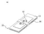
- FIG. 3 is a perspective view showing several arc-extinguishing plates 15 arranged in the arc-extinguishing chamber 14 of the DC circuit breaker 100, and is shielded by the arc-extinguishing plate 15 formed by the insulating plate 13 and the grid 12. The state in which the part 30 is formed is shown.
- FIG. 4 shows the structure of the back surface of FIG. 3, and FIG. 5 shows an example of changing the arrangement of the grid 12.
- FIG. 4 shows the structure of the back surface of FIG. 3
- FIG. 5 shows an example of changing the arrangement of the grid 12.
- FIG. 6 shows the internal structure of the arc extinguishing chamber 14, and shows a structure in which an arc extinguishing plate 15 composed of an insulating plate 13 and a grid 12 and having a shielding portion 30 formed therein is laminated.
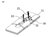
- FIG. 7 shows the flow of hot gas by the shielding portion 30.
- FIGS. 1 and 2 are cross-sectional views of the DC circuit breaker 100 of the present embodiment, showing a schematic structure of the apparatus.
- the lower part shows the breaking mechanism part 16 and the upper part shows the arc extinguishing chamber 14.
- the cutoff mechanism portion 16 of FIG. 1 shows a closed pole state of the contact.
- the mover 4 is pushed to the left in the figure by the closing actuator 5, and the movable contact 3 attached to the mover 4 is in contact with the fixed contact 1 attached to the stator 2, and is in contact with the upper conductor 6. It can be energized between it and the lower conductor 7.
- the arc extinguishing chamber 14 in the upper part of the figure has a space above the fixed contact 1 and the movable contact 3, and the fixed arc runner 10 and the movable arc runner 11 are arranged on the left and right.
- the shielding portions 30 made of the same material are integrated and arranged in a laminated manner.
- the member in the arc extinguishing chamber 14 composed of the grid 12 and the insulating plate 13 is referred to as an arc extinguishing plate 15.
- the linear convex portion arranged on the arc extinguishing plate 15 is called a shielding portion 30.
- the portion surrounded by the broken line in the arc extinguishing chamber 14 indicates the arc extinguishing plate 15.
- the arc-extinguishing plate 15 has a grid 12 attached to the upper surface of the insulating plate 13, and the insulating plate 13 is further formed with a shielding portion 30 starting from the edge of the arc-extinguishing plate 15.
- the shielding portion 30 on the insulating plate 13 can be formed integrally with the insulating plate 13. Further, the shielding portion 30 may be formed as a separate member, and may be mounted and arranged on the insulating plate 13.
- the stacking order of the insulating plate 13, the grid 12, and the shielding portion 30 constituting the arc extinguishing plate 15 is an example, and the order of the insulating plate 13 and the grid 12 can be changed as described later. Further, in the present embodiment, the shielding portion 30 is formed on the insulating plate 13, but can be formed on the grid 12. Since FIG. 1 shows a closed pole state, electricity is applied between the fixed contact 1 and the movable contact 3, and no arc is generated. The flow when an arc is generated will be described with reference to FIG. 2 and the like.
- the blocking mechanism unit 16 in FIG. 2 shows an open pole state.
- the detector 8 installed on the lower conductor 7 detects it, and the closing actuator 5 releases the latch 9 holding the mover 4.
- the mover 4 holding the movable contact 3 moves, and the fixed contact 1 and the movable contact 3 are opened in a state where a current is applied.
- an arc 20 is generated between the fixed contact 1 and the movable contact 3.
- the stage in which the arc 20 is generated as the open pole state is called an arc, and may be distinguished from other stages of the arc 20.
- the arc 20 generated between the contacts moves between the fixed side arc runner 10 and the movable side arc runner 11.
- This stage is called commutation of the arc 21.
- the arc 21 moves to the arc extinguishing chamber 14 due to the influence of the electromagnetic force due to the current flowing through the fixed side arc runner 10 and the movable side arc runner 11 and the flow of the conductive hot gas.
- This stage is called running the arc 22.
- the arc 22 that has traveled to the arc extinguishing chamber 14 enters between the arc extinguishing plates 15.
- the stage of being divided between the plurality of arc extinguishing plates 15 is sometimes called division of the arc 23.
- the insulating plate 13 of the arc extinguishing plate 15 is prevented.
- a shielding portion 30 is formed on the surface of the arc-extinguishing plate 15 starting from the edge of the arc-extinguishing plate 15. The arrangement, structure, function, and the like of the shielding portion 30 will be described below with reference to FIGS. 3 to 7.
- FIG. 3 is a diagram showing the arrangement and structure of the shielding portion 30 formed on the insulating plate 13 of the arc extinguishing plate 15, and a part thereof is extracted from a plurality of arc extinguishing plates 15 arranged in the arc extinguishing chamber 14.
- FIG. 4 shows the structure of the back surface of FIG. 3
- FIG. 5 shows a modified example of the structure of the arc extinguishing plate 15 in which the arrangement of the grid 12 is changed.
- FIG. 6 shows an outline of the structure of the arc extinguishing plate 15 arranged inside the arc extinguishing chamber 14, and a part of the fixed arc runner 10 and the movable arc runner 11 and the like. As shown in FIG.
- the shielding portion 30 is formed on the insulating plate 13 of the arc extinguishing plate 15, and when installed in the arc extinguishing chamber 14, the shielding portion 30 is formed as shown in FIG. The surface is arranged facing down.
- the side of the insulating plate 13 on which the shielding portion 30 is formed is shown facing upward.
- the arc extinguishing plate 15 is composed of a grid 12 and an insulating plate 13 and has a structure in which a shielding portion 30 is formed.
- the grid 12 can be observed due to the influence of the observation angle. Can not.
- the insulating plate 13 has a square opening formed in the center for the traveling arc 22 to flow, and the grid 12 is projected and laminated in this opening. As shown in FIGS. 1 and 2, this opening is arranged directly above the fixed contact 1 and the movable contact 3. That is, as shown in FIG. 2, the arc 20 generated by the opening operation of the fixed contact 1 and the movable contact 3 is opened by the electromagnetic force of the fixed side arc runner 10 and the movable side arc runner 11 and the flow of hot gas. It flows into the arc-extinguishing plate 15, enters between the arc-extinguishing plates 15, and is divided by the grid 12 arranged on the arc-extinguishing plate 15.
- the shielding portion 30 has a convex shape arranged linearly, and the side surface of the convex portion is attached to the insulating plate 13 in close contact with the insulating plate 13. Further, the shielding portion 30 starts from the edge of the square opening formed in the center of the insulating plate 13 of the arc-extinguishing plate 15 and faces the outside of the insulating plate 13 to substantially the outer peripheral edge of the arc-extinguishing plate 15. They are arranged in a radial pattern. The position where the shielding portion 30 is formed is preferably formed in the region where the grid 12 is arranged on the arc extinguishing plate 15.
- the grid 12 may be laminated on the arc extinguishing plate 15 and formed at a position corresponding to the formation position of the grid 12 on the surface of the grid 12 or on the opposite surface of the surface on which the grid 12 is formed.
- the shielding portion 30 by arranging the shielding portion 30 starting from the region where the grid 12 protrudes into the square opening of the arc extinguishing plate 15 shown in FIG. 3, the arc control effect can be enhanced.
- the thickness of the shielding portion 30 is the same level as that of the grid 12 and the insulating plate 13 so as not to significantly affect the laminated structure when the arc extinguishing plates 15 are laminated with each other and arranged in the arc extinguishing chamber 14. It is thick.
- FIG. 4 shows the structure of the back surface of the arc extinguishing plate 15 shown in FIG. 3, and a convex portion is formed in the central portion in the longitudinal direction of the arc extinguishing plate 15 on which the grid 12 is not arranged.
- FIG. 5 is a modified example in which the grid 12 is arranged between the insulating plate 13 and the shielding portion 30. A good arc control effect can also be obtained by this arrangement.
- FIG. 7 shows the flow of the arc 22 and the hot gas traveling between the arc extinguishing plates 15.
- the effect of the shielding portion 30 on the arc 23 divided by the arc extinguishing plate 15 will be described with reference to FIG. 7.
- FIG. 7 also shows a state in which the surface of the insulating plate 13 of the arc extinguishing plate 15 on which the shielding portion 30 is formed faces upward for the sake of explanation.
- the divided arc 23 spreads in all directions, but since the shape of the insulating plate 13 of the arc extinguishing plate 15 has symmetry with respect to the central square opening, the diffusion of the arc 23 is also symmetric. Has sex. Therefore, for the sake of simplicity, the explanation will be given in only one direction.
- the arc 20 generated by the opening of the fixed contact 1 and the movable contact 3 moves and travels to the central square opening portion in FIG. 7.
- the arc 22 traveling on the fixed side arc runner 10 and the movable side arc runner 11 is affected by the electromagnetic force of the grid 12 of the arc extinguishing plate 15 and the flow of hot gas, and is along the white arrow 32 indicating the traveling of the arc 22 in the drawing. It moves and becomes a divided arc 23.
- the highly conductive hot gas generated by the arc 23 moves along the surface of the arc extinguishing plate 15 and diffuses radially as shown by the black arrow 31 indicating the flow of the hot gas.
- the shielding portion 30 is not arranged on the insulating plate 13, a part of the diffused hot gas may wrap around from the side and move toward the center of the arc extinguishing plate 15 again. In that case, the re-pointing point It is also possible that an arc or the like is generated.
- a shielding portion 30 having a linear convex shape bent at an obtuse angle and having the bent portions facing each other is formed on the edge of the central opening. Is formed from the starting point to the outer peripheral edge of the arc extinguishing plate 15. Therefore, the hot gas diffuses as shown by the black arrow 31, and the hot gas wrapping around from the side can be received at the bent portion and diffused radially to the outside of the arc extinguishing plate 15.
- the backflow of hot gas generated by the divided arc 23 can be prevented, the hot gas can be diffused to the outside of the arc extinguishing plate 15, and can be discharged to the vicinity of the housing of the arc extinguishing chamber 14. This makes it possible to prevent the arc from reigniting and improve the breaking characteristics of the DC circuit breaker 100.
- a bent-shaped shielding portion 30 is formed on the lower surface of the insulating plate 13 by using the same resin material as the insulating plate 13, but the present invention is not limited to this, and another insulating material is used.
- the same effect can be obtained by creating a linear or bent convex shielding portion 30 using the above and attaching it to the insulating plate 13 by pasting or screwing.
- the configuration in which the shielding portion 30 is attached to the lower surface of the insulating plate 13 of the arc extinguishing plate 15 has been described, but the shielding portion 30 having a linear or bent convex shape is formed on the upper surface of the insulating plate 13. Even if it is formed, the same effect can be obtained.
- the shielding portion 30 is formed on the insulating plate 13 using an insulating material, but a linear or bent convex shielding portion using a metal material on the grid 12 of the arc extinguishing plate 15. 30 can be formed and the side surface of the shielding portion 30 can be closely fixed on the grid by welding. Further, the grid 12 can be half-punched by press working to form the shielding portion 30.
- the arc extinguishing chamber 14 in which the arc extinguishing plate 15 composed of the insulating plate 13 and the grid 12 is horizontally arranged is used, but it is similar to the DC circuit breaker 101 shown in the cross section in FIG. Further, in the arc extinguishing chamber 14 in which the arc extinguishing plate 15 composed of the insulating plate 13 and the grid 12 is arranged in the vertical direction, the same effect can be obtained by similarly forming the shielding portion 30 in the insulating plate 13 or the grid 12. be able to.
- FIG. 9 shows the flow of hot gas and the arc 22 traveling between the arc extinguishing plates 15 arranged in the vertical direction.
- the arc 20 generated by the opening of the fixed contact 1 and the movable contact 3 is shown in FIG. Move and run to the central opening.
- the arc 22 is affected by the electromagnetic force of the grid 12 of the arc extinguishing plate 15 and the flow of hot gas, and moves along the white arrow 32 indicating the running of the arc 22 in the figure to become a divided arc 23.
- the highly conductive hot gas generated by the arc 23 can move along the surface of the arc extinguishing plate 15 and diffuse radially, as shown by the black arrow 31 indicating the flow of the hot gas.
- the shielding portion 30 in which the bent portions are arranged so as to face each other is used. Further, an example is shown in which four shielding portions 30 extending from the edge of the central opening to the edge on the outer peripheral side are used in one arc extinguishing plate 15. However, it is important that the shielding portion 30 formed on the arc extinguishing plate 15 moves the hot gas to the outside, and the ratio in the vertical direction and the horizontal direction is not limited to the bent shape and the linear convex shape. Any greatly different cylindrical type, prismatic type, or the like can be used, and the length extending to the outer peripheral edge is not always necessary. The number is not limited to four, and any one or more can be used.
- Embodiment 2 In the first embodiment, a plurality of arc-extinguishing plates 15 in which the insulating plate 13 and the grid 12 are overlapped are arranged in the arc-extinguishing chamber 14, and a shielding portion 30 is formed on the surface of the insulating plate 13 or the grid 12. An example was shown.
- the present embodiment is basically the same as the first embodiment in that the shielding portion 30 is formed starting from the edge of the central opening, but is in contact with the side surfaces of the fixed side arc runner 10 and the movable side arc runner 11. It is characterized in that it forms a shielding portion 33.
- FIG. 10 is a perspective view of the lowermost arc-extinguishing plate 15 connected to the fixed-side arc runner 10 and the movable-side arc runner 11, and the movable contact 3, the mover 4, and the upper conductor 6 are arranged under the arc runner.
- Indicates the state of The fixed side arc runner 10 and the movable side arc runner 11 are fixed by projecting a part of each arc runner on the surface of the arc extinguishing plate 15, and a bent-shaped shielding portion 33 is formed on the protruding portion of each arc runner.
- the tip portions of 33 are connected and arranged so as to radiate on the surface of the insulating plate 13.
- the backflow of hot gas generated by the divided arc 23 can be prevented, the hot gas can be diffused to the outside of the insulating plate 13 of the arc extinguishing plate 15, and is discharged to the vicinity of the housing of the arc extinguishing chamber 14. be able to.
- the arc 22 is a region where the arc 22 travels at high speed near the arc runner, the effect of preventing backflow can be remarkably obtained. This makes it possible to prevent the arc from reigniting and improve the breaking characteristics of the DC circuit breaker 100.
- the shielding portion 33 is formed on the insulating plate 13 connected to the lowermost arc runner in the arc extinguishing chamber 14, but the present invention is not limited to this, and the shielding portion 33 is formed on the grid 12.
- the same effect can be obtained by forming the shielding portion 33.
- the installation location of the shielding portion 33 is not limited to the position in contact with the side surface of the arc runner, and may be around the arc runner, and the inner wall of the arc extinguishing chamber 14 holding the stator 2 and the mover 4 and the circuit breaker. Even if the shielding portion 33 is formed on the frame portion constituting the main body, the same effect can be obtained.
- the arc runner By simultaneously using the shielding portion 33 arranged in contact with the side surface, it is possible to prevent the arc from reigniting and improve the breaking characteristics of the DC circuit breaker 100.
Landscapes
- Arc-Extinguishing Devices That Are Switches (AREA)
Abstract
固定接点(1)と可動接点(3)との間を開極して直流電流を遮断する遮断機構部(16)と、絶縁プレート(13)及び導電性を有する板状のグリッド(12)を重ね合わせてなる消弧板(15)を一定間隔で複数枚積層して内部に収納した消弧室(14)とを備えた直流遮断器であって、消弧板(15)のいずれかの表面に凸形状の遮蔽部を、消弧板の縁辺を起点として配置することで、グリッド(12)上からアークが周囲に漏れることがない、高い遮断性能を備える。
Description
本願は、消弧板に遮蔽部を有する直流遮断器に関するものである。
直流遮断器では、固定接点を有する固定子と,固定接点に対して切離自在な可動接点を有する可動子とを備え、接点の開極により電流の遮断を行う。開極に伴って発生するアークは接点から接点近傍に配置されたアークランナ上に移行させ消弧室へ導かれる。
消弧室内には、絶縁プレートにグリッドが保持されて形成された複数の消弧板が、一定間隔で平行に配置されている。消弧室に進入したアークは消弧板で分断され、直流回路の電源電圧以上のアーク電圧が発生することで事故電流の限流遮断が行われる。
消弧室内には、絶縁プレートにグリッドが保持されて形成された複数の消弧板が、一定間隔で平行に配置されている。消弧室に進入したアークは消弧板で分断され、直流回路の電源電圧以上のアーク電圧が発生することで事故電流の限流遮断が行われる。
従来の直流遮断器では、消弧室内の消弧板上に進入したアークが、限流遮断中に接点方向に逆流し、再点弧が生じる場合がある。その結果、遮断完了までの長時間化を招き、時には遮断失敗となる場合もある。
そこで、特許文献1及び特許文献2では、接点と消弧室の消弧板の間に遮蔽部を設けることで、消弧室に進入したアークにより発生したホットガスが接点方向への逆流することを防止し、接点近傍での再点弧を抑制していた。しかし、消弧板に進入し分断されたアークの流動方向の制御は十分ではなく、アークの逆流が生じ、遮断の失敗を引き起こす場合があるという問題があった。
そこで、特許文献1及び特許文献2では、接点と消弧室の消弧板の間に遮蔽部を設けることで、消弧室に進入したアークにより発生したホットガスが接点方向への逆流することを防止し、接点近傍での再点弧を抑制していた。しかし、消弧板に進入し分断されたアークの流動方向の制御は十分ではなく、アークの逆流が生じ、遮断の失敗を引き起こす場合があるという問題があった。
本願は、上記のような課題を解決するためになされたものであって、消弧室の消弧板上にアークの流れを制御する遮蔽部を設け、グリッド上からアークが逆流することがなく、遮断性能の高い直流遮断器を得ることを目的とする。
本願の直流遮断器は、固定接点と可動接点との間を開極して直流電流を遮断する遮断機構部と、絶縁プレート及び導電性を有する板状のグリッドを重ね合わせてなる消弧板と、消弧板の縁辺を固定接点と可動接点との上部に配置し、消弧板を一定間隔で複数枚積層して内部に収納した消弧室と、を備えた直流遮断器であって、消弧板のいずれかの表面に凸形状の遮蔽部を、消弧板の縁辺を起点として配置したことを特徴とするものである。
本願の直流遮断器は、遮蔽部を消弧板上に設けることによって、消弧板上からアークが逆流することがなく、高い遮断性能を得ることができる。
実施の形態の説明及び各図において、同一の符号を付した部分は、同一又は相当する部分を示すものである。
実施の形態1.
本実施の形態について、図1~図7を主に用いて説明する。図1及び図2は、本実施の形態の直流遮断器100の概略構造を示す断面模式図で、図1は接点間の閉極状態、図2は開極状態を示している。図3は、直流遮断器100の消弧室14に配置された数枚の消弧板15を抜き出して示した斜視図で、絶縁プレート13とグリッド12とで形成された消弧板15に遮蔽部30を形成した状態を示している。図4は図3の裏面の構造を示しており、図5はグリッド12の配置の変更例を示している。
図6は、消弧室14の内部の構造を示しており、絶縁プレート13とグリッド12とからなり、遮蔽部30が形成された消弧板15が積層された構造を示している。図7は、遮蔽部30によるホットガスの流れを示している。
本実施の形態について、図1~図7を主に用いて説明する。図1及び図2は、本実施の形態の直流遮断器100の概略構造を示す断面模式図で、図1は接点間の閉極状態、図2は開極状態を示している。図3は、直流遮断器100の消弧室14に配置された数枚の消弧板15を抜き出して示した斜視図で、絶縁プレート13とグリッド12とで形成された消弧板15に遮蔽部30を形成した状態を示している。図4は図3の裏面の構造を示しており、図5はグリッド12の配置の変更例を示している。
図6は、消弧室14の内部の構造を示しており、絶縁プレート13とグリッド12とからなり、遮蔽部30が形成された消弧板15が積層された構造を示している。図7は、遮蔽部30によるホットガスの流れを示している。
図1及び図2は、本実施の形態の直流遮断器100の断面図で、装置の概略構造を示している。図1及び図2に示した直流遮断器100のうち、下部分は遮断機構部16であり、上部分は消弧室14を示している。
図1の遮断機構部16は、接点の閉極状態を示している。可動子4が投入アクチュエータ5によって、図の左方向へ押され、可動子4に取付けられた可動接点3が、固定子2に取付けられた固定接点1と接触した状態であり、上部導体6と下部導体7との間に通電することができる。
図1の遮断機構部16は、接点の閉極状態を示している。可動子4が投入アクチュエータ5によって、図の左方向へ押され、可動子4に取付けられた可動接点3が、固定子2に取付けられた固定接点1と接触した状態であり、上部導体6と下部導体7との間に通電することができる。
図の上部分の消弧室14は、固定接点1と可動接点3との上部には空間を有しており、左右に固定側アークランナ10と可動側アークランナ11とが配置されている。その上には導電性を有する平板状のグリッド12と、このグリッド12を配置して保持するための絶縁プレート13と、ホットガスの逆流を防止するための線状の凸形状に形成された樹脂製の遮蔽部30が一体となり、積層して配置されている。
本実施の形態においては、このグリッド12と絶縁プレート13とからなる消弧室14内の部材を消弧板15と呼ぶ。また、消弧板15上に配置された線状の凸形状の部分を遮蔽部30と呼ぶ。
図1中では、消弧室14の中の破線で囲んだ部分が消弧板15を示している。消弧板15は、絶縁プレート13の上面にグリッド12が取り付けられており、絶縁プレート13には、さらに消弧板15の縁辺を起点として遮蔽部30が形成されている。
この絶縁プレート13上の遮蔽部30は、絶縁プレート13と一体として形成することができる。また遮蔽部30を別部材として形成し、絶縁プレート13上に取付けて配置することもできる。
本実施の形態においては、このグリッド12と絶縁プレート13とからなる消弧室14内の部材を消弧板15と呼ぶ。また、消弧板15上に配置された線状の凸形状の部分を遮蔽部30と呼ぶ。
図1中では、消弧室14の中の破線で囲んだ部分が消弧板15を示している。消弧板15は、絶縁プレート13の上面にグリッド12が取り付けられており、絶縁プレート13には、さらに消弧板15の縁辺を起点として遮蔽部30が形成されている。
この絶縁プレート13上の遮蔽部30は、絶縁プレート13と一体として形成することができる。また遮蔽部30を別部材として形成し、絶縁プレート13上に取付けて配置することもできる。
消弧板15を構成する絶縁プレート13、グリッド12と遮蔽部30の積層順序は一例であり、後述するように絶縁プレート13とグリッド12の順序を変えることも可能である。また、本実施の形態では、遮蔽部30は絶縁プレート13上に形成されているが、グリッド12上に形成することができる。
なお、図1は、閉極状態を示しているため、固定接点1と可動接点3との間に通電されており、アークは生じていない。アークが発生した時の流れは図2等を用いて説明する。
なお、図1は、閉極状態を示しているため、固定接点1と可動接点3との間に通電されており、アークは生じていない。アークが発生した時の流れは図2等を用いて説明する。
図2の遮断機構部16は、開極状態を示している。
事故電流が遮断機構部16を流れると、下部導体7に設置された検出器8が検知し、投入アクチュエータ5により可動子4を保持していたラッチ9を解除する。これにより可動接点3を保持していた可動子4が移動し、電流が印加された状態で固定接点1と可動接点3とが開極される。この開極時に固定接点1と可動接点3との間にアーク20が生じる。なお、開極状態としてアーク20を生じる段階を発弧と呼び、アーク20のその他の段階と区別する場合がある。
事故電流が遮断機構部16を流れると、下部導体7に設置された検出器8が検知し、投入アクチュエータ5により可動子4を保持していたラッチ9を解除する。これにより可動接点3を保持していた可動子4が移動し、電流が印加された状態で固定接点1と可動接点3とが開極される。この開極時に固定接点1と可動接点3との間にアーク20が生じる。なお、開極状態としてアーク20を生じる段階を発弧と呼び、アーク20のその他の段階と区別する場合がある。
接点間に発弧したアーク20は、固定側アークランナ10と可動側アークランナ11との間を移動する。この段階をアーク21の転流と呼ぶ。その後アーク21は、固定側アークランナ10、および可動側アークランナ11に流れる電流による電磁力、導電性のホットガスの流れの影響により消弧室14に移動する。この段階はアーク22の走行と呼ぶ。
消弧室14へ走行したアーク22は、消弧板15間に進入する。この複数の消弧板15間に分けられる段階をアーク23の分断と呼ぶことがある。この分断状態を維持することでアーク電圧が上昇し、回路の電源電圧以上となることで限流遮断が行われる。
本実施の形態においては図2に示したように、アーク23の消弧板15の間からの逆流を防止し、ホットガスによる再点弧を防止するために、消弧板15の絶縁プレート13の面に、消弧板15の縁辺を起点として遮蔽部30が形成されている。
以下に、図3~図7を用いて、遮蔽部30の配置、構造及び機能等を説明する。
以下に、図3~図7を用いて、遮蔽部30の配置、構造及び機能等を説明する。
図3は、消弧板15の絶縁プレート13に形成された遮蔽部30の配置及び構造を示す図であり、消弧室14内に配置された複数の消弧板15から一部を抜き出して示している。
図4は、図3の裏面の構造を示しており、図5はグリッド12の配置を変更した消弧板15の構造である変更例を示している。
図6は、消弧室14の内部に配置された消弧板15の構造の概略と、一部に固定側アークランナ10、可動側アークランナ11等を合わせて示している。
図6に示すように本実施の形態においては、遮蔽部30は消弧板15の絶縁プレート13に形成され、消弧室14に設置された場合、図4に示すように遮蔽部30を形成した面は下を向いて配置されている。
図4は、図3の裏面の構造を示しており、図5はグリッド12の配置を変更した消弧板15の構造である変更例を示している。
図6は、消弧室14の内部に配置された消弧板15の構造の概略と、一部に固定側アークランナ10、可動側アークランナ11等を合わせて示している。
図6に示すように本実施の形態においては、遮蔽部30は消弧板15の絶縁プレート13に形成され、消弧室14に設置された場合、図4に示すように遮蔽部30を形成した面は下を向いて配置されている。
なお、図3では、説明を容易にするため、遮蔽部30を形成した絶縁プレート13の側を上向きとして示している。
また、消弧板15は、グリッド12と絶縁プレート13とからなり、遮蔽部30が形成された構造をしているが、図6においては、観察角度の影響で、グリッド12は観察することができない。
また、消弧板15は、グリッド12と絶縁プレート13とからなり、遮蔽部30が形成された構造をしているが、図6においては、観察角度の影響で、グリッド12は観察することができない。
図3において、絶縁プレート13は中央に、走行するアーク22が流れるための四角い開口が形成されており、この開口には、グリッド12が突出して積層されている。この開口は、図1及び図2に示すように、固定接点1と可動接点3との直上に配置されている。つまり、図2に示したように、固定接点1と可動接点3との開極動作により生じたアーク20が、固定側アークランナ10と可動側アークランナ11の電磁力、ホットガスの流れによって、この開口に流れ込み、消弧板15間に進入し、消弧板15上に配置されたグリッド12により分断される。
図3に示すように、遮蔽部30は、線状に配置された凸形状をしており、凸形状の部分の側面を絶縁プレート13に密着させて取り付けられている。さらに、遮蔽部30は、消弧板15の絶縁プレート13の中央に形成された四角い開口の縁辺を起点として、絶縁プレート13の外側に向いて、消弧板15の外周側の縁辺まで、ほぼ放射状に配置されている。
遮蔽部30を形成する位置としては、消弧板15にグリッド12が配置された領域に形成されることが好ましい。具体的には、消弧板15にグリッド12が積層され、そのグリッド12の面上、又はグリッド12が形成された面の反対面のグリッド12の形成位置に対応する位置に形成されることが好ましい。
さらに、図3に示した消弧板15の四角い開口にグリッド12が突出した領域を起点として遮蔽部30を配置することで、アークの制御効果を高めることができる。
また、遮蔽部30の厚みは、消弧板15を相互に積層して消弧室14に配置する際に、積層構造に大きな影響を与えないように、グリッド12及び絶縁プレート13と同レベルの厚みとなっている。
遮蔽部30を形成する位置としては、消弧板15にグリッド12が配置された領域に形成されることが好ましい。具体的には、消弧板15にグリッド12が積層され、そのグリッド12の面上、又はグリッド12が形成された面の反対面のグリッド12の形成位置に対応する位置に形成されることが好ましい。
さらに、図3に示した消弧板15の四角い開口にグリッド12が突出した領域を起点として遮蔽部30を配置することで、アークの制御効果を高めることができる。
また、遮蔽部30の厚みは、消弧板15を相互に積層して消弧室14に配置する際に、積層構造に大きな影響を与えないように、グリッド12及び絶縁プレート13と同レベルの厚みとなっている。
消弧板15の間に分断されたアーク23が流入した際の、遮蔽部30の詳細な効果は後述するが、遮蔽部30は絶縁プレート13の外側に向いて放射状に配置されているため、ホットガスの拡散に有利である。また、遮蔽部30は鈍角に折れ、折れ曲がり部分を相互に対向して配置しており、折れ曲がりの凸部分によってホットガスの逆流を防止することができ、再発弧を防止することができる。
図4は、図3に示した消弧板15の裏面の構造を示しており、グリッド12を配置しない消弧板15の長手方向の中央部分に凸部が形成されている。この凸部だけではアーク23の制御効果は小さいが、図3に示した遮蔽部30と合わせて用いることで良好なアーク制御効果が期待できる。
図5はグリッド12を絶縁プレート13と遮蔽部30の間に配置した変更例である。この配置によっても良好なアーク制御効果を得ることができる。
図4は、図3に示した消弧板15の裏面の構造を示しており、グリッド12を配置しない消弧板15の長手方向の中央部分に凸部が形成されている。この凸部だけではアーク23の制御効果は小さいが、図3に示した遮蔽部30と合わせて用いることで良好なアーク制御効果が期待できる。
図5はグリッド12を絶縁プレート13と遮蔽部30の間に配置した変更例である。この配置によっても良好なアーク制御効果を得ることができる。
図7は消弧板15間へ走行したアーク22とホットガスの流れを示している。図7を用いて消弧板15で分断されたアーク23に対する遮蔽部30の効果を説明する。図3と同様に、図7においても説明のために、遮蔽部30が形成された消弧板15の絶縁プレート13の面を上向きとした状態を示している。なお、分断されたアーク23は、全方位に向けて広がっていくが、消弧板15の絶縁プレート13の形状が、中央の四角い開口に対して対称性を有するため、アーク23の拡散も対称性を有する。そこで説明を容易とするため、一方向に限って説明する。
固定接点1と可動接点3との開極に伴い発弧したアーク20は、図7の中央の四角い開口部分へ移動、走行する。固定側アークランナ10、可動側アークランナ11を走行したアーク22は、消弧板15のグリッド12の電磁力、ホットガスの流れに影響され、図中のアーク22の走行を示す白矢印32に沿って移動し、分断されたアーク23となる。
さらに、アーク23により発生した導電性の高いホットガスは、ホットガスの流れを示す黒矢印31に示すように、消弧板15の面に沿って移動し、放射状に拡散する。
さらに、アーク23により発生した導電性の高いホットガスは、ホットガスの流れを示す黒矢印31に示すように、消弧板15の面に沿って移動し、放射状に拡散する。
仮に、絶縁プレート13上に遮蔽部30が配置されていない場合、拡散したホットガスの一部は横から回り込み、再び消弧板15の中央方向に移動する可能性があり、その場合、再点弧等を生じる場合も考えられる。しかし、図7に示すように、消弧板15の絶縁プレート13上には、鈍角に折れ曲がった線状の凸形状で、折れ曲がり部分を相互に対向させた遮蔽部30が、中央の開口の縁辺を起点として、消弧板15の外周側の縁辺まで形成されている。そのため、ホットガスが黒矢印31に示すように拡散し、横から回り込むホットガスを折れ曲がり部分で受け、消弧板15の外側へ放射状に拡散させることができる。
以上より、分断されたアーク23により生じるホットガスの逆流を防止し、ホットガスを、消弧板15の外側へ拡散させることができ、消弧室14の筐体付近まで放出することができる。これにより、アークの再点弧を防止し、直流遮断器100の遮断特性を向上させることができる。
本実施の形態1においては、絶縁プレート13の下面に、絶縁プレート13と同様の樹脂材料を用いて折れ曲がった形状の遮蔽部30を形成したが、これに限定するものではなく、別の絶縁材料を用いて線状又は折れ曲がった凸形状の遮蔽部30を作成し、貼り付け又はねじ止めにより絶縁プレート13に取り付けても同様の効果を得ることができる。
また、本実施の形態においては、消弧板15の絶縁プレート13の下面に遮蔽部30を取り付けた構成について述べたが、絶縁プレート13の上面に線状又は折れ曲がった凸形状の遮蔽部30に形成しても同様の効果を得ることができる。
また、本実施の形態においては、消弧板15の絶縁プレート13の下面に遮蔽部30を取り付けた構成について述べたが、絶縁プレート13の上面に線状又は折れ曲がった凸形状の遮蔽部30に形成しても同様の効果を得ることができる。
また、本実施の形態1では、絶縁プレート13に絶縁材料を用いて遮蔽部30を形成したが、消弧板15のグリッド12上に金属材料を用いて線状又は折れ曲がった凸形状の遮蔽部30を形成し、溶接によりグリッド上に遮蔽部30の側面を密着して固定することもできる。また、グリッド12をプレス加工による半抜き加工を行い、遮蔽部30を形成することもできる。
さらに、本実施の形態1では、絶縁プレート13とグリッド12とからなる消弧板15を水平に配置した消弧室14を用いたが、図8に断面図で示した直流遮断器101のように、絶縁プレート13とグリッド12とからなる消弧板15を垂直方向に配置した消弧室14においても、同様に絶縁プレート13又はグリッド12に遮蔽部30を形成することで同様の効果を得ることができる。
図9は垂直方向に配置した消弧板15間へ走行したアーク22とホットガスの流れを示している
固定接点1と可動接点3との開極に伴い発弧したアーク20は、図9の中央の開口部分へ移動、走行する。アーク22は、消弧板15のグリッド12の電磁力、ホットガスの流れに影響され、図中のアーク22の走行を示す白矢印32に沿って移動し、分断されたアーク23となる。
さらに、アーク23により発生した導電性の高いホットガスは、ホットガスの流れを示す黒矢印31に示すように、消弧板15の面に沿って移動し、放射状に拡散させることができる。
図9は垂直方向に配置した消弧板15間へ走行したアーク22とホットガスの流れを示している
固定接点1と可動接点3との開極に伴い発弧したアーク20は、図9の中央の開口部分へ移動、走行する。アーク22は、消弧板15のグリッド12の電磁力、ホットガスの流れに影響され、図中のアーク22の走行を示す白矢印32に沿って移動し、分断されたアーク23となる。
さらに、アーク23により発生した導電性の高いホットガスは、ホットガスの流れを示す黒矢印31に示すように、消弧板15の面に沿って移動し、放射状に拡散させることができる。
本実施の形態1においては、折れ曲がり部分を相互に対向して配置した遮蔽部30を用いた。また1つの消弧板15に、中央の開口の縁辺を起点として、外周側の縁辺まで延びる遮蔽部30を4本用いた例を示した。しかし、消弧板15に形成した遮蔽部30は、ホットガスを外部に向けて移動させる点が重要であり、折れ曲がった形状及び線状の凸形状に限らず、縦方向と横方向の割合が大きく異なる円柱型、角柱型等であれば用いることができ、必ずしも、外周側の縁辺まで延びる長さは必要ではない。その数も、4本に限定するものではなく、1本以上であれば用いることができる。
実施の形態2.
実施の形態1においては、消弧室14内に、絶縁プレート13とグリッド12とを重ね合わせた消弧板15を複数枚配置し、その絶縁プレート13又はグリッド12の面に遮蔽部30を形成した例を示した。
本実施の形態では、遮蔽部30を中央の開口の縁辺を起点として形成する点では、基本的に実施の形態1と同じであるが、固定側アークランナ10及び可動側アークランナ11の側面に接して遮蔽部33を形成する点に特徴を有する。
実施の形態1においては、消弧室14内に、絶縁プレート13とグリッド12とを重ね合わせた消弧板15を複数枚配置し、その絶縁プレート13又はグリッド12の面に遮蔽部30を形成した例を示した。
本実施の形態では、遮蔽部30を中央の開口の縁辺を起点として形成する点では、基本的に実施の形態1と同じであるが、固定側アークランナ10及び可動側アークランナ11の側面に接して遮蔽部33を形成する点に特徴を有する。
図10は、固定側アークランナ10と可動側アークランナ11とに接続された、最下段の消弧板15の斜視図であり、アークランナの下に可動接点3、可動子4及び上部導体6が配置されている状態を示している。
固定側アークランナ10と可動側アークランナ11とは、消弧板15の表面に各アークランナの一部を突出させて固定されており、折れ曲がった形状の遮蔽部33が、各アークランナの突出部に遮蔽部33の先端部分を接続して、かつ絶縁プレート13の表面に、放射状となるように配置されている。
固定側アークランナ10と可動側アークランナ11とは、消弧板15の表面に各アークランナの一部を突出させて固定されており、折れ曲がった形状の遮蔽部33が、各アークランナの突出部に遮蔽部33の先端部分を接続して、かつ絶縁プレート13の表面に、放射状となるように配置されている。
可動接点3と固定接点(図示せず)との開極に伴い発弧したアーク20が、アークランナ間を転流し、図10に示した最下段の消弧板15上まで走行したアーク22は、図7と同様に、グリッド12の電磁力、ホットガスの流動に伴って、外周方向へ移動し、分断されたアーク23となる。さらに、アーク23は、導電性の高いホットガスを発生し、遮蔽部33に逆流を防止され、消弧板15の絶縁プレート13の周辺方向へ放射状に拡散する。
以上より、分断されたアーク23により生じるホットガスの逆流を防止し、ホットガスを、消弧板15の絶縁プレート13の外側へ拡散させることができ、消弧室14の筐体付近まで放出することができる。さらに、本実施の形態においては、アークランナの近くは、アーク22が高速に走行する領域であるため、逆流防止の効果も、顕著に得ることができる。これにより、アークの再点弧を防止し、直流遮断器100の遮断特性を向上させることができる。
本実施の形態においては、消弧室14内の最下段のアークランナと接続した絶縁プレート13上に遮蔽部33を形成した例を示したが、これに限定されるものではなく、グリッド12上に遮蔽部33を形成しても同様の効果を得ることができる。
また、遮蔽部33の設置場所は、アークランナの側面に接する位置に限定されるものではなく、アークランナ周辺であればよく、固定子2及び可動子4を保持する消弧室14の内壁、遮断器本体を構成するフレーム部に遮蔽部33を形成しても効果を同様の効果を奏する。
また、遮蔽部33の設置場所は、アークランナの側面に接する位置に限定されるものではなく、アークランナ周辺であればよく、固定子2及び可動子4を保持する消弧室14の内壁、遮断器本体を構成するフレーム部に遮蔽部33を形成しても効果を同様の効果を奏する。
また、実施の形態1に示した消弧室14内に配置された消弧板15上に形成された遮蔽部30と、本実施の形態に示した最下段の消弧板15上で、アークランナ側面に接して配置した遮蔽部33とを、同時に用いることでより、アークの再点弧を防止することができ、直流遮断器100の遮断特性を向上することができる。
本願は、様々な例示的な実施の形態及び実施例が記載されているが、1つ又は複数の実施の形態に記載された様々な特徴、態様、及び機能は特定の実施の形態の適用に限られるのではなく、単独で、又は様々な組み合わせで実施の形態に適用可能である。
従って、例示されていない無数の変形例が、本願明細書に開示される技術の範囲内において想定される。例えば、少なくとも1つの構成要素を変形する場合、追加する場合又は省略する場合、さらには、少なくとも1つの構成要素を抽出し、他の実施の形態の構成要素と組み合わせる場合が含まれるものとする。
従って、例示されていない無数の変形例が、本願明細書に開示される技術の範囲内において想定される。例えば、少なくとも1つの構成要素を変形する場合、追加する場合又は省略する場合、さらには、少なくとも1つの構成要素を抽出し、他の実施の形態の構成要素と組み合わせる場合が含まれるものとする。
1:固定接点、2:固定子、3:可動接点、4:可動子、5:投入アクチュエータ、6:上部導体、7:下部導体、8:検出器、9:ラッチ、10:固定側アークランナ、11:可動側アークランナ、12:グリッド、13:絶縁プレート、14:消弧室、15:消弧板、16:遮断機構部、20~23:アーク、30:遮蔽部、33:遮蔽部、100,101:直流遮断器
Claims (13)
- 固定接点と可動接点との間を開極して直流電流を遮断する遮断機構部と、
絶縁プレート及び導電性を有する板状のグリッドを重ね合わせてなる消弧板と、
前記消弧板の縁辺を前記固定接点と前記可動接点との上部に配置し、前記消弧板を一定間隔で複数枚積層して内部に収納した消弧室と、を備えた直流遮断器であって、
前記消弧板のいずれかの表面に凸形状の遮蔽部を、前記消弧板の縁辺を起点として配置したことを特徴とする直流遮断器。 - 複数の前記遮蔽部が相互に放射状に配置されていることを特徴とする請求項1に記載の直流遮断器。
- 複数の前記遮蔽部は、前記消弧板上に形成された前記グリッド面上又は前記グリッドが形成された領域に対応する前記消弧板の反対面上に配置されることを特徴とする請求項2に記載の直流遮断器。
- 前記遮蔽部に加え、前記消弧板上の前記グリッドが形成されていない領域に凸部が配置されていることを特徴とする請求項3に記載の直流遮断器。
- 前記消弧板が、表面を水平方向に向けて、前記消弧室の内部に収納されていることを特徴とする請求項2に記載の直流遮断器。
- 前記消弧板が中央部に開口を有し、
前記開口を形成する前記消弧板の縁辺が前記固定接点と前記可動接点との上部に位置し、
複数の前記遮蔽部は、前記縁辺を起点として相互に放射状に配置されていることを特徴とする請求項5に記載の直流遮断器。 - 複数の前記遮蔽部が折れ曲がった線状であり、折れ曲がり部分が、相互に対向して配置されていることを特徴とする請求項6に記載の直流遮断器。
- 前記消弧板が、表面を垂直方向に向けて、前記消弧室の内部に収納されていることを特徴とする請求項2に記載の直流遮断器。
- 固定接点と可動接点との間を開極して直流電流を遮断する遮断機構部と、
絶縁プレート及び導電性を有する板状のグリッドを重ね合わせて表面を水平方向に向けた消弧板と、
前記消弧板の中央部に開口を有し、前記開口を形成する縁辺を前記固定接点と前記可動接点との上部に配置して、前記消弧板を一定間隔で複数枚積層して内部に収納した消弧室と、を備えた直流遮断器であって、
最下段の前記消弧板の前記開口から突出して固定された固定側アークランナと可動側アークランナとの側面に、
前記消弧板の表面に凸形状の側面を密着させた遮蔽部が、前記遮蔽部の先端を接して配置されたことを特徴とする直流遮断器。 - 前記遮蔽部は、前記絶縁プレートと同じ樹脂製であることを特徴とする請求項1から請求項9のいずれか1項に記載の直流遮断器。
- 前記遮蔽部は、金属製のグリッドを半抜き工程により作成されたものであることを特徴とする請求項1から請求項9のいずれか1項に記載の直流遮断器。
- 前記遮蔽部は金属製であり、前記消弧板のいずれかの表面に溶接加工により取り付けられたものであることを特徴とする請求項1から請求項9のいずれか1項に記載の直流遮断器。
- 前記遮蔽部は、前記消弧板のいずれかの表面にネジ止め加工により取り付けられたものであることを特徴とする請求項1から請求項9のいずれか1項に記載の直流遮断器。
Priority Applications (3)
| Application Number | Priority Date | Filing Date | Title |
|---|---|---|---|
| JP2020563576A JP6890732B2 (ja) | 2019-05-28 | 2020-05-20 | 直流遮断器 |
| EP20813702.6A EP3979292B1 (en) | 2019-05-28 | 2020-05-20 | Direct-current circuit breaker |
| EP23151994.3A EP4187572B1 (en) | 2019-05-28 | 2020-05-20 | Direct-current circuit breaker |
Applications Claiming Priority (2)
| Application Number | Priority Date | Filing Date | Title |
|---|---|---|---|
| JP2019-099017 | 2019-05-28 | ||
| JP2019099017 | 2019-05-28 |
Publications (1)
| Publication Number | Publication Date |
|---|---|
| WO2020241397A1 true WO2020241397A1 (ja) | 2020-12-03 |
Family
ID=73552206
Family Applications (1)
| Application Number | Title | Priority Date | Filing Date |
|---|---|---|---|
| PCT/JP2020/019864 Ceased WO2020241397A1 (ja) | 2019-05-28 | 2020-05-20 | 直流遮断器 |
Country Status (3)
| Country | Link |
|---|---|
| EP (2) | EP4187572B1 (ja) |
| JP (1) | JP6890732B2 (ja) |
| WO (1) | WO2020241397A1 (ja) |
Cited By (6)
| Publication number | Priority date | Publication date | Assignee | Title |
|---|---|---|---|---|
| CN114360979A (zh) * | 2021-12-17 | 2022-04-15 | 北京中车赛德铁道电气科技有限公司 | 一种灭弧栅结构 |
| CN114695011A (zh) * | 2020-12-30 | 2022-07-01 | 上海量乘机电科技有限公司 | 一种电器开关的触头灭弧系统 |
| EP4210080A1 (fr) * | 2022-01-10 | 2023-07-12 | ALSTOM Holdings | Plaque de cheminée de fragmentation et d'extinction d'arc et cheminée la comportant |
| WO2023136528A1 (ko) * | 2022-01-13 | 2023-07-20 | 엘에스일렉트릭 (주) | 배선용 차단기의 아크 소호부 |
| WO2025104835A1 (ja) | 2023-11-15 | 2025-05-22 | 三菱電機株式会社 | 気中回路遮断器 |
| CN120089566A (zh) * | 2025-05-07 | 2025-06-03 | 比亚迪股份有限公司 | 断路器、驱动系统及其控制方法 |
Families Citing this family (1)
| Publication number | Priority date | Publication date | Assignee | Title |
|---|---|---|---|---|
| KR102804378B1 (ko) * | 2022-05-17 | 2025-05-09 | 에이치디현대일렉트릭 주식회사 | 차단기 |
Citations (6)
| Publication number | Priority date | Publication date | Assignee | Title |
|---|---|---|---|---|
| JPS61190828A (ja) | 1986-02-03 | 1986-08-25 | 株式会社日立製作所 | 回路しや断器 |
| JPS6282616A (ja) | 1985-10-08 | 1987-04-16 | 寺崎電気産業株式会社 | 消弧装置 |
| JPS63108623A (ja) * | 1986-06-03 | 1988-05-13 | 三菱電機株式会社 | 開閉器 |
| JPS63257138A (ja) * | 1987-04-13 | 1988-10-25 | 三菱電機株式会社 | 回路しや断器の消弧装置 |
| JPH0216078B2 (ja) * | 1980-05-19 | 1990-04-16 | Sanyo Electric Co | |
| JP2003168349A (ja) * | 2001-11-29 | 2003-06-13 | Energy Support Corp | 消弧装置 |
Family Cites Families (6)
| Publication number | Priority date | Publication date | Assignee | Title |
|---|---|---|---|---|
| SU773788A1 (ru) * | 1978-04-28 | 1980-10-23 | Институт высоких температур АН СССР | Плавкий предохранитель |
| JP3263969B2 (ja) * | 1992-04-10 | 2002-03-11 | 株式会社明電舎 | 直流高速度遮断器 |
| KR101808029B1 (ko) * | 2010-04-16 | 2018-01-18 | 에이비비 슈바이쯔 아게 | 스위치 유닛, 스위치 유닛을 어셈블리하는 방법, 및 중간 전압 회로용 회로 브레이커 |
| JP6160106B2 (ja) * | 2013-02-13 | 2017-07-12 | 富士電機機器制御株式会社 | 回路遮断器 |
| CN105470067A (zh) * | 2015-12-29 | 2016-04-06 | 浙江天正电气股份有限公司 | 一种设有具备磁吹和气吹功能的灭弧机构的断路器 |
| EP3748666B1 (en) * | 2018-02-01 | 2023-10-11 | Mitsubishi Electric Corporation | Circuit breaker and circuit breaking method |
-
2020
- 2020-05-20 WO PCT/JP2020/019864 patent/WO2020241397A1/ja not_active Ceased
- 2020-05-20 JP JP2020563576A patent/JP6890732B2/ja active Active
- 2020-05-20 EP EP23151994.3A patent/EP4187572B1/en active Active
- 2020-05-20 EP EP20813702.6A patent/EP3979292B1/en active Active
Patent Citations (6)
| Publication number | Priority date | Publication date | Assignee | Title |
|---|---|---|---|---|
| JPH0216078B2 (ja) * | 1980-05-19 | 1990-04-16 | Sanyo Electric Co | |
| JPS6282616A (ja) | 1985-10-08 | 1987-04-16 | 寺崎電気産業株式会社 | 消弧装置 |
| JPS61190828A (ja) | 1986-02-03 | 1986-08-25 | 株式会社日立製作所 | 回路しや断器 |
| JPS63108623A (ja) * | 1986-06-03 | 1988-05-13 | 三菱電機株式会社 | 開閉器 |
| JPS63257138A (ja) * | 1987-04-13 | 1988-10-25 | 三菱電機株式会社 | 回路しや断器の消弧装置 |
| JP2003168349A (ja) * | 2001-11-29 | 2003-06-13 | Energy Support Corp | 消弧装置 |
Non-Patent Citations (1)
| Title |
|---|
| See also references of EP3979292A4 |
Cited By (7)
| Publication number | Priority date | Publication date | Assignee | Title |
|---|---|---|---|---|
| CN114695011A (zh) * | 2020-12-30 | 2022-07-01 | 上海量乘机电科技有限公司 | 一种电器开关的触头灭弧系统 |
| CN114360979A (zh) * | 2021-12-17 | 2022-04-15 | 北京中车赛德铁道电气科技有限公司 | 一种灭弧栅结构 |
| EP4210080A1 (fr) * | 2022-01-10 | 2023-07-12 | ALSTOM Holdings | Plaque de cheminée de fragmentation et d'extinction d'arc et cheminée la comportant |
| FR3131798A1 (fr) * | 2022-01-10 | 2023-07-14 | Alstom Holdings | Plaque de cheminée de fragmentation et d’extinction d’arc et cheminée la comportant |
| WO2023136528A1 (ko) * | 2022-01-13 | 2023-07-20 | 엘에스일렉트릭 (주) | 배선용 차단기의 아크 소호부 |
| WO2025104835A1 (ja) | 2023-11-15 | 2025-05-22 | 三菱電機株式会社 | 気中回路遮断器 |
| CN120089566A (zh) * | 2025-05-07 | 2025-06-03 | 比亚迪股份有限公司 | 断路器、驱动系统及其控制方法 |
Also Published As
| Publication number | Publication date |
|---|---|
| EP3979292A1 (en) | 2022-04-06 |
| JPWO2020241397A1 (ja) | 2021-09-13 |
| EP4187572B1 (en) | 2025-09-24 |
| EP3979292A4 (en) | 2022-10-19 |
| EP3979292B1 (en) | 2025-02-19 |
| EP4187572A1 (en) | 2023-05-31 |
| JP6890732B2 (ja) | 2021-06-18 |
Similar Documents
| Publication | Publication Date | Title |
|---|---|---|
| JP6890732B2 (ja) | 直流遮断器 | |
| US9715979B2 (en) | Low voltage switch pole | |
| KR101986552B1 (ko) | 직류용 기중차단기의 아크소호장치 | |
| KR102558810B1 (ko) | 배선용 차단기의 아크소호장치 | |
| KR101051517B1 (ko) | 회로 차단기 | |
| WO2012160732A1 (ja) | 回路遮断器 | |
| KR102641636B1 (ko) | 회로 차단기와, 그 배기 구조체 | |
| CN112420462B (zh) | 一种断路器的触头灭弧装置 | |
| JP4466237B2 (ja) | 回路遮断器 | |
| US20110259852A1 (en) | Valve system for an arc extinguishing chamber and circuit breaker comprising same | |
| CA2787923A1 (en) | Arc chamber employing a number of gassing inserts to form a number of gas flow circulation paths and electrical switching apparatus including the same | |
| EP2871657B1 (en) | Molded case circuit breaker | |
| US3440378A (en) | Metal plate type of arc-extinguishing device | |
| KR101337607B1 (ko) | 배선용 차단기의 소호장치 | |
| JP2007329031A (ja) | 回路遮断器 | |
| JP7150178B2 (ja) | 気中回路遮断器 | |
| JP2008226632A (ja) | 回路遮断器 | |
| KR20230130265A (ko) | 터미널 쇼트 방지를 위한 절연지를 구비한 기중 차단기 | |
| JP2009070601A (ja) | 回路遮断器 | |
| HK40068627A (en) | Direct-current circuit breaker | |
| RU2700790C1 (ru) | Автоматический прерыватель и отражатель для него | |
| HK40087698B (en) | Direct-current circuit breaker | |
| JP2023104626A (ja) | 開閉器 | |
| JP2019079705A (ja) | 真空バルブ用接点及びそれを用いた真空バルブ | |
| JP6292800B2 (ja) | 直流開閉器 |
Legal Events
| Date | Code | Title | Description |
|---|---|---|---|
| ENP | Entry into the national phase |
Ref document number: 2020563576 Country of ref document: JP Kind code of ref document: A |
|
| 121 | Ep: the epo has been informed by wipo that ep was designated in this application |
Ref document number: 20813702 Country of ref document: EP Kind code of ref document: A1 |
|
| NENP | Non-entry into the national phase |
Ref country code: DE |
|
| ENP | Entry into the national phase |
Ref document number: 2020813702 Country of ref document: EP Effective date: 20220103 |