WO2020241531A1 - 光ファイバ - Google Patents
光ファイバ Download PDFInfo
- Publication number
- WO2020241531A1 WO2020241531A1 PCT/JP2020/020423 JP2020020423W WO2020241531A1 WO 2020241531 A1 WO2020241531 A1 WO 2020241531A1 JP 2020020423 W JP2020020423 W JP 2020020423W WO 2020241531 A1 WO2020241531 A1 WO 2020241531A1
- Authority
- WO
- WIPO (PCT)
- Prior art keywords
- optical fiber
- less
- diameter
- refractive index
- fiber according
- Prior art date
- Legal status (The legal status is an assumption and is not a legal conclusion. Google has not performed a legal analysis and makes no representation as to the accuracy of the status listed.)
- Ceased
Links
Images


Classifications
-
- G—PHYSICS
- G02—OPTICS
- G02B—OPTICAL ELEMENTS, SYSTEMS OR APPARATUS
- G02B6/00—Light guides; Structural details of arrangements comprising light guides and other optical elements, e.g. couplings
- G02B6/02—Optical fibres with cladding with or without a coating
- G02B6/02004—Optical fibres with cladding with or without a coating characterised by the core effective area or mode field radius
-
- G—PHYSICS
- G02—OPTICS
- G02B—OPTICAL ELEMENTS, SYSTEMS OR APPARATUS
- G02B6/00—Light guides; Structural details of arrangements comprising light guides and other optical elements, e.g. couplings
- G02B6/02—Optical fibres with cladding with or without a coating
- G02B6/02395—Glass optical fibre with a protective coating, e.g. two layer polymer coating deposited directly on a silica cladding surface during fibre manufacture
-
- G—PHYSICS
- G02—OPTICS
- G02B—OPTICAL ELEMENTS, SYSTEMS OR APPARATUS
- G02B6/00—Light guides; Structural details of arrangements comprising light guides and other optical elements, e.g. couplings
- G02B6/02—Optical fibres with cladding with or without a coating
- G02B6/036—Optical fibres with cladding with or without a coating core or cladding comprising multiple layers
- G02B6/03616—Optical fibres characterised both by the number of different refractive index layers around the central core segment, i.e. around the innermost high index core layer, and their relative refractive index difference
- G02B6/03622—Optical fibres characterised both by the number of different refractive index layers around the central core segment, i.e. around the innermost high index core layer, and their relative refractive index difference having 2 layers only
- G02B6/03627—Optical fibres characterised both by the number of different refractive index layers around the central core segment, i.e. around the innermost high index core layer, and their relative refractive index difference having 2 layers only arranged - +
-
- G—PHYSICS
- G02—OPTICS
- G02B—OPTICAL ELEMENTS, SYSTEMS OR APPARATUS
- G02B6/00—Light guides; Structural details of arrangements comprising light guides and other optical elements, e.g. couplings
- G02B6/02—Optical fibres with cladding with or without a coating
- G02B6/036—Optical fibres with cladding with or without a coating core or cladding comprising multiple layers
- G02B6/03616—Optical fibres characterised both by the number of different refractive index layers around the central core segment, i.e. around the innermost high index core layer, and their relative refractive index difference
- G02B6/03638—Optical fibres characterised both by the number of different refractive index layers around the central core segment, i.e. around the innermost high index core layer, and their relative refractive index difference having 3 layers only
- G02B6/0365—Optical fibres characterised both by the number of different refractive index layers around the central core segment, i.e. around the innermost high index core layer, and their relative refractive index difference having 3 layers only arranged - - +
Definitions
- the present invention relates to an optical fiber.
- the small-diameter optical fiber is one in which a portion of the optical fiber mainly made of glass is reduced in diameter, and the clad diameter is small.
- the small-diameter optical fiber also includes a fiber having a reduced outer diameter including a coating portion formed so as to cover the outer periphery of the clad portion due to the reduced diameter of the clad.
- Non-Patent Document 1 a configuration in which the difference in the specific refractive index of the core portion with respect to the clad portion is increased has been disclosed (Non-Patent Document 1). Since the optical fiber of Non-Patent Document 1 has a high difference in specific refractive index, its characteristics are those of ITU-T (International Telecommunication Union) G.I. It does not comply with the standard single-mode optical fiber standard defined in 652 (hereinafter referred to as G.652 standard). Further, as a small-diameter optical fiber, a configuration in which a trench layer having a specific refractive index difference of ⁇ 0.08% or more is provided is disclosed (Patent Document 1).
- the optical fiber of Patent Document 1 is described in G.I. It conforms to the 652 standard, and its clad diameter (fiber diameter) is about 100 ⁇ m to 125 ⁇ m. Further, as a small-diameter optical fiber, a configuration in which a primary coat layer and a secondary coat layer are provided as coating portions and the secondary coating layer is 25 ⁇ m or less is disclosed (Patent Document 2).
- the optical fiber of Patent Document 2 has a fiber diameter of 125 ⁇ m, but the diameter is reduced by reducing the coating thickness.
- Patent Document 3 discloses a configuration in which a microbend loss is suppressed in an optical fiber having a relatively large effective core cross-sectional area (Aeff) of 130 ⁇ m 2 or more.
- the outer diameter of the primary coating layer is 185 ⁇ m or more and 220 ⁇ m or less
- the outer diameter of the secondary coating layer is 225 ⁇ m or more and 260 ⁇ m or less.
- Patent Documents 4 and 5 disclose a configuration of a trench type optical fiber in consideration of bending characteristics.
- G.657 standard which has stricter requirements for bending characteristics than the 652 standard.
- An optical fiber that conforms to the single-mode optical fiber standard defined in 657 (hereinafter referred to as G.657 standard) and has a small diameter has not been disclosed.
- the present invention has been made in view of the above, and an object of the present invention is to provide an optical fiber having a small diameter and good bending characteristics.
- the optical fiber according to one aspect of the present invention covers the core portion made of quartz glass and the outer periphery of the core portion, and is based on the maximum refractive index of the core portion.
- a clad portion made of quartz glass having a low refractive index and a coating portion covering the outer periphery of the clad portion are provided, the outer diameter of the clad portion is 120 ⁇ m or less, and the mode field diameter at a wavelength of 1310 nm is 8.
- the effective cutoff wavelength is 1260 ⁇ m or less
- the bending loss at a wavelength of 1550 nm when bent at a diameter of 20 mm is 0.75 dB / turn or less.
- the bending loss may be 0.10 dB / turn or less.
- the specific refractive index difference ⁇ 1 of the core portion may be 0.3% or more and 0.5% or less.
- the zero dispersion wavelength may be 1300 nm or more and 1324 nm or less, and the dispersion slope at the zero dispersion wavelength may be 0.092 ps / nm 2 / km or less.
- the microbend loss at a wavelength of 1550 nm is ITU-T G.I. It may be 20 times or less of the microbend loss at a wavelength of 1550 nm of a standard optical fiber having a property conforming to the standard defined in 652 and having a resin coating portion having a thickness of 62.5 ⁇ m on the outer periphery of the clad portion.
- the microbend loss may be a value measured by a polishing paper method or a wire mesh method.
- the core portion may be set so that the effective cutoff wavelength is 1000 nm or more and 1260 nm or less.
- the core portion has a central core portion, an intermediate layer formed on the outer periphery of the central core portion, and a trench layer formed on the outer periphery of the intermediate layer. It may have a trench-type refractive index profile.
- ⁇ 3 may be ⁇ 0.26% or more and ⁇ 0.10% or less.
- ⁇ 2 may be ⁇ 0.05% or more and 0.04% or less.
- the core diameter of the central core portion is 2a
- the inner diameter of the trench layer is 2b
- the outer diameter is 2c
- b / a is 1.8 or more and 3.6 or less.
- c / a may be 3.4 or more and 5.2 or less.
- the core portion has a central core portion and a depressed layer formed on the outer periphery of the central core portion, and has a W-shaped refractive index profile. Assuming that the difference in the specific refractive index of the depressed layer with respect to the clad portion is ⁇ 2, ⁇ 2 is ⁇ 0.20% or more and ⁇ 0.01% or less, the core diameter of the central core portion is 2a, and the depressed layer. When the outer diameter of is 2b, b / a may be 1.5 or more and 6 or less.
- the optical fiber according to one aspect of the present invention may have a step-type refractive index profile.
- the outer diameter of the optical fiber including the coating portion may be 210 ⁇ m or less.
- the coating portion has a primary coating layer located on the clad portion side and a secondary coating layer located on the outer peripheral side of the primary coating layer, and the primary coating layer.
- the thickness of the light may be 20 ⁇ m or more.
- FIG. 1 is a schematic cross-sectional view of the optical fiber according to the embodiment.
- FIG. 2A is a schematic diagram of a step-type refractive index profile that can be used in the optical fiber according to the embodiment.
- FIG. 2B is a schematic diagram of a W-shaped refractive index profile that can be used in the optical fiber according to the embodiment.
- FIG. 2C is a schematic diagram of a trench-type refractive index profile that can be used in the optical fiber according to the embodiment.
- FIG. 3 is a diagram showing an example of the relationship between ⁇ 1 and bending loss.
- FIG. 4 is a diagram showing an example of the relationship between ⁇ 1 and the normalized microbend loss.
- FIG. 5 is a diagram showing an example of the relationship between ⁇ 3 and the normalized microbend loss or the critical fiber diameter.
- the cutoff wavelength or the effective cutoff wavelength is referred to as ITU-T G.
- ITU-T G Refers to the cable cutoff wavelength defined in 650.1.
- G.I. 650.1 and G.M The definition and measurement method in 650.2 shall be followed.
- FIG. 1 is a schematic cross-sectional view of the optical fiber according to the embodiment.
- the optical fiber 1 includes a core portion 1a located substantially at the center, a clad portion 1b that covers the outer periphery of the core portion 1a, and a coating portion 1c that covers the outer periphery of the clad portion 1b.
- Both the core portion 1a and the clad portion 1b are made of quartz glass.
- the core portion 1a is made of quartz glass to which a dopant for adjusting the refractive index such as germanium (Ge) or fluorine (F) is added.
- the clad portion 1b has a refractive index lower than the maximum refractive index of the core portion 1a.
- the clad portion 1b is made of, for example, pure quartz glass containing no dopant for adjusting the refractive index.
- the outer diameter (clad diameter) of the clad portion 1b is 120 ⁇ m or less, preferably less than 100 ⁇ m, and G.I.
- the diameter is smaller than the clad diameter of about 125 ⁇ m of a single-mode optical fiber conforming to the 652 standard.
- the clad diameter is more preferably 85 ⁇ m or less, more preferably 82 ⁇ m or less, from the viewpoint of reducing the diameter.
- a single-mode optical fiber conforming to the 652 standard may be described as a standard SMF as a standard optical fiber.
- Such a standard SMF usually has a resin-coated portion having a thickness of about 62.5 ⁇ m on the outer periphery of the clad portion.
- the resin coating portion includes a primary coating layer having a thickness of about 37.5 ⁇ m and a secondary coating layer located on the outer peripheral side of the primary coating layer and having a thickness of about 25 ⁇ m. Therefore, the outer diameter of the resin coating portion is about 250 ⁇ m.
- the optical fiber 1 has a refractive index profile as shown in FIGS. 2A, 2B, and 2C, for example.
- 2A, 2B, and 2C all show the refractive index profile in the radial direction from the central axis of the core portion 1a of the optical fiber 1.
- FIG. 2A shows a step-type refractive index profile.
- the profile P11 shows the refractive index profile of the core portion 1a
- the profile P12 shows the refractive index profile of the clad portion 1b.
- the refractive index profile is shown by the difference in the specific refractive index with respect to the clad portion 1b.
- the diameter (core diameter) of the core portion 1a is 2a
- the difference in the specific refractive index of the core portion 1a with respect to the clad portion 1b is ⁇ 1.
- ⁇ 1 is preferably 0.3% or more and 0.5% or less, and more preferably 0.33% or more and 0.40% or less.
- FIG. 2B shows a so-called W-shaped refractive index profile.
- profile P21 shows the refractive index profile of the core portion 1a
- profile P22 shows the refractive index profile of the clad portion 1b.
- the core portion 1a is formed so as to surround the central core portion having a diameter of 2a and the outer periphery of the central core portion, and the refractive index is smaller than the refractive index of the clad portion and the inner diameter is 2a. It is composed of a refracted layer having an outer diameter of 2b.
- the difference in the specific refractive index of the central core portion with respect to the clad portion 1b is ⁇ 1.
- the difference in the specific refractive index of the depressed layer with respect to the clad portion 1b is ⁇ 2.
- ⁇ 1 is preferably, for example, 0.3% or more and 0.5% or less.
- ⁇ 2 is preferably, for example, ⁇ 0.20% or more and ⁇ 0.01% or less.
- the b / a is preferably 1.5 or more and 6 or less, for example.
- FIG. 2C shows a so-called trench-type refractive index profile.
- the profile P31 shows the refractive index profile of the core portion 1a
- the profile P32 shows the refractive index profile of the clad portion 1b.
- the core portion 1a is formed so as to surround the central core portion having a diameter of 2a and the outer periphery of the central core portion, and the refractive index is smaller than the refractive index of the central core portion and the inner diameter is smaller.
- the intermediate layer having an outer diameter of 2b in 2a and a trench layer having an inner diameter of 2b and an outer diameter of 2c, which is formed so as to surround the outer periphery of the intermediate layer and has a refractive index smaller than that of the clad portion.
- the difference in the specific refractive index of the central core portion with respect to the intermediate layer is ⁇ 1.
- the difference in the specific refractive index of the intermediate layer with respect to the clad portion 1b is ⁇ 2.
- ⁇ 2 is usually set to 0% or its vicinity.
- the difference in the specific refractive index of the trench layer with respect to the clad portion 1b is ⁇ 3.
- ⁇ 1 is preferably 0.3% or more and 0.5% or less, and more preferably 0.33% or more and 0.40% or less.
- ⁇ 3 is preferably ⁇ 0.26% or more and ⁇ 0.10% or less.
- b / a is 1.8 or more and 3.6 or less
- c / a is 3.4 or more and 5.2 or less.
- the coating portion 1c is made of, for example, a resin and has a function of protecting the glass portion of the optical fiber 1.
- the coating portion 1c is made of, for example, a UV curable resin or the like, and has one layer or two or more layers.
- the coating portion 1c includes a primary coating layer located on the clad portion side and a secondary coating layer located on the outer peripheral side of the primary coating layer.
- the UV curable resin used for the coating portion 1c include urethane acrylate-based, polybutadiene acrylate-based, epoxy acrylate-based, silicone acrylate-based, polyester acrylate-based, etc., but especially those used for coating optical fibers. Not limited.
- the coating portion 1c has a Young's modulus of about 10 to 800 MPa, and in the present embodiment, it is 200 MPa.
- the Young's modulus of the primary coating layer is about 0.2 to 1.5 MPa, and in this embodiment, it is 0.5 MPa.
- the Young's modulus of the secondary coating layer is about 500 to 2000 MPa, and in this embodiment it is 1000 MPa.
- the outer diameter of the optical fiber 1 including the coating portion 1c is, for example, 210 ⁇ m or less.
- the thickness of the primary coating layer is, for example, 20 ⁇ m or more.
- the optical fiber 1 has a mode field diameter (MFD) of 8.6 ⁇ m or more and 9.2 ⁇ m or less at a wavelength of 1310 nm, an effective cutoff wavelength ( ⁇ cc) of 1260 nm or less, and is bent at a diameter of 20 mm. It has a characteristic that the bending loss (hereinafter, appropriately referred to as macrobend loss) at a wavelength of 1550 nm is 0.75 dB / turn or less. As a result, the optical fiber 1 has the MFD, ⁇ cc, and macrobend loss. G.I., a type of 657 standard. It is an optical fiber that conforms to the 657A1 standard and has good bending characteristics.
- MFD mode field diameter
- ⁇ cc effective cutoff wavelength
- the optical fiber 1 preferably has a zero dispersion wavelength of 1300 nm or more and 1324 nm or less, and preferably satisfies a characteristic that the dispersion slope at the zero dispersion wavelength is 0.092 ps / nm 2 / km or less, and the dispersion slope is 0.073 ps / nm. It is more preferable to satisfy the characteristic of 2 / km or more.
- the optical fiber 1 has a clad diameter of 120 ⁇ m or less, which is smaller than the standard SMF clad diameter of about 125 ⁇ m. As a result, the optical fiber 1 has a small diameter and good bending characteristics. Therefore, the optical fiber 1 is suitable for realizing a high-density optical fiber cable.
- G.I. It is a kind of 657 standard, and G.I. G., which has stricter requirements for bending loss than the 657A1 standard.
- the core portion 1a is set so that the effective cutoff wavelength is 1260 nm or less, but in particular, the diameter 2a is set so that the effective cutoff wavelength is 1260 nm or less. Is preferably set. Further, if the core portion 1a, particularly the diameter 2a, is set so that the effective cutoff wavelength is 1000 nm or more, the macrobend loss can be reduced, which is preferable.
- the outer diameter of the optical fiber 1 including the coating portion 1c is 210 ⁇ m or less, the outer diameter can be made smaller than the outer diameter of about 250 ⁇ m including the resin coating portion of the standard SMF.
- the microbend loss also called lateral pressure loss
- the transmission loss of an optical fiber increases in the state of an optical fiber cable.
- the increase in transmission loss at this time is closely related to the microbend loss, and the larger the microbend loss, the larger the increase.
- the microbend loss is 20 times or less the microbend loss at a wavelength of 1550 nm of the standard SMF, the microbend loss can be set to a practical level. If the value obtained by standardizing the microbend loss as the microbend loss in the standard SMF is defined as the standardized microbend loss, the standardized microbend loss of the optical fiber 1 according to the present embodiment is preferably 20 or less, more preferably 10 or less. Is preferable. In order to suppress the microbend loss, when the coating portion 1c has a two-layer structure, the thickness of the primary coating layer is preferably 20 ⁇ m or more.
- the value measured by the fixed diameter drum method (a type of abrasive paper method) specified in JIS C6823: 2010_10 or the value measured by the extension drum method, which is a type of abrasive paper method, is used. be able to. Further, the microbend loss may be a value measured by a wire mesh method or another measuring method (for example, a diagonal winding method).
- the optical fiber 1 if the outer diameter of the portion made of glass, for example, the clad diameter is reduced, leakage loss may occur due to the light propagating in the optical fiber leaking out from the portion made of glass. Therefore, the optical fiber 1 according to the present embodiment preferably has a leakage loss of 0.001 dB / km or less at a wavelength of 1625 nm.
- optical fiber according to the embodiment will be described with reference to the result of the simulation calculation.
- the bending loss is 0.75 dB / turn or less, and further 0. It was confirmed that there are many cases where the value can be set to 10 dB / turn or less.
- the bending loss can be easily reduced by adopting the trench type refractive index profile.
- the amount of Ge which is a dopant that increases the refractive index, can be suppressed in the production of the optical fiber, so that the production cost can be suppressed and the production is easy.
- the absolute value of ⁇ 2 in the W type or the absolute value of ⁇ 3 in the trench type is small, the amount of the dopant used to lower the refractive index can be suppressed, so that the manufacturing cost can be suppressed and the manufacturing is easy.
- the thickness of the primary coating layer of the coating portion (hereinafter, appropriately referred to as the primary thickness) is set to 20 ⁇ m
- the thickness of the secondary coating layer (hereinafter, appropriately referred to as the secondary thickness) is set to 15 ⁇ m, which is standard.
- the normalized microbend loss for SMF was calculated.
- the clad diameter (fiber diameter) was set to 80 ⁇ m, 90 ⁇ m, 100 ⁇ m, 110 ⁇ m, or 120 ⁇ m. Then, from these results, the relationship between ⁇ 1 and the normalized microbend loss was investigated. A part of it is shown in FIG.
- the normalized microbend loss can be 20 or less when ⁇ 1 is 0.33% or more and 0.40% or less for any refractive index profile and for any clad diameter. It was. It was also confirmed that when the fiber diameters are 100 ⁇ m, 110 ⁇ m and 120 ⁇ m, there are many cases where the normalized microbend loss can be 10 or less.
- the condition that the thickness of the primary coating layer is 20 ⁇ m is a relatively strict condition for reducing the microbend loss. However, even under that condition, in a fiber diameter having a small diameter of 120 ⁇ m or less, G.I. 657A1 standard or G.I. It was confirmed that not only the macrobend loss of the 657A2 standard but also the increase of the standardized microbend loss can be suppressed to about 20 or less or 10 or less.
- the minimum fiber diameter (limit fiber diameter) required to obtain a leakage loss of 0.001 dB / km or less at a wavelength of 1625 nm was also calculated.
- the limit fiber diameters were all 100 ⁇ m or less, and in many combinations, they were 80 ⁇ m or less. That is, it was confirmed that an excessive leakage loss does not occur even when the fiber diameter is as small as 120 ⁇ m or less, and even when the fiber diameter is as small as 80 ⁇ m or less.
- the outer diameter of the optical fiber including the coating portion can be 210 ⁇ m or less by setting the clad diameter to 120 ⁇ m or less and the primary thickness to 25 ⁇ m or less and the secondary thickness to 20 ⁇ m or less. Further, in order to further reduce the outer diameter of the optical fiber, it is preferable to further reduce the clad diameter and the primary thickness and secondary thickness. For example, based on the above calculation, the outer diameter of the optical fiber can be 170 ⁇ m or less by setting the clad diameter to about 80 ⁇ m, the primary thickness to 25 ⁇ m or less, and the secondary thickness to 20 ⁇ m or less.
- the clad diameter is set to 80 ⁇ m
- the outer diameter of the primary coating layer (hereinafter, appropriately referred to as the primary diameter)
- the outer diameter of the secondary coating layer (hereinafter, appropriately referred to as the secondary diameter) is set to 167 ⁇ m.
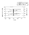
- ⁇ 3 and the normalized microbend loss or the critical fiber diameter were investigated. A part of it is shown in FIG.
- both the normalized microbend loss and the critical fiber diameter tended to decrease linearly as ⁇ 3 decreased. From this, the reduction of ⁇ 3 is effective in reducing the normalized microbend loss and the critical fiber diameter. However, as can be seen from FIG. 5, even if ⁇ 3 has the same value, the normalized microbend loss and the critical fiber diameter differ depending on the structural parameters to be combined, so the combination of structural parameters is selected according to the required specifications and the like. It is preferable to do so.
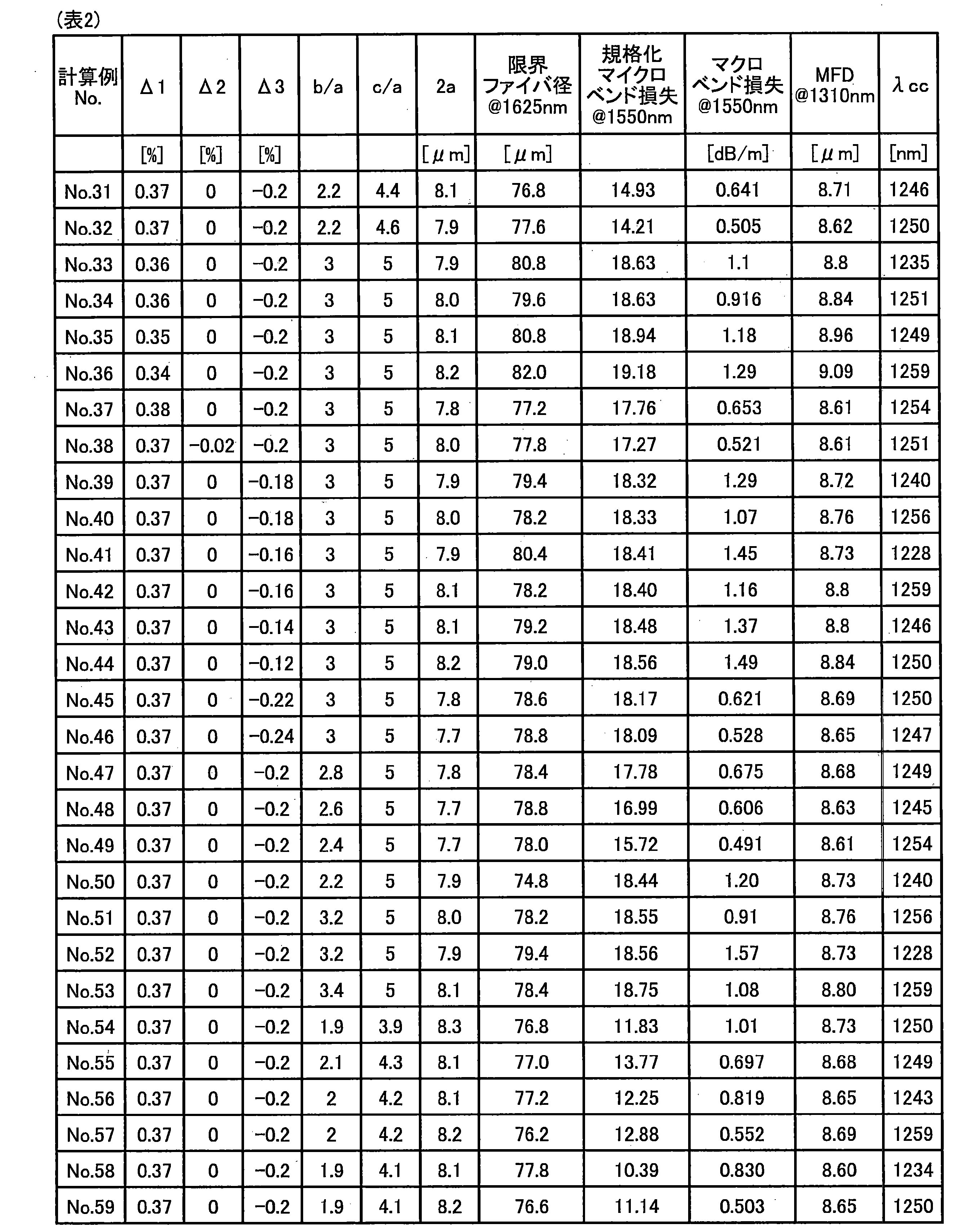
- Tables 1 and 2 show the combinations of the trench-type structural parameters ⁇ 1, ⁇ 2, ⁇ 3, b / a, c / a, and 2a used in the calculation as calculation examples 1 to 59, and the optical fiber in each combination. It shows the characteristics of.
- the unit of macrobend loss is [dB / m].
- [DB / m] and [dB / turn] can be converted assuming that 0.1 dB / turn is approximately equal to 1.59 dB / m.
- the normalized microbend loss is calculated by setting the fiber diameter to 80 ⁇ m, the primary diameter to 129 ⁇ m, and the secondary diameter to 167 ⁇ m, and calculating the normalized microbend loss with respect to the standard SMF. At this time, the primary thickness is 24.5 ⁇ m and the secondary thickness is 19 ⁇ m.
- the limit fiber diameter was 120 ⁇ m or less, further 82 ⁇ m or less, and most of them were 80 ⁇ m or less, so that the leakage loss was 0.001 dB / km.
- the fiber diameter was 120 ⁇ m or less, further 82 ⁇ m or less, and most of them could be 80 ⁇ m or less.
- the MFD at a wavelength of 1310 nm was 8.6 ⁇ m or more and 9.2 ⁇ m or less
- the ⁇ cc was 1000 nm or more and 1260 ⁇ m or less
- the normalized microbend loss at a wavelength of 1550 nm was 20 or less. ..
- the macrobend loss at a wavelength of 1550 nm was 1.59 dB / m or less, that is, 0.1 dB / turn or less.
- the zero dispersion wavelength is 1300 nm or more and 1324 nm or less, and the dispersion slope at the zero dispersion wavelength is 0.092 ps / nm 2 / km. It satisfied the following characteristics.
- Table 3 shows the combinations of the selected W-type structural parameters ⁇ 1, ⁇ 2, b / a, and 2a as calculation example 60, and the characteristics of the optical fiber in each combination.
- the normalized microbend loss is calculated by setting the fiber diameter to 80 ⁇ m, the primary diameter to 135 ⁇ m, and the secondary diameter to 175 ⁇ m, and calculating the normalized microbend loss with respect to the standard SMF.
- the fiber diameter could be 80 ⁇ m or less while the leakage loss was 0.001 dB / km or less.
- the MFD at a wavelength of 1310 nm was 8.6 ⁇ m or more and 9.2 ⁇ m or less
- the ⁇ cc was 1000 nm or more and 1260 ⁇ m or less
- the normalized microbend loss at a wavelength of 1550 nm was 20 or less.
- the macrobend loss at a wavelength of 1550 nm was 1.59 dB / m or less, that is, 0.1 dB / turn or less.
- the zero dispersion wavelength was 1292 nm, and the dispersion slope at the zero dispersion wavelength was 0.092 ps / nm 2 / km.
- the step type, W type, and trench type are exemplified as the refractive index profile, but other refractive index profiles such as the segment core type and the W + side core type can also be applied.
- the present invention is not limited by the above embodiment.
- the present invention also includes a configuration in which the above-mentioned components are appropriately combined. Further, further effects and modifications can be easily derived by those skilled in the art. Therefore, the broader aspect of the present invention is not limited to the above-described embodiment, and various modifications can be made.
- optical fiber according to the present invention can be suitably used for signal transmission.
Landscapes
- Physics & Mathematics (AREA)
- General Physics & Mathematics (AREA)
- Optics & Photonics (AREA)
- Optical Fibers, Optical Fiber Cores, And Optical Fiber Bundles (AREA)
Abstract
細径であるとともに良好な曲げ特性を有する光ファイバを提供することを目的とする。光ファイバは、石英系ガラスからなるコア部と、前記コア部の外周を覆い、前記コア部の最大屈折率よりも低い屈折率を有する石英系ガラスからなるクラッド部と、前記クラッド部の外周を覆うコーティング部と、を備え、前記クラッド部の外径は120μm以下であり、波長1310nmにおけるモードフィールド径が8.6μm以上9.2μm以下であり、実効カットオフ波長が1260μm以下であり、直径20mmで曲げた場合の波長1550nmにおける曲げ損失が0.75dB/turn以下である。
Description
本発明は、光ファイバに関する。
データコムやテレコムの分野において、高密度光ファイバケーブルを実現する光ファイバとして、細径の光ファイバが注目されている。ここで、細径光ファイバとは、主に光ファイバのガラスからなる部分を細径化したものであり、クラッド径が細径のものである。ただし、クラッド径が細径化されたことによって、クラッド部の外周を覆うように形成されたコーティング部を含む外径が細径化されたものも細径光ファイバに含まれる。
従来、細径の光ファイバとして、クラッド部に対するコア部の比屈折率差を高くした構成が開示されている(非特許文献1)。非特許文献1の光ファイバは、比屈折率差を高くしているので、その特性が、ITU-T(国際電気通信連合)G.652で定義される標準的なシングルモード光ファイバの規格(以下、G.652規格)に準拠するものではない。また、細径の光ファイバとして、比屈折率差が-0.08%以上のトレンチ層を設けた構成が開示されている(特許文献1)。特許文献1の光ファイバは、G.652規格に準拠するものであり、そのクラッド径(ファイバ径)は100μm~125μm程度である。また、細径の光ファイバとして、プライマリコート層とセカンダリコート層とをコーティング部として有し、セカンダリコーティング層を25μm以下にした構成が開示されている(特許文献2)。特許文献2の光ファイバは、ファイバ径は125μmであるが、コーティング厚を小さくすることによって細径化を実現している。
また、特許文献3には、有効コア断面積(Aeff)が130μm2以上と比較的大きい光ファイバにて、マイクロベンド損失を抑制する構成が開示されている。特許文献3の光ファイバは、プライマリコーティング層の外径が185μm以上220μm以下であり、セカンダリコーティング層の外径が225μm以上260μm以下である。
また、特許文献4、5には、曲げ特性を考慮したトレンチ型光ファイバの構成が開示されている。
村瀬 他、「細径クラッドファイバの開発」、昭和電線レビュー、vol.53、N0.1(2003)、pp.32-36
G.652規格よりも曲げ特性に対する要求が厳しい、ITU-T G.657で定義されるシングルモード光ファイバの規格(以下、G.657規格)に準拠し、かつ細径の光ファイバについては開示されていなかった。
本発明は、上記に鑑みてなされたものであって、その目的は、細径であるとともに良好な曲げ特性を有する光ファイバを提供することにある。
上述した課題を解決し、目的を達成するために、本発明の一態様に係る光ファイバは、石英系ガラスからなるコア部と、前記コア部の外周を覆い、前記コア部の最大屈折率よりも低い屈折率を有する石英系ガラスからなるクラッド部と、前記クラッド部の外周を覆うコーティング部と、を備え、前記クラッド部の外径は120μm以下であり、波長1310nmにおけるモードフィールド径が8.6μm以上9.2μm以下であり、実効カットオフ波長が1260μm以下であり、直径20mmで曲げた場合の波長1550nmにおける曲げ損失が0.75dB/turn以下である。
本発明の一態様に係る光ファイバにおいて、前記曲げ損失が0.10dB/turn以下でもよい。
本発明の一態様に係る光ファイバにおいて、前記コア部の比屈折率差Δ1が0.3%以上0.5%以下でもよい。
本発明の一態様に係る光ファイバにおいて、零分散波長が1300nm以上1324nm以下あり、前記零分散波長での分散スロープが0.092ps/nm2/km以下でもよい。
本発明の一態様に係る光ファイバにおいて、波長1550nmにおけるマイクロベンド損失が、ITU-T G.652で定義される規格に準拠する特性を有しかつクラッド部の外周に厚さが62.5μmの樹脂コーティング部を有する標準光ファイバの波長1550nmにおけるマイクロベンド損失の20倍以下でもよい。
本発明の一態様に係る光ファイバにおいて、前記マイクロベンド損失は、研磨紙法またはワイヤメッシュ法にて測定した値でもよい。
本発明の一態様に係る光ファイバにおいて、前記コア部は、実効カットオフ波長が1000nm以上1260nm以下になるように設定されていてもよい。
本発明の一態様に係る光ファイバにおいて、前記コア部は、中心コア部と、前記中心コア部の外周に形成された中間層と、前記中間層の外周に形成されたトレンチ層とを有しており、トレンチ型の屈折率プロファイルを有してもよい。
本発明の一態様に係る光ファイバにおいて、前記クラッド部に対する前記トレンチ層の比屈折率差をΔ3とすると、Δ3が-0.26%以上-0.10%以下でもよい。
本発明の一態様に係る光ファイバにおいて、前記クラッド部に対する前記中間層の比屈折率差をΔ2とすると、Δ2が-0.05%以上0.04%以下でもよい。
本発明の一態様に係る光ファイバにおいて、前記中心コア部のコア径を2a、前記トレンチ層の内径を2b、外径を2cとしたときに、b/aが1.8以上3.6以下であり、c/aが3.4以上5.2以下でもよい。
本発明の一態様に係る光ファイバにおいて、前記コア部は、中心コア部と、前記中心コア部の外周に形成されたディプレスト層とを有しており、W型の屈折率プロファイルを有し、前記クラッド部に対する前記ディプレスト層の比屈折率差をΔ2とすると、Δ2が-0.20%以上-0.01%以下であり、前記中心コア部のコア径を2a、前記ディプレスト層の外径を2bとしたときに、b/aが1.5以上6以下でもよい。
本発明の一態様に係る光ファイバにおいて、ステップ型の屈折率プロファイルを有してもよい。
本発明の一態様に係る光ファイバにおいて、前記コーティング部を含む当該光ファイバの外径が210μm以下でもよい。
本発明の一態様に係る光ファイバにおいて、前記コーティング部は、前記クラッド部側に位置するプライマリコーティング層と、前記プライマリコーティング層の外周側に位置するセカンダリコーティング層とを有し、前記プライマリコーティング層の厚さが20μm以上でもよい。
本発明によれば、細径化に適するとともに良好な曲げ特性を有する光ファイバを実現できるという効果を奏する。
以下に、図面を参照しながら、本発明の実施形態を詳細に説明する。なお、以下に説明する実施形態により本発明が限定されるものではない。また、各図面において、同一または対応する構成要素には適宜同一の符号を付している。また、本明細書においては、カットオフ波長または実効カットオフ波長とは、ITU-T G.650.1で定義するケーブルカットオフ波長をいう。また、その他、本明細書で特に定義しない用語についてはG.650.1およびG.650.2における定義、測定方法に従うものとする。
(実施形態)
図1は、実施形態に係る光ファイバの模式的な断面図である。光ファイバ1は、略中心に位置するコア部1aと、コア部1aの外周を覆うクラッド部1bと、クラッド部1bの外周を覆うコーティング部1cとを備えている。
図1は、実施形態に係る光ファイバの模式的な断面図である。光ファイバ1は、略中心に位置するコア部1aと、コア部1aの外周を覆うクラッド部1bと、クラッド部1bの外周を覆うコーティング部1cとを備えている。
コア部1aとクラッド部1bとは、いずれも石英系ガラスからなる。たとえば、コア部1aは、ゲルマニウム(Ge)やフッ素(F)などの屈折率調整用のドーパントが添加された石英ガラスからなる。クラッド部1bは、コア部1aの最大屈折率よりも低い屈折率を有する。クラッド部1bは、たとえば屈折率調整用のドーパントを含まない純石英ガラスからなる。
クラッド部1bの外径(クラッド径)は、120μm以下、好ましくは100μm未満であり、G.652規格に準拠するシングルモード光ファイバのクラッド径である約125μmよりも細径化されている。なお、クラッド径は85μm以下であることが細径化の観点からはより好ましく、82μm以下がさらに好ましい。以下、G.652規格に準拠するシングルモード光ファイバを標準光ファイバとして標準SMFと記載する場合がある。このような標準SMFは、通常はクラッド部の外周に厚さが約62.5μmの樹脂コーティング部を有している。樹脂コーティング部は、たとえば2層構造の場合は、厚さが約37.5μmのプライマリコーティング層と、プライマリコーティング層の外周側に位置し厚さが約25μmのセカンダリコーティング層とからなる。したがって、樹脂コーティング部の外径は約250μmとなる。
光ファイバ1は、たとえば図2A、図2B、および図2Cに示すような屈折率プロファイルを有する。図2A、図2B、および図2Cはいずれも、光ファイバ1のコア部1aの中心軸から半径方向における屈折率プロファイルを示している。
図2Aは、ステップ型の屈折率プロファイルを示している。図2Aにおいて、プロファイルP11がコア部1aの屈折率プロファイルを示し、プロファイルP12がクラッド部1bの屈折率プロファイルを示す。なお、屈折率プロファイルは、クラッド部1bに対する比屈折率差で示している。ステップ型の屈折率プロファイルでは、コア部1aの直径(コア径)は2aであり、クラッド部1bに対するコア部1aの比屈折率差はΔ1である。Δ1はたとえば0.3%以上0.5%以下が好ましく、0.33%以上0.40%以下がより好ましい。
図2Bは、いわゆるW型の屈折率プロファイルを示している。図2Bにおいて、プロファイルP21がコア部1aの屈折率プロファイルを示し、プロファイルP22がクラッド部1bの屈折率プロファイルを示す。W型の屈折率プロファイルでは、コア部1aは、直径が2aの中心コア部と、中心コア部の外周を囲むように形成されており、屈折率がクラッド部の屈折率よりも小さく内径が2aで外径が2bのディプレスト層とで構成されている。クラッド部1bに対する中心コア部の比屈折率差はΔ1である。クラッド部1bに対するディプレスト層の比屈折率差はΔ2である。Δ1はたとえば0.3%以上0.5%以下が好ましい。Δ2はたとえば-0.20%以上-0.01%以下が好ましい。b/aはたとえば1.5以上6以下が好ましい。
図2Cは、いわゆるトレンチ型の屈折率プロファイルを示している。図2Cにおいて、プロファイルP31がコア部1aの屈折率プロファイルを示し、プロファイルP32がクラッド部1bの屈折率プロファイルを示す。トレンチ型の屈折率プロファイルでは、コア部1aは、直径が2aの中心コア部と、中心コア部の外周を囲むように形成されており、屈折率が中心コア部の屈折率よりも小さく内径が2aで外径が2bの中間層と、中間層の外周を囲むように形成されており、屈折率がクラッド部の屈折率よりも小さく内径が2bで外径が2cのトレンチ層とで構成されている。中間層に対する中心コア部の比屈折率差はΔ1である。クラッド部1bに対する中間層の比屈折率差はΔ2である。なお、Δ2は、通常は0%またはその近傍に設定される。クラッド部1bに対するトレンチ層の比屈折率差はΔ3である。
Δ1はたとえば0.3%以上0.5%以下が好ましく、0.33%以上0.40%以下がより好ましい。Δ3はたとえば-0.26%以上-0.10%以下が好ましい。また、たとえばb/aが1.8以上3.6以下であり、c/aが3.4以上5.2以下であることが好ましい。
図1に戻って、コーティング部1cは、たとえば樹脂からなり、光ファイバ1のガラス部分を保護する機能を有する。コーティング部1cは、たとえばUV硬化樹脂等からなり、1層または2層以上の層構造を有する。コーティング部1cが2層構造の場合、コーティング部1cは、クラッド部側に位置するプライマリコーティング層と、プライマリコーティング層の外周側に位置するセカンダリコーティング層とからなる。コーティング部1cに用いられるUV硬化樹脂としては、たとえばウレタンアクリレート系、ポリブタジエンアクリレート系、エポキシアクリレート系、シリコーンアクリレート系、ポリエステルアクリレート系などがあるが、光ファイバのコーティングに使用されるものであれば特に限定されない。
コーティング部1cは、1層構造の場合は、ヤング率が10~800MPaの程度であり、本実施形態では200MPaである。一方、コーティング部1cが2層構造の場合は、プライマリコーティング層のヤング率は0.2~1.5MPaの程度であり、本実施形態では0.5MPaである。セカンダリコーティング層のヤング率は500~2000MPaの程度であり、本実施形態では1000MPaである。
コーティング部1cを含む光ファイバ1の外径は、たとえば210μm以下である。コーティング部1cが2層構造の場合、プライマリコーティング層の厚さは、たとえば20μm以上である。
本実施形態に係る光ファイバ1は、波長1310nmにおけるモードフィールド径(MFD)が8.6μm以上9.2μm以下であり、実効カットオフ波長(λcc)が1260nm以下であり、直径20mmで曲げた場合の波長1550nmにおける曲げ損失(以下、適宜マクロベンド損失と記載する)が0.75dB/turn以下であるという特性を有する。これにより、光ファイバ1は、MFD、λcc、マクロベンド損失について、G.657規格の一種であるG.657A1規格に準拠し、良好な曲げ特性の光ファイバである。
また、光ファイバ1は、零分散波長が1300nm以上1324nm以下あり、零分散波長での分散スロープが0.092ps/nm2/km以下という特性を満たすのが好ましく、分散スロープが0.073ps/nm2/km以上という特性を満たすのがより好ましい。
さらに、光ファイバ1は、クラッド径が120μm以下と、標準SMFのクラッド径である約125μmよりも細径化されている。その結果、光ファイバ1は、細径であるとともに良好な曲げ特性を有する。したがって、光ファイバ1は、高密度光ファイバケーブルを実現するのに適する。
また、マクロベンド損失が0.10dB/turn以下であるという特性を満たせば、G.657規格の一種であり、G.657A1規格よりも曲げ損失対する要求が厳しいG.657A2規格に準拠し、より良好な曲げ特性の光ファイバである。
また、上記実効カットオフを実現するために、実効カットオフ波長が1260nm以下になるようにコア部1aが設定されていることが好ましいが、特に実効カットオフ波長が1260nm以下になるように直径2aが設定されていることが好ましい。また、実効カットオフ波長が1000nm以上になるようにコア部1a、特に直径2aが設定されていれば、マクロベンド損失を低減できるので好ましい。
また、コーティング部1cを含む光ファイバ1の外径が210μm以下であれば、標準SMFの樹脂コーティング部を含む外径である約250μmよりも細径とできる。
ここで、光ファイバにおいて、ガラスからなる部分の外径、たとえばクラッド径を縮小すると、マイクロベンド損失(側圧損失とも呼ばれる)が増大する。通常、光ファイバの伝送損失は、光ファイバケーブルとされた状態では増加する。このときの伝送損失の増加量は、マイクロベンド損失と密接な関係があり、マイクロベンド損失が大きいと増加量も大きい。
本実施形態に係る光ファイバ1において、標準SMFの波長1550nmにおけるマイクロベンド損失の20倍以下のマイクロベンド損失とすれば、実用的な程度のマイクロベンド損失とできる。なお、マイクロベンド損失を標準SMFにおけるマイクロベンド損失で規格化した値を規格化マイクロベンド損失と規定すると、本実施形態に係る光ファイバ1の規格化マイクロベンド損失は20以下が好ましく、さらに10以下が好ましい。マイクロベンド損失の抑制のためには、コーティング部1cが2層構造の場合、プライマリコーティング層の厚さが20μm以上であることが好ましい。
なお、マイクロベンド損失は、JIS C6823:2010_10で規定された固定径ドラム法(研磨紙法の一種)で測定された値や、研磨紙法の一種である伸長ドラム法で測定された値を用いることができる。また、マイクロベンド損失は、ワイヤメッシュ法や、さらにその他の測定方法(たとえば斜め巻付け法)で測定された値でもよい。
また、光ファイバにおいて、ガラスからなる部分の外径、たとえばクラッド径を縮小すると、光ファイバを伝搬する光がガラスからなる部分からリークアウトすることに起因するリーケージ損失が発生する場合がある。そこで、本実施形態に係る光ファイバ1は、波長1625nmにおけるリーケージ損失が0.001dB/km以下とすることが好ましい。
以下、実施形態に係る光ファイバについて、シミュレーション計算の結果を参照して説明する。
まず、図2に示すステップ型、W型、トレンチ型の屈折率プロファイルを有する光ファイバについて、Δ1、Δ2、Δ3、2a、2b、2cなどの構造パラメータを様々な値に網羅的に変化させて組み合わせ、直径20mmで曲げた場合の波長1550nmにおける曲げ損失を計算した。そして、これらの結果から、Δ1と、曲げ損失との関係を調査した。その一部を図3に示す。
図3にもその一部を示すように、いずれの屈折率プロファイルについても、Δ1が0.33%以上0.40%以下の場合に、曲げ損失を0.75dB/turn以下、さらには0.10dB/turn以下とできる場合が多数あることが確認された。
なお、本調査によれば、トレンチ型の屈折率プロファイルを採用すると、曲げ損失を低減しやすいことが確認された。また、Δ1が小さい方が、光ファイバの製造の際に屈折率を高めるドーパントであるGeの使用量を抑制できるので、製造コストを抑制でき、かつ製造し易い。また、W型におけるΔ2の絶対値またはトレンチ型におけるΔ3の絶対値が小さい方が、屈折率を低めるドーパントの使用量を抑制できるので、製造コストを抑制でき、かつ製造し易い。
つづいて、上記調査において、曲げ損失が0.75dB/turn以下とでき、かつ、Δ1が0.33%以上0.40%以下の場合の構造パラメータの組み合わせを選択した。そして、選択した組み合わせについて、コーティング部のプライマリコーティング層の厚さ(以下、適宜プライマリ厚とする)を20μm、セカンダリコーティング層の厚さ(以下、適宜セカンダリ厚とする)を15μmに設定し、標準SMFに対する規格化マイクロベンド損失を計算した。このとき、クラッド径(ファイバ径)を80μm、90μm、100μm、110μm、または120μmに設定した。そして、これらの結果から、Δ1と、規格化マイクロベンド損失との関係を調査した。その一部を図4に示す。
図4にもその一部を示すように、ファイバ径と規格化マイクロベンド損失との間には密接な関係があることが確認された。いずれの屈折率プロファイルについても、またいずれのクラッド径についても、Δ1が0.33%以上0.40%以下の場合に、規格化マイクロベンド損失を20以下とできる場合が多数あることが確認された。また、ファイバ径が100μm、110μmおよび120μmの場合は、規格化マイクロベンド損失を10以下とできる場合が多数あることが確認された。なお、プライマリコーティング層の厚さが20μmという条件は、マイクロベンド損失の低減のためには比較的厳しい条件である。しかしながら、その条件でも、120μm以下の細径のファイバ径において、G.657A1規格またはG.657A2規格のマクロベンド損失だけでなく、規格化マイクロベンド損失が20以下または10以下程度にマイクロベンド損失の増大を抑制できることが確認された。
また、上記計算においては、波長1625nmにおいて0.001dB/km以下のリーケージ損失を得るのに必要な最低限のファイバ径(限界ファイバ径)も計算した。すると、計算した組み合わせにおいては、限界ファイバ径はいずれも100μm以下であり、また多くの組み合わせで80μm以下であった。すなわち、120μm以下の細径のファイバ径、またさらに細径のたとえば80μm程度までのファイバ径においても、過剰なリーケージ損失が発生しないことが確認された。
なお、コーティング部を含む光ファイバの外径については、クラッド径を120μm以下とすれば、プライマリ厚を25μm以下、セカンダリ厚を20μm以下とすることで、210μm以下とできる。また、当該光ファイバの外径をさらに小さくするには、クラッド径をさらに小さくするとともに、プライマリ厚やセカンダリ厚を小さくすることが好まし。たとえば、上記計算に基づき、クラッド径を80μm程度とし、プライマリ厚を25μm以下、セカンダリ厚を20μm以下とすることで、当該光ファイバの外径を170μm以下とできる。
つづいて、上記調査において、ステップ型、W型、トレンチ型の屈折率プロファイルのうち、トレンチ型であり、かつ、Δ1が0.33%以上0.40%以下の場合の構造パラメータの組み合わせを選択した。そして、選択した組み合わせについて、クラッド径を80μm、プライマリコーティング層の外径(以下、適宜プライマリ径とする)を129μm、セカンダリコーティング層の外径(以下、適宜セカンダリ径とする)を167μmに設定し、Δ3と、規格化マイクロベンド損失または限界ファイバ径との関係を調査した。その一部を図5に示す。
図5にもその一部を示すように、Δ3の減少に応じて、規格化マイクロベンド損失および限界ファイバ径のいずれも直線状に減少する傾向がみられた。このことからΔ3の低減は規格化マイクロベンド損失および限界ファイバ径の低減の上で効果的である。ただし、図5からも解るように、Δ3が同じ値であっても、組み合わせる構造パラメータに応じて規格化マイクロベンド損失および限界ファイバ径は異なるので、要求仕様等に応じて構造パラメータの組み合わせを選択するのが好ましい。
表1、2は、計算例1~59として、計算に用いたトレンチ型の構造パラメータであるΔ1、Δ2、Δ3、b/a、c/a、2aの組み合わせと、各組み合わせの場合の光ファイバの特性について示している。なお、マクロベンド損失については、単位を[dB/m]で示している。[dB/m]と[dB/turn]とは、0.1dB/turnがほぼ1.59dB/mと等しいとして換算できる。また、規格化マイクロベンド損失は、ファイバ径を80μm、プライマリ径を129μm、セカンダリ径を167μmに設定し、標準SMFに対する規格化マイクロベンド損失を計算したものである。このとき、プライマリ厚は24.5μmであり、セカンダリ厚は19μmである。
表1、2に示すように、計算例1~59のいずれも、限界ファイバ径が120μm以下、さらには82μm以下であり、また殆どが80μm以下であったので、リーケージ損失を0.001dB/km以下としながらファイバ径を120μm以下、さらには82μm以下であり、また殆どが80μm以下とできるものであった。また、計算例1~59のいずれも、波長1310nmにおけるMFDが8.6μm以上9.2μm以下であり、λccが1000nm以上1260μm以下であり、波長1550nmにおける規格化マイクロベンド損失が20以下であった。また、計算例1~59のいずれも、波長1550nmにおけるマクロベンド損失が1.59dB/m以下、すなわち0.1dB/turn以下であった。また、表1と表2とに記載の計算例1~59の光ファイバはいずれも、零分散波長が1300nm以上1324nm以下であり、零分散波長での分散スロープが0.092ps/nm2/km以下という特性を満たしていた。
つづいて、上記調査におけるW型の構造パラメータの組み合わせを選択した。表3は、計算例60として、選択したW型の構造パラメータであるΔ1、Δ2、b/a、2aの組み合わせと、各組み合わせの場合の光ファイバの特性について示している。なお、規格化マイクロベンド損失は、ファイバ径を80μm、プライマリ径を135μm、セカンダリ径を175μmに設定し、標準SMFに対する規格化マイクロベンド損失を計算したものである。
表3に示すように、計算例60では、限界ファイバ径が80μm以下であったので、リーケージ損失を0.001dB/km以下としながらファイバ径を80μm以下とできるものであった。また、波長1310nmにおけるMFDが8.6μm以上9.2μm以下であり、λccが1000nm以上1260μm以下であり、波長1550nmにおける規格化マイクロベンド損失が20以下であった。また、波長1550nmにおけるマクロベンド損失が1.59dB/m以下、すなわち0.1dB/turn以下であった。なお、零分散波長は1292nmであり、零分散波長での分散スロープは0.092ps/nm2/kmであった。
すなわち、計算例1~60によれば、G.657A1規格やG.657A2規格に相当するMFD、λcc、マクロベンド損失と、120μm以下のファイバ径を実現できるので、細径であるとともに良好な曲げ特性を有する光ファイバを実現できる。なお、規格化マイクロベンド損失については、ファイバ径やプライマリ径やセカンダリ径を上記の設定した値よりも大きく設定すれば、マイクロベンド損失をさらに低減し、規格化マイクロベンド損失を10以下にすることは容易に可能である。


なお、上記実施形態では、屈折率プロファイルとしてステップ型、W型、トレンチ型を例示しているが、セグメントコア型やW+サイドコア型などのその他の屈折率プロファイルについても適用できる。
また、上記実施形態により本発明が限定されるものではない。上述した各構成要素を適宜組み合わせて構成したものも本発明に含まれる。また、さらなる効果や変形例は、当業者によって容易に導き出すことができる。よって、本発明のより広範な態様は、上記の実施形態に限定されるものではなく、様々な変更が可能である。
本発明に係る光ファイバは、信号伝送に好適に利用できる。
1 光ファイバ
1a コア部
1b クラッド部
1c コーティング部
P11、P12、P21、P22、P31、P32 プロファイル
1a コア部
1b クラッド部
1c コーティング部
P11、P12、P21、P22、P31、P32 プロファイル
Claims (15)
- 石英系ガラスからなるコア部と、
前記コア部の外周を覆い、前記コア部の最大屈折率よりも低い屈折率を有する石英系ガラスからなるクラッド部と、
前記クラッド部の外周を覆うコーティング部と、
を備え、
前記クラッド部の外径は120μm以下であり、
波長1310nmにおけるモードフィールド径が8.6μm以上9.2μm以下であり、
実効カットオフ波長が1260μm以下であり、
直径20mmで曲げた場合の波長1550nmにおける曲げ損失が0.75dB/turn以下であることを特徴とする光ファイバ。 - 前記曲げ損失が0.10dB/turn以下であることを特徴とする請求項1に記載の光ファイバ。
- 前記コア部の比屈折率差Δ1が0.3%以上0.5%以下であることを特徴とする請求項1または2に記載の光ファイバ。
- 零分散波長が1300nm以上1324nm以下あり、前記零分散波長での分散スロープが0.092ps/nm2/km以下であることを特徴とする請求項1~3のいずれか一つに記載の光ファイバ。
- 波長1550nmにおけるマイクロベンド損失が、ITU-T G.652で定義される規格に準拠する特性を有しかつクラッド部の外周に厚さが62.5μmの樹脂コーティング部を有する標準光ファイバの波長1550nmにおけるマイクロベンド損失の20倍以下であることを特徴とする請求項1~4のいずれか一つに記載の光ファイバ。
- 前記マイクロベンド損失は、研磨紙法またはワイヤメッシュ法にて測定した値であることを特徴とする請求項5に記載の光ファイバ。
- 前記コア部は、実効カットオフ波長が1000nm以上1260nm以下になるように設定されていることを特徴とする請求項1~6のいずれか一つに記載の光ファイバ。
- 前記コア部は、中心コア部と、前記中心コア部の外周に形成された中間層と、前記中間層の外周に形成されたトレンチ層とを有しており、
トレンチ型の屈折率プロファイルを有することを特徴とする請求項1~7のいずれか一つに記載の光ファイバ。 - 前記クラッド部に対する前記トレンチ層の比屈折率差をΔ3とすると、Δ3が-0.26%以上-0.10%以下であることを特徴とする請求項8に記載の光ファイバ。
- 前記クラッド部に対する前記中間層の比屈折率差をΔ2とすると、Δ2が-0.05%以上0.04%以下であることを特徴とする請求項8または9に記載の光ファイバ。
- 前記中心コア部のコア径を2a、前記トレンチ層の内径を2b、外径を2cとしたときに、b/aが1.8以上3.6以下であり、c/aが3.4以上5.2以下であることを特徴とする請求項8~10のいずれか一つに記載の光ファイバ。
- 前記コア部は、中心コア部と、前記中心コア部の外周に形成されたディプレスト層とを有しており、
W型の屈折率プロファイルを有し、
前記クラッド部に対する前記ディプレスト層の比屈折率差をΔ2とすると、Δ2が-0.20%以上-0.01%以下であり、
前記中心コア部のコア径を2a、前記ディプレスト層の外径を2bとしたときに、b/aが1.5以上6以下であることを特徴とする請求項1~7のいずれか一つに記載の光ファイバ。 - ステップ型の屈折率プロファイルを有することを特徴とする請求項1~7のいずれか一つに記載の光ファイバ。
- 前記コーティング部を含む当該光ファイバの外径が210μm以下であることを特徴とする請求項1~13のいずれか一つに記載の光ファイバ。
- 前記コーティング部は、前記クラッド部側に位置するプライマリコーティング層と、前記プライマリコーティング層の外周側に位置するセカンダリコーティング層とを有し、前記プライマリコーティング層の厚さが20μm以上であることを特徴とする請求項1~14のいずれか一つに記載の光ファイバ。
Priority Applications (2)
| Application Number | Priority Date | Filing Date | Title |
|---|---|---|---|
| EP20815268.6A EP3978968B1 (en) | 2019-05-27 | 2020-05-22 | Optical fiber |
| US17/456,601 US11860407B2 (en) | 2019-05-27 | 2021-11-26 | Optical fiber |
Applications Claiming Priority (2)
| Application Number | Priority Date | Filing Date | Title |
|---|---|---|---|
| JP2019-098406 | 2019-05-27 | ||
| JP2019098406A JP7145814B2 (ja) | 2019-05-27 | 2019-05-27 | 光ファイバ |
Related Child Applications (1)
| Application Number | Title | Priority Date | Filing Date |
|---|---|---|---|
| US17/456,601 Continuation US11860407B2 (en) | 2019-05-27 | 2021-11-26 | Optical fiber |
Publications (1)
| Publication Number | Publication Date |
|---|---|
| WO2020241531A1 true WO2020241531A1 (ja) | 2020-12-03 |
Family
ID=73548242
Family Applications (1)
| Application Number | Title | Priority Date | Filing Date |
|---|---|---|---|
| PCT/JP2020/020423 Ceased WO2020241531A1 (ja) | 2019-05-27 | 2020-05-22 | 光ファイバ |
Country Status (4)
| Country | Link |
|---|---|
| US (1) | US11860407B2 (ja) |
| EP (1) | EP3978968B1 (ja) |
| JP (1) | JP7145814B2 (ja) |
| WO (1) | WO2020241531A1 (ja) |
Cited By (1)
| Publication number | Priority date | Publication date | Assignee | Title |
|---|---|---|---|---|
| US12474522B2 (en) | 2022-04-25 | 2025-11-18 | Corning Incorporated | Compliant optical fiber |
Families Citing this family (3)
| Publication number | Priority date | Publication date | Assignee | Title |
|---|---|---|---|---|
| JPWO2022215603A1 (ja) * | 2021-04-08 | 2022-10-13 | ||
| CN115542455B (zh) * | 2022-09-27 | 2025-09-09 | 武汉光芯光电技术有限公司 | 一种兼容g652d标准的大模场g657a2光纤 |
| US12353002B2 (en) * | 2022-12-22 | 2025-07-08 | Sterlite Technologies Limited | Optical fiber with improved microbending performance |
Citations (10)
| Publication number | Priority date | Publication date | Assignee | Title |
|---|---|---|---|---|
| JPH0519144A (ja) | 1991-07-11 | 1993-01-29 | Fujikura Ltd | 光フアイバ |
| JP2007033466A (ja) * | 2004-08-11 | 2007-02-08 | Furukawa Electric Co Ltd:The | 光ファイバ、光ファイバテープおよび光インターコネクションシステム |
| JP2010181641A (ja) | 2009-02-05 | 2010-08-19 | Fujikura Ltd | 光ファイバ |
| US20110058780A1 (en) * | 2009-06-26 | 2011-03-10 | Qingrong Han | Single-mode fiber and production method thereof |
| JP2013242545A (ja) | 2012-04-26 | 2013-12-05 | Shin Etsu Chem Co Ltd | 光ファイバ |
| JP2014010412A (ja) * | 2012-07-03 | 2014-01-20 | Hitachi Cable Ltd | シングルモード光ファイバ |
| JP2015219271A (ja) | 2014-05-14 | 2015-12-07 | 住友電気工業株式会社 | 光ファイバ |
| JP2016522428A (ja) * | 2013-04-15 | 2016-07-28 | コーニング インコーポレイテッド | 小さい直径の光ファイバ |
| EP3098631A1 (en) * | 2014-01-26 | 2016-11-30 | Fiberhome Telecommunication Technologies Co. Ltd | Small bending radius single-mode optical fiber with compatibility |
| WO2016190297A1 (ja) | 2015-05-27 | 2016-12-01 | 株式会社フジクラ | 光ファイバ |
Family Cites Families (1)
| Publication number | Priority date | Publication date | Assignee | Title |
|---|---|---|---|---|
| US9989699B2 (en) * | 2016-10-27 | 2018-06-05 | Corning Incorporated | Low bend loss single mode optical fiber |
-
2019
- 2019-05-27 JP JP2019098406A patent/JP7145814B2/ja active Active
-
2020
- 2020-05-22 EP EP20815268.6A patent/EP3978968B1/en active Active
- 2020-05-22 WO PCT/JP2020/020423 patent/WO2020241531A1/ja not_active Ceased
-
2021
- 2021-11-26 US US17/456,601 patent/US11860407B2/en active Active
Patent Citations (10)
| Publication number | Priority date | Publication date | Assignee | Title |
|---|---|---|---|---|
| JPH0519144A (ja) | 1991-07-11 | 1993-01-29 | Fujikura Ltd | 光フアイバ |
| JP2007033466A (ja) * | 2004-08-11 | 2007-02-08 | Furukawa Electric Co Ltd:The | 光ファイバ、光ファイバテープおよび光インターコネクションシステム |
| JP2010181641A (ja) | 2009-02-05 | 2010-08-19 | Fujikura Ltd | 光ファイバ |
| US20110058780A1 (en) * | 2009-06-26 | 2011-03-10 | Qingrong Han | Single-mode fiber and production method thereof |
| JP2013242545A (ja) | 2012-04-26 | 2013-12-05 | Shin Etsu Chem Co Ltd | 光ファイバ |
| JP2014010412A (ja) * | 2012-07-03 | 2014-01-20 | Hitachi Cable Ltd | シングルモード光ファイバ |
| JP2016522428A (ja) * | 2013-04-15 | 2016-07-28 | コーニング インコーポレイテッド | 小さい直径の光ファイバ |
| EP3098631A1 (en) * | 2014-01-26 | 2016-11-30 | Fiberhome Telecommunication Technologies Co. Ltd | Small bending radius single-mode optical fiber with compatibility |
| JP2015219271A (ja) | 2014-05-14 | 2015-12-07 | 住友電気工業株式会社 | 光ファイバ |
| WO2016190297A1 (ja) | 2015-05-27 | 2016-12-01 | 株式会社フジクラ | 光ファイバ |
Non-Patent Citations (2)
| Title |
|---|
| MURASE: "Development of Cladding Fiber with Small Diameter", vol. 53, 2003, SWCC SHOWA HOLDINGS CO.,LTD., pages: 32 - 36 |
| See also references of EP3978968A4 |
Cited By (1)
| Publication number | Priority date | Publication date | Assignee | Title |
|---|---|---|---|---|
| US12474522B2 (en) | 2022-04-25 | 2025-11-18 | Corning Incorporated | Compliant optical fiber |
Also Published As
| Publication number | Publication date |
|---|---|
| EP3978968A1 (en) | 2022-04-06 |
| EP3978968B1 (en) | 2025-11-12 |
| US11860407B2 (en) | 2024-01-02 |
| US20220082753A1 (en) | 2022-03-17 |
| EP3978968A4 (en) | 2023-05-31 |
| JP2020194033A (ja) | 2020-12-03 |
| JP7145814B2 (ja) | 2022-10-03 |
Similar Documents
| Publication | Publication Date | Title |
|---|---|---|
| JP7608343B2 (ja) | 光ファイバ | |
| US11719879B2 (en) | Optical fiber | |
| CN101006372B (zh) | 单模光纤 | |
| WO2020241531A1 (ja) | 光ファイバ | |
| US9188736B2 (en) | Low bend loss optical fiber | |
| US12072526B2 (en) | Optical fiber | |
| CN104834054A (zh) | 光纤 | |
| CN106662705B (zh) | 光纤 | |
| CN117136321A (zh) | 光纤 | |
| KR20180124729A (ko) | 광파이버 | |
| US11624871B2 (en) | Optical fiber | |
| WO2012128250A1 (ja) | 光ファイバ、光ファイバコードおよび光ファイバケーブル | |
| CN106662704A (zh) | 光纤及光纤传输路径 | |
| WO2023085134A1 (ja) | 光ファイバ | |
| JP7793379B2 (ja) | 光ファイバ | |
| CN102132176A (zh) | 单模光纤 | |
| WO2024257700A1 (ja) | マルチコアファイバ | |
| WO2026079384A1 (ja) | 光ファイバケーブル |
Legal Events
| Date | Code | Title | Description |
|---|---|---|---|
| 121 | Ep: the epo has been informed by wipo that ep was designated in this application |
Ref document number: 20815268 Country of ref document: EP Kind code of ref document: A1 |
|
| NENP | Non-entry into the national phase |
Ref country code: DE |
|
| ENP | Entry into the national phase |
Ref document number: 2020815268 Country of ref document: EP Effective date: 20220103 |
|
| WWG | Wipo information: grant in national office |
Ref document number: 2020815268 Country of ref document: EP |