WO2024257700A1 - マルチコアファイバ - Google Patents
マルチコアファイバ Download PDFInfo
- Publication number
- WO2024257700A1 WO2024257700A1 PCT/JP2024/020843 JP2024020843W WO2024257700A1 WO 2024257700 A1 WO2024257700 A1 WO 2024257700A1 JP 2024020843 W JP2024020843 W JP 2024020843W WO 2024257700 A1 WO2024257700 A1 WO 2024257700A1
- Authority
- WO
- WIPO (PCT)
- Prior art keywords
- core
- cladding
- less
- trench
- diameter
- Prior art date
- Legal status (The legal status is an assumption and is not a legal conclusion. Google has not performed a legal analysis and makes no representation as to the accuracy of the status listed.)
- Ceased
Links
Images





Classifications
-
- G—PHYSICS
- G02—OPTICS
- G02B—OPTICAL ELEMENTS, SYSTEMS OR APPARATUS
- G02B6/00—Light guides; Structural details of arrangements comprising light guides and other optical elements, e.g. couplings
- G02B6/02—Optical fibres with cladding with or without a coating
-
- G—PHYSICS
- G02—OPTICS
- G02B—OPTICAL ELEMENTS, SYSTEMS OR APPARATUS
- G02B6/00—Light guides; Structural details of arrangements comprising light guides and other optical elements, e.g. couplings
- G02B6/02—Optical fibres with cladding with or without a coating
- G02B6/036—Optical fibres with cladding with or without a coating core or cladding comprising multiple layers
Definitions
- the present invention relates to a multicore fiber.
- Multicore fibers in which multiple cores are surrounded by a single cladding, are sometimes used. Multicore fibers can transmit multiple signals using light propagating through each of the multiple cores, increasing the transmission capacity per optical fiber.
- Patent Document 1 describes a multicore fiber in which four core elements are arranged.
- the core element includes a core and a trench portion that surrounds the outer peripheral surface of the core and has a lower refractive index than the cladding.
- this trench portion is called the first cladding region
- the cladding is called the second cladding region.
- the cladding has a diameter of 125 ⁇ m, and crosstalk of -54 dB/km is achieved.
- the cladding diameter of the multicore fiber in Patent Document 1 is 125 ⁇ m.
- the cladding diameter is reduced, the distance between the core and the outer peripheral surface of the cladding becomes smaller, which is likely to increase the confinement loss, and there is also a concern that the inter-core distance becomes smaller, which is likely to increase the crosstalk.
- the present invention aims to provide a multicore fiber that can reduce the cladding diameter while suppressing crosstalk and confinement loss.
- a first aspect of the present invention for solving the above problems is a multi-core fiber comprising: two to four core elements including a core and a trench layer surrounding an outer peripheral surface of the core; and a cladding surrounding the outer peripheral surface of each of the core elements without any gaps, wherein each of the core elements is arranged on a circumference centered on the center of the cladding, the diameter of the core element is not more than 1 ⁇ m smaller than the inter-core distance between the core element and the shortest adjacent core element, the mode field diameter of light having a wavelength of 1.31 ⁇ m propagating through the core is 8.8 ⁇ m or less, and a trench volume, which is the product of the cross-sectional area of the trench layer in a cross section perpendicular to the longitudinal direction of the cladding and the absolute value of the relative refractive index difference of the trench layer with respect to the cladding, is 105 ⁇ m2 % or more and 350 ⁇ m2 % or less.
- the cladding diameter can be 104 ⁇ m or less when there are four core elements, and the cladding diameter can be 90 ⁇ m or less when there are two core elements. In this way, with the multicore fiber of the present invention, crosstalk and confinement loss can be suppressed while the cladding diameter is reduced.
- a second aspect of the present invention is the multi-core fiber according to the first aspect, wherein the trench volume is 135 ⁇ m 2 % or more.
- the confinement loss can be further reduced to 0.001 dB/km or less even if the cladding thickness is approximately 25.3 ⁇ m.
- a third aspect of the present invention is the multi-core fiber according to the first aspect, characterized in that the trench volume is 190 ⁇ m 2 % or more.
- the confinement loss can be kept to 0.01 dB/km or less even if the cladding thickness is approximately 21.7 ⁇ m.
- a fourth aspect of the present invention is the multi-core fiber according to the first aspect, wherein the trench volume is 215 ⁇ m 2 % or more.
- the confinement loss can be kept below 0.001 dB/km even with a cladding thickness of approximately 21.7 ⁇ m.
- a fifth aspect of the present invention is the multi-core fiber according to the first aspect, wherein the trench volume is 234 ⁇ m 2 % or more.
- a sixth aspect of the present invention is the multi-core fiber according to the first aspect, wherein the trench volume is 269 ⁇ m 2 % or more.
- the confinement loss when propagating light with a wavelength of 1.625 ⁇ m, the confinement loss can be kept to 0.01 dB/km or less even with a cladding thickness of approximately 21.7 ⁇ m.
- a seventh aspect of the present invention is the multi-core fiber according to the first aspect, wherein the trench volume is 306 ⁇ m 2 % or more.
- the confinement loss can be kept to 0.001 dB/km or less even with a cladding thickness of approximately 21.7 ⁇ m.
- the core distance can be set to about 35 ⁇ m and the clad thickness can be set to approximately 21.7 ⁇ m, so that when there are four core elements, the clad diameter can be set to 93 ⁇ m or less, and when there are two core elements, the clad diameter can be set to 80 ⁇ m or less.
- the present invention provides a multicore fiber that can reduce the cladding diameter while suppressing crosstalk and confinement loss.
- FIG. 1 is a diagram showing a cross section perpendicular to the longitudinal direction of a multicore fiber according to an embodiment of the present invention.
- FIG. 2 is a diagram showing the refractive index profile of the core element of FIG. 1 .
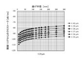
- FIG. 13 is a diagram showing the relationship between the bending radius and the magnitude of crosstalk when light with a wavelength of 1.31 ⁇ m is propagated.
- FIG. 11 is a diagram showing the relationship between the bending radius and the magnitude of crosstalk when light with a wavelength of 1.625 ⁇ m is propagated.
- FIG. 13 is a diagram showing the relationship between cladding thickness and the magnitude of confinement loss.
- FIG. 1 is a diagram showing the relationship between wavelength and confinement loss.
- FIG. 13 is a diagram showing the relationship between the trench volume and the inter-core distance when light with a wavelength of 1.31 ⁇ m is propagated.
- FIG. 13 is a diagram showing the relationship between the trench volume and the inter-core distance when light with a wavelength of 1.625 ⁇ m is propagated.
- FIG. 13 is a diagram showing the relationship between trench volume and cladding thickness when light with a wavelength of 1.31 ⁇ m is propagated.
- FIG. 13 is a diagram showing the relationship between trench volume and cladding thickness when light with a wavelength of 1.625 ⁇ m is propagated.
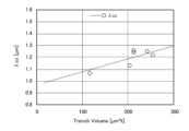
- FIG. 13 is a diagram showing the relationship between trench volume and 22 m cable cutoff wavelength.
- FIG. 2 illustrates a multicore fiber with two core elements.
- FIG. 1 is a diagram showing a cross section perpendicular to the longitudinal direction of a multicore fiber according to this embodiment.
- the multicore fiber 1 of this embodiment comprises four core elements 10, a cladding 20 that tightly surrounds the outer circumferential surface of each of the core elements 10, and a coating layer 30 that covers the outer circumferential surface of the cladding 20.
- the cladding 20 is also called a common cladding because it surrounds the outer circumferential surface of each of the core elements 10.
- Each core element 10 includes a core 11, an outer core 12 that tightly surrounds the outer circumferential surface of the core 11, and a trench layer 13 that tightly surrounds the outer circumferential surface of the outer core 12.
- the cores 11 are positioned at equal intervals on the same circumference CR centered on the center C of the cladding 20.
- the diameter of the core 11 is, for example, 5.5 ⁇ m or more and 8.8 ⁇ m or less.
- the outer diameter of the outer core 12, i.e., the inner diameter of the trench layer 13, is 12 ⁇ m or more and 25 ⁇ m or less.
- the outer diameter of the trench layer 13, i.e., the diameter of the core element 10, is 1 ⁇ m smaller than the core-to-core distance between the core element 10 and the other core element 10 adjacent to it at the shortest distance, for example, 24 ⁇ m or more and 40 ⁇ m or less.
- the outer diameter of the trench layer 13 may be indicated as Dtrench as shown in FIG.
- the center-to-center distance between the adjacent cores 11 may be indicated as ⁇ , in which case the center-to-center distance between the cores 11 located diagonally is 2 1/2 ⁇ .
- the distance between the center of the core 11 and the outer peripheral surface of the cladding 20 may be referred to as the cladding thickness, and the cladding thickness may be indicated as OCT.
- the distance from the center of the cladding 20 to the center of the core 11 may be indicated as R1.
- the diameter of the cladding 20 may be indicated as Dclad.
- the diameter Dclad of the cladding 20 in this embodiment can be expressed by the following formula (1).
- Dclad 2 1/2 ⁇ +2OCT (1)
- the refractive index of the core 11 is higher than those of the outer core 12 and the cladding 20, and the relative refractive index difference of the core 11 with respect to the cladding 20 is 0.2% or more and 0.9% or less.
- the refractive index of the trench layer 13 is lower than those of the outer core 12 and the cladding 20.
- the relative refractive index difference of the trench layer 13 with respect to the cladding 20 is -0.9% or more and -0.1% or less.
- the refractive index of the outer core 12 may be the same as that of the cladding 20, or may be higher or lower than that of the cladding 20.
- the relative refractive index difference of the outer core 12 with respect to the cladding 20 is -0.3% or more and 0.3% or less.
- the relative refractive index difference of the core 11 with respect to the cladding 20 may be indicated as ⁇ 1
- the relative refractive index difference of the outer core 12 with respect to the cladding 20 may be indicated as ⁇ 2
- the relative refractive index difference of the trench layer 13 with respect to the cladding 20 may be indicated as ⁇ 3.
- the core 11 is made of silica glass doped with a dopant such as germanium that increases the refractive index.
- the cladding 20 is made of silica glass doped with no dopant.
- the trench layer 13 is made of silica glass doped with a dopant such as fluorine that decreases the refractive index.
- the outer core 12 may be doped with a dopant that increases the refractive index, a dopant that decreases the refractive index, or no dopant at all, depending on its relationship with the refractive index of the cladding 20. Note that whether or not dopants are added to the core 11, outer core 12, trench layer 13, and cladding 20, and if so, the type of dopant, are not limited to the above.
- the trench volume is defined as the product of the cross-sectional area of the trench layer 13 in a cross section perpendicular to the longitudinal direction of the cladding 20 and the absolute value of the relative refractive index difference of the trench layer 13 with respect to the cladding 20.
- the trench volume may be indicated as TV.
- the cross-sectional area of the trench layer 13 is (r3 2 - r2 2 ) ⁇ ⁇ . Therefore, the trench volume TV can be expressed by the following formula (2).
- TV (r3 2 - r2 2 ) ⁇
- the distance R1 from the center of the cladding 20 to the center of the core 11 is equal to or greater than the cladding thickness OCT, i.e., OCT/R1 ⁇ 1. In this case, it is easier to position the marker closer to the center C of the cladding than the core element 10, and fiber curl can be suppressed.
- the coating layer 30 includes an inner coating layer 31 that coats the outer peripheral surface of the cladding 20, and an outer coating layer 32 that coats the outer peripheral surface of the inner coating layer 31.
- the inner coating layer 31 and the outer coating layer 32 are each made of a resin such as an ultraviolet-curable resin, and the inner coating layer 31 and the outer coating layer 32 are made of different resins.
- FIG. 2 is a diagram showing a predetermined refractive index distribution of the core element 10 of the multi-core fiber 1 of FIG. 1.
- the same symbols are written at positions indicating the relative refractive index difference of the core 11, the outer core 12, the trench layer 13, and the clad 20.
- the relative refractive index difference ⁇ 2 of the outer core 12 with respect to the clad 20 is 0.01%.
- the relative refractive index difference ⁇ 1 of the core 11 with respect to the clad 20 is 0.35%.
- the relative refractive index difference ⁇ 3 of the trench layer 13 with respect to the clad 20 is ⁇ 0.4%.
- the diameter 2 ⁇ r1 of the core 11 is 7 ⁇ m
- the outer diameter 2 ⁇ r2 of the outer core 12 is 16 ⁇ m
- the outer diameter 2 ⁇ r3 of the trench layer 13, which is the diameter of the core element 10 is 32 ⁇ m.
- the trench volume TV is approximately 234 ⁇ m 2 %.
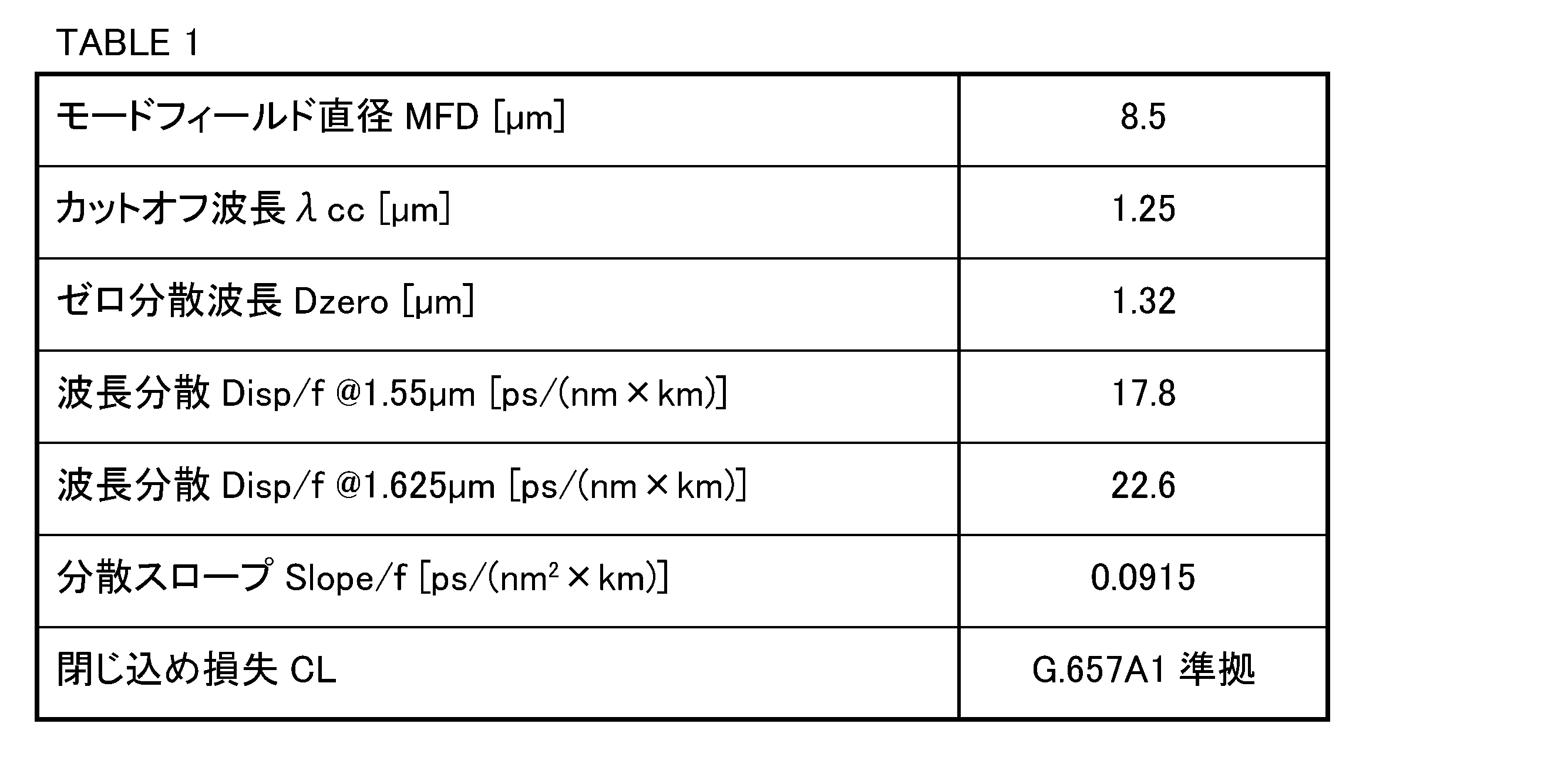
- the optical characteristics of the core element 10 are as shown in Table 1 below.
- FIG. 3 is a diagram showing the relationship between the bending radius of the multicore fiber 1 and the crosstalk XT from one adjacent core when light with a wavelength of 1.31 ⁇ m is propagated.
- the crosstalk XT from one adjacent core is smaller than ⁇ 75 dB/km at most when the bending radius of the multicore fiber 1 is 300 mm. Note that when light with a wavelength of 1.31 ⁇ m is propagated in the multicore fiber 1, sufficient optical communication quality is maintained if the amount of crosstalk from one adjacent core is ⁇ 35 dB/km or less.
- Figure 4 is a diagram showing the relationship between the bending radius of the multicore fiber 1 and the crosstalk XT from one adjacent core when light with a wavelength of 1.625 ⁇ m is propagated.
- the crosstalk XT from one adjacent core is smaller than -36 dB/km at most when the bending radius of the multicore fiber 1 is 300 mm. Note that when light with a wavelength of 1.625 ⁇ m is propagated in the multicore fiber 1, sufficient optical communication quality is maintained if the amount of crosstalk between adjacent cores is -30 dB/km or less.
- the inter-core distance ⁇ is 33 ⁇ m or more. In this explanation, we have considered the case where the inter-core distance ⁇ is 35 ⁇ m or more.
- FIG. 5 is a diagram showing the relationship between the cladding thickness OCT and the magnitude of the confinement loss CL.
- the core element 10 is arranged in a single-core fiber having a cladding diameter of 100 ⁇ m and an outer diameter including the coating layer of 160 ⁇ m, and the confinement loss CL is obtained by simulation by changing the position of the core element 10 from the center to the outer periphery of the cladding.
- the bending radius of the optical fiber at this time is 76 mm.
- the bending radius of the optical fiber of 76 mm is the radius of a general bobbin, and is smaller than the bending radius in an optical fiber cable.
- the cladding thickness OCT needs to be 21.5 ⁇ m or more. This condition is also the same for the multi-core fiber 1.
- the confinement loss CL is 0.001 dB/km or less.
- the confinement loss CL In the case of propagating light having a wavelength of 1.31 ⁇ m, if the cladding thickness OCT is 17.5 ⁇ m or more, the confinement loss CL is 0.001 dB/km or less. The magnitude of this confinement loss CL is two orders of magnitude lower than the light loss generally required in optical communications. Therefore, if the confinement loss CL is 0.001 dB/km or less, it is a sufficiently small loss in optical communications. In addition, when light having a wavelength of 1.625 ⁇ m is propagated through the multicore fiber 1, if the confinement loss CL is 0.01 dB/km or less, sufficient quality of optical communications is maintained.
- Figure 6 shows the relationship between wavelength and confinement loss.
- Figure 6 shows cases where the bending radius R is 76 mm, 10 mm, and 7.5 mm. Note that in Figure 6, the simulation is performed using a multicore fiber 1 in which the core element 10 has the refractive index distribution shown in Figure 2, the core distance ⁇ is 40 ⁇ m, the cladding thickness OCT is 21.7 ⁇ m, the diameter of the cladding 20 is 100 ⁇ m, and the outer diameter of the coating layer 30 is 160 ⁇ m.
- the confinement loss is about 0.75 dB/km.
- the confinement loss when light of a wavelength of 1.625 ⁇ m is propagated through an optical fiber with a bending radius of 7.5 mm is 1.0 dB/turn or less. Therefore, the confinement loss shown in Figure 6 is about 0.75 dB/km when light of a wavelength of 1.625 ⁇ m is propagated through an optical fiber with a bending radius of 7.5 mm. 657 Fully meets A2.
- the inter-core distance ⁇ can be set to 35 ⁇ m, and the clad thickness OCT can be set to 21.5 ⁇ m.
- Dclad is approximately 92.5 ⁇ m. Therefore, in the case of a core having the refractive index distribution of FIG. 2, a multi-core fiber having the crosstalk and confinement loss characteristics required by the market and a clad 20 diameter of 95 ⁇ m or less can be realized. Note that in the case of a core element having the refractive index distribution of FIG.
- Dclad is approximately 99.97 ⁇ m. Therefore, in the case of a core having the refractive index distribution of FIG. 2, by setting the inter-core distance ⁇ to 40 ⁇ m, the crosstalk XT can be further reduced, and a multi-core fiber having the crosstalk and confinement loss characteristics required by the market and an outer diameter of the clad 20 of 100 ⁇ m or less can be realized.
- FIG. 7 is a diagram showing the relationship between the trench volume TV and the inter-core distance ⁇ when light with a wavelength of 1.31 ⁇ m is propagated through the core element 10 of the multi-core fiber 1.
- FIG. 7 was obtained by simulating a multi-core fiber in which the diameter of the cladding 20 is 100 ⁇ m, the outer diameter of the coating layer 30 is 160 ⁇ m, the bending radius is 300 mm, and the profile shown in Table 2 below. Note that each core element 10 of the multi-core fiber 1 used in the simulation has a profile as shown in Table 2.
- the inter-core distance ⁇ was set to 35 ⁇ m, 36 ⁇ m, 38 ⁇ m, and 40 ⁇ m, and the relationship between the crosstalk XT from one adjacent core and the trench volume TV at each inter-core distance ⁇ was obtained. Then, using this relationship, the relationship between the trench volume TV and the inter-core distance ⁇ was fitted when the crosstalk XT from one adjacent core was ⁇ 35 dB/km, ⁇ 40 dB/km, ⁇ 50 dB/km, and ⁇ 60 dB/km. Therefore, FIG. 7 shows the relationship between the trench volume TV and the inter-core distance ⁇ where the crosstalk XT from one adjacent core is constant. Note that the bending radius of 300 mm is the bending radius of a typical optical fiber in an optical fiber cable.
- the mode field diameters MFD of the 1.31 ⁇ m wavelength propagating through the cores 11 A to F in Table 2 are 8.5 ⁇ m, 8.5 ⁇ m, 8.6 ⁇ m, 8.5 ⁇ m, 8.5 ⁇ m, and 8.4 ⁇ m, respectively.
- the outer diameter Dtrench of the trench layer 13 is 32 ⁇ m, it is not common to make the inter-core distance smaller than 33 ⁇ m.
- the inter-core distance is 35 ⁇ m or more and light with a wavelength of 1.31 ⁇ m is propagated, in order for the crosstalk XT from one adjacent core to be ⁇ 35 dB/km or less, even if the trench volume TV is zero, that is, even if the trench layer 13 does not exist, the crosstalk XT from one adjacent core is ⁇ 35 dB/km or less.
- the crosstalk XT when the inter-core distance ⁇ is 35 ⁇ m or more, if the trench volume TV is 101 ⁇ m 2 % or more, the crosstalk XT can be suppressed to ⁇ 50 dB/km or less, and if the trench volume TV is 172 ⁇ m 2 % or more, the crosstalk XT can be suppressed to ⁇ 60 dB/km or less.
- the core-to-core distance ⁇ is 40 ⁇ m or more, even if the trench volume TV is zero, the crosstalk XT from one adjacent core is ⁇ 50 dB/km or less, and when the trench volume TV is 47.3 ⁇ m 2 % or more, the crosstalk XT from one adjacent core can be suppressed to ⁇ 60 dB/km or less.
- Figure 8 shows the relationship between the trench volume TV and the inter-core distance ⁇ when light with a wavelength of 1.625 ⁇ m is propagated through the core element 10 of the multicore fiber 1 under the same conditions as in Figure 7.
- the inter-core distance ⁇ is 35 ⁇ m or more and the trench volume TV is 234 ⁇ m or more, the crosstalk XT from one adjacent core is -30 dB/km or less.
- the crosstalk XT can be suppressed to -35 dB/km or less if the trench volume TV is 274 ⁇ m 2 % or more, and the crosstalk XT can be suppressed to -40 dB/km or less if the trench volume TV is 313 ⁇ m 2 % or more.
- the crosstalk XT when the core distance ⁇ is 40 ⁇ m or more, if the trench volume TV is 138 ⁇ m 2 % or more, the crosstalk XT can be suppressed to ⁇ 30 dB/km or less, if the trench volume TV is 177 ⁇ m 2 % or more, the crosstalk XT can be suppressed to ⁇ 35 dB/km or less, and if the trench volume TV is 216 ⁇ m 2 % or more, the crosstalk XT can be suppressed to ⁇ 40 dB/km or less.
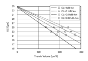
- Figure 9 is a diagram showing the relationship between the trench volume TV and the cladding thickness OCT when light with a wavelength of 1.31 ⁇ m is propagated through the core element 10 of the multicore fiber 1.
- Figure 9 was obtained by simulating a multicore fiber having a cladding 20 diameter of 100 ⁇ m, an outer diameter of the coating layer 30 of 160 ⁇ m, a bending radius of 76 mm, and a profile shown in Table 2 below.
- the cladding thickness OCT was set to 21.7 ⁇ m, 23.1 ⁇ m, 23.5 ⁇ m, 24.5 ⁇ m, and 25.3 ⁇ m, and the relationship between the confinement loss CL and the trench volume TV for each cladding thickness OCT was obtained.
- Figure 9 shows the relationship between the trench volume TV and the cladding thickness OCT when the confinement loss CL is constant.
- the confinement loss CL when light with a wavelength of 1.31 ⁇ m is propagated, if the trench volume TV is 105 ⁇ m 2 % or more, the confinement loss CL can be 0.01 dB/km or less even if the cladding thickness OCT is approximately 25.3 ⁇ m. In this case, if the trench volume TV is 190 ⁇ m 2 % or more, the confinement loss CL can be 0.01 dB/km or less even if the cladding thickness OCT is approximately 21.7 ⁇ m. In this case, if the trench volume TV is 135 ⁇ m 2 % or more, the confinement loss CL can be 0.001 dB/km or less even if the cladding thickness OCT is approximately 25.3 ⁇ m. In this case, if the trench volume TV is 215 ⁇ m 2 % or more, the confinement loss CL can be 0.001 dB/km or less even if the cladding thickness OCT is approximately 21.7 ⁇ m or less.
- Figure 10 shows the relationship between trench volume TV and cladding thickness OCT when light with a wavelength of 1.625 ⁇ m is propagated through core element 10 of multicore fiber 1 under the same conditions as in Figure 9.
- the confinement loss CL when light with a wavelength of 1.625 ⁇ m is propagated, if the trench volume TV is 196 ⁇ m 2 % or more, the confinement loss CL can be made 0.01 dB/km or less by setting the cladding thickness OCT to approximately 25.3 ⁇ m. In this case, if the trench volume TV is 269 ⁇ m 2 % or more, the confinement loss CL can be made 0.01 dB/km or less even if the cladding thickness OCT is approximately 21.7 ⁇ m. In this case, if the trench volume TV is 223 ⁇ m 2 % or more, the confinement loss CL can be made 0.001 dB/km or less by setting the cladding thickness OCT to approximately 25.3 ⁇ m. In this case, if the trench volume TV is 306 ⁇ m 2 % or more, the confinement loss CL can be made 0.001 dB/km or less even if the cladding thickness OCT is approximately 21.7 ⁇ m.
- the trench volume TV is 105 ⁇ m 2 % or more
- the core-to-core distance ⁇ is set to 35 ⁇ m or more
- the cladding thickness OCT is set to approximately 25.3 ⁇ m, so that the crosstalk XT from one adjacent core can be set to ⁇ 35 dB/km or less, and the confinement loss CL can be set to 0.01 dB/km or less. Therefore, if the trench volume TV is 105 ⁇ m 2 % or more, the diameter of the cladding 20 can be set to 104 ⁇ m or less while maintaining sufficient optical communication quality.
- the diameter of the cladding 20 can be reduced while maintaining sufficient optical communication quality. Also, if the trench volume TV is 135 ⁇ m 2 % or more, the confinement loss CL can be set to 0.001 dB/km or less under this condition.
- the core-to-core distance ⁇ can be set to approximately 40 ⁇ m and the cladding thickness OCT can be set to approximately 21.7 ⁇ m or less, so that the crosstalk XT from one adjacent core can be set to -35 dB/km or less and the confinement loss CL can be set to 0.01 dB/km or less. Therefore, if the trench volume TV is 190 ⁇ m 2 % or more, the diameter of the cladding 20 can be set to 104 ⁇ m or less while maintaining sufficient optical communication quality. In other words, the diameter of the cladding 20 can be reduced while maintaining sufficient optical communication quality.
- the crosstalk XT from one adjacent core can be set to -35 dB/km or less, so that the core-to-core distance ⁇ can be set to approximately 35 ⁇ m and the cladding thickness OCT can be set to approximately 21.7 ⁇ m, so that the diameter of the cladding 20 can be set to 93 ⁇ m or less.
- the confinement loss CL can be made 0.001 dB/km or less even if the cladding thickness OCT is approximately 21.7 ⁇ m.
- the trench volume TV is 234 ⁇ m 2 % or more
- the crosstalk XT from one adjacent core can be reduced to ⁇ 30 dB/km or less by setting the inter-core distance ⁇ to approximately 35 ⁇ m, and even if the cladding thickness OCT is approximately 25.3 ⁇ m, the confinement loss CL can be reduced to 0.01 dB/km or less. Therefore, if the trench volume TV is 234 ⁇ m 2 % or more, the diameter of the cladding 20 can be reduced to 100 ⁇ m or less while maintaining sufficient optical communication quality. Note that if the trench volume TV is 234 ⁇ m 2 % or more, the confinement loss CL can be reduced to 0.001 dB/km or less even if the cladding thickness OCT is approximately 25.3 ⁇ m.
- the core-to-core distance ⁇ can be set to 40 ⁇ m to reduce the crosstalk XT from one adjacent core to ⁇ 30 dB/km or less, and the cladding thickness OCT can be set to approximately 21.7 ⁇ m to reduce the confinement loss CL to 0.01 dB/km or less. Therefore, if the trench volume TV is 269 ⁇ m 2 % or more, the diameter of the cladding 20 can be set to 104 ⁇ m or less while maintaining sufficient optical communication quality. In other words, the diameter of the cladding 20 can be reduced while maintaining sufficient optical communication quality.
- the crosstalk XT from one adjacent core can be set to ⁇ 30 dB/km or less, so the core-to-core distance ⁇ can be set to approximately 35 ⁇ m and the cladding thickness OCT can be set to approximately 21.7 ⁇ m to reduce the diameter of the cladding 20 to 93 ⁇ m or less.
- the confinement loss CL can be made 0.001 dB/km or less.
- the cable cutoff wavelength ⁇ cc is set to 1.26 ⁇ m or less when light with a wavelength of 1.31 ⁇ m is propagated.
- the upper limit of the trench volume TV is 263 ⁇ m 2 % according to formula (3).
- the cable cutoff wavelength ⁇ cc is reduced by about 30 nm due to residual stress in the glass of the optical fiber in the drawing process. Therefore, the cable cutoff wavelength ⁇ cc can be reduced to 1.29 ⁇ m or less. Therefore, in this case, the upper limit of the trench volume TV is 290 ⁇ m 2 %.
- the upper limit of the trench volume TV is 350 ⁇ m 2 %.
- the outer diameter Dtrench of the trench layer 13 is in the range of 25 ⁇ m to 35.04 ⁇ m and the mode field diameter is in the range of 8.4 ⁇ m to 8.6 ⁇ m based on r3 in Table 2.
- the outer diameter Dtrench of the trench layer is 40 ⁇ m or less and the mode field diameter is 8.8 ⁇ m or less, as long as the trench volume TV satisfies 106 ⁇ m2 % or more and 350 ⁇ m2 % or less, there is almost no difference from the crosstalk described above and almost no difference from the confinement loss CL described above.
- the trench volume TV is 105 ⁇ m 2 % or more, by setting the inter-core distance ⁇ to 35 ⁇ m, the crosstalk XT from one adjacent core can be reduced to -35 dB/km or less, and by setting the cladding thickness OCT to approximately 25.3 ⁇ m, the confinement loss CL can be reduced to 0.01 dB/km or less while the diameter of the cladding 20 can be reduced to 85.6 ⁇ m. If the trench volume TV is 135 ⁇ m 2 % or more, the confinement loss CL can be further reduced to 0.001 dB/km or less.
- the confinement loss CL can be 0.01 dB/km or less, and the diameter of the cladding 20 can be reduced to 78.4 ⁇ m. If the trench volume TV is 215 ⁇ m 2 % or more, the confinement loss CL can be further reduced to 0.001 dB/km or less.
- the diameter of the cladding 20 can be reduced to 90 ⁇ m or less while maintaining sufficient optical communication quality. In other words, the diameter of the cladding 20 can be reduced while maintaining sufficient optical communication quality.
- the diameter of the cladding 20 can be reduced to 78.4 ⁇ m while the confinement loss CL is 0.01 dB/km or less, and if the trench volume TV is 306 ⁇ m 2 % or more, the confinement loss CL can be further reduced to 0.001 dB/km or less.
- the diameter of the cladding 20 can be reduced to 90 ⁇ m or less while maintaining sufficient optical communication quality. In other words, the diameter of the cladding 20 can be reduced while maintaining sufficient optical communication quality.
- the core elements 10 are arranged on a circumference CR centered on the center of the clad, so that the diameter of the clad 20 can be made to be a size between the diameter of the clad 20 when there are two core elements and the diameter of the clad 20 when there are four core elements.
- the core element 10 is described as including an outer core 12, but the outer core 12 is not a required component, and the core element 10 does not have to include the outer core 12.
- the present invention provides a multicore fiber that can reduce the cladding diameter while suppressing crosstalk and confinement loss, and can be used in the field of optical communications and other devices that use multicore fibers.
Landscapes
- Physics & Mathematics (AREA)
- General Physics & Mathematics (AREA)
- Optics & Photonics (AREA)
- Optical Fibers, Optical Fiber Cores, And Optical Fiber Bundles (AREA)
Abstract
Description
Dclad=21/2Λ+2OCT (1)
TV=(r32-r22)×π×|Δ3| (2)

隣接する1コアからのクロストークXTが-35dB/kmである場合:
Λ=-0.0415TV+34.9
隣接する1コアからのクロストークXTが-40dB/kmである場合:
Λ=-0.0413TV+36.3
隣接する1コアからのクロストークXTが-50dB/kmである場合:
Λ=-0.0407TV+39.1
隣接する1コアからのクロストークXTが-60dB/kmである場合:
Λ=-0.0402TV+41.9
隣接する1コアからのクロストークXTが-20dB/kmである場合:
Λ=-0.0524TV+43.2
隣接する1コアからのクロストークXTが-25dB/kmである場合:
Λ=-0.0522TV+45.3
隣接する1コアからのクロストークXTが-30dB/kmである場合:
Λ=-0.0521TV+47.2
隣接する1コアからのクロストークXTが-35dB/kmである場合:
Λ=-0.0519TV+49.2
隣接する1コアからのクロストークXTが-40dB/kmである場合:
Λ=-0.0518TV+51.2
閉じ込め損失CLが1dB/kmである場合:
OCT=-0.0343TV+26.3
閉じ込め損失CLが0.1dB/kmである場合:
OCT=-0.0380TV+27.9
閉じ込め損失CLが0.01dB/kmである場合:
OCT=-0.0420TV+29.7
閉じ込め損失CLが0.001dB/kmである場合:
OCT=-0.0452TV+31.4
閉じ込め損失CLが1dB/kmである場合:
OCT=-0.0707TV+34.7
閉じ込め損失CLが0.1dB/kmである場合:
OCT=-0.0589TV+35.1
閉じ込め損失CLが0.01dB/kmである場合:
OCT=-0.0494TV+35.0
閉じ込め損失CLが0.001dB/kmである場合:
OCT=-0.0431TV+34.9
λcc=0.0011TV+0.9707 (3)
Dclad=Λ+2OCT (4)
Claims (7)
- コア及び前記コアの外周面を囲うトレンチ層を含む2つから4つのコア要素と、
それぞれのコア要素の外周面を隙間なく囲うクラッドと、
を備え、
それぞれの前記コア要素は、前記クラッドの中心を中心とする円周上に配置され、
前記コア要素の直径は、当該コア要素と最短で隣り合う他の前記コア要素とのコア間距離から1μm小さい大きさ以下であり、
前記コアを波長1.31μmの光が伝搬する場合における当該光のモードフィールド径は、8.8μm以下であり、
前記クラッドの長手方向に垂直な断面における前記トレンチ層の断面積と、前記トレンチ層の前記クラッドに対する比屈折率差の絶対値との積であるトレンチボリュームが105μm2%以上350μm2%以下である
ことを特徴とするマルチコアファイバ。 - 前記トレンチボリュームが136μm2%以上である
ことを特徴とする請求項1に記載のマルチコアファイバ。 - 前記トレンチボリュームが190μm2%以上である
ことを特徴とする請求項1に記載のマルチコアファイバ。 - 前記トレンチボリュームが214μm2%以上である
ことを特徴とする請求項1に記載のマルチコアファイバ。 - 前記トレンチボリュームが234μm2%以上である
ことを特徴とする請求項1に記載のマルチコアファイバ。 - 前記トレンチボリュームが269.7μm2%以上である
ことを特徴とする請求項1に記載のマルチコアファイバ。 - 前記トレンチボリュームが306μm2%以上である
ことを特徴とする請求項1に記載のマルチコアファイバ。
Priority Applications (3)
| Application Number | Priority Date | Filing Date | Title |
|---|---|---|---|
| JP2025527885A JPWO2024257700A1 (ja) | 2023-06-16 | 2024-06-07 | |
| EP24823316.5A EP4729997A1 (en) | 2023-06-16 | 2024-06-07 | Multicore fiber |
| CN202480027788.7A CN121002414A (zh) | 2023-06-16 | 2024-06-07 | 多芯光纤 |
Applications Claiming Priority (2)
| Application Number | Priority Date | Filing Date | Title |
|---|---|---|---|
| JP2023099446 | 2023-06-16 | ||
| JP2023-099446 | 2023-06-16 |
Publications (1)
| Publication Number | Publication Date |
|---|---|
| WO2024257700A1 true WO2024257700A1 (ja) | 2024-12-19 |
Family
ID=93852117
Family Applications (1)
| Application Number | Title | Priority Date | Filing Date |
|---|---|---|---|
| PCT/JP2024/020843 Ceased WO2024257700A1 (ja) | 2023-06-16 | 2024-06-07 | マルチコアファイバ |
Country Status (4)
| Country | Link |
|---|---|
| EP (1) | EP4729997A1 (ja) |
| JP (1) | JPWO2024257700A1 (ja) |
| CN (1) | CN121002414A (ja) |
| WO (1) | WO2024257700A1 (ja) |
Citations (4)
| Publication number | Priority date | Publication date | Assignee | Title |
|---|---|---|---|---|
| WO2014087974A1 (ja) * | 2012-12-05 | 2014-06-12 | 住友電気工業株式会社 | 光導波路および光ファイバ伝送系 |
| US20170336559A1 (en) * | 2016-05-17 | 2017-11-23 | Corning Incorporated | Optical fiber for both multimode and single-mode operation and transmission system therefor |
| JP2018021999A (ja) * | 2016-08-02 | 2018-02-08 | 日本電信電話株式会社 | 光ファイバ及び光伝送システム |
| JP2020086054A (ja) | 2018-11-21 | 2020-06-04 | 日本電信電話株式会社 | マルチコア光ファイバ、マルチコア光ファイバ設計方法、および光伝送方法 |
-
2024
- 2024-06-07 WO PCT/JP2024/020843 patent/WO2024257700A1/ja not_active Ceased
- 2024-06-07 CN CN202480027788.7A patent/CN121002414A/zh active Pending
- 2024-06-07 EP EP24823316.5A patent/EP4729997A1/en active Pending
- 2024-06-07 JP JP2025527885A patent/JPWO2024257700A1/ja active Pending
Patent Citations (4)
| Publication number | Priority date | Publication date | Assignee | Title |
|---|---|---|---|---|
| WO2014087974A1 (ja) * | 2012-12-05 | 2014-06-12 | 住友電気工業株式会社 | 光導波路および光ファイバ伝送系 |
| US20170336559A1 (en) * | 2016-05-17 | 2017-11-23 | Corning Incorporated | Optical fiber for both multimode and single-mode operation and transmission system therefor |
| JP2018021999A (ja) * | 2016-08-02 | 2018-02-08 | 日本電信電話株式会社 | 光ファイバ及び光伝送システム |
| JP2020086054A (ja) | 2018-11-21 | 2020-06-04 | 日本電信電話株式会社 | マルチコア光ファイバ、マルチコア光ファイバ設計方法、および光伝送方法 |
Also Published As
| Publication number | Publication date |
|---|---|
| CN121002414A (zh) | 2025-11-21 |
| EP4729997A1 (en) | 2026-04-22 |
| JPWO2024257700A1 (ja) | 2024-12-19 |
Similar Documents
| Publication | Publication Date | Title |
|---|---|---|
| EP3532880B1 (en) | Low bend loss single mode optical fiber | |
| JP5916525B2 (ja) | マルチコアファイバ | |
| CN1133884C (zh) | 在铒放大器领域的具有低色散斜率的光纤 | |
| JP5855351B2 (ja) | マルチコアファイバ | |
| CN106575013A (zh) | 多芯光纤、光缆及光连接器 | |
| JP5222752B2 (ja) | 光ファイバ | |
| CN114384626B (zh) | 多芯光纤及多芯光缆 | |
| US9835812B2 (en) | Multi-optical fiber aggregate | |
| CN108474903A (zh) | 多芯光纤 | |
| WO2020162406A1 (ja) | 光ファイバ | |
| CN116194811A (zh) | 多纤芯光纤 | |
| CN117136321A (zh) | 光纤 | |
| JPWO2013108524A1 (ja) | マルチコアファイバ | |
| CN106662705B (zh) | 光纤 | |
| JP7508294B2 (ja) | マルチコアファイバおよびその製造方法 | |
| CN102959439A (zh) | 光纤、光纤软线及光缆 | |
| WO2020241531A1 (ja) | 光ファイバ | |
| JP4533388B2 (ja) | 中程度の分散を有するnzdsfに対する分散補償ファイバおよびこれを使用する伝送システム | |
| WO2023086219A1 (en) | Reduced clad dual-core optical fibers for optical fiber cables and optical fiber interconnects | |
| CN110824610B (zh) | 一种弯曲不敏感单模光纤 | |
| JP6096268B2 (ja) | マルチコアファイバ | |
| JP4861181B2 (ja) | 標準的なシングルモードファイバに対する、高性能指数の分散補償ファイバおよび当該分散補償ファイバを使用する伝送システム | |
| WO2024257700A1 (ja) | マルチコアファイバ | |
| CN120457369A (zh) | 多芯光纤 | |
| WO2024116792A1 (ja) | マルチコア光ファイバ |
Legal Events
| Date | Code | Title | Description |
|---|---|---|---|
| 121 | Ep: the epo has been informed by wipo that ep was designated in this application |
Ref document number: 24823316 Country of ref document: EP Kind code of ref document: A1 |
|
| ENP | Entry into the national phase |
Ref document number: 2025527885 Country of ref document: JP Kind code of ref document: A |
|
| WWE | Wipo information: entry into national phase |
Ref document number: 2025527885 Country of ref document: JP |
|
| WWE | Wipo information: entry into national phase |
Ref document number: 2024823316 Country of ref document: EP |
|
| NENP | Non-entry into the national phase |
Ref country code: DE |
|
| ENP | Entry into the national phase |
Ref document number: 2024823316 Country of ref document: EP Effective date: 20260116 |
|
| ENP | Entry into the national phase |
Ref document number: 2024823316 Country of ref document: EP Effective date: 20260116 |
|
| ENP | Entry into the national phase |
Ref document number: 2024823316 Country of ref document: EP Effective date: 20260116 |