WO2020241604A1 - Système de moteur - Google Patents
Système de moteur Download PDFInfo
- Publication number
- WO2020241604A1 WO2020241604A1 PCT/JP2020/020640 JP2020020640W WO2020241604A1 WO 2020241604 A1 WO2020241604 A1 WO 2020241604A1 JP 2020020640 W JP2020020640 W JP 2020020640W WO 2020241604 A1 WO2020241604 A1 WO 2020241604A1
- Authority
- WO
- WIPO (PCT)
- Prior art keywords
- engine
- reforming
- control unit
- throttle valve
- valve
- Prior art date
- Legal status (The legal status is an assumption and is not a legal conclusion. Google has not performed a legal analysis and makes no representation as to the accuracy of the status listed.)
- Ceased
Links
Images






Classifications
-
- F—MECHANICAL ENGINEERING; LIGHTING; HEATING; WEAPONS; BLASTING
- F02—COMBUSTION ENGINES; HOT-GAS OR COMBUSTION-PRODUCT ENGINE PLANTS
- F02M—SUPPLYING COMBUSTION ENGINES IN GENERAL WITH COMBUSTIBLE MIXTURES OR CONSTITUENTS THEREOF
- F02M21/00—Apparatus for supplying engines with non-liquid fuels, e.g. gaseous fuels stored in liquid form
- F02M21/02—Apparatus for supplying engines with non-liquid fuels, e.g. gaseous fuels stored in liquid form for gaseous fuels
- F02M21/0203—Apparatus for supplying engines with non-liquid fuels, e.g. gaseous fuels stored in liquid form for gaseous fuels characterised by the type of gaseous fuel
- F02M21/0206—Non-hydrocarbon fuels, e.g. hydrogen, ammonia or carbon monoxide
-
- C—CHEMISTRY; METALLURGY
- C01—INORGANIC CHEMISTRY
- C01B—NON-METALLIC ELEMENTS; COMPOUNDS THEREOF; METALLOIDS OR COMPOUNDS THEREOF NOT COVERED BY SUBCLASS C01C
- C01B3/00—Hydrogen; Gaseous mixtures containing hydrogen; Separation of hydrogen from mixtures containing it; Purification of hydrogen; Reversible storage of hydrogen
- C01B3/02—Production of hydrogen; Production of gaseous mixtures containing hydrogen
- C01B3/04—Production of hydrogen; Production of gaseous mixtures containing hydrogen by decomposition of inorganic compounds
-
- F—MECHANICAL ENGINEERING; LIGHTING; HEATING; WEAPONS; BLASTING
- F01—MACHINES OR ENGINES IN GENERAL; ENGINE PLANTS IN GENERAL; STEAM ENGINES
- F01N—GAS-FLOW SILENCERS OR EXHAUST APPARATUS FOR MACHINES OR ENGINES IN GENERAL; GAS-FLOW SILENCERS OR EXHAUST APPARATUS FOR INTERNAL-COMBUSTION ENGINES
- F01N3/00—Exhaust or silencing apparatus having means for purifying, rendering innocuous, or otherwise treating exhaust
- F01N3/08—Exhaust or silencing apparatus having means for purifying, rendering innocuous, or otherwise treating exhaust for rendering innocuous
- F01N3/10—Exhaust or silencing apparatus having means for purifying, rendering innocuous, or otherwise treating exhaust for rendering innocuous by thermal or catalytic conversion of noxious components of exhaust
- F01N3/101—Three-way catalysts
-
- F—MECHANICAL ENGINEERING; LIGHTING; HEATING; WEAPONS; BLASTING
- F01—MACHINES OR ENGINES IN GENERAL; ENGINE PLANTS IN GENERAL; STEAM ENGINES
- F01N—GAS-FLOW SILENCERS OR EXHAUST APPARATUS FOR MACHINES OR ENGINES IN GENERAL; GAS-FLOW SILENCERS OR EXHAUST APPARATUS FOR INTERNAL-COMBUSTION ENGINES
- F01N3/00—Exhaust or silencing apparatus having means for purifying, rendering innocuous, or otherwise treating exhaust
- F01N3/08—Exhaust or silencing apparatus having means for purifying, rendering innocuous, or otherwise treating exhaust for rendering innocuous
- F01N3/10—Exhaust or silencing apparatus having means for purifying, rendering innocuous, or otherwise treating exhaust for rendering innocuous by thermal or catalytic conversion of noxious components of exhaust
- F01N3/18—Exhaust or silencing apparatus having means for purifying, rendering innocuous, or otherwise treating exhaust for rendering innocuous by thermal or catalytic conversion of noxious components of exhaust characterised by methods of operation; Control
- F01N3/20—Exhaust or silencing apparatus having means for purifying, rendering innocuous, or otherwise treating exhaust for rendering innocuous by thermal or catalytic conversion of noxious components of exhaust characterised by methods of operation; Control specially adapted for catalytic conversion
- F01N3/206—Adding periodically or continuously substances to exhaust gases for promoting purification, e.g. catalytic material in liquid form, NOx reducing agents
- F01N3/2066—Selective catalytic reduction [SCR]
-
- F—MECHANICAL ENGINEERING; LIGHTING; HEATING; WEAPONS; BLASTING
- F02—COMBUSTION ENGINES; HOT-GAS OR COMBUSTION-PRODUCT ENGINE PLANTS
- F02B—INTERNAL-COMBUSTION PISTON ENGINES; COMBUSTION ENGINES IN GENERAL
- F02B43/00—Engines characterised by operating on gaseous fuels; Plants including such engines
- F02B43/10—Engines or plants characterised by use of other specific gases, e.g. acetylene, oxyhydrogen
-
- F—MECHANICAL ENGINEERING; LIGHTING; HEATING; WEAPONS; BLASTING
- F02—COMBUSTION ENGINES; HOT-GAS OR COMBUSTION-PRODUCT ENGINE PLANTS
- F02B—INTERNAL-COMBUSTION PISTON ENGINES; COMBUSTION ENGINES IN GENERAL
- F02B51/00—Other methods of operating engines involving pretreating of, or adding substances to, combustion air, fuel, or fuel-air mixture of the engines
- F02B51/02—Other methods of operating engines involving pretreating of, or adding substances to, combustion air, fuel, or fuel-air mixture of the engines involving catalysts
-
- F—MECHANICAL ENGINEERING; LIGHTING; HEATING; WEAPONS; BLASTING
- F02—COMBUSTION ENGINES; HOT-GAS OR COMBUSTION-PRODUCT ENGINE PLANTS
- F02D—CONTROLLING COMBUSTION ENGINES
- F02D19/00—Controlling engines characterised by their use of non-liquid fuels, pluralities of fuels, or non-fuel substances added to the combustible mixtures
- F02D19/02—Controlling engines characterised by their use of non-liquid fuels, pluralities of fuels, or non-fuel substances added to the combustible mixtures peculiar to engines working with gaseous fuels
- F02D19/021—Control of components of the fuel supply system
- F02D19/023—Control of components of the fuel supply system to adjust the fuel mass or volume flow
- F02D19/024—Control of components of the fuel supply system to adjust the fuel mass or volume flow by controlling fuel injectors
-
- F—MECHANICAL ENGINEERING; LIGHTING; HEATING; WEAPONS; BLASTING
- F02—COMBUSTION ENGINES; HOT-GAS OR COMBUSTION-PRODUCT ENGINE PLANTS
- F02D—CONTROLLING COMBUSTION ENGINES
- F02D19/00—Controlling engines characterised by their use of non-liquid fuels, pluralities of fuels, or non-fuel substances added to the combustible mixtures
- F02D19/06—Controlling engines characterised by their use of non-liquid fuels, pluralities of fuels, or non-fuel substances added to the combustible mixtures peculiar to engines working with pluralities of fuels, e.g. alternatively with light and heavy fuel oil, other than engines indifferent to the fuel consumed
- F02D19/0626—Measuring or estimating parameters related to the fuel supply system
- F02D19/0628—Determining the fuel pressure, temperature or flow, the fuel tank fill level or a valve position
-
- F—MECHANICAL ENGINEERING; LIGHTING; HEATING; WEAPONS; BLASTING
- F02—COMBUSTION ENGINES; HOT-GAS OR COMBUSTION-PRODUCT ENGINE PLANTS
- F02D—CONTROLLING COMBUSTION ENGINES
- F02D19/00—Controlling engines characterised by their use of non-liquid fuels, pluralities of fuels, or non-fuel substances added to the combustible mixtures
- F02D19/06—Controlling engines characterised by their use of non-liquid fuels, pluralities of fuels, or non-fuel substances added to the combustible mixtures peculiar to engines working with pluralities of fuels, e.g. alternatively with light and heavy fuel oil, other than engines indifferent to the fuel consumed
- F02D19/0639—Controlling engines characterised by their use of non-liquid fuels, pluralities of fuels, or non-fuel substances added to the combustible mixtures peculiar to engines working with pluralities of fuels, e.g. alternatively with light and heavy fuel oil, other than engines indifferent to the fuel consumed characterised by the type of fuels
- F02D19/0642—Controlling engines characterised by their use of non-liquid fuels, pluralities of fuels, or non-fuel substances added to the combustible mixtures peculiar to engines working with pluralities of fuels, e.g. alternatively with light and heavy fuel oil, other than engines indifferent to the fuel consumed characterised by the type of fuels at least one fuel being gaseous, the other fuels being gaseous or liquid at standard conditions
- F02D19/0644—Controlling engines characterised by their use of non-liquid fuels, pluralities of fuels, or non-fuel substances added to the combustible mixtures peculiar to engines working with pluralities of fuels, e.g. alternatively with light and heavy fuel oil, other than engines indifferent to the fuel consumed characterised by the type of fuels at least one fuel being gaseous, the other fuels being gaseous or liquid at standard conditions the gaseous fuel being hydrogen, ammonia or carbon monoxide
-
- F—MECHANICAL ENGINEERING; LIGHTING; HEATING; WEAPONS; BLASTING
- F02—COMBUSTION ENGINES; HOT-GAS OR COMBUSTION-PRODUCT ENGINE PLANTS
- F02D—CONTROLLING COMBUSTION ENGINES
- F02D19/00—Controlling engines characterised by their use of non-liquid fuels, pluralities of fuels, or non-fuel substances added to the combustible mixtures
- F02D19/06—Controlling engines characterised by their use of non-liquid fuels, pluralities of fuels, or non-fuel substances added to the combustible mixtures peculiar to engines working with pluralities of fuels, e.g. alternatively with light and heavy fuel oil, other than engines indifferent to the fuel consumed
- F02D19/0663—Details on the fuel supply system, e.g. tanks, valves, pipes, pumps, rails, injectors or mixers
- F02D19/0668—Treating or cleaning means; Fuel filters
- F02D19/0671—Means to generate or modify a fuel, e.g. reformers, electrolytic cells or membranes
-
- F—MECHANICAL ENGINEERING; LIGHTING; HEATING; WEAPONS; BLASTING
- F02—COMBUSTION ENGINES; HOT-GAS OR COMBUSTION-PRODUCT ENGINE PLANTS
- F02D—CONTROLLING COMBUSTION ENGINES
- F02D41/00—Electrical control of supply of combustible mixture or its constituents
- F02D41/0025—Controlling engines characterised by use of non-liquid fuels, pluralities of fuels, or non-fuel substances added to the combustible mixtures
- F02D41/0027—Controlling engines characterised by use of non-liquid fuels, pluralities of fuels, or non-fuel substances added to the combustible mixtures the fuel being gaseous
-
- F—MECHANICAL ENGINEERING; LIGHTING; HEATING; WEAPONS; BLASTING
- F02—COMBUSTION ENGINES; HOT-GAS OR COMBUSTION-PRODUCT ENGINE PLANTS
- F02D—CONTROLLING COMBUSTION ENGINES
- F02D41/00—Electrical control of supply of combustible mixture or its constituents
- F02D41/02—Circuit arrangements for generating control signals
- F02D41/04—Introducing corrections for particular operating conditions
- F02D41/042—Introducing corrections for particular operating conditions for stopping the engine
-
- F—MECHANICAL ENGINEERING; LIGHTING; HEATING; WEAPONS; BLASTING
- F02—COMBUSTION ENGINES; HOT-GAS OR COMBUSTION-PRODUCT ENGINE PLANTS
- F02D—CONTROLLING COMBUSTION ENGINES
- F02D9/00—Controlling engines by throttling air or fuel-and-air induction conduits or exhaust conduits
- F02D9/02—Controlling engines by throttling air or fuel-and-air induction conduits or exhaust conduits concerning induction conduits
-
- F—MECHANICAL ENGINEERING; LIGHTING; HEATING; WEAPONS; BLASTING
- F02—COMBUSTION ENGINES; HOT-GAS OR COMBUSTION-PRODUCT ENGINE PLANTS
- F02M—SUPPLYING COMBUSTION ENGINES IN GENERAL WITH COMBUSTIBLE MIXTURES OR CONSTITUENTS THEREOF
- F02M21/00—Apparatus for supplying engines with non-liquid fuels, e.g. gaseous fuels stored in liquid form
- F02M21/02—Apparatus for supplying engines with non-liquid fuels, e.g. gaseous fuels stored in liquid form for gaseous fuels
-
- F—MECHANICAL ENGINEERING; LIGHTING; HEATING; WEAPONS; BLASTING
- F02—COMBUSTION ENGINES; HOT-GAS OR COMBUSTION-PRODUCT ENGINE PLANTS
- F02M—SUPPLYING COMBUSTION ENGINES IN GENERAL WITH COMBUSTIBLE MIXTURES OR CONSTITUENTS THEREOF
- F02M27/00—Apparatus for treating combustion-air, fuel, or fuel-air mixture, by catalysts, electric means, magnetism, rays, sound waves, or the like
- F02M27/02—Apparatus for treating combustion-air, fuel, or fuel-air mixture, by catalysts, electric means, magnetism, rays, sound waves, or the like by catalysts
-
- F—MECHANICAL ENGINEERING; LIGHTING; HEATING; WEAPONS; BLASTING
- F01—MACHINES OR ENGINES IN GENERAL; ENGINE PLANTS IN GENERAL; STEAM ENGINES
- F01N—GAS-FLOW SILENCERS OR EXHAUST APPARATUS FOR MACHINES OR ENGINES IN GENERAL; GAS-FLOW SILENCERS OR EXHAUST APPARATUS FOR INTERNAL-COMBUSTION ENGINES
- F01N2240/00—Combination or association of two or more different exhaust treating devices, or of at least one such device with an auxiliary device, not covered by indexing codes F01N2230/00 or F01N2250/00, one of the devices being
- F01N2240/30—Combination or association of two or more different exhaust treating devices, or of at least one such device with an auxiliary device, not covered by indexing codes F01N2230/00 or F01N2250/00, one of the devices being a fuel reformer
-
- F—MECHANICAL ENGINEERING; LIGHTING; HEATING; WEAPONS; BLASTING
- F01—MACHINES OR ENGINES IN GENERAL; ENGINE PLANTS IN GENERAL; STEAM ENGINES
- F01N—GAS-FLOW SILENCERS OR EXHAUST APPARATUS FOR MACHINES OR ENGINES IN GENERAL; GAS-FLOW SILENCERS OR EXHAUST APPARATUS FOR INTERNAL-COMBUSTION ENGINES
- F01N2610/00—Adding substances to exhaust gases
- F01N2610/02—Adding substances to exhaust gases the substance being ammonia or urea
-
- F—MECHANICAL ENGINEERING; LIGHTING; HEATING; WEAPONS; BLASTING
- F01—MACHINES OR ENGINES IN GENERAL; ENGINE PLANTS IN GENERAL; STEAM ENGINES
- F01N—GAS-FLOW SILENCERS OR EXHAUST APPARATUS FOR MACHINES OR ENGINES IN GENERAL; GAS-FLOW SILENCERS OR EXHAUST APPARATUS FOR INTERNAL-COMBUSTION ENGINES
- F01N3/00—Exhaust or silencing apparatus having means for purifying, rendering innocuous, or otherwise treating exhaust
- F01N3/08—Exhaust or silencing apparatus having means for purifying, rendering innocuous, or otherwise treating exhaust for rendering innocuous
- F01N3/0807—Exhaust or silencing apparatus having means for purifying, rendering innocuous, or otherwise treating exhaust for rendering innocuous by using absorbents or adsorbents
- F01N3/0828—Exhaust or silencing apparatus having means for purifying, rendering innocuous, or otherwise treating exhaust for rendering innocuous by using absorbents or adsorbents characterised by the absorbed or adsorbed substances
- F01N3/0842—Nitrogen oxides
-
- F—MECHANICAL ENGINEERING; LIGHTING; HEATING; WEAPONS; BLASTING
- F02—COMBUSTION ENGINES; HOT-GAS OR COMBUSTION-PRODUCT ENGINE PLANTS
- F02D—CONTROLLING COMBUSTION ENGINES
- F02D19/00—Controlling engines characterised by their use of non-liquid fuels, pluralities of fuels, or non-fuel substances added to the combustible mixtures
- F02D19/06—Controlling engines characterised by their use of non-liquid fuels, pluralities of fuels, or non-fuel substances added to the combustible mixtures peculiar to engines working with pluralities of fuels, e.g. alternatively with light and heavy fuel oil, other than engines indifferent to the fuel consumed
- F02D19/0663—Details on the fuel supply system, e.g. tanks, valves, pipes, pumps, rails, injectors or mixers
- F02D19/0686—Injectors
- F02D19/0692—Arrangement of multiple injectors per combustion chamber
-
- F—MECHANICAL ENGINEERING; LIGHTING; HEATING; WEAPONS; BLASTING
- F02—COMBUSTION ENGINES; HOT-GAS OR COMBUSTION-PRODUCT ENGINE PLANTS
- F02D—CONTROLLING COMBUSTION ENGINES
- F02D9/00—Controlling engines by throttling air or fuel-and-air induction conduits or exhaust conduits
- F02D9/02—Controlling engines by throttling air or fuel-and-air induction conduits or exhaust conduits concerning induction conduits
- F02D2009/0201—Arrangements; Control features; Details thereof
- F02D2009/0279—Throttle valve control for intake system with two parallel air flow paths, each controlled by a throttle, e.g. a resilient flap disposed on a throttle
-
- F—MECHANICAL ENGINEERING; LIGHTING; HEATING; WEAPONS; BLASTING
- F02—COMBUSTION ENGINES; HOT-GAS OR COMBUSTION-PRODUCT ENGINE PLANTS
- F02D—CONTROLLING COMBUSTION ENGINES
- F02D2200/00—Input parameters for engine control
- F02D2200/02—Input parameters for engine control the parameters being related to the engine
- F02D2200/06—Fuel or fuel supply system parameters
- F02D2200/0606—Fuel temperature
-
- Y—GENERAL TAGGING OF NEW TECHNOLOGICAL DEVELOPMENTS; GENERAL TAGGING OF CROSS-SECTIONAL TECHNOLOGIES SPANNING OVER SEVERAL SECTIONS OF THE IPC; TECHNICAL SUBJECTS COVERED BY FORMER USPC CROSS-REFERENCE ART COLLECTIONS [XRACs] AND DIGESTS
- Y02—TECHNOLOGIES OR APPLICATIONS FOR MITIGATION OR ADAPTATION AGAINST CLIMATE CHANGE
- Y02E—REDUCTION OF GREENHOUSE GAS [GHG] EMISSIONS, RELATED TO ENERGY GENERATION, TRANSMISSION OR DISTRIBUTION
- Y02E60/00—Enabling technologies; Technologies with a potential or indirect contribution to GHG emissions mitigation
- Y02E60/30—Hydrogen technology
- Y02E60/36—Hydrogen production from non-carbon containing sources, e.g. by water electrolysis
Definitions
- the present invention relates to an engine system.
- the engine system described in Patent Document 1 includes an engine main body, an engine intake passage and an engine exhaust passage connected to the combustion chamber of the engine main body, a throttle valve arranged inside the engine intake passage, and an engine intake passage.
- an ammonia injection valve that injects gaseous ammonia toward it
- a decomposer that decomposes gaseous ammonia with a catalyst to generate hydrogen
- an ammonia supply pipe that supplies gaseous ammonia to this decomposer
- an engine intake passage It is provided with an air supply pipe that supplies air to the decomposer and an outflow pipe that is connected to the engine intake passage and outflows a gas containing hydrogen generated by the decomposer.
- the above-mentioned conventional technology has the following problems. That is, when reforming gaseous ammonia in the decomposer (reform part), a part of the ammonia is burned and the remaining ammonia is separated by using the combustion heat to reform the gas containing hydrogen. Is being taken out. At this time, the reforming gas may contain water vapor. If steam remains in the reforming path, the steam will be cooled and condensed when the engine is stopped. If the water vapor remaining in the reforming path is condensed, the catalyst in the reforming part may be submerged and the function of the catalyst may be deteriorated, or the path of the reforming gas may be blocked by freezing of water under the freezing point condition.
- An object of the present invention is to provide an engine system capable of preventing the condensation of water vapor remaining in the reforming path when the engine is stopped.
- the engine system is arranged in an engine, an intake passage through which air supplied to the engine flows, a fuel injection valve for injecting fuel toward the engine, and an intake passage, and is supplied to the engine. It has a first throttle valve that controls the flow rate of the air, a catalyst that decomposes the fuel into hydrogen, and supplies it to the reforming section and the reforming section that reforms the fuel to generate reformed gas containing hydrogen.
- the reforming gas flow path through which the reforming gas generated by the reforming section flows toward the engine, the stop instruction section that instructs the engine to stop, the fuel injection valve, the first throttle valve, the fuel supply valve, and the first It is equipped with a control unit that controls two throttle valves, and the control unit controls to close one of the fuel supply valve and the second throttle valve after the stop instruction unit instructs to stop the engine, and also supplies fuel. It has a first control unit that controls to open the other of the fuel valve and the second throttle valve, and a second control unit that controls to close the fuel injection valve after the stop instruction unit instructs the engine to stop. ..
- one of the fuel supply valve and the second throttle valve is controlled to be closed, and the other of the fuel supply valve and the second throttle valve is opened.
- the fuel injection valve controls the fuel injection valve to be closed after the instruction to stop the engine is instructed, the supply of fuel to the engine is stopped and the engine is stopped. In this way, when the engine is stopped, the inside of the reforming path is purged, so that there is no water vapor in the reforming path. This prevents the condensation of water vapor remaining in the reforming path.
- the second control unit controls to close the fuel injection valve and the first throttle valve after the control process by the first control unit is executed, and closes one of the fuel supply valve and the second throttle valve. You may control it.
- the engine system further includes a temperature detection unit that detects the temperature of the reforming unit, and the control unit executes control processing by the first control unit and the second control unit when the stop instruction unit instructs the engine to stop.
- the first control unit has a third control unit that controls the fuel supply valve and the second throttle valve so as to reduce the supply amount of fuel and air to the reforming unit. After the control process by the unit is executed, when the temperature of the reforming unit detected by the temperature detection unit falls below the specified temperature, the fuel supply valve is controlled to close and the second throttle valve is controlled to open. Then, the second control unit may control to close the fuel injection valve and the first throttle valve after the control process by the first control unit is executed, and may also control to close the second throttle valve. ..
- the second control unit controls to close the fuel injection valve and the first throttle valve after a lapse of a specified time from the execution of the control process by the first control unit, and also controls to close the second throttle valve. You may.
- the engine can be stopped in a state where the gas in the reforming path is replaced with air (fresh air).
- the second control unit controls to close the fuel injection valve and the fuel supply valve after the stop instruction unit instructs to stop the engine, and the first control unit executes the control process by the second control unit. After that, the fuel supply valve may be controlled to be closed, and the first throttle valve and the second throttle valve may be controlled to be opened.
- the engine system further includes a motor for starting the engine, and the first control unit controls to open the first throttle valve and the second throttle valve after the control process by the second control unit is executed, and also controls the engine.
- the motor may be controlled so as to crank the engine by a specified number of revolutions.
- the engine system further includes a temperature detection unit that detects the temperature of the reforming unit, and the control unit executes control processing by the second control unit and the first control unit when the stop instruction unit instructs the engine to stop. It has a third control unit that controls a fuel supply valve and a second throttle valve so as to reduce the amount of fuel and air supplied to the reforming unit, and the second control unit has a third control. After the control process by the unit is executed, when the temperature of the reforming unit detected by the temperature detection unit becomes equal to or lower than the specified temperature, the fuel injection valve and the fuel supply valve may be controlled to be closed.
- the temperature of the catalyst in the reforming section is lowered by reducing the supply amount of fuel and air to the reforming section before purging in the reforming path, so that the catalyst is oxidatively deteriorated. Can be prevented.
- the first control unit controls to close the first throttle valve and the second throttle valve after the stop instruction unit instructs to stop the engine, and also controls to open the fuel supply valve, and the second control The unit may be controlled to close the fuel injection valve and the fuel supply valve after the control process by the first control unit is executed.
- the engine system further includes a stop valve that opens and closes the reforming gas flow path, and the second control unit controls to close the fuel injection valve and the fuel supply valve, and then controls to close the stop valve. It may be controlled to open the first throttle valve.
- the engine system further includes a temperature detection unit that detects the temperature of the reforming unit, and the control unit executes control processing by the first control unit and the second control unit when the stop instruction unit instructs the engine to stop. It has a third control unit that controls a fuel supply valve and a second throttle valve so as to reduce the amount of fuel and air supplied to the reforming unit, and the first control unit has a third control. After the control process by the unit is executed, when the temperature of the reforming unit detected by the temperature detection unit falls below the specified temperature, the first throttle valve and the second throttle valve are controlled to be closed and the fuel supply valve is controlled. May be controlled to open.
- the temperature of the catalyst in the reforming section is lowered by reducing the supply amount of fuel and air to the reforming section before purging in the reforming path, so that the catalyst is oxidatively deteriorated. Can be prevented.
- the engine may be an ammonia engine that uses ammonia as fuel. When hydrogen is mixed with ammonia in an engine, ammonia is easily burned. Therefore, it is effective to apply the engine system of the present invention to an ammonia engine.
- FIG. 5 is a flowchart showing details of a stop control processing procedure executed by the stop control processing unit shown in FIG.
- FIG. 7 shows the structure of the control system of the engine system shown in FIG. 7.
- FIG. 5 is a flowchart showing details of a stop control processing procedure executed by the stop control processing unit shown in FIG.
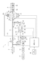
- FIG. 1 is a schematic configuration diagram showing an engine system according to the first embodiment of the present invention.
- the engine system 1 of the present embodiment is mounted on a vehicle.
- the engine system 1 includes an ammonia engine 2, an intake passage 3, an exhaust passage 4, a plurality of (four in this case) main injectors 5, and a main throttle valve 6.
- the ammonia engine 2 is an engine that uses ammonia (NH 3 ) as fuel.
- the ammonia engine 2 is, for example, a 4-cylinder engine and has four combustion chambers 2a.
- Hydrogen (H 2 ) is supplied to the combustion chamber 2a together with ammonia. As a result, hydrogen is mixed with ammonia in the combustion chamber 2a, so that ammonia is easily burned.
- the intake passage 3 is connected to the combustion chamber 2a.
- the intake passage 3 is a passage through which air supplied to the combustion chamber 2a of the ammonia engine 2 flows.
- An air cleaner 7 for removing dust and foreign matter such as dust contained in the air is provided in the intake passage 3.
- the exhaust passage 4 is connected to the combustion chamber 2a.
- the exhaust passage 4 is a passage through which the exhaust gas generated from the combustion chamber 2a flows.
- An exhaust purification catalyst 8 for removing harmful substances such as nitrogen oxides (NOx) and ammonia contained in the exhaust gas is arranged in the exhaust passage 4.
- the exhaust gas purification catalyst 8 for example, a three-way catalyst, an SCR (Selective Catalytic Reduction) catalyst, or the like is used (described later).
- the main injector 5 is an electromagnetic type fuel injection valve toward the combustion chamber 2a of the ammonia engine 2 to inject ammonia gas (NH 3 gas).
- the main injector 5 is connected to a vaporizer 12 described later via an ammonia gas flow path 9.
- the ammonia gas flow path 9 is a flow path through which ammonia gas flows.
- the main injector 5 is attached to the ammonia engine 2.
- the main throttle valve 6 is arranged between the air cleaner 7 and the ammonia engine 2 in the intake passage 3.
- the main throttle valve 6 is a first throttle valve that controls the flow rate of air supplied to the ammonia engine 2.
- an electromagnetic flow control valve is used as the main throttle valve 6.
- the engine system 1 includes an ammonia tank 11, a vaporizer 12, a reformer 13, an air flow path 14, a reforming throttle valve 15, a reforming injector 16, an electric heater 17, and a reforming gas.
- a flow path 18 and a reformed gas cooler 19 are provided.
- Ammonia tank 11 stores ammonia in a liquid state. That is, the ammonia tank 11 stores liquid ammonia.
- the vaporizer 12 vaporizes the liquid ammonia stored in the ammonia tank 11 to generate ammonia gas.
- the reformer 13 has a reforming catalyst 13b that decomposes ammonia gas into hydrogen, and is a reforming unit that reforms ammonia gas to generate a reforming gas containing hydrogen.
- the reformer 13 has, for example, a carrier 13a exhibiting a honeycomb structure.
- the carrier 13a is coated with a reforming catalyst 13b that decomposes ammonia gas into hydrogen.
- the reforming catalyst 13b has a function of burning ammonia gas in addition to a function of decomposing ammonia gas into hydrogen.
- the reforming catalyst 13b is an ATR (Autothermal Reforming) type ammonia reforming catalyst.
- a low temperature reaction catalyst may be used as the reforming catalyst 13b.
- the air flow path 14 connects the intake passage 3 and the reformer 13. Specifically, one end of the air flow path 14 is branched and connected to a portion of the intake passage 3 between the air cleaner 7 and the main throttle valve 6. The other end of the air flow path 14 is connected to the reformer 13.
- the air flow path 14 is a flow path through which the air supplied to the reformer 13 flows.
- the reforming throttle valve 15 is arranged in the air flow path 14.
- the reforming throttle valve 15 is a second throttle valve that controls the flow rate of air supplied to the reformer 13.
- an electromagnetic flow control valve is used as the reforming throttle valve 15.
- the reforming injector 16 is connected to the vaporizer 12 via an ammonia gas flow path 21.
- the ammonia gas flow path 21 is a flow path through which the ammonia gas generated by the vaporizer 12 flows.
- the reforming injector 16 is an electromagnetic fuel injection valve that injects ammonia gas toward the reformer 13. Specifically, the reforming injector 16 injects ammonia gas between the reforming throttle valve 15 and the reformer 13 in the air flow path 14. Therefore, air and ammonia gas flow through the portion of the air flow path 14 between the reforming throttle valve 15 and the reformer 13. That is, the reforming injector 16 is a fuel supply valve that supplies ammonia gas, which is a fuel, to the reformer 13.
- a pressure reducing valve 23 is provided in the ammonia gas flow path 21.
- the pressure reducing valve 23 decompresses the ammonia gas supplied to the ammonia engine 2 and the reformer 13.
- the pressure reducing valve 23 maintains the pressure of the ammonia gas supplied to the ammonia engine 2 and the reformer 13 at a predetermined pressure.
- the electric heater 17 is a heater unit that raises the temperature of the reformer 13 through the ammonia gas by heating the ammonia gas supplied to the reformer 13.
- the electric heater 17 has a heating element 24 arranged in the air flow path 14 and a power source 25 for energizing the heating element 24.
- the heating element 24 has, for example, a honeycomb structure. The heat of the ammonia gas heated by the electric heater 17 is transferred to the reformer 13, so that the temperature of the reformer 13 rises.
- the reformed gas flow path 18 connects the reformer 13 and the intake passage 3. Specifically, one end of the reforming gas flow path 18 is connected to the reformer 13. The other end of the reformed gas flow path 18 is branched and connected to a portion of the intake passage 3 between the main throttle valve 6 and the ammonia engine 2.
- the reformed gas flow path 18 is a flow path through which the reformed gas generated by the reformer 13 flows toward the ammonia engine 2.
- the reformer 13 and the reforming gas flow path 18 form a reforming path 26.
- the reformed gas cooler 19 is arranged in the reformed gas flow path 18.
- the reforming gas cooler 19 cools the reforming gas supplied to the ammonia engine 2.
- the intake system parts such as the main throttle valve 6 are prevented from being damaged by heat, and the volume expansion of the reformed gas is suppressed, so that the air is in the combustion chamber of the ammonia engine 2. It becomes easy to be sufficiently inhaled in 2a.
- the engine system 1 includes a temperature sensor 28, a rotation speed sensor 29, an ignition switch 30 (IG switch), a starter motor 31, and a control unit 32.
- IG switch ignition switch 30
- the temperature sensor 28 is a temperature detection unit that detects the temperature of the reformer 13.
- the temperature sensor 28 detects, for example, the temperature at the upstream end of the reforming catalyst 13b of the reformer 13.
- the rotation speed sensor 29 is a rotation speed detection unit that detects the rotation speed of the ammonia engine 2.
- the ignition switch 30 is a manually operated switch for the vehicle driver to instruct the start and stop of the ammonia engine 2.
- the ignition switch 30 constitutes a stop instruction unit for instructing the stop of the ammonia engine 2.
- the starter motor 31 is a motor for starting the ammonia engine 2.
- the control unit 32 is composed of a CPU, RAM, ROM, an input / output interface, and the like.
- the control unit 32 includes a main injector 5, a main throttle valve 6, a reforming throttle valve 15, a reforming injector 16, and an electric heater based on the operation signal of the ignition switch 30 and the detected values of the temperature sensor 28 and the rotation speed sensor 29.
- the power supply 25 and the starter motor 31 of 17 are controlled.
- control unit 32 includes a start control processing unit 33 that executes control processing when the ammonia engine 2 is started, and a stop control processing unit 34 that executes control processing when the ammonia engine 2 is stopped. have.
- FIG. 3 is a flowchart showing details of the start control processing procedure executed by the start control processing unit 33. Before the execution of this process, the main injector 5, the main throttle valve 6, the reforming throttle valve 15, and the reforming injector 16 are in a fully closed state.
- the start control processing unit 33 first determines whether or not the ignition switch 30 has been turned on based on the operation signal of the ignition switch 30 (procedure S101). When the start control processing unit 33 determines that the ignition switch 30 has not been turned on (procedure S101: NO), the start control processing unit 33 re-executes the procedure S101. When the start control processing unit 33 determines that the ignition switch 30 has been turned on (procedure S101: YES), the start control processing unit 33 controls the power supply 25 so as to energize the heating element 24 of the electric heater 17 (procedure S102). As a result, the heating element 24 generates heat.
- the start control processing unit 33 controls to open the reforming injector 16 (procedure S103). As a result, ammonia gas is injected from the reforming injector 16 and the ammonia gas is supplied to the reformer 13. At this time, since the ammonia gas is heated by the heating element 24, the reformer 13 is heated by the heat of the ammonia gas. Subsequently, the start control processing unit 33 controls to open the reforming throttle valve 15 (procedure S104). As a result, air is supplied to the reformer 13.
- the start control processing unit 33 controls the starter motor 31 so as to crank the ammonia engine 2 (procedure S105). As a result, the ammonia engine 2 is started.
- the start control processing unit 33 controls to open the main throttle valve 6 and also controls to open the main injector 5 (procedure S106).
- air is supplied to the ammonia engine 2, ammonia gas is injected from the main injector 5, and ammonia gas is supplied to the ammonia engine 2.
- the start control processing unit 33 determines whether or not the temperature of the reformer 13 is equal to or higher than the specified temperature based on the detected value of the temperature sensor 28 (procedure S107). When the start control processing unit 33 determines that the temperature of the reformer 13 is lower than the specified temperature (procedure S107: NO), the start control processing unit 33 re-executes the procedure S107.
- the specified temperature is a temperature at which ammonia gas can be burned, and is, for example, about 200 ° C.
- the start control processing unit 33 determines that the temperature of the reformer 13 is equal to or higher than the specified temperature (procedure S107: YES)
- the start control processing unit 33 controls the power supply 25 so as to stop the energization of the heating element 24 (procedure S108). ..
- step S105 may be performed after step S107.
- the stop control processing unit 34 has a catalyst temperature control unit 35, a purge control unit 36, and an engine stop control unit 37.
- the catalyst temperature control unit 35 reduces the amount of ammonia gas and air supplied to the reformer 13 when the ignition switch 30 instructs the shutdown engine 2 to stop, so that the reforming injector 16 and the reforming throttle valve By controlling 15, the temperature of the reforming catalyst 13b of the reformer 13 is controlled to be lowered.
- the purge control unit 36 closes the reformer injector 16 when the temperature of the reformer 13 detected by the temperature sensor 28 becomes equal to or lower than the specified temperature (described later) after the control process by the catalyst temperature control unit 35 is executed. By controlling so as to open the reforming throttle valve, the inside of the reforming path 26 is controlled to be purged (purified).
- the engine stop control unit 37 controls to close the main injector 5 and the main throttle valve 6 after the control process by the purge control unit 36 is executed, and also controls to close the reforming throttle valve 15.
- the ammonia engine 2 is controlled to be stopped.
- the purge control unit 36 constitutes a first control unit that controls to close the reforming injector 16 and controls to open the reforming throttle valve 15 after the ignition switch 30 instructs to stop the ammonia engine 2. doing.
- the engine stop control unit 37 constitutes a second control unit that controls the main injector 5 to be closed after the ignition switch 30 instructs the ammonia engine 2 to stop.
- the catalyst temperature control unit 35 sends the ammonia gas to the reformer 13 before the control processing by the purge control unit 36 and the engine stop control unit 37 is executed.
- a third control unit that controls the reforming injector 16 and the reforming throttle valve 15 so as to reduce the amount of air supplied is configured.
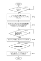
- FIG. 4 is a flowchart showing details of the stop control processing procedure executed by the stop control processing unit 34. Before the execution of this process, the main injector 5, the main throttle valve 6, the reforming throttle valve 15, and the reforming injector 16 are in an open state.
- the stop control processing unit 34 first determines whether or not the ignition switch 30 has been turned off based on the operation signal of the ignition switch 30 (procedure S111).
- the stop control processing unit 34 determines that the ignition switch 30 has not been turned off (procedure S111: NO)
- the stop control processing unit 34 executes the procedure S111 again.
- the stop control processing unit 34 determines that the ignition switch 30 has been turned off (procedure S111: YES)
- the stop control processing unit 34 controls the opening degrees of the main injector 5 and the main throttle valve 6 so that the ammonia engine 2 is idle. (Procedure S112). Specifically, the stop control processing unit 34 opens the main injector 5 and the main throttle valve 6 so that the amount of ammonia gas and air supplied to the ammonia engine 2 corresponds to the idle state of the ammonia engine 2. To control.
- the stop control processing unit 34 controls the opening degree of the reforming injector 16 and the reforming throttle valve 15 so as to reduce the supply amount of ammonia gas and air to the reformer 13 (procedure S113). As a result, the temperature of the reforming catalyst 13b of the reformer 13 is lowered. At this time, the amount of ammonia gas and air supplied to the reformer 13 is set so that the ammonia gas becomes rich with respect to air. As a result, the reformer 13 can be maintained in a reducing atmosphere.
- the stop control processing unit 34 determines whether or not the temperature of the reformer 13 is equal to or lower than the specified temperature (procedure S114).
- the specified temperature is a temperature at which oxidative deterioration of the reforming catalyst 13b does not proceed, for example, about 200 ° C.
- Step S114: NO When the stop control processing unit 34 determines that the temperature of the reformer 13 is higher than the specified temperature (procedure S114: NO), the stop control processing unit 34 executes the procedure S114 again.
- Step S114: YES controls the reforming injector 16 to be closed and the reforming throttle valve to be opened (procedure S115).
- the stop control processing unit 34 completely closes, for example, the reforming injector 16. As a result, the injection of the ammonia gas from the reforming injector 16 is stopped, so that the ammonia gas is not supplied to the reformer 13.
- the stop control processing unit 34 determines whether or not the specified time has elapsed since the control for closing the reforming injector 16 was performed (procedure S116).
- the specified time is, for example, a time during which all the gas in the reforming path 26 is replaced with air (fresh air).
- the specified time can be calculated from the number of revolutions of the ammonia engine 2 in the idle state (idle revolutions), the displacement of the ammonia engine 2, the volume of the reforming path 26, and the like.
- the idle rotation speed may be adjusted and determined in advance, or may be detected by the rotation speed sensor 29.
- the stop control processing unit 34 determines that the specified time has not elapsed (procedure S116: NO)
- the stop control processing unit 34 executes the procedure S116 again.
- the stop control processing unit 34 determines that the specified time has elapsed after the control processing of procedures S114 to S115 by the stop control processing unit 34 is executed (procedure S116: YES)
- the main injector 5 and the main throttle valve 6 and the modified throttle valve 15 are controlled to be closed (procedure S117).
- the stop control processing unit 34 fully closes, for example, the main injector 5, the main throttle valve 6, and the reforming throttle valve 15. As a result, the ammonia engine 2 is stopped.
- the catalyst temperature control unit 35 executes steps S111 to 113.
- the purge control unit 36 executes steps S114 and S115.
- the engine stop control unit 37 executes steps S116 and S117.
- the heating element 24 of the electric heater 17 is energized and the heating element 24 generates heat.
- the reforming injector 16 opens, ammonia gas is injected from the reforming injector 16 and the ammonia gas is supplied to the reformer 13.
- the ammonia gas is heated by the heat of the heating element 24, and the heat of the warmed ammonia gas is transferred to the reformer 13, so that the reformer 13 raises the temperature.
- the reforming throttle valve 15 is opened, air is supplied to the reformer 13.
- the ammonia engine 2 is started by the starter motor 31. Then, when the main throttle valve 6 and the main injector 5 are opened, air is supplied to the combustion chamber 2a of the ammonia engine 2, and ammonia gas is injected from the main injector 5 to the combustion chamber 2a of the ammonia engine 2. Ammonia gas is supplied. As a result, the ammonia gas begins to burn in the combustion chamber 2a.
- the reforming catalyst 13b of the reformer 13 starts reforming the ammonia gas and contains hydrogen. Reform gas is generated. Specifically, as shown in the following formula, a reforming reaction occurs in which ammonia is decomposed into hydrogen and nitrogen by the heat of combustion of ammonia, and a reforming gas containing hydrogen and nitrogen is generated. The reforming gas flows through the reforming gas flow path 18 and is supplied to the combustion chamber 2a of the ammonia engine 2. NH 3 ⁇ 3 / 2H 2 + 1 / 2N 2- Q
- the ammonia gas burns together with the hydrogen in the reforming gas in the combustion chamber 2a.
- the engine system 1 is in steady operation after the warming up of the reformer 13 is completed.
- the ammonia engine 2 is first idle, and the amount of ammonia gas and air supplied to the reformer 13 is further reduced. As a result, the temperature of the reforming catalyst 13b of the reformer 13 decreases.
- the reforming injector 16 closes, so that the injection of ammonia gas from the reforming injector 16 is stopped and the ammonia gas is not supplied to the reformer 13. Therefore, since only air is supplied to the reformer 13, the inside of the reforming path 26 is purged (scavenged) by air.
- the reforming throttle valve 15 closes, so that the supply of air to the reformer 13 is stopped. Further, when the main injector 5 and the main throttle valve 6 are closed, the supply of air to the combustion chamber 2a of the ammonia engine 2 is stopped, and the injection of ammonia gas from the main injector 5 is stopped, so that the ammonia engine 2 is stopped. The supply of ammonia gas to the combustion chamber 2a is stopped. As a result, the ammonia engine 2 coasts several times before stopping.
- the reforming injector 16 is controlled to be closed and the reforming throttle valve 15 is controlled to be opened. Since almost only air flows inside the reforming path 26, which is the quality vessel 13 and the reforming gas flow path 18, the inside of the reforming path 26 is purged by air. Further, by controlling the main injector 5 to be closed after being instructed to stop the ammonia engine 2, the supply of ammonia gas to the ammonia engine 2 is stopped, and the ammonia engine 2 is stopped. In this way, when the ammonia engine 2 is stopped, the inside of the reforming path 26 is purged, so that water vapor (H 2 O) does not exist in the reforming path 26. This prevents the condensation of water vapor remaining in the reforming path 26.
- H 2 O water vapor
- the function of the reforming catalyst 13b deteriorates due to the submersion of the reforming catalyst 13b of the reformer 13, the reforming path 26 is blocked due to freezing of water under the freezing point condition, and the ammonia gas dissolves in water in the reforming path 26. It is possible to prevent problems such as alikari corrosion due to the generation of strongly alkaline ammonia water and strong acid corrosion due to the formation of HNO 3 by dissolving NOx in water in the reforming path 26.
- the reaction activity of the reforming catalyst 13b is lowered at the next start of the ammonia engine 2, and the starting time becomes long.
- the starting time of the ammonia engine 2 is shortened.
- the supply of ammonia gas to the reformer 13 is stopped, so that the inside of the reforming path 26 is purged by air.
- the supply of ammonia gas and air to the ammonia engine 2 is stopped, and the supply of air to the reformer 13 is stopped, so that the ammonia engine 2 is stopped. Since the ammonia engine 2 is stopped after the inside of the reforming path 26 is purged in this way, the driver of the vehicle does not feel a sense of discomfort, and the condensation of the water vapor remaining in the reforming path 26 is prevented.
- the amount of ammonia gas passing through the reformer 13 is reduced. This makes it possible to reduce the size of the device that performs post-treatment of ammonia gas. Further, by reducing the supply amount of ammonia gas and air to the reformer 13 before purging in the reforming path 26, the temperature of the reforming catalyst 13b of the reformer 13 decreases. It is possible to prevent oxidative deterioration of the quality catalyst 13b.
- the ammonia engine 2 can be stopped in a state where the gas in the reforming path 26 is replaced with air (fresh air).
- the stop control processing unit 34 controls the reforming injector 16 to be fully closed in the procedure S115, but the opening degree of the reforming injector 16 is particularly set to the fully closed state. Not limited.
- the stop control processing unit 34 may close the reforming injector 16 to an opening degree such that a small amount of ammonia gas flows in the reforming path 26 so that water vapor (H 2 O) is not generated.
- the stop control processing unit 34 is not particularly limited to fully closed as long as it controls to close the main injector 5, the main throttle valve 6, and the reforming throttle valve 15.
- the purge control unit 36 controls to close the reforming injector 16 and controls to open the reforming throttle valve 15 so as to purge the inside of the reforming path 26. It is controlled, but it is not particularly limited to that form.
- the purge control unit 36 may be controlled to purge the inside of the reforming path 26 by controlling the reforming throttle valve 15 to be closed and the reforming injector 16 to be opened. In this case, since the supply of air to the reformer 13 is stopped, the inside of the reforming path 26 is purged with almost only ammonia gas.
- FIG. 5 is a block diagram showing a configuration of a control system of an engine system according to a second embodiment of the present invention.
- the control unit 32 of the engine system 1 of the present embodiment has a stop control processing unit 34A instead of the stop control processing unit 34 of the first embodiment described above.
- the stop control processing unit 34A includes the catalyst temperature control unit 35, a purge control unit 36A, and an engine stop control unit 37A.
- the engine stop control unit 37A defines the temperature of the reformer 13 detected by the temperature sensor 28 after the ignition switch 30 instructs the ignition switch 30 to stop the ammonia engine 2 and the catalyst temperature control unit 35 executes the control process. When the temperature drops below the temperature, the main injector 5 and the modified injector 16 are controlled to be closed.
- the purge control unit 36A controls to close the reforming injector 16 and controls to open the main throttle valve 6 and the reforming throttle valve 15 after the control process by the engine stop control unit 37A is executed. Further, the purge control unit 36A controls the main throttle valve 6 and the reforming throttle valve 15 to open, and controls the starter motor 31 so as to crank the ammonia engine 2 by a predetermined number of revolutions.
- FIG. 6 is a flowchart showing details of the control processing procedure executed by the stop control processing unit 34A. Before the execution of this process, the main injector 5, the main throttle valve 6, the reforming throttle valve 15, and the reforming injector 16 are in an open state.
- the stop control processing unit 34A sequentially executes the procedures S111 to S114 in the same manner as the stop control processing unit 34 in the first embodiment described above. After the control processing of steps 111 to 113 is executed by the stop control processing unit 34A, the stop control processing unit 34A determines that the temperature of the injector 13 detected by the temperature sensor 28 in step S114 is equal to or lower than the specified temperature. When this is done (procedure S114: YES), the main injector 5, the main throttle valve 6, the reforming injector 16 and the reforming throttle valve 15 are controlled to be closed (procedure S121). At this time, the stop control processing unit 34A fully closes, for example, the main injector 5, the main throttle valve 6, the reforming injector 16, and the reforming throttle valve 15. As a result, the supply of ammonia gas and air to the ammonia engine 2 and the reformer 13 is stopped.
- the stop control processing unit 34A determines whether or not a predetermined time has elapsed after controlling the main injector 5, the main throttle valve 6, the reforming injector 16 and the reforming throttle valve 15 to be closed (procedure S122). ).
- the stop control processing unit 34A determines that the specified time has not elapsed (procedure S122: NO)
- the stop control processing unit 34A executes the procedure S122 again.
- the stop control processing unit 34A determines that the specified time has elapsed (procedure S122: YES)
- the stop control processing unit 34A controls (keeps the reforming injector 16 closed) and modifies the main throttle valve 6 and the reforming.
- the throttle valve 15 is controlled to be opened (procedure S123). As a result, air is supplied to the ammonia engine 2 and the reformer 13.
- the stop control processing unit 34A controls the starter motor 31 so as to crank the ammonia engine 2 by a predetermined rotation speed (procedure S124).
- the specified rotation speed is a rotation speed at which the gas in the reforming path 26 is replaced by air (fresh air), and can be calculated from the displacement of the ammonia engine 2 and the volume of the reforming path 26. For example, when the displacement of the ammonia engine 2 is 1 L and the volume of the reforming path 26 is 3 L, the number of revolutions is 6 or more.
- the stop control processing unit 34A controls to close the main throttle valve 6 and the reforming throttle valve 15 (procedure S125). At this time, the stop control processing unit 34A fully closes, for example, the main throttle valve 6 and the reforming throttle valve 15. As a result, the supply of air to the ammonia engine 2 and the reformer 13 is stopped.
- the engine stop control unit 37A executes the procedures S114 and S121.
- the purge control unit 36A executes steps S122 to S125.
- the main injector 5, the main throttle valve 6, the reforming injector 16 and the reforming throttle valve 15 are closed, so that the combustion chamber 2a and the reformer of the ammonia engine 2 are closed. Ammonia gas and air are not supplied to 13. Therefore, the ammonia engine 2 rotates by inertia.
- the supply of ammonia gas to the ammonia engine 2 is stopped, so that the ammonia engine 2 is stopped after several rotations due to inertia.
- the inside of the reforming path 26 is purged by the air (fresh air). In this case, the engine rotation when the ammonia engine 2 is stopped is stabilized, and the condensation of water vapor remaining in the reforming path 26 is prevented.
- air is supplied to the ammonia engine 2 and the reformer 13, and the ammonia engine 2 cranks by a predetermined number of revolutions, so that purging in the reforming path 26 by air is stably performed. Will be.
- the main throttle valve 6 and the reforming throttle valve 15 are temporarily closed, and then the main throttle valve 6 and the reforming throttle valve 15 are opened.
- the form is not particularly limited, and even if the temperature of the reformer 13 drops to a specified temperature, the main throttle valve 6 and the reforming throttle valve 15 may be left open.
- the main throttle valve 6 and the reforming throttle valve 15 are controlled to open, and the ammonia engine 2 is cranked by a specified number of revolutions, but the present invention is not particularly limited to that form, and ammonia. If purging in the reforming path 26 is possible by coasting rotation of the ammonia engine 2 due to the suspension of supply of ammonia gas and air to the engine 2, the ammonia engine 2 does not have to be cranked.
- the stop control processing unit 34A controls the reforming injector 16 to be fully closed in the procedure S121, but the opening degree of the reforming injector 16 is particularly set to the fully closed state. Not limited.
- the stop control processing unit 34A may close the reforming injector 16 to an opening degree such that a small amount of ammonia gas flows in the reforming path 26 so that water vapor (H 2 O) is not generated.
- stop control processing unit 34A controls to close the main injector 5, the main throttle valve 6 and the reforming throttle valve 15 in the procedures S121 and 125, the stop control processing unit 34A is not particularly limited to fully closed.
- FIG. 7 is a schematic configuration diagram showing an engine system according to a third embodiment of the present invention.
- the exhaust gas purification catalyst 8 has a three-way catalyst 8a and an SCR catalyst 8b.
- the three-way catalyst 8a is a catalyst that oxidizes and removes ammonia remaining in the exhaust passage 4.
- the SCR catalyst 8b is arranged on the downstream side of the three-way catalyst 8a in the exhaust passage 4.
- the SCR catalyst 8b is a selective reduction catalyst that reduces nitrogen oxides (NOx) contained in exhaust gas to nitrogen (N 2 ) by ammonia.
- the SCR catalyst 8b is also a catalyst that collects and removes ammonia that has passed through the three-way catalyst 3a.
- the SCR catalyst 8b collects ammonia by physically adsorbing ammonia with an adsorbent such as zeolite.
- the engine system 1 includes a stop valve 20 arranged in the reforming gas flow path 18.
- the stop valve 20 is arranged between the reformed gas cooler 19 and the intake passage 3 in the reformed gas flow path 18.
- the stop valve 20 is an electromagnetic on-off valve that opens and closes the reforming gas flow path 18.
- the stop valve 20 is controlled by the control unit 32. When the ammonia engine 2 is started, the stop valve 20 is opened.
- control unit 32 has a stop control processing unit 34B instead of the stop control processing unit 34 in the first embodiment described above.
- the stop control processing unit 34B includes the catalyst temperature control unit 35, a purge control unit 36B, and an engine stop control unit 37B.
- the purge control unit 36B is instructed to stop the ammonia engine 2 by the ignition switch 30, and after the control process by the catalyst temperature control unit 35 is executed, the temperature of the reformer 13 detected by the temperature sensor 28 is the specified temperature.
- the main throttle valve 6 and the reforming throttle valve 15 are controlled to be closed, and the reforming injector 16 is controlled to be opened.
- the engine stop control unit 37B controls to close the main injector 5 and the reforming injector 16 after the control process by the purge control unit 36B is executed. Further, the engine stop control unit 37B controls to close the main injector 5 and the reforming injector 16, and then controls to close the stop valve 20 and also controls to open the main throttle valve 6.
- FIG. 9 is a flowchart showing details of the control processing procedure executed by the stop control processing unit 34B. Before the execution of this process, the main injector 5, the main throttle valve 6, the reforming throttle valve 15, the reforming injector 16 and the stop valve 20 are in an open state.
- the stop control processing unit 34B sequentially executes the procedures S111 to S114 in the same manner as the stop control processing unit 34 in the first embodiment described above.
- the stop control processing unit 34B determines that the temperature of the reformer 13 detected by the temperature sensor 28 in step S114 is equal to or lower than the specified temperature (procedure S114: YES)
- the main throttle valve 6 and the reforming throttle valve 15 is controlled to be closed, and the reforming injector 16 is controlled to be opened. (Procedure S131).
- the stop control processing unit 34B fully closes, for example, the reforming throttle valve 15 and the main throttle valve 6. As a result, the supply of air to the ammonia engine 2 and the reformer 13 is stopped.
- the stop control processing unit 34B controls the starter motor 31 so as to crank the ammonia engine 2 by a predetermined number of revolutions (procedure S132).
- the specified rotation speed is a rotation speed at which the gas in the reforming path 26 is replaced by ammonia gas, and can be calculated from the displacement of the ammonia engine 2, the volume of the reforming path 26, and the like.
- the stop control processing unit 34B controls the main injector 5 and the reforming injector 16 to be closed (procedure S133). At this time, the stop control processing unit 34B completely closes, for example, the main injector 5 and the modified injector 16. As a result, the supply of ammonia gas to the ammonia engine 2 and the reformer 13 is stopped.
- the stop control processing unit 34B controls to close the stop valve 20 and controls to open the main throttle valve 6 (procedure S134). As a result, air is supplied to the ammonia engine 2.
- the stop control processing unit 34B determines whether or not the specified time has elapsed after controlling the main throttle valve 6 to open (procedure S135).
- the stop control processing unit 34B executes the procedure S135 again.
- the stop control processing unit 34B controls to close the main throttle valve 6 (procedure S136). At this time, the stop control processing unit 34B closes the main throttle valve 6 fully, for example. As a result, the supply of air to the ammonia engine 2 is stopped.
- the purge control unit 36B executes the procedures S114, S131, and S132.
- the engine stop control unit 37B executes steps S133 to S136.
- the main throttle valve 6 and the reforming throttle valve 15 are closed, so that air is not supplied to the combustion chamber 2a and the reformer 13 of the ammonia engine 2. Then, the starter motor 31 cranks the ammonia engine 2 by a predetermined number of revolutions. As a result, the inside of the reforming path 26 is purged with ammonia gas.
- the ammonia gas discharged from the ammonia engine 2 is physically adsorbed on the adsorbent of the SCR catalyst 8b.
- the amount of the adsorbent is set so that the amount of ammonia gas discharged is within the range that can be adsorbed by the adsorbent. This makes it possible to prevent the leakage of ammonia gas to the outside of the system.
- the supply of air to the ammonia engine 2 and the reformer 13 is stopped, so that the inside of the reforming path 26 is purged by the ammonia gas.
- the supply of ammonia gas to the ammonia engine 2 and the reformer 13 is stopped, so that the ammonia engine 2 is stopped. Since the ammonia engine 2 is stopped after the inside of the reforming path 26 is purged in this way, the driver of the vehicle does not feel a sense of discomfort, and the condensation of the water vapor remaining in the reforming path 26 is prevented.
- air is supplied to the ammonia engine 2 after the purging in the reforming path 26 by the ammonia gas is completed. Therefore, due to the extra rotation when the ammonia engine 2 is stopped, the ammonia existing between the stop valve 20 and the ammonia engine 2 is purged by air. This makes it possible to prevent offensive odors in the intake passage 3 and the reformed gas flow path 18 caused by ammonia gas.
- the main throttle valve 6 and the modified throttle valve 15 are controlled to be closed, and the ammonia engine 2 is cranked by a specified number of revolutions.
- the present embodiment is not particularly limited to ammonia. If purging in the reforming path 26 is possible by coasting rotation of the ammonia engine 2 due to the suspension of air supply to the engine 2, the ammonia engine 2 does not have to be cranked.
- the stop control processing unit 34B controls in steps S131, S133, and S136 to close the main throttle valve 6, the reforming throttle valve 15, the main injector 5, and the reforming injector 16. , Especially not limited to fully closed.
- the present invention is not limited to the above embodiments.
- the stop valve 20 may be arranged in the reforming gas flow path 18 as in the third embodiment.
- a plurality of main injectors 5 for injecting ammonia gas into each combustion chamber 2a of the ammonia engine 2 are attached to the ammonia engine 2, but the number of main injectors 5 is one. May be good.
- the main injector 5 may be arranged so as to inject ammonia gas between the main throttle valve 6 in the intake passage 3 and the ammonia engine 2, or the main throttle valve 6 in the intake passage 3. It may be arranged so as to inject ammonia gas on the upstream side of the valve.
- the electric heater 17 heats the ammonia gas supplied to the reformer 13 to raise the temperature of the reformer 13 through the ammonia gas, but the temperature is particularly limited to that form. Absent.
- the electric heater 17 may directly raise the temperature of the reformer 13 by directly heating the reformer 13. Further, a combustion type heater that burns and heats ammonia may be used.
- the temperature of the reformer 13 is detected by the temperature sensor 28, but the present invention is not particularly limited to that mode, and the reformer 13 is based on the flow rate of ammonia gas, the flow rate of air, the time, the room temperature, and the like. You may estimate the temperature of.
- the air flow path 14 through which the air supplied to the reformer 13 flows is branched and connected to the intake passage 3, but the present invention is not particularly limited to that form, and the intake air connected to the ammonia engine 2 is connected. Air may be supplied to the air flow path 14 from a path different from the passage 3. In this case, it is possible to prevent the influence of the pulsation of the intake passage 3.
- the reforming injector 16 for injecting ammonia gas toward the reformer 13 is connected to the ammonia gas flow path 21, but the embodiment is not particularly limited, and for example, the reforming injector.
- a flow rate adjusting valve may be used instead of 16.
- the other end of the ammonia gas flow path 21 is connected to the air flow path 14, and a flow rate adjusting valve (fuel supply valve) is provided in the ammonia gas flow path 21.
- the other end of the reformed gas flow path 18 is connected to the intake passage 3, but the embodiment is not particularly limited, and for example, the ammonia engine 2 is connected to the other end of the reformed gas flow path 18.
- an injector may be provided to inject the reforming gas toward the intake passage 3.
- ammonia is used as the fuel supplied to the ammonia engine 2 and the reformer 13, but the fuel used is not particularly limited to ammonia, for example, an alcohol-based substance such as ethanol or the like. It may be.
- the engine system of the above embodiment is mounted on an engine type vehicle
- the present invention can be applied to, for example, a high lid type vehicle.
Landscapes
- Engineering & Computer Science (AREA)
- Chemical & Material Sciences (AREA)
- Combustion & Propulsion (AREA)
- Mechanical Engineering (AREA)
- General Engineering & Computer Science (AREA)
- Chemical Kinetics & Catalysis (AREA)
- Oil, Petroleum & Natural Gas (AREA)
- General Chemical & Material Sciences (AREA)
- Health & Medical Sciences (AREA)
- Organic Chemistry (AREA)
- Toxicology (AREA)
- Inorganic Chemistry (AREA)
- Materials Engineering (AREA)
- General Health & Medical Sciences (AREA)
- Output Control And Ontrol Of Special Type Engine (AREA)
- Control Of Throttle Valves Provided In The Intake System Or In The Exhaust System (AREA)
- Electrical Control Of Air Or Fuel Supplied To Internal-Combustion Engine (AREA)
- Exhaust Gas After Treatment (AREA)
Abstract
Priority Applications (3)
| Application Number | Priority Date | Filing Date | Title |
|---|---|---|---|
| CN202080038709.4A CN113874609B (zh) | 2019-05-29 | 2020-05-26 | 发动机系统 |
| US17/606,521 US11578686B2 (en) | 2019-05-29 | 2020-05-26 | Engine system |
| AU2020283012A AU2020283012B2 (en) | 2019-05-29 | 2020-05-26 | Engine system |
Applications Claiming Priority (4)
| Application Number | Priority Date | Filing Date | Title |
|---|---|---|---|
| JP2019100515 | 2019-05-29 | ||
| JP2019-100515 | 2019-05-29 | ||
| JP2020049661A JP7342754B2 (ja) | 2019-05-29 | 2020-03-19 | エンジンシステム |
| JP2020-049661 | 2020-03-19 |
Publications (1)
| Publication Number | Publication Date |
|---|---|
| WO2020241604A1 true WO2020241604A1 (fr) | 2020-12-03 |
Family
ID=73552732
Family Applications (1)
| Application Number | Title | Priority Date | Filing Date |
|---|---|---|---|
| PCT/JP2020/020640 Ceased WO2020241604A1 (fr) | 2019-05-29 | 2020-05-26 | Système de moteur |
Country Status (3)
| Country | Link |
|---|---|
| US (1) | US11578686B2 (fr) |
| CN (1) | CN113874609B (fr) |
| WO (1) | WO2020241604A1 (fr) |
Cited By (5)
| Publication number | Priority date | Publication date | Assignee | Title |
|---|---|---|---|---|
| US20220170415A1 (en) * | 2019-03-26 | 2022-06-02 | Kabushiki Kaisha Toyota Jidoshokki | Engine system |
| EP4413246A1 (fr) * | 2021-10-08 | 2024-08-14 | Alfa Laval Corporate AB | Agencement pour préparer un combustible à base d'ammoniac gazeux devant être brûlé dans une chaudière et procédé associé |
| JP2025512105A (ja) * | 2022-06-20 | 2025-04-16 | ジョンソン、マッセイ、パブリック、リミテッド、カンパニー | アンモニアの分解方法 |
| US20260015228A1 (en) * | 2023-09-01 | 2026-01-15 | First Ammonia Motors, Inc. | Systems and methods for phase-safe ammonia vapor fuel delivery to an internal combustion engine |
| US12617673B2 (en) * | 2025-09-22 | 2026-05-05 | First Ammonia Motors, Inc. | Systems and methods for phase-safe ammonia vapor fuel delivery to an internal combustion engine |
Families Citing this family (20)
| Publication number | Priority date | Publication date | Assignee | Title |
|---|---|---|---|---|
| US11724245B2 (en) | 2021-08-13 | 2023-08-15 | Amogy Inc. | Integrated heat exchanger reactors for renewable fuel delivery systems |
| US11994061B2 (en) | 2021-05-14 | 2024-05-28 | Amogy Inc. | Methods for reforming ammonia |
| JP2024521417A (ja) | 2021-06-11 | 2024-05-31 | アモジー インコーポレイテッド | アンモニアを処理するためのシステムおよび方法 |
| US11539063B1 (en) | 2021-08-17 | 2022-12-27 | Amogy Inc. | Systems and methods for processing hydrogen |
| JP2024009392A (ja) * | 2022-07-11 | 2024-01-23 | ヤンマーホールディングス株式会社 | アンモニア分解システム、内燃機関システム及びアンモニア分解方法 |
| US12358787B2 (en) | 2022-08-06 | 2025-07-15 | First Ammonia Motors, Inc. | Systems and methods for an internal combustion engine utilizing ammonia as a fuel source and as a heat-exchange medium for engine cooling |
| US12435686B2 (en) | 2022-08-06 | 2025-10-07 | First Ammonia Motors, Inc. | Systems and methods for the on-board production of hydrogen from ammonia for fueling an internal combustion engine that requires no fossil fuel promotor |
| US12371319B2 (en) | 2022-08-06 | 2025-07-29 | First Ammonia Motors, Inc. | Systems and methods for cooling hydrogen fuel generated on-board prior to injection into an internal combustion engine |
| US11834334B1 (en) | 2022-10-06 | 2023-12-05 | Amogy Inc. | Systems and methods of processing ammonia |
| JP7834005B2 (ja) * | 2022-10-13 | 2026-03-23 | 株式会社豊田自動織機 | エンジンシステム |
| US11866328B1 (en) | 2022-10-21 | 2024-01-09 | Amogy Inc. | Systems and methods for processing ammonia |
| US11795055B1 (en) | 2022-10-21 | 2023-10-24 | Amogy Inc. | Systems and methods for processing ammonia |
| CN116122973B (zh) * | 2023-02-09 | 2025-06-03 | 哈尔滨工程大学 | 柴油、氨双燃料发动机及混合气活性改制与高效燃烧方法 |
| CN116220958B (zh) * | 2023-02-15 | 2026-04-24 | 四川铭衡科技有限公司 | 一种基于重整机制的氨氢发动机 |
| CN116357481B (zh) * | 2023-03-28 | 2025-02-11 | 哈尔滨工程大学 | 基于液氨热管理供给系统的氨氢燃料发动机及运行控制方法 |
| US12442324B1 (en) | 2023-09-01 | 2025-10-14 | First Ammonia Motors, Inc. | Systems and methods for supplementing an ammonia heat-exchange unit for engine cooling with a radiator |
| US12552419B2 (en) * | 2023-10-31 | 2026-02-17 | Cummins Power Generation Inc. | Ammonia cracking for multi-fuel engines |
| CH721501A1 (de) * | 2024-01-10 | 2025-07-31 | Liebherr Machines Bulle Sa | Verbrennungskraftmaschine mit Vorrichtung zur Spülung eines Strömungspfades sowie Verfahren zum Betrieb einer solchen Verbrennungskraftmaschine |
| CN118223971B (zh) * | 2024-04-08 | 2026-02-24 | 潍柴动力股份有限公司 | 一种发动机的热管理系统 |
| CN118775108B (zh) * | 2024-09-10 | 2024-11-12 | 烟台哈尔滨工程大学研究院 | 一种船用氨裂解制氢发动机系统及控制方法 |
Citations (2)
| Publication number | Priority date | Publication date | Assignee | Title |
|---|---|---|---|---|
| WO2012090739A1 (fr) * | 2010-12-30 | 2012-07-05 | 株式会社豊田中央研究所 | Générateur d'hydrogène et moteur à combustion interne équipé d'un générateur d'hydrogène |
| JP2014211155A (ja) * | 2013-04-19 | 2014-11-13 | 株式会社豊田中央研究所 | 内燃機関 |
Family Cites Families (43)
| Publication number | Priority date | Publication date | Assignee | Title |
|---|---|---|---|---|
| US4131086A (en) * | 1974-07-20 | 1978-12-26 | Nippon Soken, Inc. | Fuel reforming apparatus for use with internal combustion engine |
| US4478177A (en) * | 1980-06-30 | 1984-10-23 | Valdespino Joseph M | Internal combustion engine |
| US4480595A (en) * | 1982-01-18 | 1984-11-06 | Hobby William M | Internal combustion engine |
| US4416224A (en) * | 1982-01-18 | 1983-11-22 | Hobby William M | Internal combustion engine |
| US6715452B1 (en) * | 2002-11-13 | 2004-04-06 | Arvin Technologies, Inc. | Method and apparatus for shutting down a fuel reformer |
| JP4251321B2 (ja) * | 2003-01-28 | 2009-04-08 | トヨタ自動車株式会社 | 内燃機関および内燃機関の運転方法 |
| JP4038770B2 (ja) * | 2003-08-27 | 2008-01-30 | トヨタ自動車株式会社 | 改質器の状態判定装置および方法 |
| JP2006052662A (ja) * | 2004-08-10 | 2006-02-23 | Toyota Motor Corp | 内燃機関およびその運転方法 |
| JP4424153B2 (ja) * | 2004-10-22 | 2010-03-03 | トヨタ自動車株式会社 | 内燃機関装置および内燃機関の停止位置推定方法並びに内燃機関の制御方法 |
| JP2006118488A (ja) * | 2004-10-25 | 2006-05-11 | Toyota Motor Corp | 内燃機関 |
| JP2007187111A (ja) * | 2006-01-13 | 2007-07-26 | Toyota Motor Corp | 水素利用内燃機関 |
| US7771675B2 (en) * | 2006-02-06 | 2010-08-10 | Nissan Motor Co., Ltd. | Fuel supply device for internal combustion and control method therefor |
| JP4449956B2 (ja) * | 2006-08-04 | 2010-04-14 | トヨタ自動車株式会社 | 内燃機関 |
| JP2008063996A (ja) * | 2006-09-06 | 2008-03-21 | Toyota Motor Corp | 内燃機関 |
| JP2008267268A (ja) * | 2007-04-20 | 2008-11-06 | Nissan Motor Co Ltd | 内燃機関の燃料供給装置 |
| JP2009097425A (ja) * | 2007-10-17 | 2009-05-07 | Toyota Motor Corp | 燃料改質装置 |
| JP4274279B2 (ja) * | 2007-11-02 | 2009-06-03 | トヨタ自動車株式会社 | 内燃機関 |
| JP5018550B2 (ja) * | 2008-02-27 | 2012-09-05 | トヨタ自動車株式会社 | 燃料改質装置 |
| JP5049947B2 (ja) * | 2008-11-19 | 2012-10-17 | 日立造船株式会社 | アンモニアエンジンシステム |
| JP5352323B2 (ja) * | 2009-04-07 | 2013-11-27 | トヨタ自動車株式会社 | 水素生成装置及び水素生成方法 |
| DE102009040607A1 (de) | 2009-09-08 | 2011-03-10 | Schaeffler Technologies Gmbh & Co. Kg | Baueinheit für einen Ventiltrieb einer Brennkraftmaschine |
| US8151779B1 (en) * | 2010-03-25 | 2012-04-10 | Toyota Jidosha Kabushiki Kaisha | Control device of an internal combustion engine |
| US8245671B2 (en) * | 2010-04-08 | 2012-08-21 | Ford Global Technologies, Llc | Operating an engine with reformate |
| US8423265B2 (en) * | 2010-05-21 | 2013-04-16 | Toyota Jidosha Kabushiki Kaisha | Control system of internal combustion engine |
| US8464515B2 (en) * | 2010-05-21 | 2013-06-18 | Toyota Jidosha Kabushiki Kaisha | Ammonia burning internal combustion engine |
| US8370049B1 (en) * | 2010-05-21 | 2013-02-05 | Toyota Jidosha Kabushiki Kaisha | Control system of internal combustion engine |
| JP2012066945A (ja) * | 2010-09-21 | 2012-04-05 | Hitachi Zosen Corp | アンモニアからの水素の製造方法 |
| JP5764984B2 (ja) * | 2011-03-09 | 2015-08-19 | 日産自動車株式会社 | 内燃機関システム |
| JP2013029039A (ja) * | 2011-07-27 | 2013-02-07 | Denso Corp | 燃料供給システム |
| JP2013234079A (ja) * | 2012-05-07 | 2013-11-21 | Toyota Industries Corp | 水素発生装置 |
| JP5862443B2 (ja) * | 2012-05-10 | 2016-02-16 | 株式会社デンソー | 燃料気化器 |
| JP5886497B2 (ja) * | 2012-05-14 | 2016-03-16 | 株式会社豊田自動織機 | 改質システム |
| JP2013237581A (ja) * | 2012-05-14 | 2013-11-28 | Toyota Industries Corp | 改質システム |
| US8904765B2 (en) * | 2013-04-19 | 2014-12-09 | Kabushiki Kaisha Toyota Chuo Kenkyusho | Internal combustion engine |
| JP6217269B2 (ja) * | 2013-09-13 | 2017-10-25 | 株式会社デンソー | 内燃機関の燃料改質装置 |
| JP6258779B2 (ja) * | 2014-05-16 | 2018-01-10 | 株式会社Soken | 燃料供給システム |
| JP2016130186A (ja) * | 2015-01-13 | 2016-07-21 | 株式会社デンソー | 燃料改質装置 |
| US9925975B2 (en) * | 2016-05-04 | 2018-03-27 | Ford Global Technologies, Llc | Method and system for hybrid vehicle control |
| JP6639342B2 (ja) * | 2016-07-14 | 2020-02-05 | ヤンマー株式会社 | 内燃機関の制御装置および内燃機関の制御方法 |
| JP6639341B2 (ja) * | 2016-07-14 | 2020-02-05 | ヤンマー株式会社 | 内燃機関の制御装置および内燃機関の制御方法 |
| JP6639345B2 (ja) * | 2016-07-14 | 2020-02-05 | ヤンマー株式会社 | 内燃機関の制御装置および内燃機関の制御方法 |
| JP2018076214A (ja) * | 2016-11-11 | 2018-05-17 | 株式会社豊田自動織機 | 水素生成装置 |
| JP6624112B2 (ja) * | 2017-02-16 | 2019-12-25 | トヨタ自動車株式会社 | エンジンの制御装置 |
-
2020
- 2020-05-26 WO PCT/JP2020/020640 patent/WO2020241604A1/fr not_active Ceased
- 2020-05-26 CN CN202080038709.4A patent/CN113874609B/zh active Active
- 2020-05-26 US US17/606,521 patent/US11578686B2/en active Active
Patent Citations (2)
| Publication number | Priority date | Publication date | Assignee | Title |
|---|---|---|---|---|
| WO2012090739A1 (fr) * | 2010-12-30 | 2012-07-05 | 株式会社豊田中央研究所 | Générateur d'hydrogène et moteur à combustion interne équipé d'un générateur d'hydrogène |
| JP2014211155A (ja) * | 2013-04-19 | 2014-11-13 | 株式会社豊田中央研究所 | 内燃機関 |
Cited By (6)
| Publication number | Priority date | Publication date | Assignee | Title |
|---|---|---|---|---|
| US20220170415A1 (en) * | 2019-03-26 | 2022-06-02 | Kabushiki Kaisha Toyota Jidoshokki | Engine system |
| US11713727B2 (en) * | 2019-03-26 | 2023-08-01 | Kabushiki Kaisha Toyota Jidoshokki | Engine system |
| EP4413246A1 (fr) * | 2021-10-08 | 2024-08-14 | Alfa Laval Corporate AB | Agencement pour préparer un combustible à base d'ammoniac gazeux devant être brûlé dans une chaudière et procédé associé |
| JP2025512105A (ja) * | 2022-06-20 | 2025-04-16 | ジョンソン、マッセイ、パブリック、リミテッド、カンパニー | アンモニアの分解方法 |
| US20260015228A1 (en) * | 2023-09-01 | 2026-01-15 | First Ammonia Motors, Inc. | Systems and methods for phase-safe ammonia vapor fuel delivery to an internal combustion engine |
| US12617673B2 (en) * | 2025-09-22 | 2026-05-05 | First Ammonia Motors, Inc. | Systems and methods for phase-safe ammonia vapor fuel delivery to an internal combustion engine |
Also Published As
| Publication number | Publication date |
|---|---|
| US11578686B2 (en) | 2023-02-14 |
| US20220205415A1 (en) | 2022-06-30 |
| CN113874609B (zh) | 2023-06-20 |
| CN113874609A (zh) | 2021-12-31 |
Similar Documents
| Publication | Publication Date | Title |
|---|---|---|
| WO2020241604A1 (fr) | Système de moteur | |
| JP7151581B2 (ja) | エンジンシステム | |
| WO2020208875A1 (fr) | Système reformeur et système de moteur | |
| WO2021049287A1 (fr) | Système de moteur | |
| JP2020196646A (ja) | 改質システム | |
| JP2020147475A (ja) | 改質システム | |
| JP7342754B2 (ja) | エンジンシステム | |
| JP4842979B2 (ja) | 排気浄化装置 | |
| JP6052257B2 (ja) | 還元剤添加装置 | |
| JP2021071253A (ja) | 燃焼システム | |
| JP7816040B2 (ja) | アンモニアエンジンシステム | |
| JP4720667B2 (ja) | 内燃機関の蒸発燃料処理装置 | |
| JP2020159241A (ja) | エンジンシステム | |
| JP2004060564A (ja) | 内燃機関の排気ガス浄化装置 | |
| JP4103759B2 (ja) | 内燃機関の排気浄化装置 | |
| WO2020209021A1 (fr) | Moteur | |
| JP5018435B2 (ja) | 車両および内燃機関の制御方法 | |
| JP2024057726A (ja) | エンジンシステム | |
| JP7834005B2 (ja) | エンジンシステム | |
| JP2021070612A (ja) | 燃焼システム | |
| JP6455377B2 (ja) | 還元剤添加装置 | |
| JP2021181756A (ja) | 車両の触媒活性制御装置 | |
| JP2009091903A (ja) | 内燃機関の排気浄化装置 | |
| JPH0849528A (ja) | 触媒加熱装置 | |
| JP5409568B2 (ja) | 還元性気体供給装置 |
Legal Events
| Date | Code | Title | Description |
|---|---|---|---|
| 121 | Ep: the epo has been informed by wipo that ep was designated in this application |
Ref document number: 20813506 Country of ref document: EP Kind code of ref document: A1 |
|
| ENP | Entry into the national phase |
Ref document number: 2020283012 Country of ref document: AU Date of ref document: 20200526 Kind code of ref document: A |
|
| NENP | Non-entry into the national phase |
Ref country code: DE |
|
| 122 | Ep: pct application non-entry in european phase |
Ref document number: 20813506 Country of ref document: EP Kind code of ref document: A1 |