WO2020241865A1 - 原料液濃縮システム - Google Patents
原料液濃縮システム Download PDFInfo
- Publication number
- WO2020241865A1 WO2020241865A1 PCT/JP2020/021444 JP2020021444W WO2020241865A1 WO 2020241865 A1 WO2020241865 A1 WO 2020241865A1 JP 2020021444 W JP2020021444 W JP 2020021444W WO 2020241865 A1 WO2020241865 A1 WO 2020241865A1
- Authority
- WO
- WIPO (PCT)
- Prior art keywords
- raw material
- solution
- material liquid
- solvent
- induction
- Prior art date
- Legal status (The legal status is an assumption and is not a legal conclusion. Google has not performed a legal analysis and makes no representation as to the accuracy of the status listed.)
- Ceased
Links
Images


Classifications
-
- B—PERFORMING OPERATIONS; TRANSPORTING
- B01—PHYSICAL OR CHEMICAL PROCESSES OR APPARATUS IN GENERAL
- B01D—SEPARATION
- B01D61/00—Processes of separation using semi-permeable membranes, e.g. dialysis, osmosis or ultrafiltration; Apparatus, accessories or auxiliary operations specially adapted therefor
- B01D61/002—Forward osmosis or direct osmosis
-
- A—HUMAN NECESSITIES
- A61—MEDICAL OR VETERINARY SCIENCE; HYGIENE
- A61K—PREPARATIONS FOR MEDICAL, DENTAL OR TOILETRY PURPOSES
- A61K38/00—Medicinal preparations containing peptides
- A61K38/04—Peptides having up to 20 amino acids in a fully defined sequence; Derivatives thereof
- A61K38/05—Dipeptides
-
- B—PERFORMING OPERATIONS; TRANSPORTING
- B01—PHYSICAL OR CHEMICAL PROCESSES OR APPARATUS IN GENERAL
- B01D—SEPARATION
- B01D61/00—Processes of separation using semi-permeable membranes, e.g. dialysis, osmosis or ultrafiltration; Apparatus, accessories or auxiliary operations specially adapted therefor
- B01D61/002—Forward osmosis or direct osmosis
- B01D61/0023—Accessories; Auxiliary operations
-
- B—PERFORMING OPERATIONS; TRANSPORTING
- B01—PHYSICAL OR CHEMICAL PROCESSES OR APPARATUS IN GENERAL
- B01D—SEPARATION
- B01D61/00—Processes of separation using semi-permeable membranes, e.g. dialysis, osmosis or ultrafiltration; Apparatus, accessories or auxiliary operations specially adapted therefor
- B01D61/36—Pervaporation; Membrane distillation; Liquid permeation
- B01D61/364—Membrane distillation
-
- B—PERFORMING OPERATIONS; TRANSPORTING
- B01—PHYSICAL OR CHEMICAL PROCESSES OR APPARATUS IN GENERAL
- B01D—SEPARATION
- B01D61/00—Processes of separation using semi-permeable membranes, e.g. dialysis, osmosis or ultrafiltration; Apparatus, accessories or auxiliary operations specially adapted therefor
- B01D61/58—Multistep processes
-
- B—PERFORMING OPERATIONS; TRANSPORTING
- B01—PHYSICAL OR CHEMICAL PROCESSES OR APPARATUS IN GENERAL
- B01D—SEPARATION
- B01D63/00—Apparatus in general for separation processes using semi-permeable membranes
- B01D63/02—Hollow fibre modules
- B01D63/04—Hollow fibre modules comprising multiple hollow fibre assemblies
-
- B—PERFORMING OPERATIONS; TRANSPORTING
- B01—PHYSICAL OR CHEMICAL PROCESSES OR APPARATUS IN GENERAL
- B01D—SEPARATION
- B01D67/00—Processes specially adapted for manufacturing semi-permeable membranes for separation processes or apparatus
- B01D67/0002—Organic membrane manufacture
- B01D67/0006—Organic membrane manufacture by chemical reactions
-
- B—PERFORMING OPERATIONS; TRANSPORTING
- B01—PHYSICAL OR CHEMICAL PROCESSES OR APPARATUS IN GENERAL
- B01D—SEPARATION
- B01D69/00—Semi-permeable membranes for separation processes or apparatus characterised by their form, structure or properties; Manufacturing processes specially adapted therefor
- B01D69/02—Semi-permeable membranes for separation processes or apparatus characterised by their form, structure or properties; Manufacturing processes specially adapted therefor characterised by their properties
-
- B—PERFORMING OPERATIONS; TRANSPORTING
- B01—PHYSICAL OR CHEMICAL PROCESSES OR APPARATUS IN GENERAL
- B01D—SEPARATION
- B01D69/00—Semi-permeable membranes for separation processes or apparatus characterised by their form, structure or properties; Manufacturing processes specially adapted therefor
- B01D69/08—Hollow fibre membranes
- B01D69/087—Details relating to the spinning process
-
- B—PERFORMING OPERATIONS; TRANSPORTING
- B01—PHYSICAL OR CHEMICAL PROCESSES OR APPARATUS IN GENERAL
- B01D—SEPARATION
- B01D69/00—Semi-permeable membranes for separation processes or apparatus characterised by their form, structure or properties; Manufacturing processes specially adapted therefor
- B01D69/10—Supported membranes; Membrane supports
-
- B—PERFORMING OPERATIONS; TRANSPORTING
- B01—PHYSICAL OR CHEMICAL PROCESSES OR APPARATUS IN GENERAL
- B01D—SEPARATION
- B01D69/00—Semi-permeable membranes for separation processes or apparatus characterised by their form, structure or properties; Manufacturing processes specially adapted therefor
- B01D69/12—Composite membranes; Ultra-thin membranes
- B01D69/125—In situ manufacturing by polymerisation, polycondensation, cross-linking or chemical reaction
- B01D69/1251—In situ manufacturing by polymerisation, polycondensation, cross-linking or chemical reaction by interfacial polymerisation
-
- B—PERFORMING OPERATIONS; TRANSPORTING
- B01—PHYSICAL OR CHEMICAL PROCESSES OR APPARATUS IN GENERAL
- B01D—SEPARATION
- B01D71/00—Semi-permeable membranes for separation processes or apparatus characterised by the material; Manufacturing processes specially adapted therefor
- B01D71/06—Organic material
- B01D71/56—Polyamides, e.g. polyester-amides
-
- B—PERFORMING OPERATIONS; TRANSPORTING
- B01—PHYSICAL OR CHEMICAL PROCESSES OR APPARATUS IN GENERAL
- B01D—SEPARATION
- B01D71/00—Semi-permeable membranes for separation processes or apparatus characterised by the material; Manufacturing processes specially adapted therefor
- B01D71/06—Organic material
- B01D71/66—Polymers having sulfur in the main chain, with or without nitrogen, oxygen or carbon only
- B01D71/68—Polysulfones; Polyethersulfones
-
- B—PERFORMING OPERATIONS; TRANSPORTING
- B01—PHYSICAL OR CHEMICAL PROCESSES OR APPARATUS IN GENERAL
- B01D—SEPARATION
- B01D2323/00—Details relating to membrane preparation
- B01D2323/04—Hydrophobization
-
- B—PERFORMING OPERATIONS; TRANSPORTING
- B01—PHYSICAL OR CHEMICAL PROCESSES OR APPARATUS IN GENERAL
- B01D—SEPARATION
- B01D2323/00—Details relating to membrane preparation
- B01D2323/30—Cross-linking
Definitions
- the present invention relates to a raw material liquid concentration system for a pharmaceutical manufacturing process. Specifically, by separating a part of the solvent from the raw material liquid used for pharmaceutical purposes by the forward osmosis method and concentrating the raw material liquid, deterioration and decrease of the components in the raw material liquid are suppressed, and the raw material liquid is efficiently concentrated. Regarding a raw material solution concentration system that can be used.
- Proteins such as enzymes or peptides are widely used as diagnostic / test agents and pharmaceuticals. Since these raw materials are very expensive, it is important to recover them in high yield without denaturation in the manufacturing process.
- Ultrafiltration membranes are commonly used as one method for stably and efficiently extracting and purifying proteins.
- the ultrafiltration membrane is a technique for separating by sieving, and since it does not involve temperature changes, it is possible to reduce the energy load.
- proteins having a molecular weight of several thousand to several million are often fractionally purified by an ultrafiltration membrane. Although components larger than the molecular weight cut-off of the membrane are retained, water passes through the membrane and is effective for protein concentration and the like.
- RO Reverse Osmosis
- the raw material liquid is pressurized to a predetermined pressure higher than the osmotic pressure of the raw material liquid, then supplied to the RO membrane module, permeated through the RO membrane, and the solvent (typically water) in the raw material liquid is used. ) Is removed to concentrate the raw material liquid.
- Patent Document 1 since the ultrafiltration membrane requires pressurization of the raw material liquid, there is a problem that the solute contained in the raw material liquid adheres to the membrane surface and the recovery rate is lowered. Further, in the case of medium-molecular-weight drugs that are being developed these days, some of them have a molecular weight smaller than the fractional molecular weight of the ultrafiltration membrane, and the recovery rate is lowered because a part of the ultrafiltration membrane is permeated.
- Patent Document 2 since pressurization is required, the solute contained in the raw material liquid adheres to the surface of the RO film, and there is a problem that the recovery rate is lowered.
- the present invention is a raw material liquid concentrating system and a raw material liquid concentrating method capable of suppressing adhesion of raw material components to the film surface and increasing the recovery rate of the raw material components (more specifically, solutes in the raw material liquid) after concentration.
- the purpose is to provide.
- a raw material liquid concentration system for a pharmaceutical manufacturing process A forward osmosis membrane, and a forward osmosis membrane unit having a raw material liquid side space and an induction solution side space separated from each other by the forward osmosis membrane.
- a raw material liquid flow path for supplying a raw material liquid containing a solvent and a solute to the raw material liquid side space
- An induction solution flow path that supplies an induction solution containing an inducer to the induction solution side space
- a concentrate flow path for taking out the concentrated raw material solution from the forward osmosis membrane unit, and a dilution induction solution flow path for taking out the dilution induction solution from the forward osmosis membrane unit.
- the forward osmosis membrane is a concentrated raw material solution and a dilution inducing solution by moving the solvent in the raw material solution into the inducing solution and moving the inducing substance in the inducing solution into the raw material solution.
- a raw material solution concentration system [2] The raw material liquid concentrating system according to the first aspect, wherein the forward osmosis membrane is a hollow fiber membrane.
- a plurality of the hollow fiber membranes form a hollow fiber bundle.
- the hollow fiber membrane includes a microporous support membrane and a separation active layer which is a polymer polymer thin film provided on the inner surface of the microporous support membrane.
- the membrane area of the hollow fiber yarn bundle is 0.01 m 2 or more, and In a scanning electron microscope image obtained by photographing a cross section of the separation active layer in the thickness direction, the coefficient of variation of the thickness of the separation active layer in the radial direction and the length direction of the hollow fiber bundle is 0 to 60%.
- the raw material liquid concentration system according to the second aspect [4] The raw material liquid concentrating system according to the second or third aspect, wherein a pressure of 10 kPa or more and 200 kPa or less is applied from the inside to the outside of the hollow fiber membrane. [5] The raw material liquid concentration system according to any one of the above aspects 1 to 4, which is a cross-flow filtration method.
- the raw material liquid concentrating system according to any one of the above aspects 1 to 5, further comprising a raw material liquid temperature adjusting mechanism.
- the above embodiment further comprising a first induction solution regeneration unit that removes the solvent from the dilution induction solution to obtain a regeneration induction solution and supplies the obtained regeneration induction solution again as the induction solution.
- the raw material solution concentration system according to any one of 1 to 6.
- a second induction solution regeneration unit that removes the solvent from the induction solution to obtain a concentration induction solution, and supplies a mixture of the obtained concentration induction solution and the dilution induction solution as the induction solution.
- the raw material solution concentration system according to any one of the above aspects 1 to 8, further comprising.
- the positive permeation film is composed of polyethersulfone, polysulfone, polyketone, polyetheretherketone, polyphenylene ether, polyvinylidene fluoride, polyacrylonitrile, polyimine, polyimide, polybenzoxazole, polybenzoimidazole, sulfonated tetrafluoroethylene,
- the raw material liquid concentrating system according to any one of the above aspects 12 to 15, wherein the concentrated raw material liquid circulates at a circulation linear velocity of 0.03 cm / s or more and 15 cm / s or less.
- the initial permeation flux of the forward osmosis membrane is 0.1L / (m 2 ⁇ hr) or 50L / (m 2 ⁇ hr) or less, the raw material liquid concentrate according to any one of the above embodiments 12-16 system.
- a raw material solution containing a solvent and a solute and an inducing solution containing an inducing substance are brought into contact with each other via a forward osmosis membrane to move the solvent in the raw material solution into the inducing solution
- a method for concentrating a raw material solution for a pharmaceutical manufacturing process which comprises a first step of obtaining a concentrated raw material solution and a dilution inducing solution by moving the inducing substance in the inducing solution into the raw material solution.
- the plurality of hollow fiber membranes form a hollow fiber bundle.
- the hollow fiber membrane includes a microporous support membrane and a separation active layer which is a polymer polymer thin film provided on the inner surface of the microporous support membrane.
- the membrane area of the hollow fiber yarn bundle is 0.01 m 2 or more, and In a scanning electron microscope image obtained by photographing a cross section of the separation active layer in the thickness direction, the coefficient of variation of the thickness of the separation active layer in the radial direction and the length direction of the hollow fiber bundle is 0 to 60%.
- the raw material liquid concentration method according to aspect 22. [24] The method for concentrating a raw material solution according to the above aspect 22 or 23, wherein in the first step, a pressure of 10 kPa or more and 200 kPa or less is applied from the inside to the outside of the hollow fiber membrane.
- the positive permeation membrane is composed of polyethersulfone, polysulfone, polyketone, polyetheretherketone, polyphenylene ether, polyvinylidene fluoride, polyacrylonitrile, polyimine, polyimide, polybenzoxazole, polybenzoimidazole, sulfonated tetrafluoroethylene,
- the raw material solution concentration method according to any one of the above aspects 21 to 32, wherein the ratio to the permeated flux (permeated flux of the inducer / permeated flux of the solvent) is 0.001 or more and 1 or less.
- the circulation linear velocity for circulating the concentrated raw material liquid is 0.03 cm / s or more and 15 cm / s or less.
- the initial permeation flux of the forward osmosis membrane is 0.1L / (m 2 ⁇ hr) or 50L / (m 2 ⁇ hr) or less, any of the above embodiments 21-35
- the raw material liquid concentration method described in Crab [37] Any of the above aspects 21 to 36, wherein the pharmaceutical production process is a process for producing at least one selected from the group consisting of nucleic acids, oligopeptides, amino acids, antibiotics, small molecule drugs and vitamins. The method for concentrating the raw material solution described in Crab.
- a raw material liquid concentration system capable of suppressing adhesion of a raw material component to the film surface and increasing the recovery rate of the raw material component (more specifically, a solute in the raw material liquid) after concentration. And a method of concentrating the raw material solution can be provided.
- One aspect of the present invention provides a raw material liquid concentration system and a raw material liquid concentration method for a pharmaceutical manufacturing process.
- useful components that are sensitive to heat or pressure can be concentrated without denaturation by heating or pressurization.
- the solute of the induction solution is permeated to the raw material liquid side at an appropriate flow velocity, and the raw material liquid is supplied to the forward osmosis membrane at an appropriate linear velocity to perform forward osmosis. It is possible to suppress the adhesion of the raw material component to the film surface and increase the recovery rate of the raw material component (more specifically, the solute in the raw material liquid) after concentration.
- One aspect of the present invention provides a raw material solution concentration system for a pharmaceutical manufacturing process.
- the feedstock concentration system A forward osmosis membrane, and a forward osmosis membrane unit having a raw material liquid side space and an induction solution side space separated from each other by the forward osmosis membrane.
- a raw material liquid flow path that supplies a raw material liquid containing a solvent and a solute to the raw material liquid side space
- An induction solution flow path that supplies an induction solution containing an inducer to the induction solution side space
- a concentrate flow path for taking out the concentrated raw material solution from the forward osmosis membrane unit
- a dilution induction solution flow path for taking out the dilution induction solution from the forward osmosis membrane unit.
- the forward osmosis membrane produces a concentrated raw material solution and a dilution inducing solution by moving the solvent in the raw material solution into the inducing solution and the inducing substance in the inducing solution into the raw material solution. ..
- the raw material liquid concentrating system further comprises a raw material liquid supplied to the raw material liquid side space via the raw material liquid flow path and an inductive solution supplied to the inductive solution side space via the inductive solution flow path. ..
- the ratio of the permeated flux of the inducing substance that moves the inducing substance in the inducing solution into the raw material solution to the permeated flux of the solvent that moves the solvent in the raw material solution into the inducing solution is preferably 3 or less, more preferably 1 or less, and preferably 0.001 or more.
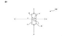
- FIG. 1 is a conceptual diagram for explaining an example of an embodiment of the raw material liquid concentration system of the present invention.
- the raw material liquid concentrating unit 100 has a forward osmosis membrane o and a forward osmosis membrane unit 11 having a raw material liquid side space R and an induction solution side space D separated from each other by the forward osmosis membrane o.
- the forward osmosis membrane unit 11 the raw material solution and the inducing solution are brought into contact with each other through the forward osmosis membrane, and the solvent in the raw material solution is moved to the inducing solution to concentrate the raw material solution and prepare the inducing solution. It is diluted to obtain a concentrated raw material solution and a dilution induction solution.
- the internal space of the forward osmosis membrane unit 11 is divided into two, a raw material liquid side space R and an induction solution side space D, by the forward osmosis membrane o.
- the raw material liquid a which is the object to be concentrated, is introduced into the space R on the raw material liquid side of the forward osmosis membrane unit.
- the induction solution d is introduced into the induction solution side space D of the forward osmosis membrane unit.
- the raw material liquid a contains a solute and a solvent b.
- the inducing solution d preferably contains an inducing substance and further contains a solvent b.
- the osmotic pressure of the inductive solution d is set to be higher than that of the raw material solution a.
- the raw material liquid concentration system of the present embodiment may be a total amount filtration method or a cross-flow filtration method. From the viewpoint of filtration flow rate and suppression of membrane contamination, the cross-flow filtration method is preferable.
- the forward osmosis membrane unit 11 of FIG. 1 shows an example in which the raw material solution a and the induction solution d are directed in a countercurrent manner, but may be in parallel.
- FIG. 2 is a conceptual diagram for explaining another example of the embodiment of the raw material liquid concentration system of the present invention.
- the raw material liquid concentrating system 200 is the same as the raw material liquid concentrating system 100 shown in FIG. 1 except that it further includes a circulation mechanism 21 that reuses the concentrated raw material liquid as the raw material liquid.
- the number of times the raw material liquid a is passed through the circulation mechanism 21 (that is, the number of times the concentrated raw material liquid obtained in the forward osmosis membrane unit is reused as the raw material liquid in the forward osmosis membrane unit) is arbitrary.
- its linear velocity is preferably 0.03 cm / s or more and 15 cm / s or less.
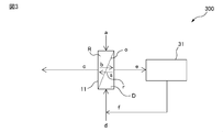
- FIG. 3 is a conceptual diagram for explaining still another example of the embodiment of the raw material liquid concentration system of the present invention.
- the raw material liquid concentrating system 300 is the same as the raw material liquid concentrating system 100 shown in FIG. 1, except that the first inductive solution regeneration unit 31 is further provided.
- the first induction solution regeneration unit is configured to remove the solvent b from the dilution induction solution e and concentrate to obtain the regeneration induction solution f, and to circulate the obtained regeneration induction solution f again as the induction solution d. May be done.
- the removal of the solvent b from the dilution induction solution e by the first induction solution regeneration unit 41 may be performed by a known concentrator, for example, an evaporator or the like.
- the regeneration induction solution f may contain a part of the solvent b.
- the solvent b is a multi-component system containing water and contains an azeotropic component, it is difficult to remove the solvent b. Therefore, the regeneration-inducing solution f contains a part of the solvent b, which is a system problem. It does not become.
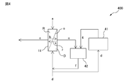
- FIG. 4 is a conceptual diagram for explaining still another example of the embodiment of the raw material liquid concentration system of the present invention.
- the raw material liquid concentrating system 400 is the same as the raw material liquid concentrating system 300 shown in FIG. 3, except that the second inductive solution regeneration unit 41 and the mixing unit 42 are further provided.
- the solvent b is removed from the induction solution d by the second induction solution regeneration unit 41 to obtain the concentration induction solution g, and the obtained concentration induction solution g and the dilution induction solution e are mixed. It may be configured to mix in the unit 42 to produce a mixture (regeneration-inducing solution f) and use the regeneration-inducing solution f as the inducing solution d.
- the removal of the solvent b from the induction solution d by the second induction solution regeneration unit 41 may be performed by a known concentrator, for example, an evaporator or the like.
- the mixing unit 42 may be, for example, a buffer tank or the like.
- the concentrated induction solution g may contain a part of the solvent b.
- the solvent b is a multi-component system containing water and contains an azeotropic component, it is difficult to remove the solvent b. Therefore, the concentration-inducing solution g contains a part of the solvent b, which is a system problem. It does not become.
- FIG. 5 is a conceptual diagram for explaining still another example of the embodiment of the raw material liquid concentration system of the present invention.
- the raw material liquid concentrating system 500 is the same as the raw material liquid concentrating system 400 shown in FIG. 4, except that the circulation mechanism 21 shown in FIG. 2 is further provided.
- FIG. 5 shows an example in which the second induction solution regeneration unit 41 is adopted, but instead of or in addition to this, the first induction solution regeneration unit 31 shown in FIG. 3 is adopted. May be good.
- the raw material liquid a is a fluid containing a solute and a solvent b, and is scheduled to be concentrated by the raw material liquid concentrating system of the present embodiment.
- the raw material liquid a may be an emulsion as long as it is a fluid.
- the raw material liquid is stored in the raw material liquid tank and supplied to the forward osmosis membrane unit via the raw material liquid flow path.
- the raw material liquid a applied to the present embodiment is a pharmaceutical product or a raw material thereof. That is, one aspect of the present invention relates to a raw material liquid concentration system for a pharmaceutical manufacturing process.
- the raw material solution applied to the raw material solution concentration system of the present embodiment which can be used as a raw material for pharmaceuticals, and the concentrated raw material solution obtained from the raw material solution are nucleic acids, oligopeptides, amino acids, antibiotics, small molecule drugs and vitamins, respectively. It is preferable to include at least one selected from the group consisting of.
- the solute contained in the raw material solution preferably contains a compound having a number average molecular weight of 100 to 6000.
- the number average molecular weight of the compound is more preferably 200 to 5000. If the number average molecular weight is 100 or more, it is difficult to permeate the forward osmosis membrane, and if the number average molecular weight is 6000 or less, the raw material components are unlikely to adhere to the surface of the forward osmosis membrane.
- the raw material liquid in the present embodiment preferably contains an oligopeptide because it has a low affinity with the forward osmosis membrane.
- the number average molecular weight is a value measured in terms of standard polyethylene oxide using gel permeation chromatography.
- nucleic acid examples include oligonucleotides, RNA, aptamers, and decoys.
- oligopeptides examples include L-alanyl-L-glutamine, ⁇ -alanyl-L-histidine cyclosporine, and glutathione.
- the "oligopeptide” refers to a compound to which any amino acid having 2 or more residues and less than 50 residues is bound.
- the oligopeptide may be chained or cyclic.
- essential amino acids eg, tryptophan, lysine, methionine, phenylalanine, threonine, valine, leucine, isoleucine, etc.
- non-essential amino acids eg, arginine, glycine
- unnatural amino acid refers to any non-naturally occurring artificial compound having an amino acid skeleton in the same molecule, and can be produced by binding various labeled compounds to the amino acid skeleton.
- amino acid skeleton contains a carboxyl group, an amino group, and a portion connecting these groups in the amino acid.
- Labeled compounds include dye compounds, fluorescent substances, chemical / bioluminescent substances, enzyme substrates, coenzymes, antigenic substances, and protein binding substances known to those skilled in the art.
- labeled amino acid which is an amino acid bound to a labeled compound
- labeled amino acid examples include an amino acid in which a labeled compound is bound to an amino acid having an amino acid skeleton containing an aromatic ring such as a benzene ring in the side chain.
- unnatural amino acids to which a specific function is given include, for example, photoresponsive amino acids, optical switch amino acids, fluorescent probe amino acids, fluorescently labeled amino acids and the like.
- the number average molecular weight of the solute contained in the low molecular weight medicine is 1000 or less, particularly preferably 100 to 1000.
- the low-molecular-weight drug that can be concentrated in the raw material solution concentration system of the present embodiment include various anti-cancer agents, low-molecular-weight drug compounds that serve as substrates for gastrointestinal excretion transporters such as P-gp and BCRP, and sodium risedronate. Examples thereof include therapeutic agents for osteoporosis and Paget's disease of bone, and antiviral agents such as oseltamivir and zanamivir.
- anticancer agents include alkylating agents, antimetabolites, microtubule inhibitors, antibiotic anticancer agents, topoisomerase inhibitors, platinum preparations, hormone agents and the like.
- alkylating agent include cyclophosphamide, ifosfamide, nitrosourea, dacarbazine, temozolomide, nimustine, busulfan, melphalan, procarbazine, and ranimustine.
- Antimetabolites include, for example, enocitabine, carmofur, capecitabine, tegafur, gemcitabine, cytarabine, cytarabine ocphosphat, nerarabine, fluorouracil, fludarabin, pemetrexed, pentostatin, methotrexate, gradribine, doxifluridine, hydroxycarbamide, etc. ..
- the microtubule inhibitor include alkaloid anticancer agents such as vincristine, and taxan anticancer agents such as docetaxel and paclitaxel.
- antibiotic anticancer agents include mitomycin C, doxorubicin, and epirubicin.
- Doxorubicin, bleomycin, actinomycin D, acralubicin, idarubicin, pirarubicin, pepromycin, mitoxanthrone, amrubicin, dinostatin stimalamer and the like can be mentioned.
- the topoisomerase inhibitor include CPT-11 having a topoisomerase I inhibitory action, irinotecan, nogitecan, and etoposide and sobzoxane having a topoisomerase II inhibitory action.
- platinum preparation include cisplatin, nedabratin, oxaliplatin, carboplatin and the like.
- hormonal agents include dexamethasone, finasteride, tamoxifen and the like.
- vitamins that can be concentrated in the raw material liquid concentration system of the present embodiment include vitamin A and its derivatives and their salts, vitamin Bs such as vitamin B6 and vitamin B12, their derivatives, and their salts and vitamin Cs. And their derivatives and their salts.
- the inducing solution d preferably contains an inducing substance and further contains a solvent b.
- the inductive solution d is a fluid that has a higher osmotic pressure than the raw material solution a and does not significantly denature the forward osmotic membrane o.
- the inductive solution is housed in an inductive solution tank and fed to the forward osmosis membrane unit via an inductive solution flow path.
- the induction solution in the present embodiment may be a solution containing one or more selected from salts, sugars, alcohols, polymers and the like.
- the induction solution in the present embodiment preferably contains an inorganic salt as a salt in that it has a high osmotic pressure.
- Examples of the inorganic salt include sodium chloride, potassium chloride, magnesium chloride, calcium chloride, sodium sulfate, magnesium sulfate, sodium thiosulfate, sodium sulfite, ammonium chloride, ammonium sulfate, ammonium carbonate and the like;
- sugars include general sugars such as sucrose, fructose, and glucose, and special sugars such as oligosaccharides and rare sugars;
- Examples of the alcohol include monoalcohols such as methanol, ethanol, 1-propanol and 2-propanol; and glycols such as ethylene glycol and propylene glycol. From the viewpoint of safety, ethanol and 2-propanol are preferable.
- polymer examples include homopolymers and copolymers of monomers such as ethylene oxide and propylene oxide.
- the concentration of the inducing substance in the inducing solution d is set so that the osmotic pressure of the inducing solution d is higher than the osmotic pressure of the raw material liquid a.
- the osmotic pressure of the inductive solution d may fluctuate within the range as long as it is higher than the osmotic pressure of the raw material solution a.
- the method for determining the osmotic pressure difference between the two liquids can be, for example, any of the following methods. (1) When two liquids are mixed and then separated into two phases: After the two phases are separated, it is judged that the osmotic pressure of the liquid with the larger volume is higher, or (2) When the two liquids are mixed and not separated into two phases: The two liquids are brought into contact with each other through the forward osmosis membrane o, and it is judged that the osmotic pressure of the liquid whose volume has increased after a certain period of time is high. The fixed time at this time depends on the osmotic pressure difference, but is generally in the range of several minutes to several hours.
- the solvent b in the raw material liquid a is a liquid.
- the solvent b in the raw material liquid a is preferably one capable of dissolving or dispersing the components in the raw material liquid a, and can be selected from any inorganic solvent or organic solvent.
- the solvent b is often water.
- the solvent b in this embodiment mainly contains water, acetic acid, acetonitrile, methanol, 2-propanol and the like.
- the solvent b in the raw material liquid a is preferably water, acetic acid, acetonitrile, methanol, and / or 2-propanol, or preferably contains water, acetonitrile, methanol, 2-propanol, or a mixture thereof as a main component.
- the main component referred to here means that the solvent b is contained in a proportion of more than 50% by mass, 60% by mass or more, 80% by mass or more, 95% by mass or more, or 100% by mass.
- the solvent that may be contained in the induction solution d is preferably a solvent of the same type as the solvent b that should be separated from the raw material solution a.
- the solvent of the raw material solution a is water
- it is preferable that the solvent of the induction solution d is also water.
- the concentrated raw material liquid c obtained by concentrating the raw material liquid a with the forward osmosis membrane unit was obtained by maintaining the components in the raw material liquid a and selectively separating at least a part of the solvent b. It may be a thing.
- the amount or ratio of the solvent b separated from the raw material liquid a can be arbitrarily controlled.
- the forward osmosis membrane unit of the present embodiment as long as the osmotic pressure of the raw material solution a does not exceed the osmotic pressure of the induction solution d, it is possible to concentrate to near the saturation concentration of the raw material solution a.
- the time for the subsequent treatment (for example, column purification and freeze-drying) can be shortened.
- the time required for freeze-drying and column purification increases significantly as the amount of raw material solution increases. Therefore, it is preferable to concentrate the raw material liquid as a preliminary step of freeze-drying and column purification from the viewpoint of shortening the process time and reducing the energy cost in the pump, heat source, cooling unit and the like.
- Concentration with the forward osmosis membrane unit, freeze-drying, and column purification may be continuously performed without any time interval, or may be performed at predetermined time intervals.
- the concentrated raw material solution obtained by concentration may be temporarily stored, and freeze-dried and column-purified after a lapse of a predetermined time.
- the forward osmosis membrane unit it is possible to obtain a high concentration ratio while maintaining a high level of raw material liquid components. Further, since an arbitrary concentration ratio can be obtained by changing the inducer, the types of raw material liquids to which the raw material liquid concentration system of the present embodiment can be applied are various, and substantially any liquid can be concentrated. Is. Therefore, according to this embodiment, high quality concentrates can be obtained with high efficiency even when it is impossible or difficult to apply the prior art.
- the present embodiment relates to a raw material liquid concentration system for a pharmaceutical manufacturing process.
- the raw material liquid concentration system of the present embodiment when applied to the concentration of a drug or a raw material thereof, it is possible to concentrate the drug while maintaining its medicinal efficacy.
- the forward osmosis membrane unit 11 has a forward osmosis membrane o and an internal space divided into two, a raw material liquid side space R and an induction solution side space D, by the forward osmosis membrane o.
- the forward osmosis membrane o is a membrane having a function of allowing the solvent b to permeate but not allowing the solute to permeate or making it difficult to permeate.
- the forward osmosis membrane o may have a function of back-diffusing the inducing substance s in the inducing solution d into the concentrated raw material solution c.
- the forward osmosis membrane o may be a membrane that also has a function as a reverse osmosis membrane.
- the reverse osmosis process in which the solvent is removed by pressure and the forward osmosis process in which the difference in osmotic pressure between the raw material solution and the inductive solution is utilized are appropriate due to the difference in the driving force utilized for solvent removal.
- the membrane structure is different. In a system used for a forward osmosis process, such as the raw material liquid concentration system of the present embodiment, it is preferable to use a membrane having a higher function as a forward osmosis membrane.
- the shape of the forward osmosis membrane o examples include a hollow fiber membrane, a flat membrane, a spiral membrane, and the like.
- the forward osmosis membrane is a hollow fiber membrane.
- the forward osmosis membrane o is preferably a composite type membrane having a separation active layer on the support layer (support membrane).
- the support membrane may be a flat membrane or a hollow fiber membrane.
- the separation active layer may be present on one side or both sides of the support membrane.
- the separation active layer may be present on the outer surface or inner surface of the hollow fiber membrane, or both surfaces.
- the support membrane in the present embodiment is a membrane for supporting the separation active layer, and it is preferable that the support membrane itself does not substantially exhibit separation performance with respect to the separation target.
- the support film any film including known microporous support film, non-woven fabric and the like can be used.
- the preferred support membrane in the present embodiment is a microporous support membrane, particularly a microporous hollow fiber support membrane.
- the fine pore hollow fiber support membrane has fine pores having a pore diameter of preferably 0.001 ⁇ m or more and 0.1 ⁇ m or less, more preferably 0.005 ⁇ m or more and 0.05 ⁇ m or less on the inner surface thereof.
- the structure from the inner surface of the microporous hollow fiber support membrane to the outer surface in the depth direction of the membrane in order to reduce the permeation resistance of the permeating fluid, the structure is as sparse as possible while maintaining the strength. It is preferable to have.
- the sparse structure of this portion is preferably, for example, a net-like, finger-like void, or a mixed structure thereof.
- the flat or hollow filamentous normal osmotic film o includes polyethersulfone, polysulfone, polyketone, polyetheretherketone, polyphenylene ether, polyvinylidene fluoride, polyacrylonitrile, polyimine, and polyimide from the viewpoint of the inhibition rate of the inducer.
- a film having a thin film layer containing at least one selected from the group consisting of polybenzoxazole, polybenzoimidazole, sulfonated tetrafluoroethylene, and polyamide as a main component is preferable.
- Polyamide can be formed by interfacial polymerization of polyfunctional acid halide and polyfunctional aromatic amine.
- a preferred example of a polyfunctional acid halide is a polyfunctional aromatic acid halide.
- the polyfunctional aromatic acid halide is an aromatic acid halide compound having two or more acid halide groups in one molecule. Specifically, for example, trimesic acid halide, trimellitic acid halide, isophthalic acid halide, terephthalic acid halide, pyromellitic acid halide, benzophenone tetracarboxylic acid halide, biphenyldicarboxylic acid halide, naphthalenedicarboxylic acid halide, pyridinedicarboxylic acid halide, etc.
- Examples thereof include benzenedisulfonic acid halides, which can be used alone or in admixture thereof.
- the halide ion in these aromatic acid halide compounds include chloride ion, bromide ion, and iodide ion.
- particularly trimesic acid chloride alone, a mixture of trimesic acid chloride and isophthalic acid chloride, or a mixture of trimesic acid chloride and terephthalic acid chloride is preferably used.
- the polyfunctional aromatic amine is an aromatic amino compound having two or more amino groups in one molecule.
- Interfacial polymerization of polyfunctional acid halides and polyfunctional aromatic amines can be carried out according to a conventional method.
- a perfluorosulfonic acid polymer generally refers to a polymer having a side chain having a sulfonic acid in a main chain skeleton in which a part or all of hydrogen is replaced with fluorine.
- Perfluorosulfonic acid polymers are used, for example, as chemically stable cation exchange resins or ion-selective permeable membranes, for example, in salt electrolysis, polymer electrolyte fuel cells, water electrolysis, or various sensors.
- the chemical structure of the perfluorosulfonic acid polymer is not particularly limited, but is typically represented by the following formula (1);
- Y is-(CF 2- CF (CF 3 ) -O-) m- (CF 2 ) n- SO 3 H, x is 0.06 to 0.5, and m is 0 to.
- the structure is an integer of 2 and n is an integer of 1-6 ⁇ .
- “(CF 2 -CF 2)" units and “(CF 2 -CF (OY))” sequence of units has been described for convenience in succession may be a block, a random It may be good, or it may be a combination thereof.
- a hollow fiber-like forward osmosis membrane it is preferable to use a hollow fiber-like forward osmosis membrane, and it is particularly preferable to use a composite hollow fiber having a separation active layer made of a polymer thin film on the inner surface of the hollow fiber-like porous support membrane.
- the outer diameter of the hollow fiber membrane is, for example, 300 ⁇ m or more and 5,000 ⁇ m or less, preferably 350 ⁇ m or more and 4,000 ⁇ m or less
- the inner diameter of the hollow fiber membrane is, for example, 200 ⁇ m or more and 4 It is 000 ⁇ m or less, preferably 500 ⁇ m or more and 1,500 ⁇ m or less.
- a plurality of hollow fiber membranes may form a hollow fiber bundle.
- a plurality of hollow fiber membrane yarn bundles may preferably be housed in a suitable housing to form a membrane module.
- the hollow fiber membrane constituting the hollow fiber bundle comprises a microporous support membrane and a separation active layer which is a polymer polymer thin film provided on the inner surface of the microporous support membrane.
- the membrane area of the hollow fiber yarn bundle is preferably 0.01 m 2 or more, more preferably 1 m 2 or more.
- the membrane area of the hollow fiber yarn bundle may be, for example, 20 m 2 or less, or 10 m 2 or less, from the viewpoint of ease of manufacturing the membrane module.
- the permeation flux of the forward osmosis membrane o with respect to the solvent b is 0.1 L / (m 2 ⁇ hr) or more and 50 L / (m 2 ⁇ hr) as the initial permeation flux of the forward osmosis membrane (that is, at the start of operation).
- the following is preferable.
- the initial permeation flux is 0.1 L / (m 2 ⁇ hr) or more, the separation efficiency of the solvent b is not easily impaired, and if it is 50 L / (m 2 ⁇ hr) or less. , It is easy to prevent the solute contained in the raw material liquid from sticking to the film surface.
- the permeated flux for the solvent b in the present disclosure means the amount of the solvent b passing through the forward osmosis membrane o, which is allocated per unit area of the forward osmosis membrane o and per unit time. It is defined by the formula (1).
- F L / (M ⁇ H) (1)
- F is the permeated flux (L / (m 2 ⁇ hr)) for the solvent b
- L is the amount (L) of the permeated solvent b
- M is the surface area (m 2 ) of the forward osmosis membrane o.
- H is the time (hr).
- the permeated flux when the solvent b is water is generally referred to as the "permeability".
- the permeation flux of the solute contained in the induction solution in the present disclosure means the amount of the dissolved mass in the induction solution passing through the forward osmosis membrane o allocated per unit area of the forward osmosis membrane o and per unit time. It is defined by the following formula (2).
- F' L'/ (M ⁇ H) (2)
- F' is the permeated flux [g / (m 2 x hr)] for the solute in the inductive solution
- L' is the amount of permeated solute (g)
- M is the surface area of the forward osmotic membrane (m 2 ).
- H is the time (hr).
- the ratio of the permeated flux that moves the solute in the inducing solution into the raw material liquid and the permeated flux of the solvent that moves from the raw material liquid into the inducing solution (permeated flux of the inducing substance / permeation of the solvent). (Flux) is defined by the following formula (3).
- R F'/ F (3)
- R is the ratio [g / L] of the permeated flux that moves the solute in the inductive solution into the raw material liquid and the permeated flux of the solvent that moves from the raw material liquid into the inductive solution.
- the ratio of the permeated flux that moves the solute in the inducing solution into the raw material solution to the permeated flux of the solvent b that moves from the raw material solution into the inducing solution is 3 g / L or less.
- the above ratio is 3 g / L or less, the dissolved mass in the inductive solution that moves into the raw material solution is relatively small, so that the purity of the raw material solution can be ensured.
- the above ratio is 0.001 g / L or more, the yield of the raw material liquid is high, which is preferable.
- the coefficient of variation of the thickness of the separation active layer in the radial direction and the length direction of the hollow yarn bundle is 0 to 60%. ..
- the membrane area of the hollow fiber membrane bundle is within the range exemplified above, and the coefficient of variation of the thickness of the separation active layer of the hollow fiber yarn bundle is within the above range.
- the coefficient of variation is a value obtained by dividing the standard deviation of the thickness value of the separation active layer at each measurement point by the average value, and is expressed as a percentage (%).
- the thickness at each measurement point is expressed as the average thickness in the measurement range of about 5 to 100 ⁇ m in length.
- the length of this measuring range is preferably 5 to 50 ⁇ m, more preferably 5 to 20 ⁇ m, and most preferably 13 ⁇ m.
- the separation active layer of the present embodiment preferably has a fine uneven shape on its surface, as will be described later. Therefore, when evaluating the thickness of the separation active layer, it is appropriate to evaluate by the average thickness of the measurement range at each measurement point.
- the separation active layer of the present embodiment has a small variation when the average thickness measured at a plurality of measurement points is compared.
- the length direction of the measurement range in the evaluation of the average thickness may be the length direction of the hollow fiber, the circumferential direction of the hollow fiber, or the length direction of the hollow fiber. It may be in an oblique direction.
- the directions of the lengths of the measurement ranges in the plurality of scanning electron microscope images used for calculating the average value may be the same direction or different directions from each other.
- Each of the above is preferably 0 to 60%, more preferably 0 to 50%, still more preferably 0 to 40%, and most preferably 0 to 30%.
- the present inventors infer the mechanism by which the surface of the separation active layer of the present embodiment has such a fine concave shape as follows.
- the present invention is not bound by the following theory.
- the separation active layer of the present embodiment is preferably formed by interfacial polymerization.
- interfacial polymerization when the liquid film of the first monomer solution formed on the surface of the hollow yarn comes into contact with the second monomer solution, it is considered that the two do not incompatible and the polymerization proceeds at the interface to form a polymerized layer. Be done. As a result, it is considered that the formed separation active layer has a shape with many fine irregularities on the surface. If the separation active layer is formed by a method other than interfacial polymerization, the separation active layer having a shape with many surface fine irregularities is not formed.
- the raw material liquid concentrating system is configured to apply a pressure of 10 kPa or more and 200 kPa or less from the inside to the outside of the hollow fiber membrane as a forward osmosis membrane. According to such a configuration, the raw material liquid can be concentrated with high efficiency.
- the above pressure can be realized by injecting a predetermined flow rate at a set pressure, for example, by installing a back pressure valve on the discharge pipe of the pump.
- TESCOM 44-2362-24-595
- the pressure can be measured by a pressure measuring device, for example, manufactured by KEYENCE (GP-M010).
- the raw material liquid concentration system 100 has a raw material liquid flow path, an induction solution flow path, a concentration liquid flow path, and a dilution induction solution flow path.
- the raw material liquid a which is the object to be concentrated, is introduced into the raw material liquid side space R of the forward osmosis membrane unit 11 from the raw material liquid flow path, and the induction solution d is introduced into the induction solution side space D from the induction solution flow path.
- the directions of these flows may be countercurrent or parallel to each other.
- the concentrated raw material liquid may be taken out through the concentrated liquid flow path, and the dilution inducing solution may be taken out through the dilution inducing solution flow path.
- the dilution induction solution may be regenerated in the induction solution regeneration unit below.
- the linear velocity of the raw material liquid a introduced into the raw material liquid side space R of the forward osmosis membrane unit is preferably 0.03 cm / s or more and 15 cm / s or less. Although the reason is not clear, if it is 0.03 cm / s or more, the time for the raw material liquid to come into contact with the film does not become too long, and the solute contained in the raw material liquid is unlikely to adhere to the film surface. If it is 15 cm / s or less, the pressure pressed against the film does not become too large, and the solute contained in the raw material solution is unlikely to adhere to the film surface.
- the temperature of the raw material liquid a introduced into the raw material liquid side space R of the forward osmosis membrane unit is preferably 3 ° C. or higher and 60 ° C. or lower, and more preferably 5 ° C. or higher and 50 ° C. or lower. Although the reason is not clear, when the temperature of the raw material liquid a is 3 ° C. or higher, the permeation flux is unlikely to slow down, and when the temperature is 60 ° C. or lower, the components in the raw material liquid a are difficult to denature.
- the temperature of the inductive solution d introduced into the inductive solution side space D of the forward osmosis membrane unit is preferably 5 ° C. or higher and 60 ° C. or lower, and more preferably 10 ° C. or higher and 50 ° C. or lower. Although the reason is not clear, when the temperature of the inducing solution d is 5 ° C. or higher or 60 ° C. or lower, the amount of the inducing substance transferred from the inducing solution d to the raw material liquid a via the forward osmosis membrane o is less likely to increase, which is preferable. ..
- the raw material liquid concentration system may include a raw material liquid temperature adjusting mechanism and / or an induced solution temperature adjusting mechanism. According to these temperature adjusting mechanisms, the temperature of the raw material solution and / or the induction solution can be easily controlled within the above range, for example.
- the temperature control mechanism exhaust heat from a heat exchanger or an industrial process can be used. It is preferable to use exhaust heat as a heat source because the amount of energy newly consumed for separating the solvent b can be reduced.
- the raw material liquid concentration system of the present embodiment may further include an induction solution regeneration unit.
- the inductive solution regeneration unit may be, for example, as follows. (1) A unit in which the solvent b is removed from the dilution induction solution e to obtain a regeneration induction solution f which is a concentrate of the dilution induction solution e, and the obtained regeneration induction solution f is supplied as the induction solution d (for example, FIG. The solvent b was removed from the first induction solution regeneration unit 31) and / or (2) induction solution d shown in 3, to obtain a concentration induction solution g which is a concentrate of the induction solution d, and the obtained concentration was obtained. A unit (for example, the second induction solution shown in FIG. 4) in which the induction solution g and the dilution induction solution e are mixed to obtain a mixture (regeneration induction solution f) and the obtained regeneration induction solution f is supplied as the induction solution d. Reproduction unit 41).
- the first and second induction solution regeneration units may be, for example, an evaporator.
- the evaporator may include, for example, a distiller, a forward osmosis membrane, a membrane distillation unit, and the like.
- the diluter adjusts the dilution induction solution e or the induction solution d to a predetermined temperature, and then feeds the solution into the distillation column to obtain the solvent b from the top of the column, and the solvent b is removed from the bottom of the column to concentrate the solution b. It may be configured to obtain a concentration-inducing solution g, which is a concentration-inducing solution in which the regeneration-inducing solution f, which is a dilution-inducing solution, or the solvent b is removed.
- the dilution induction solution e or the induction solution d is circulated so as to be in contact with the forward osmosis membrane, and the solvent b contained in the dilution induction solution e or the induction solution d is removed through the forward osmosis membrane.
- the solvent b and the regeneration-inducing solution f or the concentration-inducing solution g can be produced.
- the membrane distillation unit may be a membrane unit having a separation chamber divided into a liquid phase portion and a gas phase portion by a semipermeable membrane.
- a membrane distillation unit using a forward osmosis membrane or a semipermeable membrane is preferable because the equipment size is small, and the transfer of the inducer from the dilution induction solution e or the induction solution d to the solvent b is performed.
- a membrane distillation unit using a semipermeable membrane is more preferable in that it can be suppressed. The elements used in the membrane distillation unit will be described below.
- Examples of the shape of the semipermeable membrane used in the membrane distillation unit include a hollow fiber membrane shape, a flat membrane shape, and a spiral membrane shape.
- the flat membrane-like semipermeable membrane may be composed of, for example, a single layer, or may have a support layer and a separation active layer on the support layer.
- the hollow thread-like semipermeable membrane may be, for example, a hollow thread composed of a single layer, a hollow thread-like support layer, an outer surface or an inner surface of the support layer, or both surfaces thereof. It may have the above separation active layer.
- the material of the support layer and the separation active layer in the semipermeable membrane may be any material selected from the materials exemplified above for the forward osmosis membrane o, respectively.
- the permeation flux of the semipermeable membrane with respect to the solvent b is preferably 1 L / (m 2 ⁇ hr) or more and 200 L / (m 2 ⁇ hr) or less. If the permeation flux is 1 L / (m 2 x hr) or more, the efficient separation of the solvent b is not easily impaired, and if it is 200 L / (m 2 x hr) or less, the semipermeable membrane from the induction solution d. The amount of the inducer that passes through the solvent b and moves to the solvent b is unlikely to increase.
- This permeation flux is defined in the same way as the permeation flux for the solvent b of the forward osmosis membrane o.
- the temperature of the dilution induction solution e or the induction solution d is adjusted in the range of 20 ° C. or higher and 90 ° C. or lower before being introduced into the liquid phase portion of the membrane distillation unit.
- this temperature is 20 ° C. or higher, the efficiency of separation of the solvent b by membrane distillation is not easily impaired, and when it is 90 ° C. or lower, the inducing substance contained in the dilution inducing solution e or the inducing solution flow d is a semipermeable membrane. The amount of transfer to the solvent b through the above is unlikely to increase.
- a heat source for heating the dilution induction solution e or the induction solution d for example, exhaust heat from a heat exchanger or an industrial process can be used. It is preferable to use exhaust heat as a heat source because the amount of energy newly consumed for separating the solvent b can be reduced.
- the gas phase portion of the membrane distillation unit is preferably depressurized to a predetermined pressure.
- the pressure of the gas phase portion may be appropriately set according to the scale of the apparatus, the concentration of the induction solution d, the production rate of the desired solvent b, etc., but is preferably 0.1 kPa or more and 80 kPa or less, for example. More preferably, it is 1 kPa or more and 50 kPa or less.
- Examples of the decompression device for depressurizing the gas phase portion of the membrane distillation unit include a diaphragm vacuum pump, a dry pump, an oil rotary vacuum pump, an ejector, and an aspirator.
- the solvent b is separated from the dilution induction solution e to become a enriched dilution induction solution f, which is discharged from the membrane distillation unit.
- the obtained regeneration-inducing solution f can be reused as the inducing solution d after being mixed with the dilution-inducing solution e as necessary and adjusted to a predetermined concentration.
- the temperature of the regeneration-inducing solution f may be adjusted by using a cooling device.
- the solvent b is separated from the induction solution d to become a concentrated induction solution g, which is a concentrated induction solution, and is discharged from the membrane distillation unit.
- the obtained concentration-inducing solution g is mixed with the dilution-inducing solution e and adjusted to a predetermined concentration to become a regeneration-inducing solution f.
- the regeneration-inducing solution f can be reused as the induction solution d as it is, or the mixture of the regeneration-inducing solution f mixed with the induction solution can be reused as the induction solution d.
- the temperature of the concentration-inducing solution g may be adjusted by using a cooling device.
- the cooling device for example, a chiller, a heat exchanger, or the like can be used.
- the solvent b separated from the induction solution d by these induction solution regeneration units may be reused as needed.
- ⁇ Recovery rate of solute> According to the raw material liquid concentration system of the present embodiment as described above, a high-concentration concentrate can be obtained with high efficiency while maintaining the composition of the components (specifically, the solute) contained in the raw material liquid. The higher the degree of maintenance of the component composition by concentration, the higher the recovery rate of the raw material solution obtained after concentration.
- the analysis of the component composition in the obtained concentrate may be appropriately selected according to the type of the raw material liquid and the components contained in the concentrate. For example, gravimetric method, ICP-MS (inductively coupled high frequency plasma mass spectrometry), nuclear magnetic resonance spectroscopy (NMR) method, gas chromatography mass spectrometry (GC / MS) method, colorimetric method, fluorescence method, high performance liquid chromatograph ( Various known analytical methods such as HPLC) can be used.
- ICP-MS inductively coupled high frequency plasma mass spectrometry
- NMR nuclear magnetic resonance spectroscopy
- GC / MS gas chromatography mass spectrometry
- colorimetric method fluorescence method
- high performance liquid chromatograph Various known analytical methods such as HPLC
- the recovery rate of the solute by the forward osmosis membrane unit is preferably 70% or more and 99.9% or less. More preferably, it is 90% or more and 99.9% or less, and further preferably 95% or more and 99.9% or less. Since the raw material is expensive, if the recovery rate is 70% or more, the increase in cost can be suppressed. Moreover, it is practically difficult to obtain a recovery rate exceeding 99.9%.
- Raw material liquid concentration method One aspect of the present invention is A raw material solution containing a solvent and a solute and an inducing solution containing an inducing substance are brought into contact with each other via a forward osmosis membrane, the solvent in the raw material solution is moved into the inducing solution, and induction in the inducing solution is performed.
- a method for concentrating a raw material solution for a pharmaceutical production process which comprises a first step of obtaining a concentrated raw material solution and a dilution induction solution by moving a substance into the raw material solution.
- the method may be carried out using the raw material solution concentration system described above. Therefore, the components such as the forward osmosis membrane (hollow fiber membrane, etc.), the membrane module, the raw material liquid, and the inductive solution used in the method may be the same as those illustrated in the section ⁇ Raw material liquid concentration system >>.
- the components such as the forward osmosis membrane (hollow fiber membrane, etc.), the membrane module, the raw material liquid, and the inductive solution used in the method may be the same as those illustrated in the section ⁇ Raw material liquid concentration system >>.
- the first step as illustrated in the section ⁇ Raw material liquid concentration system >>, -Supplying the raw material solution and the inductive solution from the inside to the outside of the hollow fiber as a forward osmosis membrane so that a pressure of 10 kPa or more and 200 kPa or less is applied. -Adjust the temperature of the raw material solution to the range of 5 ° C or higher and 50 ° C or lower.
- the circulation linear velocity for circulating the concentrated raw material solution should be 0.03 cm / s or more and 15 cm / s or less, and-The initial permeation flux of the forward osmosis membrane should be 0.1 L / (m 2 x hr) or more and 50 L / ( m 2 x hr) or less, One or two or more of them may be performed.
- the raw material solution concentration method may further include a first induction solution regeneration step in which the solvent is removed from the dilution induction solution to obtain a regeneration induction solution, and the obtained regeneration induction solution is used again as the induction solution.
- the first induction solution regeneration step may be carried out using the first induction solution regeneration unit exemplified in the section ⁇ Raw Material Solution Concentration System >>.
- removal of the solvent from the dilution induction solution in the first induction solution regeneration step is performed by evaporation means.
- the evaporation means may be an evaporator as exemplified in the section ⁇ Raw Material Solution Concentration System >>.
- the raw material solution concentration method further involves a second induction solution regeneration step in which the solvent is removed from the induction solution to obtain a concentration induction solution, and the mixture of the obtained concentration induction solution and the dilution induction solution is used as the induction solution. May have.
- the second induction solution regeneration step may be carried out using the second induction solution regeneration unit exemplified in the section ⁇ Raw material solution concentration system >>.
- the removal of the solvent from the induction solution in the second induction solution regeneration step is performed by the evaporation means.
- the evaporation means may be an evaporator as exemplified in the section ⁇ Raw Material Solution Concentration System >>.
- Permeated flux of inducer (g / m 2 / hr)
- the permeation flux of the inducing substance which moves the inducing substance in the inducing solution into the raw material solution, was measured by the following method. After the operation was completed, the amount of solute contained in the inductive solution contained in the concentrated raw material solution was measured using ICP-MS manufactured by Thermo Fisher Scientific Co., Ltd., in the form of "iCAP Q". From the above-mentioned mathematical formula (3), the permeation flux of the solute moved by the operation was calculated.
- Circulation velocity (cm / s)
- the linear velocity of the concentrated raw material solution in the circulation mechanism was calculated by the following formula.
- X Y / Z
- X is the linear velocity of the concentrated raw material liquid [cm / s]
- Y is the flow velocity of the concentrated raw material liquid [cm 3 / s]
- Z is the total hollow fiber inner cross-sectional area [cm 2 ].
- the flow velocity of the concentrated raw material liquid was measured using the format "FD-X" manufactured by KEYENCE CORPORATION.
- Example 1 The following examples were carried out using the raw material liquid concentration system 500 having the configuration shown in FIG. ⁇ Preparation of raw material liquid concentration system ⁇ ⁇ Preparation of forward osmosis membrane unit 11 having forward osmosis membrane o> (1) Preparation of Hollow Fiber Support Membrane Module 20% by mass of polyether sulfone (PES: manufactured by BASF, trade name "Ultrason”) dissolved in N-methyl-2-pyrrolidone (manufactured by Wako Pure Chemical Industries, Ltd.). Hollow fiber spinning stock solution was prepared. A wet hollow fiber spinning machine equipped with a double spinner was filled with the above stock solution and extruded into a coagulation tank filled with water to form hollow fibers by phase separation.
- PES polyether sulfone
- N-methyl-2-pyrrolidone manufactured by Wako Pure Chemical Industries, Ltd.
- the obtained hollow fiber was wound on a winder.
- the outer diameter of the obtained hollow fiber was 1.0 mm, the inner diameter was 0.7 mm, and the diameter of the fine pores on the inner surface was 0.05 ⁇ m.
- This hollow fiber was used as a support film.
- the 130 hollow fiber support membranes were filled in a cylindrical plastic housing having a diameter of 2 cm and a length of 10 cm, and both ends were fixed with an adhesive to prepare a membrane module having an effective inner surface area of 0.023 m 2 .
- trimesic acid chloride 0.8 g was placed in another 0.5 L container, and 399.2 g of n-hexane was added and dissolved to prepare 0.4 kg of a second solution used for interfacial polymerization.
- the core side of the membrane module (inside the hollow fiber) was filled with the first solution, allowed to stand for 30 minutes, and then the liquid was drained to form a thin liquid film of the first solution inside the hollow fiber.
- the core side pressure was set to normal pressure by the core side pressure adjusting device, and the shell side pressure was set to a reduced pressure of 10 kPa as an absolute pressure by the shell side pressure adjusting device.
- the second solution was pumped to the core side at a flow rate of 1.5 L / min for 3 minutes to perform interfacial polymerization. ..
- the polymerization temperature was 25 ° C.
- the membrane module was removed from the apparatus, and nitrogen at 50 ° C. was flowed to the core side for 30 minutes to fly n-hexane.
- a forward osmosis membrane unit 11 which is a module of a hollow fiber-shaped forward osmosis membrane o having a separation active layer made of polyamide on the inner surface of the hollow fiber support membrane was prepared.
- the obtained pellets were melt-kneaded at 240 ° C. with a twin-screw kneading extruder and extruded into hollow filaments to obtain hollow fibers.
- a hollow fiber forming spun is attached to the extrusion port in the head at the tip of the extruder, and the kneaded melt is extruded from the ring hole for extrusion of the melt, and at the same time, inside the ring hole for extrusion of the melt.
- extrusion was performed in the form of a hollow fiber.
- the hollow filament was introduced into a water bath (40 ° C.) at a free running distance of 20 cm and wound at a speed of 20 m / min.
- the obtained hollow filaments were continuously picked up by a pair of first endless track type belt pickers at a speed of 20 m / min, and a first heating tank (0.8 m length) controlled to a space temperature of 40 ° C. was used. After passing through, the belt was picked up by a second track type belt picker at a speed of 40 m / min and stretched 2.0 times in the length direction. Next, after passing through a second heating tank (0.8 m length) controlled to a space temperature of 80 ° C., the mixture is cooled while being periodically bent on the water surface of a cooling water tank at 20 ° C., and then a third endless track.
- the hollow filament after the above treatment was immersed in methylene chloride to extract and remove DOP and DBP, and then dried.
- the hollow filament was immersed in a 50 mass% ethyl alcohol aqueous solution and then immersed in a 5 mass% sodium hydroxide aqueous solution at 40 ° C. for 1 hour to extract and remove silica. Then, it was washed with water and dried to obtain a hollow fiber membrane.
- the outer diameter of the obtained hollow fiber was 1.25 mm, the inner diameter was 0.70 mm, and the diameter of the fine pores on the inner surface was 0.1 ⁇ m. This hollow fiber was used as a porous membrane.
- a membrane distillation unit which is a membrane module, was prepared.
- the permeation flux (permeability) of water in this membrane distillation unit measured using pure water as the treatment solution and 3.5 mass% saline as the induction solution was 20.02 L / (m 2 x hr). Met.
- Example 1 the L-alanyl-L-glutamine aqueous solution was concentrated.
- the circulation mechanism 21 was used as needed.
- the above-mentioned L-alanyl-L-glutamine aqueous solution was concentrated using the raw material liquid concentration system 500 having the configuration shown in FIG.
- the raw material solution a (L-alanyl-L-glutamine aqueous solution) was applied at a linear velocity of 3.3 cm / s, and the induction solution d was applied at a linear velocity of 1.9 cm. At / s, each flowed. At this time, the temperature of the raw material liquid a was maintained at 25 ° C., and filtration was performed by a cross-flow method.
- the inducing solution d an aqueous solution containing 20% by mass of magnesium chloride was used as the inducing substance. 1 L of the raw material liquid a was concentrated to 100 cm 3 while being circulated using the circulation mechanism 21 as needed. If the concentration could be concentrated to a predetermined concentration by passing the forward osmosis membrane unit only once, the circulation mechanism was not used.
- Induction Solution Regeneration Step An induction solution regeneration step was performed using the membrane distillation unit prepared above to keep the concentration of the inducing substance in the inducing solution constant.
- the induction solution d is flowed through the above-mentioned membrane distillation unit at a flow rate of 600 ml / min, adjusted by a vacuum pump so that the pressure of the gas phase portion of the membrane distillation unit becomes 10 kPa in absolute pressure, and membrane distillation is performed to concentrate.
- Induction solution g was obtained.
- the dilution induction solution e obtained in the first step and the concentration induction solution g obtained by membrane distillation are mixed in a buffer tank to prepare (regenerate) the induction solution d, which is circulated in the first step. used.
- Measuring device "ECS-400" (400MHz) manufactured by JEOL Ltd.
- Sample amount 10 ⁇ L
- Deuterated solvent DEUTERIUM OXIDE (manufactured by Tokyo Chemical Industry Co., Ltd.) 700 ⁇ L
- Internal standard substance: DSS-d6 manufactured by Fuji Film Wako Pure Chemical Industries, Ltd.
- 0.007 mol / L In the obtained 1 H-NMR spectrum, when the peak area of the methyl group of 0 ppm DSS-d6 was set to 100, the peak area values between 0.2 and 4 ppm and between 6 and 10 ppm were obtained, and after concentration.
- the recovery rate of the raw material liquid a after concentration was calculated from the peak area value / peak area value before concentration ⁇ 100, and evaluated according to the following criteria. When an organic solvent was contained, the area value was calculated excluding the corresponding NMR peak. The results are shown in Table 1.
- D When the recovery rate is less than 70%.
- the purity of the raw material solution after concentration is calculated from the true amount of raw material after concentration x 100. It was evaluated according to the following criteria. The results are shown in Table 1.
- the sample was prepared by freezing and splitting as follows.
- the hollow fiber is immersed in ethanol (manufactured by Wako Pure Chemical Industries, Ltd.), and gelatin capsule No. After encapsulation in 00 (manufactured by Wako Pure Chemical Industries, Ltd.), it was immersed in liquefied nitrogen for 5 minutes and frozen.
- the hollow fibers were cut together with the frozen capsules using a chisel and a mallet. Then, the obtained cut product was freeze-dried to obtain a hollow fiber cross-section sample for observation with a scanning electron microscope.
- Example 2 As the inducing solution d, an aqueous solution containing 10% by mass of magnesium chloride was used as the inducing substance. Other than this, the evaluation was carried out under the same conditions as in Example 1. The results are shown in Table 1.
- Example 3 The evaluation was carried out under the same conditions as in Example 2 except that a pressure of 100 kPa was applied from the inside to the outside of the hollow fiber. The results are shown in Table 1.
- Example 4 The evaluation was carried out under the same conditions as in Example 2 except that the solvent b was water. The results are shown in Table 1.
- Example 5 The evaluation was carried out under the same conditions as in Example 3 except that the solvent b was water. The results are shown in Table 1.
- Example 6 The evaluation was carried out under the same conditions as in Example 2 except that a pressure of 10 kPa was applied from the inside to the outside of the hollow fiber. The results are shown in Table 1.
- Example 7 The evaluation was carried out under the same conditions as in Example 2 except that a pressure of 200 kPa was applied from the inside to the outside of the hollow fiber. The results are shown in Table 1.
- Example 8 The evaluation was carried out under the same conditions as in Example 1 except that the interfacial polymerization was carried out as follows. 10 g of m-phenylenediamine and 0.8 g of sodium lauryl sulfate were placed in a 0.5 L container, and 489.2 g of pure water was further added and dissolved to prepare 0.5 kg of a first solution used for interfacial polymerization.
- trimesic acid chloride 0.8 g was placed in another 0.5 L container, and 399.2 g of n-hexane was added and dissolved to prepare 0.4 kg of a second solution used for interfacial polymerization.
- the core side (inside of the hollow fiber) of the microporous hollow fiber membrane module was filled with the first solution, allowed to stand for 30 minutes, and then drained to form a thin liquid film of the first solution inside the hollow fiber. ..
- the core side pressure was set to normal pressure by the core side pressure adjusting device, and the shell side pressure was set to a reduced pressure of 10 kPa as an absolute pressure by the shell side pressure adjusting device.
- the second solution was pumped to the core side at a flow rate of 1.5 L / min for 3 minutes to perform interfacial polymerization. ..
- the polymerization temperature was 25 ° C.
- the hollow fiber membrane module was removed from the apparatus, and nitrogen at 50 ° C. was flowed to the core side for 30 minutes to fly n-hexane. Further, a hollow fiber support membrane module was produced by washing both the shell side and the core side with pure water.
- a forward osmosis membrane unit 11 which is a module of a hollow fiber-shaped forward osmosis membrane o having a separation active layer made of polyamide on the inner surface of the hollow fiber support membrane. ..
- Table 1 The results are shown in Table 1.
- Example 9 The evaluation was carried out under the same conditions as in Example 1 except that the interfacial polymerization was carried out as follows.
- trimesic acid chloride 0.8 g was placed in another 0.5 L container, and 399.2 g of n-hexane was added and dissolved to prepare 0.4 kg of a second solution used for interfacial polymerization.
- the core side (inside of the hollow fiber) of the microporous hollow fiber membrane module was filled with the first solution, allowed to stand for 30 minutes, and then drained to form a thin liquid film of the first solution inside the hollow fiber. ..
- the core side pressure was set to normal pressure by the core side pressure adjusting device, and the shell side pressure was set to a reduced pressure of 10 kPa as an absolute pressure by the shell side pressure adjusting device.
- the second solution was pumped to the core side at a flow rate of 1.5 L / min for 3 minutes to perform interfacial polymerization. ..
- the polymerization temperature was 25 ° C.
- the hollow fiber membrane module was removed from the apparatus, and nitrogen at 50 ° C. was flowed to the core side for 30 minutes to fly n-hexane. Further, a hollow fiber support membrane module was produced by washing both the shell side and the core side with pure water.
- a forward osmosis membrane unit 11 which is a module of a hollow fiber-shaped forward osmosis membrane o having a separation active layer made of polyamide on the inner surface of the hollow fiber support membrane. ..
- Table 1 The results are shown in Table 1.
- Example 10 The evaluation was carried out under the same conditions as in Example 1 except that the interfacial polymerization was carried out as follows.
- trimesic acid chloride 0.8 g was placed in another 0.5 L container, and 399.2 g of n-hexane was added and dissolved to prepare 0.4 kg of a second solution used for interfacial polymerization.
- the core side (inside of the hollow fiber) of the microporous hollow fiber membrane module was filled with the first solution, allowed to stand for 30 minutes, and then drained to form a thin liquid film of the first solution inside the hollow fiber. ..
- the core side pressure was set to normal pressure by the core side pressure adjusting device, and the shell side pressure was set to a reduced pressure of 10 kPa as an absolute pressure by the shell side pressure adjusting device.
- the second solution was pumped to the core side at a flow rate of 1.5 L / min for 3 minutes to perform interfacial polymerization. ..
- the polymerization temperature was 25 ° C.
- the hollow fiber membrane module was removed from the apparatus, and nitrogen at 50 ° C. was flowed to the core side for 30 minutes to fly n-hexane. Further, a hollow fiber support membrane module was produced by washing both the shell side and the core side with pure water.
- a forward osmosis membrane unit 11 which is a module of a hollow fiber-shaped forward osmosis membrane o having a separation active layer made of polyamide on the inner surface of the hollow fiber support membrane. ..
- Table 1 The results are shown in Table 1.
- Example 11 to 16 The evaluation was carried out under the same conditions as in Example 1 except that the linear velocity of the raw material liquid a (L-alanyl-L-glutamine aqueous solution) and the temperature of the raw material liquid a were changed to the conditions shown in Table 1. The results are shown in Table 1.
- Example 17 The evaluation was carried out under the same conditions as in Example 2 except that the microporous hollow fiber membrane was made of polysulfone hollow fiber.
- the polysulfone hollow fiber membrane module was prepared as follows.
- Polysulfone (P-3500 manufactured by Amoco Co., Ltd.) was dissolved in N-methyl-2-pyrrolidone (manufactured by Wako Pure Chemical Industries, Ltd.) so as to have a content of 19% by mass to prepare a hollow yarn spinning stock solution.
- a wet hollow fiber spinning machine equipped with a double spinner was filled with the above stock solution and extruded into a coagulation tank filled with water to form hollow fibers by phase separation.
- the obtained hollow fiber was wound on a winder.
- the outer diameter of the obtained hollow fiber was 1.0 mm, and the inner diameter was 0.70 mm. This hollow fiber was used as a forward osmosis membrane.
- the 130 forward osmosis membranes were filled in a cylindrical plastic housing having a diameter of 2 cm and a length of 10 cm, and both ends were fixed with an adhesive to prepare a forward osmosis membrane unit 11 having an effective inner surface area of 0.023 m 2 . .. The results are shown in Table 1.
- Example 18 The evaluation was carried out under the same conditions as in Example 2 except that the hollow fiber membrane was a polyketone hollow fiber.
- the polyketone hollow fiber membrane module was prepared as follows.
- a wet hollow fiber spinning machine equipped with a double spinner was filled with the above stock solution at 50 ° C. and extruded into a solidification tank filled with water to form hollow fibers by phase separation.
- the obtained hollow fiber was wound on a winder.
- the outer diameter of the obtained hollow fiber was 1.0 mm, the inner diameter was 0.7 mm, and the diameter of the fine pores on the inner surface was 0.15 ⁇ m.
- This hollow fiber was used as a forward osmosis membrane.
- the 130 forward osmosis membranes were filled in a cylindrical plastic housing having a diameter of 2 cm and a length of 10 cm, and both ends were fixed with an adhesive to prepare a forward osmosis membrane unit 11 having an effective inner surface area of 0.023 m 2 . .. The results are shown in Table 1.
- Example 21 The evaluation was carried out under the same conditions as in Example 1 except that the raw material solution was an aqueous solution of an oligonucleotide (base number 10) having a molecular weight of 3300. The results are shown in Table 1.
- ⁇ Raw material solution As the raw material solution, an aqueous solution of an oligonucleotide (Base number 10) having a molecular weight of 3300 was used. Water was used as the solvent b.
- An oligonucleotide (base number 10) aqueous solution having a molecular weight of 3300 as the raw material liquid a was prepared as follows. 10 g of an oligonucleotide (base number 10) having a molecular weight of 3300 was placed in a closed container made of SUS304 having a capacity of 3.0 L, and distilled water was added to obtain a 1 L aqueous solution. The obtained aqueous solution was stirred for 30 minutes to obtain a raw material solution. The results are shown in Table 1.
- Example 22 The evaluation was carried out under the same conditions as in Example 1 except that the raw material solution was an aqueous solution of asparagine. ⁇ Raw material solution> An aqueous solution of asparagine was used as the raw material liquid. Water was used as the solvent b. The asparagine aqueous solution as the raw material liquid a was prepared as follows. 10 g of asparagine was placed in a closed container made of SUS304 having a capacity of 3.0 L, and distilled water was added to obtain a 1 L aqueous solution. The obtained aqueous solution was stirred for 30 minutes to obtain a raw material solution. The results are shown in Table 1.
- Example 23 The evaluation was carried out under the same conditions as in Example 1 except that the raw material solution was an aqueous solution of streptomycin.
- ⁇ Raw material solution> As the raw material liquid a, an aqueous solution of streptomycin was used. Water was used as the solvent b.
- the streptomycin aqueous solution as the raw material liquid a was prepared as follows. 10 g of streptomycin was placed in a closed container made of SUS304 having a capacity of 3.0 L, and distilled water was added to obtain a 1 L aqueous solution. The obtained aqueous solution was stirred for 30 minutes to obtain a raw material solution. The results are shown in Table 1.
- Example 24 The evaluation was carried out under the same conditions as in Example 1 except that the raw material solution was an aqueous solution of mitomycin C. ⁇ Raw material solution> An aqueous solution of mitomycin C was used as the raw material solution. Water was used as the solvent b. The mitomycin C aqueous solution as the raw material liquid a was prepared as follows. 10 g of mitomycin C was placed in a closed container made of SUS304 having a capacity of 3.0 L, and distilled water was added to obtain a 1 L aqueous solution. The obtained aqueous solution was stirred for 30 minutes to obtain a raw material solution. The results are shown in Table 1.
- Example 25 The evaluation was carried out under the same conditions as in Example 1 except that the raw material solution was an aqueous solution of vitamin A in Example 1.
- the vitamin A aqueous solution as the raw material liquid a was prepared as follows. 10 g of vitamin A was placed in a closed container made of SUS304 having a capacity of 3.0 L, and distilled water was added to obtain a 1 L aqueous solution. The obtained aqueous solution was stirred for 30 minutes to obtain a raw material solution. The results are shown in Table 1.
- Example 26 As the inducing solution d, an aqueous solution containing 25% by mass of an aqueous magnesium sulfate solution was used as the inducing substance. Other than this, the evaluation was carried out under the same conditions as in Example 1. The results are shown in Table 1.
- Example 27 As the inducing solution d, an aqueous solution containing 20% by mass of an aqueous sodium chloride solution was used as the inducing substance. Other than this, the evaluation was carried out under the same conditions as in Example 1. The results are shown in Table 1.
- Example 28 (reference example)
- the inducing solution d an aqueous solution containing 50% by mass of the sucrose aqueous solution was used as the inducing substance.
- the evaluation was carried out under the same conditions as in Example 1. The results are shown in Table 1.
- a Hydrosart (registered trademark) / Sartorius Slice Casset (exclusion limit molecular weight: 10 K, membrane area: 0.1 m 2 , material: regenerated cellulose membrane, manufactured by Sartorius AG) is used as a membrane holder (Sartcon Slice Holder). Used by mounting on Sartorius AG), using pumps (Rikiport NE1.300, KNE), linear speed 100 cm / s, operating temperature 25 ° C, intermembrane differential pressure (TMP) about 0.05 MPa Below, the treatment was performed by the cross-flow filtration method.
- Measuring device "ECS-400" (400MHz) manufactured by JEOL Ltd.
- Sample amount 10 ⁇ L
- Deuterated solvent DEUTERIUM OXIDE (manufactured by Tokyo Chemical Industry Co., Ltd.) 700 ⁇ L
- Internal standard substance: DSS-d6 manufactured by Fuji Film Wako Pure Chemical Industries, Ltd.
- 0.007 mol / L In the obtained 1 H-NMR spectrum, when the peak area of the methyl group of 0 ppm DSS-d6 was set to 100, the peak area values between 0.2 and 4 ppm and between 6 and 10 ppm were obtained, and after concentration.
- the recovery rate of the raw material liquid a after concentration was calculated from the peak area value / peak area value before concentration ⁇ 100, and evaluated according to the following criteria. When an organic solvent was contained, the area value was calculated excluding the corresponding NMR peak. The results are shown in Table 2.
- D When the recovery rate is less than 70%.
- Comparative Example 2 The evaluation was carried out under the same conditions as in Comparative Example 1 except that a reverse osmosis membrane was used instead of the ultrafiltration membrane. A product number "NTR-759HR” manufactured by Nitto Denko KK was used as the reverse osmosis membrane, and the raw material liquid a was concentrated at a linear speed of 10 cm / s, an operating temperature of 25 ° C., and an operating pressure of 3.0 MPa. The results are shown in Table 2.
- Comparative Example 3 Under the same conditions as in Comparative Example 1, a distillation column incorporating a vacuum system was used instead of the ultrafiltration membrane, and vacuum distillation was performed at 70 ° C. and 10.7 to 13.3 kPa (80 to 100 Torr). Evaluation was carried out. The results are shown in Table 2. In Table 2, "-" indicates a case where detection or quantification was difficult or impossible.
- Raw material solution concentration system 11 Forward osmosis membrane unit 21 Circulation mechanism 31 First inductive solution regeneration unit 41 Second inductive solution regeneration unit 42 Mixing unit a Raw material solution b Solvent c Concentrated raw material solution d Induction solution e Dilution induction solution f Regeneration induction solution g Concentration induction solution o Forward osmosis membrane s Induction substance r Reverse diffusion of induction solution D Induction solution side space R Raw material solution side space
Landscapes
- Chemical & Material Sciences (AREA)
- Chemical Kinetics & Catalysis (AREA)
- Engineering & Computer Science (AREA)
- Water Supply & Treatment (AREA)
- Health & Medical Sciences (AREA)
- Life Sciences & Earth Sciences (AREA)
- Proteomics, Peptides & Aminoacids (AREA)
- General Health & Medical Sciences (AREA)
- Medicinal Chemistry (AREA)
- Pharmacology & Pharmacy (AREA)
- Bioinformatics & Cheminformatics (AREA)
- Epidemiology (AREA)
- Animal Behavior & Ethology (AREA)
- Immunology (AREA)
- Public Health (AREA)
- Veterinary Medicine (AREA)
- Gastroenterology & Hepatology (AREA)
- Manufacturing & Machinery (AREA)
- Separation Using Semi-Permeable Membranes (AREA)
- Medicines That Contain Protein Lipid Enzymes And Other Medicines (AREA)
- Pharmaceuticals Containing Other Organic And Inorganic Compounds (AREA)
- Acyclic And Carbocyclic Compounds In Medicinal Compositions (AREA)
Abstract
Description
また、溶媒を分子レベルで透過させる膜を用いた逆浸透(RO:Reverse Osmosis)法が知られている。RO法は、原料液を、当該原料液の浸透圧より高い所定の圧力に昇圧したうえで、RO膜モジュールに供給し、RO膜を透過させて、原料液中の溶媒(典型的には水)を除去することにより、原料液を濃縮する方法である。(例えば、特許文献2)
[1] 医薬製造プロセス用の原料液濃縮システムであって、
正浸透膜、並びに前記正浸透膜で互いに隔てられた原料液側空間及び誘導溶液側空間を有する正浸透膜ユニット、
溶媒及び溶質を含有する原料液を前記原料液側空間に供給する原料液流路、
誘導物質を含有する誘導溶液を前記誘導溶液側空間に供給する誘導溶液流路、
前記正浸透膜ユニットから、濃縮原料液を取り出す濃縮液流路、及び
前記正浸透膜ユニットから、希釈誘導溶液を取り出す希釈誘導溶液流路、
を備え、
前記正浸透膜は、前記原料液中の前記溶媒を前記誘導溶液中に移動させ、かつ、前記誘導溶液中の前記誘導物質を前記原料液中に移動させることにより、濃縮原料液及び希釈誘導溶液を生成する、原料液濃縮システム。
[2] 前記正浸透膜が中空糸膜である、上記態様1に記載の原料液濃縮システム。
[3] 複数の前記中空糸膜が中空糸糸束を形成しており、
前記中空糸膜が、微細孔性支持膜と、前記微細孔性支持膜の内表面に設けられた高分子重合体薄膜である分離活性層とを備え、
前記中空糸糸束の膜面積が0.01m2以上であり、
前記分離活性層の厚み方向の断面を撮影した走査型電子顕微鏡画像において、前記中空糸糸束の半径方向及び長さ方向における前記分離活性層の厚みの変動係数が0~60%である、上記態様2に記載の原料液濃縮システム。
[4] 前記中空糸膜の内部から外部へ、10kPa以上200kPa以下の圧力がかかるように構成されている、上記態様2又は3に記載の原料液濃縮システム。
[5] クロスフローろ過方式である、上記態様1~4のいずれかに記載の原料液濃縮システム。
[6] 原料液温度調整機構を更に備える、上記態様1~5のいずれかに記載の原料液濃縮システム。
[7] 前記希釈誘導溶液から前記溶媒を除去して再生誘導溶液を得るとともに、得られた前記再生誘導溶液を再び前記誘導溶液として供給する、第一の誘導溶液再生ユニットを更に有する、上記態様1~6のいずれかに記載の原料液濃縮システム。
[8] 前記第一の誘導溶液再生ユニットが、蒸発器である、上記態様7に記載の原料液濃縮システム。
[9] 前記誘導溶液から前記溶媒を除去して濃縮誘導溶液を得るとともに、得られた前記濃縮誘導溶液と前記希釈誘導溶液との混合物を前記誘導溶液として供給する、第二の誘導溶液再生ユニットを更に有する、上記態様1~8のいずれかに記載の原料液濃縮システム。
[10] 前記第二の誘導溶液再生ユニットが、蒸発器である、上記態様9に記載の原料液濃縮システム。
[11] 前記正浸透膜が、ポリエーテルスルホン、ポリスルホン、ポリケトン、ポリエーテルエーテルケトン、ポリフェニレンエーテル、ポリフッ化ビニリデン、ポリアクリロニトリル、ポリイミン、ポリイミド、ポリベンゾオキサゾール、ポリベンゾイミダゾール、スルホン化テトラフルオロエチレン、及びポリアミドから成る群から選ばれる少なくとも1種を主成分とする薄膜層を有する膜である、上記態様1~10のいずれかに記載の原料液濃縮システム。
[12] 前記原料液流路を介して前記原料液側空間に供給される原料液、及び、
前記誘導溶液流路を介して前記誘導溶液側空間に供給される誘導溶液、
を更に備える、上記態様1~11のいずれかに記載の原料液濃縮システム。
[13] 前記誘導溶液中の前記誘導物質を前記原料液中へ移動させる誘導物質の透過流束と、前記原料液中の前記溶媒を前記誘導溶液中に移動させる溶媒の透過流束との割合(誘導物質の透過流束/溶媒の透過流束)が3以下である、上記態様12に記載の原料液濃縮システム。
[14] 前記誘導溶液中の前記誘導物質を前記原料液中へ移動させる誘導物質の透過流束と、前記原料液中の前記溶媒を前記誘導溶液中に移動させる溶媒の透過流束との割合(誘導物質の透過流束/溶媒の透過流束)が0.001以上1以下である、上記態様12又は13に記載の原料液濃縮システム。
[15] 前記溶媒が、水、酢酸、アセトニトリル、メタノール、2-プロパノール又はそれらの混合物を主成分とする、上記態様12~14のいずれかに記載の原料液濃縮システム。
[16] 前記濃縮原料液が循環線速0.03cm/s以上15cm/s以下で循環する、上記態様12~15のいずれかに記載の原料液濃縮システム。
[17] 前記正浸透膜の初期透過流束が0.1L/(m2×hr)以上50L/(m2×hr)以下である、上記態様12~16のいずれかに記載の原料液濃縮システム。
[18] 前記濃縮原料液が、核酸、オリゴペプチド、アミノ酸、抗生物質、低分子医薬及びビタミン類から成る群から選ばれる少なくとも1種を含む、上記態様12~17のいずれかに記載の原料液濃縮システム。
[19] 前記溶質は、数平均分子量100~6000の化合物を含む、上記態様12~18のいずれかに記載の原料液濃縮システム。
[20] 前記誘導溶液が、無機塩を含む、上記態様12~19のいずれかに記載の原料液濃縮システム。
[21] 溶媒及び溶質を含有する原料液と、誘導物質を含有する誘導溶液とを、正浸透膜を介して接触させ、前記原料液中の前記溶媒を前記誘導溶液中に移動させ、かつ、前記誘導溶液中の前記誘導物質を前記原料液中に移動させることにより、濃縮原料液及び希釈誘導溶液を得る第一の工程を有する、医薬製造プロセス用の原料液濃縮方法。
[22] 前記正浸透膜が中空糸膜である、上記態様21に記載の原料液濃縮方法。
[23] 複数の前記中空糸膜が中空糸糸束を形成しており、
前記中空糸膜が、微細孔性支持膜と、前記微細孔性支持膜の内表面に設けられた高分子重合体薄膜である分離活性層とを備え、
前記中空糸糸束の膜面積が0.01m2以上であり、
前記分離活性層の厚み方向の断面を撮影した走査型電子顕微鏡画像において、前記中空糸糸束の半径方向及び長さ方向における前記分離活性層の厚みの変動係数が0~60%である、上記態様22に記載の原料液濃縮方法。
[24] 前記第一の工程において、前記中空糸膜の内部から外部へ、10kPa以上200kPa以下の圧力をかける、上記態様22又は23に記載の原料液濃縮方法。
[25] 前記第一の工程がクロスフローろ過によって行われる、上記態様21~24のいずれかに記載の原料液濃縮方法。
[26] 前記第一の工程において、前記原料液の温度が5℃以上50℃以下の範囲に調整されている、上記態様21~25のいずれかに記載の原料液濃縮方法。
[27] 前記希釈誘導溶液から前記溶媒を除去して再生誘導溶液を得るとともに、得られた前記再生誘導溶液を再び前記誘導溶液として使用する、第一の誘導溶液再生工程を更に有する、上記態様21~26のいずれかに記載の原料液濃縮方法。
[28] 前記第一の誘導溶液再生工程における前記希釈誘導溶液からの前記溶媒の除去が蒸発手段によって行われる、上記態様27に記載の原料液濃縮方法。
[29] 前記誘導溶液から前記溶媒を除去して濃縮誘導溶液を得るとともに、得られた前記濃縮誘導溶液と前記希釈誘導溶液との混合物を前記誘導溶液として使用する、第二の誘導溶液再生工程を更に有する、上記態様21~28のいずれかに記載の原料液濃縮方法。
[30] 前記第二の誘導溶液再生工程における前記誘導溶液からの前記溶媒の除去が蒸発手段によって行われる、上記態様29に記載の原料液濃縮方法。
[31] 前記正浸透膜が、ポリエーテルスルホン、ポリスルホン、ポリケトン、ポリエーテルエーテルケトン、ポリフェニレンエーテル、ポリフッ化ビニリデン、ポリアクリロニトリル、ポリイミン、ポリイミド、ポリベンゾオキサゾール、ポリベンゾイミダゾール、スルホン化テトラフルオロエチレン、及びポリアミドから成る群から選ばれる少なくとも1種を主成分とする薄膜層を有する膜である、上記態様21~30のいずれかに記載の原料液濃縮方法。
[32] 前記第一の工程における前記誘導溶液中の前記誘導物質を前記原料液中へ移動させる誘導物質の透過流束と、前記原料液中の前記溶媒を前記誘導溶液中に移動させる溶媒の透過流束との割合(誘導物質の透過流束/溶媒の透過流束)が3以下である、上記態様21~31のいずれかに記載の原料液濃縮方法。
[33] 前記第一の工程における前記誘導溶液中の前記誘導物質を前記原料液中へ移動させる誘導物質の透過流束と、前記原料液中の前記溶媒を前記誘導溶液中に移動させる溶媒の透過流束との割合(誘導物質の透過流束/溶媒の透過流束)が0.001以上1以下である、上記態様21~32のいずれかに記載の原料液濃縮方法。
[34] 前記溶媒が水、酢酸、アセトニトリル、メタノール、2-プロパノール又はそれらの混合物を主成分とする、上記態様21~33のいずれかに記載の原料液濃縮方法。
[35] 前記第一の工程において、濃縮原料液を循環させる循環線速が0.03cm/s以上15cm/s以下である、上記態様21~34のいずれかに記載の原料液濃縮方法。
[36] 前記第一の工程において、前記正浸透膜の初期透過流束が0.1L/(m2×hr)以上50L/(m2×hr)以下である、上記態様21~35のいずれかに記載の原料液濃縮方法。
[37] 前記医薬製造プロセスが、核酸、オリゴペプチド、アミノ酸、抗生物質、低分子医薬及びビタミン類から成る群から選ばれる少なくとも1種を製造するためのプロセスである、上記態様21~36のいずれかに記載の原料液濃縮方法。
[38] 前記溶質は、その数平均分子量が100~6000の化合物を含む、上記態様21~37のいずれかに記載の原料液濃縮方法。
[39] 前記誘導溶液が、無機塩を含む溶液である、上記態様21~38のいずれかに記載の原料液濃縮方法。
本発明の一態様は、医薬製造プロセス用の原料液濃縮システムを提供する。一態様において、原料液濃縮システムは、
正浸透膜、並びに該正浸透膜で互いに隔てられた原料液側空間及び誘導溶液側空間を有する正浸透膜ユニット、
溶媒及び溶質を含有する原料液を該原料液側空間に供給する原料液流路、
誘導物質を含有する誘導溶液を該誘導溶液側空間に供給する誘導溶液流路、
正浸透膜ユニットから、濃縮原料液を取り出す濃縮液流路、及び
正浸透膜ユニットから、希釈誘導溶液を取り出す希釈誘導溶液流路、
を備える。一態様において、正浸透膜は、原料液中の溶媒を誘導溶液中に移動させ、かつ、誘導溶液中の誘導物質を原料液中に移動させることにより、濃縮原料液及び希釈誘導溶液を生成する。
原料液aとは、溶質及び溶媒bを含有する流体であり、本実施形態の原料液濃縮システムによって濃縮されることが予定されている。この原料液aは、流体である限りにおいて、乳化物であってもよい。典型的な態様において、原料液は原料液タンクに収容され、原料液流路を介して正浸透膜ユニットに供給される。
なお上記数平均分子量は、ゲルパーミエーションクロマトグラフィを用い、標準ポリエチレンオキシド換算で測定される値である。
誘導溶液dは、誘導物質を含有し、更に溶媒bを含有することが好ましい。そして、誘導溶液dは、原料液aよりも高い浸透圧を持ち、かつ、正浸透膜oを著しく変性させない流体である。典型的な態様において、誘導溶液は誘導溶液タンクに収容され、誘導溶液流路を介して正浸透膜ユニットに供給される。
本実施形態で使用可能な誘導物質としては、例えば塩、糖、アルコール、重合体等を挙げることができる。したがって本実施形態における誘導溶液は、塩、糖、アルコール、重合体等から選択される1種以上を含む溶液であってよい。なかでも、本実施形態における誘導溶液は、高い浸透圧を持つ点で、塩として無機塩を含むことが好ましい。
糖としては、例えば、ショ糖,果糖,ブドウ糖等の一般的な糖類、及びオリゴ糖,希少糖等の特殊な糖類を;
アルコールとしては、例えば、メタノール、エタノール、1-プロパノール、2-プロパノール等のモノアルコール;エチレングルコール、プロピレングリコール等のグリコール等を挙げることができる。安全性の点より、エタノール及び2-プロパノールが好ましい。
(1)二つの液体を混合後、二相分離する場合:二相分離後に、体積が増えた方の液体の浸透圧が高いと判断する、又は、
(2)二つの液体を混合後、二相分離しない場合:正浸透膜oを介して二つの液体を接触させ、一定時間の経過後に体積が大きくなった液体の浸透圧が高いと判断する。このときの一定時間とは、その浸透圧差に依存するが、一般的には数分から数時間の範囲である。
原料液aにおける溶媒bは、液体である。原料液aにおける溶媒bは、原料液a中の成分を溶解又は分散できるものが好ましく、また、あらゆる無機溶媒又は有機溶媒から選択できる。溶媒bは、水である場合が多い。本実施形態における溶媒bは、主には、水、酢酸、アセトニトリル、メタノール、2-プロパノール等を含有している。原料液aにおける溶媒bは、水、酢酸、アセトニトリル、メタノール、及び/若しくは2-プロパノールであるか、又は水、アセトニトリル、メタノール、2-プロパノール又はそれらの混合物を主成分とすることが好ましい。ここでいう主成分とは、溶媒b中に、50質量%超え、60質量%以上、80質量%以上、95質量%以上又は100質量%の割合で含まれていることを意味する。
誘導溶液dに含まれてよい溶媒は、原料液aから分離すべき溶媒bと同種の溶媒であることが好ましい。例えば原料液aの溶媒が水である場合は、誘導溶液dにおける溶媒も水であることが好ましい。
原料液aが正浸透膜ユニットで濃縮されて得られる濃縮原料液cは、原料液a中の成分が維持され、かつ、溶媒bの少なくとも一部が選択的に分離されることにより得られたものであってよい。本実施形態の原料液濃縮システムでは、原料液aから分離される溶媒bの量又は割合を任意に制御することができる。
本実施形態の正浸透膜ユニットによると、原料液aの浸透圧が誘導溶液dの浸透圧を超えない限り、原料液aの飽和濃度付近まで濃縮することが可能である。これにより、原料液aの量が多い場合であっても、その後の処理(例えば、カラム精製及び凍結乾燥)の時間を短縮することができる。凍結乾燥及びカラム精製に要する時間は、原料液の量が増すと著しく増加する。そのため、凍結乾燥及びカラム精製の前段階として原料液を濃縮することは、工程時間の短縮、及びポンプ、熱源、冷却ユニット等でのエネルギーコストの低減の観点から好ましい。
正浸透膜ユニット11は、正浸透膜oと、当該正浸透膜oによって原料液側空間R及び誘導溶液側空間Dの2つに分割されている内部空間とを有する。
正浸透膜oとは、溶媒bは透過させるが、溶質は透過させない、又は透過させ難い機能を有する膜である。正浸透膜oは、誘導溶液d中の誘導物質sが濃縮原料液c中へ逆拡散rする機能を有してよい。
F=L/(M×H) (1)
ここで、Fは溶媒bについての透過流束(L/(m2×hr))であり、Lは透過した溶媒bの量(L)であり、Mは正浸透膜oの表面積(m2)であり、Hは時間(hr)である。
本開示における誘導溶液に含まれる溶質の透過流束とは、正浸透膜oを通過する誘導溶液中の溶質量を、正浸透膜oの単位面積当たり、及び単位時間当たりに割り付けた量を意味しており、下記数式(2)により定義される。
ここで、F’は誘導溶液中の溶質についての透過流束[g/(m2×hr)]、L’は透過した溶質の量(g)、Mは正浸透膜の表面積(m2)、Hは時間(hr)である。
ここで、Rは誘導溶液中の溶質を原料液中へ移動させる透過流束と原料液から誘導溶液中に移動する溶媒の透過流束の割合[g/L]である。
上記圧力は、例えば、背圧弁をポンプの吐出配管上に設置することによって、設定した圧力で所定の流量を注入することによって実現できる。上記背圧弁としては、例えばTESCOM製(44-2362-24-595)を使用することができる。上記圧力は、圧力測定器、たとえば、KEYENCE製(GP-M010)によって測定することができる。
一態様に係る原料液濃縮システム100は、原料液流路、誘導溶液流路、濃縮液流路及び希釈誘導溶液流路を有する。正浸透膜ユニット11の原料液側空間Rには濃縮対象物である原料液aが原料液流路から導入され、誘導溶液側空間Dには誘導溶液dが誘導溶液流路から導入される。これらの流れの方向は、互いに向流でも並流でもよい。正浸透膜ユニットからは、濃縮液流路を介して濃縮原料液が取り出されてよく、希釈誘導溶液流路を介して希釈誘導溶液が取り出されてよい。希釈誘導溶液は、下記の誘導溶液再生ユニットで再生されてよい。
原料液濃縮システムは、原料液温度調整機構、及び/又は誘導溶液温度調整機構を備えてよい。これらの温度調整機構によれば、原料液及び/又は誘導溶液の温度を例えば上記範囲に容易に制御できる。温度調整機構としては、熱交換器、又は産業プロセス等の排熱を用いることができる。熱源として排熱を利用すると、溶媒bの分離のために新たに消費されるエネルギー量を削減できるため、好ましい。
本実施形態の原料液濃縮システムは、誘導溶液再生ユニットを更に備えてよい。誘導溶液再生ユニットは、例えば以下であってよい。
(1)希釈誘導溶液eから溶媒bを除去して、希釈誘導溶液eの濃縮物である再生誘導溶液fを得て、得られた再生誘導溶液fを誘導溶液dとして供給するユニット(例えば図3に示す第一の誘導溶液再生ユニット31)、及び/又は
(2)誘導溶液dから溶媒bを除去して、誘導溶液dの濃縮物である濃縮誘導溶液gを得て、得られた濃縮誘導溶液gと希釈誘導溶液eとを混合して混合物(再生誘導溶液f)を得て、得られた再生誘導溶液fを誘導溶液dとして供給するユニット(例えば図4に示す第二の誘導溶液再生ユニット41)。
以下、膜蒸留ユニットに使用される要素について説明する。
膜蒸留ユニットに用いる半透膜の形状としては、例えば、中空糸膜状、平膜状、スパイラル膜状等が挙げられる。
希釈誘導溶液e又は誘導溶液dは、膜蒸留ユニットの液相部に導入される前に、20℃以上90℃以下の範囲に温度調整されていることが好ましい。この温度が20℃以上であれば、膜蒸留による溶媒bの分離の効率が損なわれにくく、90℃以下であれば、希釈誘導溶液e又は誘導溶液流dに含まれる誘導物質が、半透膜を通過して溶媒bへ移動する量が増大しにくい。
膜蒸留ユニットの気相部は、所定の圧力まで減圧されていることが好ましい。気相部の圧力は、装置のスケール、誘導溶液dの濃度、所望の溶媒bの生成速度等に応じて適宜に設定されてよいが、例えば、0.1kPa以上80kPa以下とすることが好ましく、1kPa以上50kPa以下とすることがより好ましい。
第一の誘導溶液再生ユニット31によれば、希釈誘導溶液eから溶媒bが分離されて、濃縮された希釈誘導溶液である再生誘導溶液fとなり、膜蒸留ユニットから排出される。得られた再生誘導溶液fは、必要に応じて希釈誘導溶液eと混合されて所定の濃度に調整されたうえで、誘導溶液dとして再利用することができる。再生誘導溶液fの再利用の際、冷却装置を用いて再生誘導溶液fの温度を調整してもよい。
冷却装置としては、例えば、チラー、熱交換器等を用いることができる。
上記のような本実施形態の原料液濃縮システムによると、原料液に含有される成分(具体的には溶質)の組成が維持されたまま高濃度の濃縮物を高効率で得ることができる。濃縮による成分組成の維持の程度が高いほど、濃縮後に得られる原料液の回収率は高くなる。
本発明の一態様は、
溶媒及び溶質を含有する原料液と、誘導物質を含有する誘導溶液とを、正浸透膜を介して接触させ、該原料液中の溶媒を誘導溶液中に移動させ、かつ、誘導溶液中の誘導物質を原料液中に移動させることにより、濃縮原料液及び希釈誘導溶液を得る第一の工程を有する、医薬製造プロセス用の原料液濃縮方法を提供する。
以下、原料液濃縮方法の各工程の好適例について説明する。
-正浸透膜としての中空糸の内部から外部へ、10kPa以上200kPa以下の圧力がかかるように原料液及び誘導溶液を供給すること、
-原料液の温度を5℃以上50℃以下の範囲に調整すること、
-濃縮原料液を循環させる循環線速を0.03cm/s以上15cm/s以下とすること、及び
-正浸透膜の初期透過流束を0.1L/(m2×hr)以上50L/(m2×hr)以下とすること、
のうち1つ又は2つ以上を行ってよい。
誘導溶液中の誘導物質を原料液中へ移動させる、誘導物質の透過流束は、以下の方法により測定した。運転終了後、濃縮原料液に含まれる、誘導溶液に含まれていた溶質の量を、Thermo Fishier Scientific社製のICP-MS、形式「iCAP Q」を用いて測定した。前述の数式(3)より、運転により移動した溶質の透過流束を計算した。
循環機構における、濃縮原料液の線速度は、下記の数式で計算した。
X=Y/Z
ここで、Xは濃縮原料液の線速度[cm/s]、Yは濃縮原料液の流速[cm3/s]、Zは総中空糸内断面積[cm2]である。濃縮原料液の流速は、株式会社キーエンス社製の形式「FD-X」を用いて測定した。
以下の実施例は、図5に示した構成の原料液濃縮システム500を使用して実施した。
≪原料液濃縮システムの作製≫
<正浸透膜oを有する正浸透膜ユニット11の作製>
(1)中空糸状支持膜モジュールの作製
ポリエーテルスルホン(PES:BASF社製、商品名「Ultrason」)をN-メチル-2-ピロリドン(和光純薬(株)製)に溶解して20質量%の中空糸紡糸原液を調製した。二重紡口を装備した湿式中空糸紡糸機に上記の原液を充填し、水を満たした凝固槽中に押し出し、相分離により中空糸を形成した。得られた中空糸は巻き取り機に巻き取った。得られた中空糸の外径は1.0mm、内径は0.7mm、内表面の微細孔の径は0.05μmであった。この中空糸を支持膜として用いた。
0.5L容器に、m-フェニレンジアミン10g及びラウリル硫酸ナトリウム0.8gを入れ、さらに純水489.2gを加えて溶解し、界面重合に用いる第1溶液を0.5kg調製した。
(膜蒸留ユニットの作製)
平均一次粒径0.016μm、比表面積110m2/gの疎水性シリカ(日本アエロジル社製、品名「AEROSIL-R972」)23質量部、フタル酸ジオクチル(DOP)31質量部、及びフタル酸ジブチル(DBP)6質量部をヘンシェルミキサーで混合した後、さらに重量平均分子量が310,000のポリフッ化ビニリデン(SOLVAY社製、品名「Solef6010」)40質量部を添加し、再度ヘンシェルミキサーで混合して混合物を得た。この混合物を2軸混練押し出し機によりペレット化した。
原料液aとしてのL-アラニル-L-グルタミン水溶液は、以下のように調製した。
市販のL-アラニル-L-グルタミン(白色粉末状態、ナカライテスク(株)製)10gを25℃のイオン交換水/アセトニトリル=85/15(体積比)の溶液に溶解させて、10g/LのL-アラニル-L-グルタミン水溶液を1L得た。
実施例1では、図5に示した構成の原料液濃縮システム500を使用して上記のL-アラニル-L-グルタミン水溶液の濃縮を行った。
誘導溶液の誘導物質濃度を一定に保つための、上記で作製した膜蒸留ユニットを用いて、誘導溶液再生工程を行った。前述の膜蒸留ユニットに、誘導溶液dを流速600ml/分にて流し、膜蒸留ユニットの気相部の圧力が絶対圧で10kPaになるように真空ポンプで調節して、膜蒸留を行い、濃縮誘導溶液gを得た。
運転開始1分後、運転中に移動した、原料液aから誘導溶液へ透過した溶媒bの量(L)を、エー・アンド・デイ社製電子天秤(GX-12K)にて測定した。前述の数式(1)より、運転により移動した溶媒の初期透過流束を計算した。計算結果を表1に示す。
運転終了直後、運転中に移動した、原料液aから誘導溶液へ透過した溶媒bの量(L)を、エー・アンド・デイ社製電子天秤(GX-12K)にて測定した。前述の数式(1)より、運転により移動した溶媒の透過流束を計算した。
運転終了後、濃縮原料液に含まれる、誘導溶液に含まれていた溶質の量を、Thermo Fishier Scientific社製のICP-MS、形式「iCAP Q」を用いて測定した。前述の数式(2)より、運転により移動した溶質の透過流束を計算した。
濃縮前の水溶液、及び得られた濃縮物を液量が1Lとなるように溶媒で溶解させて希釈して得られた希釈液について、各試料を重溶媒に溶かし1H-NMRによる分析を行った。データ処理については位相補正及びベースライン補正を実施し、化学シフトは3-(トリメチルシリル)-1-プロパン-1,1,2,2,3,3-d6-スルホン酸ナトリウム(DSS-d6)のメチル基のシグナルを0ppmになるように補正をした。1H-NMRの測定条件は以下のとおりである。
試料量:10μL
重溶媒:DEUTERIUM OXIDE(東京化学工業(株)社製)700μL
内部標準物質:DSS-d6(富士フィルム和光純薬(株)社製)、0.007mol/L
得られた1H-NMRスペクトルにおいて、0ppmのDSS-d6のメチル基のピーク面積を100とした時の、0.2~4ppmの間及び6~10ppmの間のピーク面積値を求め、濃縮後のピーク面積値/濃縮前のピーク面積値×100から、濃縮後の原料液aの回収率を算出し、以下の基準で評価した。なお、有機溶媒が含まれている場合は、該当するNMRのピークを除き面積値の計算を行った。結果を表1に示す。
A:回収率が95%以上であった場合。
B:回収率が90%以上95%未満であった場合。
C:回収率が70%以上90%未満であった場合。
D:回収率が70%未満であった場合。
濃縮前の水溶液濃度、及び濃縮における減容率より、回収率を100%とした時の、濃縮後のみかけ原料水溶液濃度、及び原料液に含まれるみかけ原料量を算出した。次に、みかけ原料量×回収率から、濃縮後の原料液に含まれる真の原料量を算出した。
また、濃縮原料液に含まれる、誘導溶液に含まれていた溶質の量を、Thermo Fishier Scientific社製のICP-MS、形式「iCAP Q」を用いて測定した。
A:純度が90%以上であった場合。
B:純度が70%以上90%未満であった場合。
C:純度が50%以上70%未満であった場合。
各実施例及び比較例で得られた中空糸膜モジュールを分解し、中空糸糸束の半径方向の中心、半径の50%の位置、及び最外周部の3箇所から、中空糸をそれぞれ1本ずつサンプリングした。各中空糸を長さ方向に3等分し、9つのサンプルを得た。これらの中空糸サンプルのそれぞれを凍結割断して、中空糸断面サンプルを作製した。
中空糸を、エタノール(和光純薬(株)製)に浸漬し、エタノールと一緒にゼラチンカプセルNo.00(和光純薬(株)製)に封入した後、液化窒素に5分間浸漬して凍結した。凍結したカプセルごと、中空糸を鑿及び金槌を用いて割断した。そして、得られた割断物を凍結乾燥することにより、走査型電子顕微鏡観察用の中空糸断面サンプルを得た。
誘導溶液dとしては、誘導物質として塩化マグネシウム10質量%を含有する水溶液を使用した。これ以外は、実施例1と同一条件で、評価を実施した。結果を表1に示す。
中空糸の内側から外側へ、100kPaの圧力をかけた以外は、実施例2と同一条件で、評価を実施した。結果を表1に示す。
溶媒bを水とした以外は、実施例2と同一条件で、評価を実施した。結果を表1に示す。
溶媒bを水とした以外は、実施例3と同一条件で、評価を実施した。結果を表1に示す。
中空糸の内側から外側へ、10kPaの圧力をかけた以外は、実施例2と同一条件で、評価を実施した。結果を表1に示す。
中空糸の内側から外側へ、200kPaの圧力をかけた以外は、実施例2と同一条件で、評価を実施した。結果を表1に示す。
界面重合を以下のように行った以外は、実施例1と同一条件で、評価を実施した。
0.5L容器に、m-フェニレンジアミン10g及びラウリル硫酸ナトリウム0.8gを入れ、さらに純水489.2gを加えて溶解し、界面重合に用いる第1溶液を0.5kg調製した。
界面重合を以下のように行った以外は、実施例1と同一条件で、評価を実施した。
界面重合を以下のように行った以外は、実施例1と同一条件で、評価を実施した。
原料液a(L-アラニル-L-グルタミン水溶液)の線速及び原料液aの温度を表1に記載の条件に変更した以外は、実施例1と同一条件で、評価を実施した。結果を表1に示す。
微細孔性中空糸膜をポリスルホン中空糸とした以外は、実施例2と同一条件で評価を実施した。ポリスルホン中空糸膜モジュールは以下のように作製した。
中空糸膜をポリケトン中空糸とした以外は、実施例2と同一条件で、評価を実施した。ポリケトン中空糸膜モジュールは以下のように作製した。
溶媒bを体積比で水/メタノール=90/10とした以外は、実施例1と同一条件で、評価を実施した。結果を表1に示す。
溶媒bを体積比で水/2-プロパノール=90/10とした以外は、実施例1と同一条件で、評価を実施した。結果を表1に示す。
原料液を分子量3300のオリゴヌクレオチド(Base数10)の水溶液とした以外は、実施例1と同一条件で、評価を実施した。結果を表1に示す。
原料液としては、分子量3300のオリゴヌクレオチド(Base数10)の水溶液を用いた。溶媒bとしては水を使用した。
原料液をアスパラギンの水溶液とした以外は、実施例1と同一条件で、評価を実施した。
<原料液>
原料液としては、アスパラギンの水溶液を用いた。溶媒bとしては水を使用した。
原料液aとしてのアスパラギン水溶液は、以下のように調製した。容量3.0LのSUS304製密閉容器に、アスパラギン10gを入れ、蒸留水を加え1Lの水溶液を得た。得られた水溶液を30分撹拌し原料液を得た。結果を表1に示す。
原料液をストレプトマイシンの水溶液とした以外は、実施例1と同一条件で、評価を実施した。
<原料液>
原料液aとしては、ストレプトマイシンの水溶液を用いた。溶媒bとしては水を使用した。
原料液aとしてのストレプトマイシン水溶液は、以下のように調製した。容量3.0LのSUS304製密閉容器に、ストレプトマイシン10gを入れ、蒸留水を加え1Lの水溶液を得た。得られた水溶液を30分撹拌し原料液を得た。結果を表1に示す。
原料液をマイトマイシンCの水溶液とした以外は、実施例1と同一条件で、評価を実施した。
<原料液>
原料液としては、マイトマイシンCの水溶液を用いた。溶媒bとしては水を使用した。
原料液aとしてのマイトマイシンC水溶液は、以下のように調製した。容量3.0LのSUS304製密閉容器に、マイトマイシンC10gを入れ、蒸留水を加え1Lの水溶液を得た。得られた水溶液を30分撹拌し原料液を得た。結果を表1に示す。
実施例1で原料液をビタミンAの水溶液とした以外は、実施例1と同一条件で、評価を実施した。
<原料液>
原料液としては、ビタミンAの水溶液を用いた。溶媒bとしては水を使用した。
原料液aとしてのビタミンA水溶液は、以下のように調製した。容量3.0LのSUS304製密閉容器に、ビタミンA10gを入れ、蒸留水を加え1Lの水溶液を得た。得られた水溶液を30分撹拌し原料液を得た。結果を表1に示す。
誘導溶液dとしては、誘導物質として硫酸マグネシウム水溶液25質量%を含有する水溶液を使用した。これ以外は、実施例1と同一条件で、評価を実施した。結果を表1に示す。
誘導溶液dとしては、誘導物質として塩化ナトリウム水溶液20質量%を含有する水溶液を使用した。これ以外は、実施例1と同一条件で、評価を実施した。結果を表1に示す。
誘導溶液dとしては、誘導物質としてショ糖水溶液50質量%を含有する水溶液を使用した。これ以外は、実施例1と同一条件で、評価を実施した。結果を表1に示す。
正浸透膜ユニットの代わりに限外ろ過装置を用いて、評価を実施した。
運転中に移動した、原料液aから透過した溶媒bの量(L)を、エー・アンド・デイ社製電子天秤(GX-12K)にて測定した。前述の数式(1)より、運転により移動した溶媒の初期透過流束を計算した。計算結果を表2に示す。
濃縮前の水溶液、及び得られた濃縮物を液量が1Lとなるように溶媒で溶解させて希釈して得られた希釈液について、各試料を重溶媒に溶かし1H-NMRによる分析を行った。データ処理については位相補正及びベースライン補正を実施し、化学シフトは3-(トリメチルシリル)-1-プロパン-1,1,2,2,3,3-d6-スルホン酸ナトリウム(DSS-d6)のメチル基のシグナルを0ppmになるように補正をした。1H-NMRの測定条件は以下のとおりである。
試料量:10μL
重溶媒:DEUTERIUM OXIDE(東京化学工業(株)社製)700μL
内部標準物質:DSS-d6(富士フィルム和光純薬(株)社製)、0.007mol/L
得られた1H-NMRスペクトルにおいて0ppmのDSS-d6のメチル基のピーク面積を100とした時の、0.2~4ppmの間及び6~10ppmの間のピーク面積値を求め、濃縮後のピーク面積値/濃縮前のピーク面積値×100から、濃縮後の原料液aの回収率を算出し、以下の基準で評価した。なお、有機溶媒が含まれている場合は、該当するNMRのピークを除き面積値の計算を行った。結果を表2に示す。
A:回収率が95%以上であった場合。
B:回収率が90%以上95%未満であった場合。
C:回収率が70%以上90%未満であった場合。
D:回収率が70%未満であった場合。
限外ろ過膜の代わりに逆浸透膜を用いた以外は、比較例1と同一条件で、評価を実施した。逆浸透膜には日東電工(株)製の品番「NTR-759HR」を用い、線速10cm/s、運転温度25℃、3.0MPaの操作圧力にて原料液aを濃縮した。結果を表2に示す。
限外ろ過膜の代わりに減圧システムを組み込んだ蒸留塔を用い、70℃、10.7~13.3kPa(80~100Torr)にて減圧蒸留を行った以外は、比較例1と同一条件で、評価を実施した。結果を表2に示す。
表2中、「-」は、検出又は定量が困難又は不可能であった場合を表す。


11 正浸透膜ユニット
21 循環機構
31 第一の誘導溶液再生ユニット
41 第二の誘導溶液再生ユニット
42 混合ユニット
a 原料液
b 溶媒
c 濃縮原料液
d 誘導溶液
e 希釈誘導溶液
f 再生誘導溶液
g 濃縮誘導溶液
o 正浸透膜
s 誘導物質
r 誘導溶液の逆拡散
D 誘導溶液側空間
R 原料液側空間
Claims (39)
- 医薬製造プロセス用の原料液濃縮システムであって、
正浸透膜、並びに前記正浸透膜で互いに隔てられた原料液側空間及び誘導溶液側空間を有する正浸透膜ユニット、
溶媒及び溶質を含有する原料液を前記原料液側空間に供給する原料液流路、
誘導物質を含有する誘導溶液を前記誘導溶液側空間に供給する誘導溶液流路、
前記正浸透膜ユニットから、濃縮原料液を取り出す濃縮液流路、及び
前記正浸透膜ユニットから、希釈誘導溶液を取り出す希釈誘導溶液流路、
を備え、
前記正浸透膜は、前記原料液中の前記溶媒を前記誘導溶液中に移動させ、かつ、前記誘導溶液中の前記誘導物質を前記原料液中に移動させることにより、濃縮原料液及び希釈誘導溶液を生成する、原料液濃縮システム。 - 前記正浸透膜が中空糸膜である、請求項1に記載の原料液濃縮システム。
- 複数の前記中空糸膜が中空糸糸束を形成しており、
前記中空糸膜が、微細孔性支持膜と、前記微細孔性支持膜の内表面に設けられた高分子重合体薄膜である分離活性層とを備え、
前記中空糸糸束の膜面積が0.01m2以上であり、
前記分離活性層の厚み方向の断面を撮影した走査型電子顕微鏡画像において、前記中空糸糸束の半径方向及び長さ方向における前記分離活性層の厚みの変動係数が0~60%である、請求項2に記載の原料液濃縮システム。 - 前記中空糸膜の内部から外部へ、10kPa以上200kPa以下の圧力がかかるように構成されている、請求項2又は3に記載の原料液濃縮システム。
- クロスフローろ過方式である、請求項1~4のいずれか一項に記載の原料液濃縮システム。
- 原料液温度調整機構を更に備える、請求項1~5のいずれか一項に記載の原料液濃縮システム。
- 前記希釈誘導溶液から前記溶媒を除去して再生誘導溶液を得るとともに、得られた前記再生誘導溶液を再び前記誘導溶液として供給する、第一の誘導溶液再生ユニットを更に有する、請求項1~6のいずれか一項に記載の原料液濃縮システム。
- 前記第一の誘導溶液再生ユニットが、蒸発器である、請求項7に記載の原料液濃縮システム。
- 前記誘導溶液から前記溶媒を除去して濃縮誘導溶液を得るとともに、得られた前記濃縮誘導溶液と前記希釈誘導溶液との混合物を前記誘導溶液として供給する、第二の誘導溶液再生ユニットを更に有する、請求項1~8のいずれか一項に記載の原料液濃縮システム。
- 前記第二の誘導溶液再生ユニットが、蒸発器である、請求項9に記載の原料液濃縮システム。
- 前記正浸透膜が、ポリエーテルスルホン、ポリスルホン、ポリケトン、ポリエーテルエーテルケトン、ポリフェニレンエーテル、ポリフッ化ビニリデン、ポリアクリロニトリル、ポリイミン、ポリイミド、ポリベンゾオキサゾール、ポリベンゾイミダゾール、スルホン化テトラフルオロエチレン、及びポリアミドから成る群から選ばれる少なくとも1種を主成分とする薄膜層を有する膜である、請求項1~10のいずれか一項に記載の原料液濃縮システム。
- 前記原料液流路を介して前記原料液側空間に供給される原料液、及び、
前記誘導溶液流路を介して前記誘導溶液側空間に供給される誘導溶液、
を更に備える、請求項1~11のいずれか一項に記載の原料液濃縮システム。 - 前記誘導溶液中の前記誘導物質を前記原料液中へ移動させる誘導物質の透過流束と、前記原料液中の前記溶媒を前記誘導溶液中に移動させる溶媒の透過流束との割合(誘導物質の透過流束/溶媒の透過流束)が3以下である、請求項12に記載の原料液濃縮システム。
- 前記誘導溶液中の前記誘導物質を前記原料液中へ移動させる誘導物質の透過流束と、前記原料液中の前記溶媒を前記誘導溶液中に移動させる溶媒の透過流束との割合(誘導物質の透過流束/溶媒の透過流束)が0.001以上1以下である、請求項12又は13に記載の原料液濃縮システム。
- 前記溶媒が、水、酢酸、アセトニトリル、メタノール、2-プロパノール又はそれらの混合物を主成分とする、請求項12~14のいずれか一項に記載の原料液濃縮システム。
- 前記濃縮原料液が循環線速0.03cm/s以上15cm/s以下で循環する、請求項12~15のいずれか一項に記載の原料液濃縮システム。
- 前記正浸透膜の初期透過流束が0.1L/(m2×hr)以上50L/(m2×hr)以下である、請求項12~16のいずれか一項に記載の原料液濃縮システム。
- 前記濃縮原料液が、核酸、オリゴペプチド、アミノ酸、抗生物質、低分子医薬及びビタミン類から成る群から選ばれる少なくとも1種を含む、請求項12~17のいずれか一項に記載の原料液濃縮システム。
- 前記溶質は、数平均分子量100~6000の化合物を含む、請求項12~18のいずれか一項に記載の原料液濃縮システム。
- 前記誘導溶液が、無機塩を含む、請求項12~19のいずれか一項に記載の原料液濃縮システム。
- 溶媒及び溶質を含有する原料液と、誘導物質を含有する誘導溶液とを、正浸透膜を介して接触させ、前記原料液中の前記溶媒を前記誘導溶液中に移動させ、かつ、前記誘導溶液中の前記誘導物質を前記原料液中に移動させることにより、濃縮原料液及び希釈誘導溶液を得る第一の工程を有する、医薬製造プロセス用の原料液濃縮方法。
- 前記正浸透膜が中空糸膜である、請求項21に記載の原料液濃縮方法。
- 複数の前記中空糸膜が中空糸糸束を形成しており、
前記中空糸膜が、微細孔性支持膜と、前記微細孔性支持膜の内表面に設けられた高分子重合体薄膜である分離活性層とを備え、
前記中空糸糸束の膜面積が0.01m2以上であり、
前記分離活性層の厚み方向の断面を撮影した走査型電子顕微鏡画像において、前記中空糸糸束の半径方向及び長さ方向における前記分離活性層の厚みの変動係数が0~60%である、請求項22に記載の原料液濃縮方法。 - 前記第一の工程において、前記中空糸膜の内部から外部へ、10kPa以上200kPa以下の圧力をかける、請求項22又は23に記載の原料液濃縮方法。
- 前記第一の工程がクロスフローろ過によって行われる、請求項21~24のいずれか一項に記載の原料液濃縮方法。
- 前記第一の工程において、前記原料液の温度が5℃以上50℃以下の範囲に調整されている、請求項21~25のいずれか一項に記載の原料液濃縮方法。
- 前記希釈誘導溶液から前記溶媒を除去して再生誘導溶液を得るとともに、得られた前記再生誘導溶液を再び前記誘導溶液として使用する、第一の誘導溶液再生工程を更に有する、請求項21~26のいずれか一項に記載の原料液濃縮方法。
- 前記第一の誘導溶液再生工程における前記希釈誘導溶液からの前記溶媒の除去が蒸発手段によって行われる、請求項27に記載の原料液濃縮方法。
- 前記誘導溶液から前記溶媒を除去して濃縮誘導溶液を得るとともに、得られた前記濃縮誘導溶液と前記希釈誘導溶液との混合物を前記誘導溶液として使用する、第二の誘導溶液再生工程を更に有する、請求項21~28のいずれか一項に記載の原料液濃縮方法。
- 前記第二の誘導溶液再生工程における前記誘導溶液からの前記溶媒の除去が蒸発手段によって行われる、請求項29に記載の原料液濃縮方法。
- 前記正浸透膜が、ポリエーテルスルホン、ポリスルホン、ポリケトン、ポリエーテルエーテルケトン、ポリフェニレンエーテル、ポリフッ化ビニリデン、ポリアクリロニトリル、ポリイミン、ポリイミド、ポリベンゾオキサゾール、ポリベンゾイミダゾール、スルホン化テトラフルオロエチレン、及びポリアミドから成る群から選ばれる少なくとも1種を主成分とする薄膜層を有する膜である、請求項21~30のいずれか一項に記載の原料液濃縮方法。
- 前記第一の工程における前記誘導溶液中の前記誘導物質を前記原料液中へ移動させる誘導物質の透過流束と、前記原料液中の前記溶媒を前記誘導溶液中に移動させる溶媒の透過流束との割合(誘導物質の透過流束/溶媒の透過流束)が3以下である、請求項21~31のいずれか一項に記載の原料液濃縮方法。
- 前記第一の工程における前記誘導溶液中の前記誘導物質を前記原料液中へ移動させる誘導物質の透過流束と、前記原料液中の前記溶媒を前記誘導溶液中に移動させる溶媒の透過流束との割合(誘導物質の透過流束/溶媒の透過流束)が0.001以上1以下である、請求項21~32のいずれか一項に記載の原料液濃縮方法。
- 前記溶媒が水、酢酸、アセトニトリル、メタノール、2-プロパノール又はそれらの混合物を主成分とする、請求項21~33のいずれか一項に記載の原料液濃縮方法。
- 前記第一の工程において、濃縮原料液を循環させる循環線速が0.03cm/s以上15cm/s以下である、請求項21~34のいずれか一項に記載の原料液濃縮方法。
- 前記第一の工程において、前記正浸透膜の初期透過流束が0.1L/(m2×hr)以上50L/(m2×hr)以下である、請求項21~35のいずれか一項に記載の原料液濃縮方法。
- 前記医薬製造プロセスが、核酸、オリゴペプチド、アミノ酸、抗生物質、低分子医薬及びビタミン類から成る群から選ばれる少なくとも1種を製造するためのプロセスである、請求項21~36のいずれか一項に記載の原料液濃縮方法。
- 前記溶質は、その数平均分子量が100~6000の化合物を含む、請求項21~37のいずれか一項に記載の原料液濃縮方法。
- 前記誘導溶液が、無機塩を含む溶液である、請求項21~38のいずれか一項に記載の原料液濃縮方法。
Priority Applications (7)
| Application Number | Priority Date | Filing Date | Title |
|---|---|---|---|
| US17/614,085 US12420233B2 (en) | 2019-05-31 | 2020-05-29 | Raw material liquid concentration system |
| EP20814976.5A EP3978103A4 (en) | 2019-05-31 | 2020-05-29 | Raw material liquid concentration system |
| CN202080039454.3A CN113905806B (zh) | 2019-05-31 | 2020-05-29 | 原料液浓缩系统 |
| AU2020283364A AU2020283364B2 (en) | 2019-05-31 | 2020-05-29 | Raw material liquid concentration system |
| CA3141605A CA3141605C (en) | 2019-05-31 | 2020-05-29 | Raw material liquid concentration system |
| JP2021521897A JP7233530B2 (ja) | 2019-05-31 | 2020-05-29 | 原料液濃縮システム |
| AU2023254953A AU2023254953A1 (en) | 2019-05-31 | 2023-10-25 | Raw material liquid concentration system |
Applications Claiming Priority (4)
| Application Number | Priority Date | Filing Date | Title |
|---|---|---|---|
| JP2019102656 | 2019-05-31 | ||
| JP2019-102656 | 2019-05-31 | ||
| JP2020040211 | 2020-03-09 | ||
| JP2020-040211 | 2020-03-09 |
Publications (1)
| Publication Number | Publication Date |
|---|---|
| WO2020241865A1 true WO2020241865A1 (ja) | 2020-12-03 |
Family
ID=73553208
Family Applications (1)
| Application Number | Title | Priority Date | Filing Date |
|---|---|---|---|
| PCT/JP2020/021444 Ceased WO2020241865A1 (ja) | 2019-05-31 | 2020-05-29 | 原料液濃縮システム |
Country Status (7)
| Country | Link |
|---|---|
| US (1) | US12420233B2 (ja) |
| EP (1) | EP3978103A4 (ja) |
| JP (1) | JP7233530B2 (ja) |
| CN (1) | CN113905806B (ja) |
| AU (2) | AU2020283364B2 (ja) |
| CA (1) | CA3141605C (ja) |
| WO (1) | WO2020241865A1 (ja) |
Cited By (4)
| Publication number | Priority date | Publication date | Assignee | Title |
|---|---|---|---|---|
| JPWO2022154097A1 (ja) * | 2021-01-15 | 2022-07-21 | ||
| EP3978102A4 (en) * | 2019-05-31 | 2022-08-17 | Asahi Kasei Kabushiki Kaisha | Forward osmosis membrane, forward osmosis membrane module, and manufacturing method thereof |
| JPWO2022196698A1 (ja) * | 2021-03-15 | 2022-09-22 | ||
| JPWO2023033069A1 (ja) * | 2021-09-02 | 2023-03-09 |
Families Citing this family (1)
| Publication number | Priority date | Publication date | Assignee | Title |
|---|---|---|---|---|
| CN116623309B (zh) * | 2023-07-21 | 2023-10-03 | 江苏新视界先进功能纤维创新中心有限公司 | 一种高分子着色方法、纺丝色浆、纺丝液及着色纤维 |
Citations (2)
| Publication number | Priority date | Publication date | Assignee | Title |
|---|---|---|---|---|
| JP2013509295A (ja) * | 2009-10-28 | 2013-03-14 | オアシス ウォーター,インコーポレーテッド | 正浸透分離方法 |
| JP2017205740A (ja) * | 2016-05-20 | 2017-11-24 | 国立大学法人神戸大学 | 複合膜 |
Family Cites Families (15)
| Publication number | Priority date | Publication date | Assignee | Title |
|---|---|---|---|---|
| JPH1175759A (ja) | 1997-09-02 | 1999-03-23 | Sato Shokuhin Kogyo Kk | 粉末調味料の製造方法 |
| WO2009155596A2 (en) | 2008-06-20 | 2009-12-23 | Yale University | Forward osmosis separation processes |
| NL2007353C2 (en) * | 2011-09-05 | 2013-03-07 | Kwr Water B V | Solution comprising an osmotic agent and method of extracting water using said solution. |
| CN104271600B (zh) | 2012-05-14 | 2018-09-14 | 诺和诺德股份有限公司 | 稳定化的蛋白溶液 |
| EP2674211A1 (en) * | 2012-06-14 | 2013-12-18 | Basf Se | Composite membranes comprising a sulfonated polyphenylenesulfone and their use in forward osmosis processes |
| DK177696B1 (en) * | 2013-02-25 | 2014-03-17 | Aquaporin As | Systems for water extraction |
| US20170028349A1 (en) * | 2014-04-14 | 2017-02-02 | Murdoch University | Method and Apparatus For Liquid Extraction |
| CN106659987B (zh) | 2014-08-13 | 2020-02-28 | 旭化成株式会社 | 正渗透膜及正渗透处理系统 |
| WO2016027869A1 (ja) | 2014-08-21 | 2016-02-25 | 旭化成株式会社 | 複合中空糸膜モジュールおよびその製造方法 |
| JP6526440B2 (ja) | 2015-02-24 | 2019-06-05 | 旭化成株式会社 | 正浸透処理システム |
| US10518221B2 (en) * | 2015-07-29 | 2019-12-31 | Gradiant Corporation | Osmotic desalination methods and associated systems |
| JP2017136587A (ja) | 2016-01-29 | 2017-08-10 | 東レ株式会社 | 分離膜 |
| IT201700081449A1 (it) * | 2017-07-18 | 2019-01-18 | Fidia Farm Spa | Procedimento di purificazione dell'acido ialuronico |
| CA3082459C (en) * | 2017-11-20 | 2022-06-28 | Asahi Kasei Kabushiki Kaisha | System for concentrating solvent-containing articles, and concentrate |
| CA3110024C (en) | 2018-09-03 | 2023-01-03 | Asahi Kasei Kabushiki Kaisha | Feedstock solution flow concentration system |
-
2020
- 2020-05-29 CA CA3141605A patent/CA3141605C/en active Active
- 2020-05-29 CN CN202080039454.3A patent/CN113905806B/zh active Active
- 2020-05-29 US US17/614,085 patent/US12420233B2/en active Active
- 2020-05-29 AU AU2020283364A patent/AU2020283364B2/en active Active
- 2020-05-29 EP EP20814976.5A patent/EP3978103A4/en active Pending
- 2020-05-29 WO PCT/JP2020/021444 patent/WO2020241865A1/ja not_active Ceased
- 2020-05-29 JP JP2021521897A patent/JP7233530B2/ja active Active
-
2023
- 2023-10-25 AU AU2023254953A patent/AU2023254953A1/en not_active Abandoned
Patent Citations (2)
| Publication number | Priority date | Publication date | Assignee | Title |
|---|---|---|---|---|
| JP2013509295A (ja) * | 2009-10-28 | 2013-03-14 | オアシス ウォーター,インコーポレーテッド | 正浸透分離方法 |
| JP2017205740A (ja) * | 2016-05-20 | 2017-11-24 | 国立大学法人神戸大学 | 複合膜 |
Cited By (11)
| Publication number | Priority date | Publication date | Assignee | Title |
|---|---|---|---|---|
| EP3978102A4 (en) * | 2019-05-31 | 2022-08-17 | Asahi Kasei Kabushiki Kaisha | Forward osmosis membrane, forward osmosis membrane module, and manufacturing method thereof |
| US12251662B2 (en) | 2019-05-31 | 2025-03-18 | Asahi Kasei Kabushiki Kaisha | Forward osmosis membrane, forward osmosis membrane module, and manufacturing method thereof |
| JPWO2022154097A1 (ja) * | 2021-01-15 | 2022-07-21 | ||
| WO2022154097A1 (ja) * | 2021-01-15 | 2022-07-21 | 旭化成株式会社 | 有機原料液の脱水方法 |
| JP7481508B2 (ja) | 2021-01-15 | 2024-05-10 | 旭化成株式会社 | 有機原料液の脱水方法 |
| US12600689B2 (en) | 2021-01-15 | 2026-04-14 | Asahi Kasei Kabushiki Kaisha | Organic material liquid dehydration method |
| JPWO2022196698A1 (ja) * | 2021-03-15 | 2022-09-22 | ||
| WO2022196698A1 (ja) * | 2021-03-15 | 2022-09-22 | 旭化成株式会社 | 原料液減容方法及びシステム |
| JPWO2023033069A1 (ja) * | 2021-09-02 | 2023-03-09 | ||
| WO2023033069A1 (ja) * | 2021-09-02 | 2023-03-09 | 旭化成株式会社 | 正浸透膜を用いる分析溶液の濃縮方法、及び分析方法 |
| JP7691506B2 (ja) | 2021-09-02 | 2025-06-11 | 旭化成株式会社 | 正浸透膜を用いる分析溶液の濃縮方法、及び分析方法 |
Also Published As
| Publication number | Publication date |
|---|---|
| CA3141605A1 (en) | 2020-12-03 |
| AU2020283364A1 (en) | 2021-12-23 |
| CN113905806A (zh) | 2022-01-07 |
| US12420233B2 (en) | 2025-09-23 |
| JPWO2020241865A1 (ja) | 2021-11-25 |
| CN113905806B (zh) | 2024-10-22 |
| US20220226777A1 (en) | 2022-07-21 |
| CA3141605C (en) | 2023-10-17 |
| AU2020283364B2 (en) | 2023-11-23 |
| EP3978103A1 (en) | 2022-04-06 |
| AU2023254953A1 (en) | 2023-11-16 |
| JP7233530B2 (ja) | 2023-03-06 |
| EP3978103A4 (en) | 2022-07-20 |
Similar Documents
| Publication | Publication Date | Title |
|---|---|---|
| JP7233530B2 (ja) | 原料液濃縮システム | |
| EP3848110B1 (en) | Feedstock solution flow concentration process | |
| WO2020241860A1 (ja) | 正浸透膜及び正浸透膜モジュールとその製造方法 | |
| JP7133711B2 (ja) | 原料液濃縮システム | |
| JP7223599B2 (ja) | 原料液濃縮システム | |
| CN114302766A (zh) | 原料液浓缩方法和原料液浓缩系统 | |
| JP7691506B2 (ja) | 正浸透膜を用いる分析溶液の濃縮方法、及び分析方法 | |
| JP2021052682A (ja) | 糖を含む濃縮液、濃縮システム及び濃縮方法 | |
| EP4309769A1 (en) | Method and system for reducing volume of raw material liquid | |
| JP2021146297A (ja) | 原料液濃縮システムおよび原料液濃縮方法 | |
| US20260115663A1 (en) | Raw Material Solution Concentration System | |
| EP4691608A1 (en) | Raw material liquid flow dehydration system and raw material liquid flow dehydration method | |
| EP4691609A1 (en) | Raw material liquid flow concentration system and raw material liquid flow concentration method |
Legal Events
| Date | Code | Title | Description |
|---|---|---|---|
| 121 | Ep: the epo has been informed by wipo that ep was designated in this application |
Ref document number: 20814976 Country of ref document: EP Kind code of ref document: A1 |
|
| ENP | Entry into the national phase |
Ref document number: 2021521897 Country of ref document: JP Kind code of ref document: A |
|
| ENP | Entry into the national phase |
Ref document number: 3141605 Country of ref document: CA |
|
| NENP | Non-entry into the national phase |
Ref country code: DE |
|
| ENP | Entry into the national phase |
Ref document number: 2020283364 Country of ref document: AU Date of ref document: 20200529 Kind code of ref document: A |
|
| ENP | Entry into the national phase |
Ref document number: 2020814976 Country of ref document: EP Effective date: 20220103 |
|
| WWG | Wipo information: grant in national office |
Ref document number: 17614085 Country of ref document: US |