WO2020246568A1 - Dispositif de réglage automatique, procédé de réglage automatique et programme - Google Patents
Dispositif de réglage automatique, procédé de réglage automatique et programme Download PDFInfo
- Publication number
- WO2020246568A1 WO2020246568A1 PCT/JP2020/022229 JP2020022229W WO2020246568A1 WO 2020246568 A1 WO2020246568 A1 WO 2020246568A1 JP 2020022229 W JP2020022229 W JP 2020022229W WO 2020246568 A1 WO2020246568 A1 WO 2020246568A1
- Authority
- WO
- WIPO (PCT)
- Prior art keywords
- ship
- propulsion
- propulsive force
- magnitude
- setting
- Prior art date
- Legal status (The legal status is an assumption and is not a legal conclusion. Google has not performed a legal analysis and makes no representation as to the accuracy of the status listed.)
- Ceased
Links
Images




Classifications
-
- B—PERFORMING OPERATIONS; TRANSPORTING
- B63—SHIPS OR OTHER WATERBORNE VESSELS; RELATED EQUIPMENT
- B63H—MARINE PROPULSION OR STEERING
- B63H25/00—Steering; Slowing-down otherwise than by use of propulsive elements; Dynamic anchoring, i.e. positioning vessels by means of main or auxiliary propulsive elements
- B63H25/42—Steering or dynamic anchoring by propulsive elements; Steering or dynamic anchoring by propellers used therefor only; Steering or dynamic anchoring by rudders carrying propellers
-
- B—PERFORMING OPERATIONS; TRANSPORTING
- B63—SHIPS OR OTHER WATERBORNE VESSELS; RELATED EQUIPMENT
- B63H—MARINE PROPULSION OR STEERING
- B63H20/00—Outboard propulsion units, e.g. outboard motors or Z-drives; Arrangements thereof on vessels
- B63H20/08—Means enabling movement of the position of the propulsion element, e.g. for trim, tilt or steering; Control of trim or tilt
- B63H20/12—Means enabling steering
-
- B—PERFORMING OPERATIONS; TRANSPORTING
- B63—SHIPS OR OTHER WATERBORNE VESSELS; RELATED EQUIPMENT
- B63H—MARINE PROPULSION OR STEERING
- B63H25/00—Steering; Slowing-down otherwise than by use of propulsive elements; Dynamic anchoring, i.e. positioning vessels by means of main or auxiliary propulsive elements
- B63H25/02—Initiating means for steering, for slowing down, otherwise than by use of propulsive elements, or for dynamic anchoring
-
- B—PERFORMING OPERATIONS; TRANSPORTING
- B63—SHIPS OR OTHER WATERBORNE VESSELS; RELATED EQUIPMENT
- B63H—MARINE PROPULSION OR STEERING
- B63H20/00—Outboard propulsion units, e.g. outboard motors or Z-drives; Arrangements thereof on vessels
- B63H2020/003—Arrangements of two, or more outboard propulsion units
-
- B—PERFORMING OPERATIONS; TRANSPORTING
- B63—SHIPS OR OTHER WATERBORNE VESSELS; RELATED EQUIPMENT
- B63H—MARINE PROPULSION OR STEERING
- B63H21/00—Use of propulsion power plant or units on vessels
- B63H21/21—Control means for engine or transmission, specially adapted for use on marine vessels
- B63H2021/216—Control means for engine or transmission, specially adapted for use on marine vessels using electric control means
-
- B—PERFORMING OPERATIONS; TRANSPORTING
- B63—SHIPS OR OTHER WATERBORNE VESSELS; RELATED EQUIPMENT
- B63H—MARINE PROPULSION OR STEERING
- B63H25/00—Steering; Slowing-down otherwise than by use of propulsive elements; Dynamic anchoring, i.e. positioning vessels by means of main or auxiliary propulsive elements
- B63H25/02—Initiating means for steering, for slowing down, otherwise than by use of propulsive elements, or for dynamic anchoring
- B63H2025/026—Initiating means for steering, for slowing down, otherwise than by use of propulsive elements, or for dynamic anchoring using multi-axis control levers, or the like, e.g. joysticks, wherein at least one degree of freedom is employed for steering, slowing down, or dynamic anchoring
Definitions
- the present invention relates to an automatic setting device, an automatic setting method and a program.
- the present application claims priority based on Japanese Patent Application No. 2019-106523 filed in Japan on June 6, 2019, the contents of which are incorporated herein by reference.
- a ship maneuvering control device that controls a plurality of propulsion devices that generate propulsive force of a ship has been known (see, for example, Patent Document 1).
- a calibration worker performs work such as calibration of turning (setting work of a ship maneuvering control device).
- the calibration worker changes the turning center position of the ship by rotating the lever around the central axis of the lever of the joystick and tilting the lever.
- a control device for controlling a plurality of propulsion devices for generating propulsive force of a ship has been known (see, for example, Patent Document 2).
- the operator performs work such as determination of a correction value (setting work of a control device).
- the operator in order to set the control device so that the ship does not rotate (yaw) when the ship is oblique (translational movement), the operator first causes the joystick. Perform a tilting operation to tilt the vessel. At this stage, the setting of the control device is not completed, so the ship yaws. The operator then performs a twisting operation on the joystick to generate a turning moment in the vessel in a direction that counteracts the yawing of the vessel. As a result, the vessel will not yaw. The operator then turns on the correction control start switch.
- a control device for controlling a plurality of propulsion devices (outboard motors) that generate propulsive force of a ship
- a calibration worker performs work (setting work of a control device) such as calibration of the rotation center position of a ship, for example.
- the calibration worker performs the calibration work of changing the rotation center position of the ship by tilting the lever of the joystick.
- the operator must perform the setting work of the control devices of the plurality of ship propulsion devices.
- the present invention is an automatic setting device capable of automatically setting the control device of the ship propulsion device without the need for the operator to perform all the setting work of the control device of the ship propulsion device.
- the purpose is to provide an automatic setting method and a program.
- One aspect of the present invention is an automatic setting device that automatically sets control devices of a plurality of ship propulsion devices that generate propulsive force of a ship, and includes an input operation setting unit that sets an input operation for the ship.
- a target behavior acquisition unit that acquires the target behavior of the ship corresponding to the input operation set by the input operation setting unit, and a ship information acquisition that acquires ship information that is information on at least one of the position and orientation of the ship.
- the actual behavior calculation unit that calculates the actual behavior of the ship based on the ship information acquired by the ship information acquisition unit, the actual behavior of the ship calculated by the actual behavior calculation unit, and the above.
- the propulsion force setting unit is provided with a propulsion force setting unit for setting the magnitude and direction of the propulsion force generated by each of the plurality of ship propulsion devices based on the target behavior of the ship acquired by the target behavior acquisition unit.
- the setting unit sets the magnitude and direction of the propulsive force first generated by each of the plurality of ship propulsion devices after the input operation for the ship is set by the input operation setting unit, and determines the magnitude and direction of the initial propulsive force.
- the initial propulsion force setting unit set as, and the magnitude and direction of the propulsion force generated by each of the plurality of ship propulsion devices when the actual behavior of the ship is included in the permissible range of the target behavior of the ship.
- It is an automatic setting device including a set value storage unit that stores the propulsive force set value.
- One aspect of the present invention is an automatic setting method that automatically sets control devices of a plurality of ship propulsion devices that generate propulsive force of a ship, and includes an input operation setting step for setting an input operation for the ship.
- the target behavior acquisition step for acquiring the target behavior of the ship corresponding to the input operation set in the input operation setting step
- the ship information acquisition for acquiring the ship information which is information on at least one of the position and orientation of the ship.
- the actual behavior calculation step of calculating the actual behavior of the ship based on the step and the ship information acquired in the ship information acquisition step, the actual behavior of the ship calculated in the actual behavior calculation step, and the above.
- the propulsion force is provided with a propulsion force setting step for setting the magnitude and direction of the propulsion force generated by each of the plurality of ship propulsion devices based on the target behavior of the ship acquired in the target behavior acquisition step.
- the magnitude and direction of the propulsion force first generated by each of the plurality of ship propulsion devices after the input operation for the ship is set in the input operation setting step, the magnitude of the initial propulsion force, and the setting step.
- the initial propulsion force setting step for setting the orientation and the magnitude and direction of the propulsion force generated by each of the plurality of ship propulsion devices when the actual behavior of the ship is included in the allowable range of the target behavior of the ship.
- This is an automatic setting method including a setting value storage step of storing as a propulsion force setting value.
- One aspect of the present invention is a program for automatically setting control devices of a plurality of ship propulsion devices that generate propulsive force of a ship, and is an input operation setting for setting an input operation for the ship on a computer.
- the step, the target behavior acquisition step for acquiring the target behavior of the ship corresponding to the input operation set in the input operation setting step, and the ship information which is information on at least one of the position and orientation of the ship are acquired.
- the actual behavior calculation step of calculating the actual behavior of the ship based on the ship information acquisition step and the ship information acquired in the ship information acquisition step, and the actual behavior of the ship calculated in the actual behavior calculation step.
- the propulsion force setting step for setting the magnitude and direction of the propulsive force generated by each of the plurality of ship propulsion devices based on the target behavior of the ship acquired in the target behavior acquisition step.
- the magnitude and direction of the propulsion force first generated by each of the plurality of ship propulsion devices after the input operation for the ship is set in the input operation setting step are set as the initial propulsion force.
- the magnitude of the propulsive force generated by each of the plurality of ship propulsion devices when the initial propulsion force setting step set as the size and orientation of the ship and the actual behavior of the ship are included in the allowable range of the target behavior of the ship.
- It is a program including a set value storage step for storing a ship and a direction as a propulsion force set value.
- an automatic setting device, an automatic setting method and a program capable of automatically setting a control device of a ship propulsion device without the need for an operator to perform all the setting work of the control device of the ship propulsion device.
- FIG. 1 It is a figure which shows an example of the ship which has the control device which sets by the automatic setting device of 1st Embodiment. It is a functional block diagram of the main part of the ship shown in FIG. It is a figure for demonstrating the example of the position of the operation part shown in FIG. It is a figure which shows an example of the automatic setting apparatus of 1st Embodiment. It is a figure which shows an example of the main routine of the process executed by the automatic setting apparatus of 1st Embodiment. It is a figure which shows an example of the subroutine of the processing executed by the automatic setting apparatus of 1st Embodiment. It is a figure which shows another example of the ship 1 which has a control device which sets by the automatic setting device of 1st Embodiment.
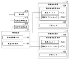
- FIG. 1 is a diagram showing an example of a ship 1 having a control device 14 for which setting is performed by the automatic setting device A of the first embodiment.
- FIG. 2 is a functional block diagram of the main part of the ship 1 shown in FIG.
- the ship 1 includes a hull 11, a ship propulsion device 12, a ship propulsion device 13, and a control device 14.
- the ship propulsion devices 12 and 13 generate the propulsive force of the ship 1.
- the ship propulsion device 12 is arranged on the right side of the rear 112 of the hull 11.
- the ship propulsion device 12 includes a ship propulsion device main body 12A and a bracket 12B.
- the bracket 12B is a mechanism for attaching the ship propulsion device 12 to the right side portion of the rear portion 112 of the hull 11.
- the ship propulsion device main body 12A is rotatably connected to the hull 11 about the steering shaft 12AX and is connected to the right side portion of the rear 112 of the hull 11 via the bracket 12B.
- the ship propulsion device main body 12A includes a propulsion unit 12A1 and a steering actuator 12A2.
- the propulsion unit 12A1 generates the propulsive force of the ship 1.
- the steering actuator 12A2 rotates the entire ship propulsion device main body 12A including the propulsion unit 12A1 with respect to the hull 11 around the steering shaft 12AX.
- the steering actuator 12A2 serves as a rudder.
- the ship propulsion device 13 is arranged on the left side portion of the rear 112 of the hull 11.
- the ship propulsion device 13 includes a ship propulsion device main body 13A and a bracket 13B.
- the bracket 13B is a mechanism for attaching the ship propulsion device 13 to the left side portion of the rear portion 112 of the hull 11.
- the ship propulsion device main body 13A is rotatably connected to the hull 11 about the steering shaft 13AX and is connected to the left side portion of the rear 112 of the hull 11 via the bracket 13B.
- the ship propulsion device main body 13A includes a propulsion unit 13A1 and a steering actuator 13A2.
- the propulsion unit 13A1 generates the propulsive force of the ship 1 in the same manner as the propulsion unit 12A1.
- the steering actuator 13A2 rotates the entire ship propulsion device main body 13A including the propulsion unit 13A1 with respect to the hull 11 around the steering shaft 13AX.
- the steering actuator 13A2 serves as a rudder.
- the ship propulsion devices 12 and 13 are outboard motors having propeller-specification propulsion units 12A1 and 13A1 driven by, for example, an engine (not shown).
- the ship propulsion devices 12 and 13 are an inboard unit having a propeller specification propulsion unit, an inboard / outboard unit having a propeller specification propulsion unit, a ship propulsion device having a water jet specification propulsion unit, and a pod drive type. It may be a ship propulsion device or the like.
- the ship propulsion devices 12 and 13 may be, for example, a ship propulsion device having a propulsion unit driven by an electric motor (not shown).
- the hull 11 includes a steering device 11A, a remote control device 11B, a remote control device 11C, an operation unit 11D, a ship position detection unit 11E, and a bow direction detection unit 11F.
- the hull 11 may not include the steering device 11A, the remote control device 11B, and the remote control device 11C. Further, in another example, the hull 11 may not include one of the ship position detection unit 11E and the bow direction detection unit 11F.
- the steering device 11A is a device that operates the steering actuators 12A2 and 13A2, and is, for example, a steering device having a steering wheel.
- the remote control device 11B is a device that receives an input operation for operating the propulsion unit 12A1, and has, for example, a remote control lever. The operator can change the magnitude and direction of the propulsive force generated by the propulsion unit 12A1 by operating the remote control device 11B.
- the remote control lever of the remote control device 11B includes a forward region in which the propulsion unit 12A1 generates a forward propulsive force for the ship 1, a reverse region in which the propulsion unit 12A1 generates a backward propulsive force for the ship 1, and a propulsion unit 12A1. Can be located in a neutral region that does not generate.
- the magnitude of the forward propulsive force of the ship 1 generated by the propulsion unit 12A1 changes according to the position of the remote control lever in the forward region. Further, the magnitude of the backward propulsive force of the ship 1 generated by the propulsion unit 12A1 changes according to the position of the remote control lever in the reverse region.
- the remote control device 11C is a device that receives an input operation for operating the propulsion unit 13A1, and is configured in the same manner as the remote control device 11B. That is, the operator can change the magnitude and direction of the propulsive force generated by the propulsion unit 13A1 by operating the remote control device 11C.
- the operation unit 11D is a device that operates the propulsion units 12A1 and 13A1 and the steering actuators 12A2 and 13A2. Specifically, the operation unit 11D receives an input operation for operating the propulsion units 12A1 and 13A1 and the steering actuators 12A2 and 13A2.
- the operation unit 11D is provided separately from the steering device 11A and the remote controller devices 11B and 11C.
- the operation unit 11D is composed of a joystick having a lever.
- the operator can not only operate the propulsion units 12A1 and 13A1 and the steering actuators 12A2 and 13A2, but also the operation unit.
- the propulsion units 12A1 and 13A1 and the steering actuators 12A2 and 13A2 can also be operated by operating the 11D (joystick).
- the ship position detection unit 11E detects the position of the ship 1.
- the ship position detection unit 11E includes, for example, a GPS (Global Positioning System) device.
- the GPS device calculates the position coordinates of the ship 1 by receiving signals from a plurality of GPS satellites.
- the bow direction detection unit 11F detects the direction of the bow 1B of the ship 1.
- the bow direction detection unit 11F includes, for example, a direction sensor.
- the direction sensor calculates the direction of the bow 1B by using, for example, the geomagnetism.
- the azimuth sensor may be a device (gyro compass) in which a finger north device and a vibration damping device are added to a gyroscope that rotates at high speed so as to always indicate north.
- the directional sensor may be a GPS compass that includes a plurality of GPS antennas and calculates the directional of the bow 1B from the relative positional relationship of the plurality of GPS antennas.
- the control device 14 has the propulsion unit 12A1 and the steering actuator 12A2 of the ship propulsion device 12 and the propulsion unit 13A1 and the steering actuator of the ship propulsion device 13 based on the input operation to the operation unit 11D. It controls 13A2. Specifically, the control device 14 controls the magnitude and direction of the propulsive force of the ship 1 generated by the propulsion units 12A1 and 13A1 and the steering actuators 12A2 and 13A2 based on the input operation to the operation unit 11D.
- the automatic setting device A (see FIG. 4) of the first embodiment is for the ship 1 in which the input operation to the operation unit 11D and the propulsion units 12A1, 13A1 and the steering actuators 12A2, 13A2 are generated. Set the correspondence with the magnitude and direction of the propulsive force.
- the control device 14 includes a movement route calculation unit 14A and a propulsion force calculation unit 14B.
- the movement route calculation unit 14A calculates the movement route of the operation unit 11D. Specifically, the movement path calculation unit 14A calculates the movement path of the tip of the joystick lever based on the position of the joystick lever detected by a sensor (not shown) such as a microswitch. Further, the movement path calculation unit 14A specifies the input operation received by the operation unit 11D based on the movement path of the tip of the lever of the joystick (that is, specifies what kind of input operation the operation unit 11D has received. To do).
- the propulsion force calculation unit 14B propulses the ship based on the movement path of the operation unit 11D calculated by the movement route calculation unit 14A (that is, based on the input operation to the operation unit 11D specified by the movement route calculation unit 14A).
- the propulsive force generated in the devices 12 and 13 is calculated.
- the propulsion force calculation unit 14B determines the magnitude and direction of the propulsion force of the ship 1 generated in the propulsion units 12A1 and 13A1 and the steering actuators 12A2 and 13A2 based on the input operation specified by the movement path calculation unit 14A. Is calculated.
- control device 14 causes the propulsion units 12A1, 13A1 and the steering actuator 12A2 so that the propulsion units 12A1, 13A1 and the steering actuators 12A2, 13A2 generate the propulsive force of the magnitude and direction calculated by the propulsion force calculation unit 14B.
- 13A2 is controlled.
- the propulsion units 12A1, 13A1 and the steering actuator 12A2 Set what kind of propulsive force is generated in 13A2.
- the operation unit 11D is configured so that the lever of the operation unit 11D (joystick) can be tilted and the lever can rotate about the central axis of the lever.
- the control device 14 turns the ship 1 clockwise on the spot and the front part 111 of the hull 11 is the rear part.
- the propulsion units 12A1 and 13A1 and the steering actuators 12A2 and 13A2 are controlled so as to move relative to the right with respect to 112. That is, in the automatic setting device A (see FIG.
- the ship 1 when the operation unit 11D receives an input operation for rotating the lever clockwise around the central axis of the lever, the ship 1 watches.
- the control device 14 is set so that the propulsion units 12A1 and 13A1 and the steering actuators 12A2 and 13A2 generate the propulsive force that turns around on the spot.
- the ship 1 does not turn clockwise on the spot, for example, the ship 1 makes a large right turn (having a radius of curvature). And turn right).
- the automatic setting device A turns the ship 1 clockwise on the spot by using the detection results of, for example, the ship position detection unit 11E and the bow direction detection unit 11F.
- the control device 14 is adjusted (that is, the magnitude and direction of the propulsive force generated by the propulsion units 12A1, 13A1 and the steering actuators 12A2, 13A2) are adjusted.
- the control device 14 When the operator rotates the lever counterclockwise around the central axis of the lever of the operation unit 11D, the control device 14 causes the ship 1 to turn counterclockwise on the spot and the front portion 111 of the hull 11. Controls the propulsion units 12A1, 13A1 and the steering actuators 12A2, 13A2 so that the lever moves relative to the rear 112 in the counterclockwise direction. That is, in the automatic setting device A (see FIG. 4) of the first embodiment, when the operation unit 11D receives an input operation for rotating the lever counterclockwise around the central axis of the lever, the ship 1 receives the input operation.
- the control device 14 is set so that the propulsion units 12A1 and 13A1 and the steering actuators 12A2 and 13A2 generate the propulsive force that turns counterclockwise on the spot.
- the ship 1 does not turn counterclockwise on the spot, for example, the ship 1 makes a large left turn (having a radius of curvature). And turn left).
- the automatic setting device A uses the detection results of, for example, the ship position detection unit 11E and the bow direction detection unit 11F, so that the ship 1 turns counterclockwise on the spot. Adjustment of the control device 14 (that is, adjustment of the magnitude and direction of the propulsive force generated by the propulsion units 12A1 and 13A1 and the steering actuators 12A2 and 13A2) is performed so as to turn.
- FIG. 3 is a diagram for explaining an example of the position of the operation unit 11D shown in FIG. 1 (specifically, the positions P1 to P9 of the tip of the lever of the joystick).
- the lever of the operation unit 11D (joystick) is not tilted. Therefore, the operation unit 11D (specifically, the tip of the joystick lever) is located at the position (neutral position) P1.
- the control device 14 does not generate the propulsive force of the ship 1 in the propulsion units 12A1 and 13A1 and the steering actuators 12A2 and 13A2.
- the position P1 is a position where the ship propulsion devices 12 and 13 do not generate the propulsive force of the ship 1.
- the ship propulsion device 12 when the operation unit 11D does not accept the input operation and the tip of the lever of the operation unit 11D is located at the position P1, the ship propulsion device 12 The control device 14 is set so that the 13 does not generate the propulsive force of the ship 1.
- the lever of the joystick is tilted to the right. Therefore, the tip of the joystick lever is located at the position P2 on the right side of the position P1.
- the control device 14 causes the propulsion units 12A1, 13A1 and the steering actuators 12A2, 13A2 to generate a propulsive force for moving the ship 1 to the right. That is, the position P2 is a position where the ship propulsion devices 12 and 13 generate a propulsive force for moving the ship 1 to the right (specifically, translational movement).
- the automatic setting device A (see FIG.
- the first embodiment translates the ship 1 to the right when the operation unit 11D receives an input operation for moving the tip of the lever from the position P1 to the position P2.
- the control device 14 is set so that the propulsion units 12A1 and 13A1 and the steering actuators 12A2 and 13A2 generate the propulsive force.
- the vessel 1 may not translate to the right, for example, to translate to the right forward or to the right to the rear. , It is possible to turn right.
- the automatic setting device A controls the ship 1 to move to the right by using the detection results of the ship position detection unit 11E, the bow direction detection unit 11F, and the like. Adjustment of the device 14 (that is, adjustment of the magnitude and direction of the propulsive force generated by the propulsion units 12A1, 13A1 and the steering actuators 12A2, 13A2) is performed.
- the lever of the joystick is tilted forward to the right. Therefore, the tip of the lever of the joystick is located at the position P3 on the right front side of the position P1.
- the control device 14 gives the propulsion units 12A1 and 13A1 and the steering actuators 12A2 and 13A2 a propulsive force for moving the ship 1 to the right and forward so as to form an acute angle ⁇ 3 with the left and right directions. generate. That is, the position P3 is a position where the ship propulsion devices 12 and 13 generate a propulsive force for moving the ship 1 forward to the right (translational movement).
- the automatic setting device A (see FIG.
- the first embodiment translates the ship 1 forward to the right when the operation unit 11D receives an input operation for moving the tip of the lever from the position P1 to the position P3.
- the control device 14 is set so that the propulsion units 12A1 and 13A1 and the steering actuators 12A2 and 13A2 generate the propulsive force to be caused.
- the automatic setting device A uses the detection results of, for example, the ship position detection unit 11E and the bow direction detection unit 11F, so that the ship 1 translates to the right forward. , Adjusting the control device 14 (that is, adjusting the magnitude and orientation of the propulsive force generated by the propulsion units 12A1, 13A1 and the steering actuators 12A2, 13A2).
- the lever of the joystick is tilted backward to the right. Therefore, the tip of the joystick lever is located at the position P4 on the right rear side of the position P1.
- the control device 14 exerts a propulsive force on the propulsion units 12A1 and 13A1 and the steering actuators 12A2 and 13A2 to move the ship 1 in the left-right direction and in the right-rear direction forming an acute angle ⁇ 4. generate. That is, the position P4 is a position where the ship propulsion devices 12 and 13 generate a propulsive force for moving the ship 1 backward to the right (translational movement).
- the automatic setting device A (see FIG.
- the first embodiment translates the ship 1 backward to the right when the operation unit 11D receives an input operation for moving the tip of the lever from the position P1 to the position P4.
- the control device 14 is set so that the propulsion units 12A1 and 13A1 and the steering actuators 12A2 and 13A2 generate the propulsive force to be caused.
- the automatic setting device A uses the detection results of, for example, the ship position detection unit 11E and the bow direction detection unit 11F, so that the ship 1 translates backward to the right. , Adjusting the control device 14 (that is, adjusting the magnitude and orientation of the propulsive force generated by the propulsion units 12A1, 13A1 and the steering actuators 12A2, 13A2).
- the lever of the joystick is tilted to the left. Therefore, the tip of the joystick lever is located at the position P5 on the left side of the position P1.
- the control device 14 causes the propulsion units 12A1, 13A1 and the steering actuators 12A2, 13A2 to generate a propulsive force for moving the ship 1 to the left. That is, the position P5 is a position where the ship propulsion devices 12 and 13 generate a propulsive force for moving the ship 1 to the left (translational movement).
- the automatic setting device A (see FIG.
- the first embodiment translates the ship 1 to the left when the operation unit 11D receives an input operation for moving the tip of the lever from the position P1 to the position P5.
- the control device 14 is set so that the propulsion units 12A1 and 13A1 and the steering actuators 12A2 and 13A2 generate the propulsive force.
- the vessel 1 may not translate to the left, for example, may translate to the left forward or translate to the left rearward. , It is possible to turn left.
- the automatic setting device A controls the ship 1 to move to the left by using the detection results of, for example, the ship position detection unit 11E and the bow direction detection unit 11F. Adjustment of the device 14 (that is, adjustment of the magnitude and direction of the propulsive force generated by the propulsion units 12A1, 13A1 and the steering actuators 12A2, 13A2) is performed.
- the lever of the joystick is tilted forward to the left. Therefore, the tip of the lever of the joystick is located at the position P6 on the left front side of the position P1.
- the control device 14 exerts a propulsive force on the propulsion units 12A1 and 13A1 and the steering actuators 12A2 and 13A2 to move the ship 1 to the left and forward at an acute angle ⁇ 6. generate. That is, the position P6 is a position where the ship propulsion devices 12 and 13 generate a propulsive force for moving the ship 1 forward to the left (translational movement).
- the automatic setting device A (see FIG.
- the first embodiment translates the ship 1 forward to the left when the operation unit 11D receives an input operation for moving the tip of the lever from the position P1 to the position P6.
- the control device 14 is set so that the propulsion units 12A1 and 13A1 and the steering actuators 12A2 and 13A2 generate the propulsive force to be caused.
- the automatic setting device A uses the detection results of, for example, the ship position detection unit 11E and the bow directional detection unit 11F, so that the ship 1 translates to the left forward. , Adjusting the control device 14 (that is, adjusting the magnitude and orientation of the propulsive force generated by the propulsion units 12A1, 13A1 and the steering actuators 12A2, 13A2).
- the lever of the joystick is tilted backward to the left. Therefore, the tip of the lever of the joystick is located at the position P7 on the left rear side of the position P1.
- the control device 14 exerts a propulsive force on the propulsion units 12A1 and 13A1 and the steering actuators 12A2 and 13A2 to move the ship 1 in the left-right direction and at an acute angle ⁇ 7. generate. That is, the position P7 is a position where the ship propulsion devices 12 and 13 generate a propulsive force for moving the ship 1 backward to the left (translational movement).
- the automatic setting device A (see FIG.
- the first embodiment translates the ship 1 backward to the left when the operation unit 11D receives an input operation for moving the tip of the lever from the position P1 to the position P7.
- the control device 14 is set so that the propulsion units 12A1 and 13A1 and the steering actuators 12A2 and 13A2 generate the propulsive force to be caused.
- the automatic setting device A uses the detection results of, for example, the ship position detection unit 11E and the bow direction detection unit 11F, so that the ship 1 translates to the left rearward. , Adjusting the control device 14 (that is, adjusting the magnitude and orientation of the propulsive force generated by the propulsion units 12A1, 13A1 and the steering actuators 12A2, 13A2).
- the lever of the joystick is tilted forward. Therefore, the tip of the lever of the joystick is located at the position P8 on the front side of the position P1.
- the control device 14 causes the propulsion units 12A1 and 13A1 and the steering actuators 12A2 and 13A2 to generate propulsive force for moving the ship 1 forward. That is, the position P8 is a position where the ship propulsion devices 12 and 13 generate a propulsive force for moving (advancing) the ship 1 forward.
- the automatic setting device A (see FIG.
- the first embodiment provides a propulsive force for advancing the ship 1 when the operation unit 11D receives an input operation for moving the tip of the lever from the position P1 to the position P8.
- the control device 14 is set so that the propulsion units 12A1 and 13A1 and the steering actuators 12A2 and 13A2 are generated.
- the vessel 1 does not move forward (moves forward), for example, moves forward to the right or moves forward to the left. , It is possible to turn right or turn left.
- the automatic setting device A adjusts the control device 14 (that is, by using the detection results of the ship position detection unit 11E, the bow direction detection unit 11F, etc., so that the ship 1 moves forward. , Adjusting the magnitude and orientation of the propulsive force generated by the propulsion units 12A1, 13A1 and the steering actuators 12A2, 13A2).
- the lever of the joystick is tilted backward. Therefore, the tip of the joystick lever is located at the position P9 behind the position P1.
- the control device 14 causes the propulsion units 12A1 and 13A1 and the steering actuators 12A2 and 13A2 to generate a propulsive force for moving the ship 1 backward. That is, the position P9 is a position where the ship propulsion devices 12 and 13 generate a propulsive force for moving (reverse) the ship 1 backward.
- the automatic setting device A (see FIG.
- the first embodiment provides a propulsive force for moving the ship 1 backward when the operation unit 11D receives an input operation for moving the tip of the lever from the position P1 to the position P9.
- the control device 14 is set so that the propulsion units 12A1 and 13A1 and the steering actuators 12A2 and 13A2 are generated.
- the vessel 1 does not move backward (moves backward), for example, moves backward to the right or moves backward to the left. , It is possible to turn right or turn left.
- the automatic setting device A adjusts the control device 14 (that is, by using the detection results of the ship position detection unit 11E, the bow direction detection unit 11F, etc., so that the ship 1 moves backward. , Adjusting the magnitude and orientation of the propulsive force generated by the propulsion units 12A1, 13A1 and the steering actuators 12A2, 13A2).
- the tip of the lever of the joystick having the automatic return function is located at the position P1.
- the tip of the lever of the joystick can be positioned at a position such as positions P1 to P9 according to the operation of the operator.
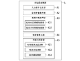
- FIG. 4 is a diagram showing an example of the automatic setting device A of the first embodiment.
- the automatic setting device A sets the setting of the control device 14 shown in FIGS. 1 and 2 (that is, the magnitude and direction of the propulsive force generated by the propulsion units 12A1, 13A1 and the steering actuators 12A2, 13A2). Setting) is performed automatically.
- the automatic setting device A includes an input operation setting unit A1, a target behavior acquisition unit A2, a ship information acquisition unit A3, an actual behavior calculation unit A4, and a propulsion force setting unit A5.
- the input operation setting unit A1 sets an input operation (for example, an input operation received by the operation unit 11D) for the operation unit 11D of the ship 1.
- the target behavior acquisition unit A2 acquires the target behavior of the ship 1 corresponding to the input operation set by the input operation setting unit A1.
- the ship information acquisition unit A3 acquires information on the position of the ship 1 and information on the direction of the ship 1 as ship information.
- the ship information acquisition unit A3 includes a ship position information acquisition unit A31 and a bow direction information acquisition unit A32.
- the ship position information acquisition unit A31 may be used, for example, in information about the current position of the ship 1 detected by the ship position detection unit 11E, for example, in a storage unit (not shown) of the ship 1 detected by the ship position detection unit 11E.
- the stored information (past log) regarding the position of the ship 1 in the past is acquired as the ship information.
- the bow direction information acquisition unit A32 is stored in, for example, information regarding the direction of the bow 1B of the current ship 1 detected by the bow direction detection unit 11F, for example, detected by the bow direction detection unit 11F and stored in, for example, a storage unit of the ship 1.
- Information (past log) regarding the direction of the bow 1B of the past ship 1 is acquired as ship information.
- the ship information acquisition unit A3 acquires information on the position of the ship 1 and information on the orientation of the ship 1 as ship information, but in another example, the ship information acquisition unit A3 Only one of the information regarding the position of the ship 1 and the information regarding the orientation of the ship 1 may be acquired as the ship information. Further, in the example shown in FIG. 4, the ship information acquisition unit A3 acquires the current ship information and the past ship information (past log), but in another example, the ship information acquisition unit A3 acquires the current ship. You may get only the information.
- the actual behavior calculation unit A4 calculates the actual behavior of the ship 1 based on the ship information acquired by the ship information acquisition unit A3.
- the actual behavior calculation unit A4 may include information on the current position of the ship 1 detected by the ship position detection unit 11E, a past detected by the ship position detection unit 11E and stored in, for example, a storage unit of the ship 1.
- the actual behavior of the ship 1 is calculated based on the information regarding the orientation of the bow 1B of the ship 1 of the ship 1.
- the propulsion force setting unit A5 sets the propulsion units 12A1, 13A1 and the steering actuator based on the actual behavior of the ship 1 calculated by the actual behavior calculation unit A4 and the target behavior of the ship 1 acquired by the target behavior acquisition unit A2. Set the magnitude and direction of the propulsive force generated by 12A2 and 13A2.
- the propulsion force setting unit A5 includes an initial propulsion force setting unit A51, a propulsion force change unit A52, and a set value storage unit A53.
- the initial propulsion force setting unit A51 is the magnitude of the propulsion force first generated by the propulsion units 12A1, 13A1 and the steering actuators 12A2, 13A2 after the input operation setting unit A1 sets the input operation for the operation unit 11D of the ship 1.
- the propulsion force changing unit A52 has the propulsion units 12A1, 13A1 and the steering actuator so that the actual behavior of the ship 1 calculated by the actual behavior calculation unit A4 approaches the target behavior of the ship 1 acquired by the target behavior acquisition unit A2. At least one of the magnitude and direction of the propulsive force generated by 12A2 and 13A2 is changed from the magnitude and direction of the initial propulsive force set by the initial propulsive force setting unit A51.
- the set value storage unit A53 determines the magnitude and direction of the propulsive force generated by the propulsion units 12A1 and 13A1 and the steering actuators 12A2 and 13A2 when the actual behavior of the ship 1 is included in the allowable range of the target behavior of the ship 1. Store as a propulsion setting value.
- the propulsion force setting unit A5 includes an initial propulsion force setting unit A51, a propulsion force change unit A52, and a set value storage unit A53, but in another example, the propulsion force setting unit A53.
- A5 includes an initial propulsion force setting unit A51 and a set value storage unit A53, and may not include a propulsion force change unit A52.
- the propulsion units 12A1, 13A1 and the steering actuators 12A2, 13A2 so that the actual behavior of the ship 1 calculated by the actual behavior calculation unit A4 approaches the target behavior of the ship 1 acquired by the target behavior acquisition unit A2.
- the process of changing at least one of the magnitude and the direction of the propulsive force generated by the operator is performed.
- the user of the automatic setting device A has the magnitude of the propulsive force generated by the propulsion units 12A1, 13A1 and the steering actuators 12A2, 13A2 when the ship 1 is turned clockwise on the spot.
- Let the automatic setting device A set the orientation and the magnitude and orientation of the propulsive force generated by the propulsion units 12A1, 13A1 and the steering actuators 12A2, 13A2 when the ship 1 is turned counterclockwise on the spot. .. Therefore, in the examples shown in FIGS. 1 to 4, "clockwise in-situ turning” and “counterclockwise in-situ turning” are automatically set as the target behavior of the ship 1, for example, by the user of the automatic setting device A. It is input to the setting device A.
- the user of the automatic setting device A has the magnitude of the propulsive force generated by the propulsion units 12A1, 13A1 and the steering actuators 12A2, 13A2 when the ship 1 is translated to the right.
- the automatic setting device A is made to set the magnitude and direction of the propulsive force generated by the propulsion units 12A1 and 13A1 and the steering actuators 12A2 and 13A2. Therefore, in the examples shown in FIGS.
- the user of the automatic setting device A has the magnitude of the propulsive force generated by the propulsion units 12A1, 13A1 and the steering actuators 12A2, 13A2 when the ship 1 is translated to the left.
- the automatic setting device A is made to set the magnitude and direction of the propulsive force generated by the propulsion units 12A1 and 13A1 and the steering actuators 12A2 and 13A2. Therefore, in the examples shown in FIGS.
- the user of the automatic setting device A sets the magnitude and direction of the propulsive force generated by the propulsion units 12A1 and 13A1 and the steering actuators 12A2 and 13A2 when the ship 1 is advanced.
- the automatic setting device A is made to set the magnitude and direction of the propulsive force generated by the propulsion units 12A1, 13A1 and the steering actuators 12A2, 13A2 when the ship 1 is moved backward. Therefore, in the examples shown in FIGS. 1 to 4, "forward" and "backward" are input to the automatic setting device A by, for example, the user of the automatic setting device A as the target behavior of the ship 1.
- the automatic setting device A is, for example, the target behavior of the ship 1 input to the automatic setting device A by the user of the automatic setting device A (“clockwise in-situ turning”, “Counterclockwise in-situ turn”, “rightward translational movement”, “right forward translational movement”, “right backward translational movement”, “leftward translational movement”, “left forward translational movement”, “left”
- start setting the magnitude and orientation of the propulsive force generated by the propulsion units 12A1, 13A1 and the steering actuators 12A2, 13A2 (setting of the control device 14) based on “translational movement backward", “forward”, “backward”). To do.
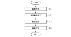
- FIG. 5 is a diagram showing an example of a main routine of processing executed by the automatic setting device A of the first embodiment.
- FIG. 6 is a diagram showing an example of a subroutine of processing executed by the automatic setting device A of the first embodiment.
- the automatic setting device A in step S1 of FIG. 5, the automatic setting device A generates propulsion units 12A1, 13A1 and steering actuators 12A2, 13A2 when the ship 1 is rotated clockwise on the spot. Setting the magnitude and direction of the propulsive force (setting of the control device 14), and the magnitude of the propulsive force generated by the propulsion units 12A1, 13A1 and the steering actuators 12A2, 13A2 when the ship 1 is turned counterclockwise on the spot. The orientation is set (the control device 14 is set).
- step S101 of FIG. 6 the magnitude and direction of the propulsive force generated by the propulsion units 12A1, 13A1 and the steering actuators 12A2, 13A2 when the ship 1 is rotated clockwise on the spot (control device).
- the input operation setting unit A1 sets an input operation for rotating the lever clockwise around the central axis of the lever of the operation unit 11D as an input operation for the operation unit 11D.
- the target behavior acquisition unit A2 corresponds to the input operation set in step S101 (the input operation of rotating the lever clockwise around the central axis of the lever of the operation unit 11D). Acquire "clockwise in-situ turning" as the target behavior.
- step S103 the initial propulsion force setting unit A51 of the propulsion force setting unit A5 is propelled after the input operation for rotating the lever clockwise around the central axis of the lever of the operation unit 11D is set in step S101.
- the magnitude and direction of the propulsive force first generated by the units 12A1 and 13A1 and the steering actuators 12A2 and 13A2 are set.
- the initial propulsion setting unit A51 sets the magnitude of the initial propulsion generated by the ship propulsion device 12 to the maximum value, and sets the direction of the initial propulsion generated by the ship propulsion device 12 to the rearward direction of the ship 1.
- the magnitude of the initial propulsive force generated by the ship propulsion device 13 is set to the maximum value, and the direction of the initial propulsive force generated by the ship propulsion device 13 is set to the forward direction of the ship 1.
- the ship propulsion devices 12 and 13 generate the initial propulsive force set in step S103. As a result, the ship 1 starts moving.
- the ship position detection unit 11E of the ship 1 detects the position of the ship 1, and the bow direction detection unit 11F detects the direction of the bow 1B of the ship 1.
- the ship position information acquisition unit A31 of the ship information acquisition unit A3 acquires information (ship information) regarding the current position of the ship 1 detected by the ship position detection unit 11E, and the bow orientation information acquisition unit.
- A32 acquires information (ship information) regarding the direction of the bow 1B of the current ship 1 detected by the bow direction detection unit 11F.
- the ship position information acquisition unit A31 of the ship information acquisition unit A3 is detected by the ship position detection unit 11E and the information regarding the current position of the ship 1 detected by the ship position detection unit 11E.
- information (ship information) regarding the position of the past ship 1 stored in the storage unit of the ship 1 is acquired, and the nose direction information acquisition unit A32 is the current ship detected by the nose direction detection unit 11F.
- step S105 the actual behavior calculation unit A4 calculates the actual behavior of the ship 1 based on the ship information acquired in step S104.
- step S106 the propulsion force changing unit A52 of the propulsion force setting unit A5 brings the propulsion unit so that the actual behavior of the ship 1 calculated in step S105 approaches the target behavior of the ship 1 acquired in step S102.
- At least one of the magnitude and direction of the propulsive force generated by the 12A1, 13A1 and the steering actuators 12A2 and 13A2 is changed from the magnitude and direction of the initial propulsive force set by the initial propulsive force setting unit A51.
- the ship propulsion devices 12 and 13 generate the propulsive force changed by the propulsion force changing unit A52.
- the actual behavior of the ship 1 changes.
- the change of the propulsive force in step S106 is repeated until the actual behavior of the vessel 1 is included in the allowable range of the target behavior of the vessel 1.
- the automatic setting device A does not execute step S106, and a worker (for example, a user of the automatic setting device A) performs a process corresponding to step S106 (the actual behavior of the ship 1 approaches the target behavior of the ship 1).
- the process of changing at least one of the magnitude and orientation of the propulsion force may be executed.
- the set value storage unit A53 of the propulsion force setting unit A5 has an allowable range in which the actual behavior of the ship 1 is the target behavior of the ship 1 (“clockwise in-situ turning”).
- the magnitude and direction of the propulsive force generated by the propulsion units 12A1, 13A1 and the steering actuators 12A2, 13A2 when included in (for example, the direction of the propulsive force generated by the ship propulsion device 12 is backward of the ship 1, the ship propulsion device 13
- the direction of the propulsive force generated by the ship 1 is forward) is stored as the propulsive force set value.
- the magnitude and direction of the propulsive force generated by the propulsion units 12A1, 13A1 and the steering actuators 12A2, 13A2 when the ship 1 is turned clockwise on the spot is completed (setting of the control device 14).
- the set value storage unit A53 then includes the actual behavior of the ship 1 within the permissible range of the target behavior of the ship 1 (“clockwise in-situ turning”).
- the propulsion unit 12A1, 13A1 and the steering actuators 12A2, 13A2 are reversed left and right (mirror image reversal), and the ship 1 is turned counterclockwise on the spot, the propulsion unit 12A1, It is stored as the magnitude and direction (propulsion force set value) of the propulsion force generated by the 13A1 and the steering actuators 12A2 and 13A2.
- the magnitude and direction of the propulsive force generated by the propulsion units 12A1, 13A1 and the steering actuators 12A2, 13A2 when the ship 1 is turned counterclockwise on the spot is completed (setting of the control device 14).
- the magnitude and direction of the propulsive force generated by the steering actuators 12A2 and 13A2 are set (setting of the control device 14).
- the automatic setting device A causes Vessel 1 to rotate counterclockwise in-situ.
- the magnitude and direction of the propulsive force generated by the 13A1 and the steering actuators 12A2 and 13A2 may be set (setting of the control device 14).
- the automatic setting device A generates propulsion units 12A1, 13A1 and steering actuators 12A2, 13A2 when the ship 1 is translated to the right.
- Setting the magnitude and direction of the propulsive force (setting of the control device 14) and the magnitude and direction of the propulsive force generated by the propulsion units 12A1, 13A1 and the steering actuators 12A2, 13A2 when the vessel 1 is translated to the right forward.
- Setting (setting of control device 14) and setting of magnitude and direction of propulsive force generated by propulsion units 12A1, 13A1 and steering actuators 12A2, 13A2 when translating the ship 1 backward to the right setting of control device 14).
- step S101 of FIG. 6, for example, when the ship 1 is translated to the right, the magnitude and direction of the propulsive force generated by the propulsion units 12A1, 13A1 and the steering actuators 12A2, 13A2 are set (control device 14).
- the input operation setting unit A1 sets an input operation for moving the tip of the lever of the operation unit 11D from the position P1 to the position P2 as an input operation for the operation unit 11D.
- the target behavior acquisition unit A2 corresponds to the input operation (input operation for moving the tip of the lever of the operation unit 11D from the position P1 to the position P2) set in step S101. As, "translational movement to the right" is acquired.
- step S103 the propulsion unit 12A1 is set after the initial propulsion setting unit A51 of the propulsion force setting unit A5 sets an input operation for moving the tip of the lever of the operation unit 11D from the position P1 to the position P2 in step S101.
- 13A1 and the steering actuators 12A2, 13A2 first set the magnitude and direction of the propulsive force (the magnitude and direction of the initial propulsive force) (for example, the direction of the propulsive force generated by the ship propulsion device 12 is set to that of the ship 1. Set it backwards, and set the direction of the propulsive force generated by the ship propulsion device 13 to the forward direction of the ship 1).
- the initial propulsion force setting unit A51 is a ship propulsion device stored as a propulsion force setting value in step S107 of FIG. 6 during execution of step S1 of FIG. 5 when the ship 1 is turning clockwise on the spot.
- the magnitude and direction of the propulsive force generated by each of 12 and 13 are set as the magnitude and direction of the initial propulsive force.
- the ship propulsion devices 12 and 13 generate the initial propulsive force set in step S103. As a result, the vessel 1 turns clockwise in place.
- the ship position detection unit 11E of the ship 1 detects the position of the ship 1, and the bow direction detection unit 11F detects the direction of the bow 1B of the ship 1.
- the ship position information acquisition unit A31 of the ship information acquisition unit A3 acquires information (ship information) regarding the position of the ship 1 detected by the ship position detection unit 11E, and the bow orientation information acquisition unit A32 , Acquires information (ship information) regarding the orientation of the bow 1B of the ship 1 detected by the bow orientation detection unit 11F.
- the actual behavior calculation unit A4 calculates the actual behavior of the ship 1 (“clockwise in-situ turning”) based on the ship information acquired in step S104.
- the propulsion force changing unit A52 of the propulsion force setting unit A5 has the actual behavior of the ship 1 (“clockwise in-situ turning”) calculated in step S105 of the ship 1 acquired in step S102. At least one of the magnitude and direction of the propulsive force generated by the propulsion units 12A1, 13A1 and the steering actuators 12A2, 13A2 is determined by the initial propulsion force setting unit A51 so as to approach the target behavior (“translational movement to the right”). Change from the set initial propulsion magnitude and direction.
- the propulsion force changing unit A52 changes the direction of the propulsive force generated by the ship propulsion device 12 from the rearward direction of the ship 1 to the right rearward direction, and changes the direction of the propulsive force generated by the ship propulsion device 13 forward of the ship 1. Change from to right forward.
- the ship propulsion devices 12 and 13 generate the propulsive force changed by the propulsion force changing unit A52.
- the actual behavior of the ship 1 changes.
- the change of the propulsive force in step S106 is repeated until the actual behavior of the vessel 1 is included in the allowable range of the target behavior of the vessel 1 (“translational movement to the right”).
- the automatic setting device A does not execute step S106, and a worker (for example, a user of the automatic setting device A) performs a process corresponding to step S106 (the actual behavior of the ship 1 approaches the target behavior of the ship 1).
- the process of changing at least one of the magnitude and orientation of the propulsion force may be executed.
- the set value storage unit A53 of the propulsion force setting unit A5 includes the actual behavior of the ship 1 within the allowable range of the target behavior of the ship 1 (“translational movement to the right”).
- the magnitude and direction of the propulsive force generated by the propulsion units 12A1 and 13A1 and the steering actuators 12A2 and 13A2 are stored as propulsive force set values.
- the setting of the magnitude and direction of the propulsive force generated by the propulsion units 12A1, 13A1 and the steering actuators 12A2, 13A2 when the ship 1 is translated to the right (setting of the control device 14) is completed.
- the set value storage unit A53 is then propelled when the actual behavior of the vessel 1 is within the permissible range of the target behavior of the vessel 1 (“translational movement to the right”).
- the propulsion units 12A1, 13A1 and the steering actuator 12A2 when the ship 1 is translated to the left by reversing the magnitude and direction of the propulsive force generated by the units 12A1, 13A1 and the steering actuators 12A2, 13A2 left and right (mirror image reversal).
- 13A2 is stored as the magnitude and direction (propulsion force set value) of the propulsive force generated.
- the setting of the magnitude and direction of the propulsive force generated by the propulsion units 12A1 and 13A1 and the steering actuators 12A2 and 13A2 when the ship 1 is translated to the left (setting of the control device 14) is completed.
- the propulsion units 12A1, 13A1 and the steering actuators 12A2, 13A2 are used when the ship 1 is translated to the left without actually moving to the left.
- the magnitude and direction of the generated propulsive force are set (setting of the control device 14).
- the ship 1 is set in the same manner as the setting of the magnitude and direction of the propulsive force (setting of the control device 14) generated by the propulsion units 12A1, 13A1 and the steering actuators 12A2, 13A2 when the ship 1 is translated to the right.
- the propulsion units 12A1, 13A1 and steering actuators 12A2, 13A2 move when the auto-setting device A translates to left.
- the magnitude and direction of the generated propulsive force may be set (setting of the control device 14).
- the magnitude and direction of the propulsive force generated by the propulsion units 12A1 and 13A1 and the steering actuators 12A2 and 13A2 when, for example, the ship 1 is translated to the right forward are set (controlled).
- the process for performing the setting of the device 14) is executed in the automatic setting device A. Specifically, first, in step S101 of FIG. 6, for example, when the ship 1 is translated to the right forward, the magnitude and direction of the propulsive force generated by the propulsion units 12A1, 13A1 and the steering actuators 12A2, 13A2 are set (control device).
- the input operation setting unit A1 sets an input operation for moving the tip of the lever of the operation unit 11D from the position P1 to the position P3 as an input operation for the operation unit 11D.
- the target behavior acquisition unit A2 corresponds to the input operation (input operation for moving the tip of the lever of the operation unit 11D from the position P1 to the position P3) set in step S101.
- “translational movement to the right forward” is acquired.
- the propulsion unit 12A1 is set after the initial propulsion setting unit A51 of the propulsion force setting unit A5 sets an input operation for moving the tip of the lever of the operation unit 11D from the position P1 to the position P3 in step S101.
- the initial propulsion force setting unit A51 generates the ship propulsion devices 12 and 13, respectively, when the ship 1 is translating to the right, which is stored as the propulsion force setting value in step S107 of FIG.
- the magnitude and direction of the propulsive force to be used are set as the magnitude and direction of the initial propulsive force.
- the ship propulsion devices 12 and 13 generate the initial propulsive force set in step S103. As a result, the vessel 1 translates to the right.
- the ship position detection unit 11E of the ship 1 detects the position of the ship 1, and the bow direction detection unit 11F detects the direction of the bow 1B of the ship 1.
- the ship position information acquisition unit A31 of the ship information acquisition unit A3 acquires information (ship information) regarding the position of the ship 1 detected by the ship position detection unit 11E, and the bow orientation information acquisition unit A32 , Acquires information (ship information) regarding the orientation of the bow 1B of the ship 1 detected by the bow orientation detection unit 11F.
- the actual behavior calculation unit A4 calculates the actual behavior (“translational movement to the right”) of the ship 1 based on the ship information acquired in step S104.
- the propulsion force changing unit A52 of the propulsion force setting unit A5 has the target of the ship 1 in which the actual behavior (“translational movement to the right”) of the ship 1 calculated in step S105 is acquired in step S102.
- At least one of the magnitude and direction of the propulsive force generated by the propulsion units 12A1, 13A1 and the steering actuators 12A2, 13A2 is set by the initial propulsion force setting unit A51 so as to approach the behavior (“translational movement to the right forward”). Change from the magnitude and orientation of the initial propulsion.
- the ship propulsion devices 12 and 13 generate the propulsive force changed by the propulsion force changing unit A52. As a result, the actual behavior of the ship 1 changes.
- step S106 The change of the propulsive force in step S106 is repeated until the actual behavior of the vessel 1 is included in the allowable range of the target behavior of the vessel 1 (“translational movement to the right forward”).
- the automatic setting device A does not execute step S106, and a worker (for example, a user of the automatic setting device A) performs a process corresponding to step S106 (the actual behavior of the ship 1 approaches the target behavior of the ship 1).
- the process of changing at least one of the magnitude and orientation of the propulsion force may be executed.
- step S107 the set value storage unit A53 of the propulsion force setting unit A5 sets the actual behavior of the ship 1 to the allowable range of the target behavior of the ship 1 (“translational movement forward to the right”).
- the magnitude and direction of the propulsive force generated by the propulsion units 12A1 and 13A1 and the steering actuators 12A2 and 13A2 when included are stored as propulsive force set values.
- the setting of the magnitude and direction of the propulsive force (setting of the control device 14) generated by the propulsion units 12A1, 13A1 and the steering actuators 12A2, 13A2 when the ship 1 is translated to the right forward is completed.
- the set value storage unit A53 uses the set value storage unit A53 when the actual behavior of the vessel 1 is included in the allowable range of the target behavior of the vessel 1 (“translational movement forward to the right”).
- the propulsion units 12A1, 13A1 and the steering actuators 12A2, 13A2 are left-right inverted (mirror image inverted) in the magnitude and direction of the propulsive force generated, and the propulsion units 12A1, 13A1 and steering are performed when the ship 1 is translated to the left forward. It is stored as the magnitude and direction (propulsive force set value) of the propulsive force generated by the actuators 12A2 and 13A2.
- the setting of the magnitude and direction of the propulsive force (setting of the control device 14) generated by the propulsion units 12A1, 13A1 and the steering actuators 12A2, 13A2 when the ship 1 is translated to the left forward is completed.
- the propulsion units 12A1, 13A1 and the steering actuator 12A2 when the ship 1 is translated to the left forward without actually moving to the left forward.
- the magnitude and direction of the propulsive force generated by 13A2 are set (setting of the control device 14).
- the ship 1 is set in the magnitude and direction of the propulsive force generated by the propulsion units 12A1, 13A1 and the steering actuators 12A2, 13A2 when the ship 1 is translated to the right forward (setting of the control device 14).
- the propulsion units 12A1, 13A1 and the steering actuator 12A2 when the automatic setting device A translates the vessel 1 to the left forward by actually translating the vessel 1 to the left forward (that is, based on the actual behavior of the vessel 1).
- the magnitude and direction of the propulsive force generated by 13A2 may be set (setting of the control device 14).
- the magnitude and direction of the propulsive force generated by the propulsion units 12A1 and 13A1 and the steering actuators 12A2 and 13A2 when, for example, the ship 1 is translated to the right rearward are set (controlled).
- the process for performing the setting of the device 14) is executed in the automatic setting device A. Specifically, first, in step S101 of FIG. 6, the magnitude and direction of the propulsive force generated by the propulsion units 12A1, 13A1 and the steering actuators 12A2, 13A2 when the ship 1 is translated to the right and rearward, for example, are set (control device).
- the input operation setting unit A1 sets an input operation for moving the tip of the lever of the operation unit 11D from the position P1 to the position P4 as an input operation for the operation unit 11D.
- the target behavior acquisition unit A2 corresponds to the input operation (input operation for moving the tip of the lever of the operation unit 11D from the position P1 to the position P4) set in step S101.
- “translational movement to the right and backward” is acquired.
- the propulsion unit 12A1 is set after the initial propulsion force setting unit A51 of the propulsion force setting unit A5 sets an input operation for moving the tip of the lever of the operation unit 11D from the position P1 to the position P4 in step S101.
- the initial propulsion force setting unit A51 generates the ship propulsion devices 12 and 13, which are stored as the propulsion force setting values in step S107 of FIG. 6 executed two times before, when the ship 1 is translating to the right.
- the magnitude and direction of the propulsive force to be used are set as the magnitude and direction of the initial propulsive force.
- the ship propulsion devices 12 and 13 generate the initial propulsive force set in step S103. As a result, the vessel 1 translates to the right.
- the ship position detection unit 11E of the ship 1 detects the position of the ship 1, and the bow direction detection unit 11F detects the direction of the bow 1B of the ship 1.
- the ship position information acquisition unit A31 of the ship information acquisition unit A3 acquires information (ship information) regarding the position of the ship 1 detected by the ship position detection unit 11E, and the bow orientation information acquisition unit A32 , Acquires information (ship information) regarding the orientation of the bow 1B of the ship 1 detected by the bow orientation detection unit 11F.
- the actual behavior calculation unit A4 calculates the actual behavior (“translational movement to the right”) of the ship 1 based on the ship information acquired in step S104.
- the propulsion force changing unit A52 of the propulsion force setting unit A5 has the target of the ship 1 in which the actual behavior (“translational movement to the right”) of the ship 1 calculated in step S105 is acquired in step S102.
- At least one of the magnitude and direction of the propulsive force generated by the propulsion units 12A1, 13A1 and the steering actuators 12A2, 13A2 is set by the initial propulsion force setting unit A51 so as to approach the behavior (“translational movement in the right rear direction”). Change from the magnitude and orientation of the initial propulsion.
- the ship propulsion devices 12 and 13 generate the propulsive force changed by the propulsion force changing unit A52. As a result, the actual behavior of the ship 1 changes.
- step S106 The change of the propulsive force in step S106 is repeated until the actual behavior of the vessel 1 is included in the allowable range of the target behavior of the vessel 1 (“translational movement to the right and backward”).
- the automatic setting device A does not execute step S106, and a worker (for example, a user of the automatic setting device A) performs a process corresponding to step S106 (the actual behavior of the ship 1 approaches the target behavior of the ship 1).
- the process of changing at least one of the magnitude and orientation of the propulsion force may be executed.
- step S107 the set value storage unit A53 of the propulsion force setting unit A5 sets the actual behavior of the ship 1 to the allowable range of the target behavior of the ship 1 (“translational movement to the right and backward”).
- the magnitude and direction of the propulsive force generated by the propulsion units 12A1 and 13A1 and the steering actuators 12A2 and 13A2 when included are stored as propulsive force set values.
- the setting of the magnitude and direction of the propulsive force (setting of the control device 14) generated by the propulsion units 12A1, 13A1 and the steering actuators 12A2, 13A2 when the ship 1 is translated to the right rearward is completed.
- the set value storage unit A53 uses the set value storage unit A53 when the actual behavior of the vessel 1 is included in the allowable range of the target behavior of the vessel 1 (“translational movement backward to the right”).
- the propulsion units 12A1, 13A1 and the steering actuators 12A2, 13A2 are left-right inverted (mirror image inverted) in the magnitude and direction of the propulsive force generated, and the propulsion units 12A1, 13A1 and steering are performed when the ship 1 is translated backward to the left. It is stored as the magnitude and direction (propulsive force set value) of the propulsive force generated by the actuators 12A2 and 13A2.
- the setting of the magnitude and direction of the propulsive force (setting of the control device 14) generated by the propulsion units 12A1, 13A1 and the steering actuators 12A2, 13A2 when the ship 1 is translated backward to the left is completed.
- the propulsion units 12A1, 13A1 and the steering actuator 12A2 when the ship 1 is translated backward to the left without actually moving backward to the left.
- the magnitude and direction of the propulsive force generated by 13A2 are set (setting of the control device 14).
- the ship 1 is set in the magnitude and direction of the propulsive force generated by the propulsion units 12A1, 13A1 and the steering actuators 12A2, 13A2 when the ship 1 is translated to the right rearward (setting of the control device 14).
- the propulsion units 12A1, 13A1 and the steering actuator 12A2 when the automatic setting device A translates the ship 1 backward to the left by actually moving the ship 1 backward to the left (that is, based on the actual behavior of the ship 1).
- the magnitude and direction of the propulsive force generated by 13A2 may be set (setting of the control device 14).
- step S3 of FIG. 5 the automatic setting device A of the propulsive force generated by the propulsion units 12A1, 13A1 and the steering actuators 12A2, 13A2 when advancing the ship 1.
- Set the size and orientation setting of the control device 14).
- step S101 of FIG. 6 for example, setting the magnitude and direction of the propulsive force generated by the propulsion units 12A1, 13A1 and the steering actuators 12A2, 13A2 when advancing the ship 1 (setting of the control device 14).
- the input operation setting unit A1 sets an input operation for moving the tip of the lever of the operation unit 11D from the position P1 to the position P8 as an input operation for the operation unit 11D.
- the target behavior acquisition unit A2 corresponds to the input operation (input operation for moving the tip of the lever of the operation unit 11D from position P1 to position P8) set in step S101. As, get "advance".
- the propulsion unit 12A1 is set after the initial propulsion force setting unit A51 of the propulsion force setting unit A5 sets an input operation for moving the tip of the lever of the operation unit 11D from the position P1 to the position P8 in step S101.
- 13A1 and the steering actuators 12A2, 13A2 set the magnitude and direction of the first propulsive force (the magnitude and direction of the initial propulsive force).
- the initial propulsion setting unit A51 sets the magnitude of the initial propulsion force generated by the ship propulsion device 12 to the maximum value, and sets the direction of the initial propulsion force generated by the ship propulsion device 12 to the forward direction of the ship 1.
- the magnitude of the initial propulsive force generated by the ship propulsion device 13 is set to the maximum value, and the direction of the initial propulsive force generated by the ship propulsion device 13 is set to the forward direction of the ship 1.
- the ship propulsion devices 12 and 13 generate the initial propulsive force set in step S103. As a result, ship 1 moves forward.
- step S104 the ship position information acquisition unit A31 of the ship information acquisition unit A3 acquires information (ship information) regarding the position of the ship 1 detected by the ship position detection unit 11E, and the bow orientation information acquisition unit A32 , Acquires information (ship information) regarding the orientation of the bow 1B of the ship 1 detected by the bow orientation detection unit 11F.
- step S105 the actual behavior calculation unit A4 calculates the actual behavior of the ship 1 based on the ship information acquired in step S104.
- step S106 the propulsion force changing unit A52 of the propulsion force setting unit A5 brings the propulsion unit so that the actual behavior of the ship 1 calculated in step S105 approaches the target behavior of the ship 1 acquired in step S102.
- At least one of the magnitude and direction of the propulsive force generated by the 12A1, 13A1 and the steering actuators 12A2, 13A2 is changed from the magnitude and direction of the initial propulsive force set by the initial propulsive force setting unit A51 (for example, ship propulsion).
- the magnitude of the forward propulsive force generated by the device 12 is reduced to an appropriate value
- the magnitude of the forward propulsive force generated by the ship propulsion device 13 is reduced to an appropriate value).
- the ship propulsion devices 12 and 13 generate the propulsive force changed by the propulsion force changing unit A52.
- the actual behavior of the ship 1 changes.
- the change of the propulsive force in step S106 is repeated until the actual behavior of the vessel 1 is included in the allowable range of the target behavior of the vessel 1.
- the automatic setting device A does not execute step S106, and a worker (for example, a user of the automatic setting device A) performs a process corresponding to step S106 (the actual behavior of the ship 1 approaches the target behavior of the ship 1).
- the process of changing at least one of the magnitude and orientation of the propulsion force may be executed.
- the set value storage unit A53 of the propulsion force setting unit A5 includes the actual behavior of the ship 1 within the allowable range of the target behavior (“advance”) of the ship 1.
- the magnitude and direction of the propulsive force generated by the propulsion units 12A1 and 13A1 and the steering actuators 12A2 and 13A2 are sometimes stored as propulsion force set values.
- the magnitude and direction of the propulsive force generated by the propulsion units 12A1, 13A1 and the steering actuators 12A2, 13A2 when the ship 1 is advanced is completed.
- the automatic setting device A determines the propulsive force generated by the propulsion units 12A1, 13A1 and the steering actuators 12A2, 13A2 when the ship 1 is moved backward. Set the size and orientation (setting of the control device 14).
- step S101 of FIG. 6 for example, the magnitude and direction of the propulsive force generated by the propulsion units 12A1, 13A1 and the steering actuators 12A2, 13A2 when the ship 1 is moved backward (setting of the control device 14).
- the input operation setting unit A1 sets an input operation for moving the tip of the lever of the operation unit 11D from the position P1 to the position P9 as an input operation for the operation unit 11D.
- the target behavior acquisition unit A2 corresponds to the input operation (input operation for moving the tip of the lever of the operation unit 11D from the position P1 to the position P9) set in step S101. To get "backward".
- the propulsion unit 12A1 is set after the initial propulsion force setting unit A51 of the propulsion force setting unit A5 sets an input operation for moving the tip of the lever of the operation unit 11D from the position P1 to the position P9 in step S101.
- 13A1 and the steering actuators 12A2, 13A2 set the magnitude and direction of the first propulsive force (magnitude and direction of the initial propulsive force).
- the initial propulsion setting unit A51 sets the magnitude of the initial propulsion generated by the ship propulsion device 12 to the maximum value, and sets the direction of the initial propulsion generated by the ship propulsion device 12 to the rearward direction of the ship 1.
- the magnitude of the initial propulsive force generated by the ship propulsion device 13 is set to the maximum value, and the direction of the initial propulsive force generated by the ship propulsion device 13 is set to the rearward direction of the ship 1.
- the ship propulsion devices 12 and 13 generate the initial propulsive force set in step S103. As a result, Vessel 1 moves backward.
- step S104 the ship position information acquisition unit A31 of the ship information acquisition unit A3 acquires information (ship information) regarding the position of the ship 1 detected by the ship position detection unit 11E, and the bow orientation information acquisition unit A32 , Acquires information (ship information) regarding the orientation of the bow 1B of the ship 1 detected by the bow orientation detection unit 11F.
- step S105 the actual behavior calculation unit A4 calculates the actual behavior of the ship 1 based on the ship information acquired in step S104.
- step S106 the propulsion force changing unit A52 of the propulsion force setting unit A5 brings the propulsion unit so that the actual behavior of the ship 1 calculated in step S105 approaches the target behavior of the ship 1 acquired in step S102.
- At least one of the magnitude and direction of the propulsive force generated by the 12A1, 13A1 and the steering actuators 12A2, 13A2 is changed from the magnitude and direction of the initial propulsive force set by the initial propulsive force setting unit A51 (for example, ship propulsion).
- the magnitude of the backward propulsion force generated by the device 12 is reduced to an appropriate value, and the magnitude of the backward propulsion force generated by the ship propulsion device 13 is reduced to an appropriate value).
- the ship propulsion devices 12 and 13 generate the propulsive force changed by the propulsion force changing unit A52.
- the actual behavior of the ship 1 changes.
- the change of the propulsive force in step S106 is repeated until the actual behavior of the vessel 1 is included in the allowable range of the target behavior of the vessel 1.
- the automatic setting device A does not execute step S106, and a worker (for example, a user of the automatic setting device A) performs a process corresponding to step S106 (the actual behavior of the ship 1 approaches the target behavior of the ship 1).
- the process of changing at least one of the magnitude and orientation of the propulsion force may be executed.
- the set value storage unit A53 of the propulsion force setting unit A5 includes the actual behavior of the ship 1 within the permissible range of the target behavior (“reverse”) of the ship 1.
- the magnitude and direction of the propulsive force generated by the propulsion units 12A1 and 13A1 and the steering actuators 12A2 and 13A2 are sometimes stored as propulsion force set values.
- the setting (setting of the control device 14) of the magnitude and direction of the propulsive force generated by the propulsion units 12A1, 13A1 and the steering actuators 12A2, 13A2 when the ship 1 is moved backward is completed.
- the target behavior of the ship 1 input to the automatic setting device A by the user of the automatic setting device A (“translational movement toward the right forward”, “translational movement toward the right rear”). “Translational movement”, “Translation movement to the right”, “Translation movement to the right forward”, “Translation movement to the right backward”, “Translation movement to the left”, “Translation movement to the left forward”, “Translation movement to the left backward”,
- the setting of the control device 14 that realizes "forward” and "backward" is completed.
- a process of changing the propulsive force generated by the ship propulsion devices 12 and 13 is executed so that the actual behavior of the ship 1 approaches the target behavior of the ship 1. .. That is, according to the automatic setting device A of the first embodiment, the operator performs all the work of changing the propulsive force generated by the ship propulsion devices 12 and 13 so that the actual behavior of the ship 1 approaches the target behavior of the ship 1. Does not have to be done. Further, in the automatic setting device A of the first embodiment, a process of storing the propulsive force generated by the ship propulsion devices 12 and 13 when the actual behavior of the ship 1 is included in the allowable range of the target behavior of the ship 1 is executed. Will be done.
- the setting of the control device 14 of the ship propulsion devices 12 and 13 is not entirely performed by the work of the operator, but is performed by the processing of the automatic setting device A.
- the operator does not have to perform all the setting work of the control device 14 of the ship propulsion devices 12 and 13, and the control device 14 of the ship propulsion devices 12 and 13 can be automatically set.
- the magnitude and direction of the propulsive force generated by each of the ship propulsion devices 12 and 13 when the ship 1 is turning clockwise on the spot is promoted.
- the input operation setting unit A1 sets an input operation for translating the ship 1 to the right as an input operation for the ship 1, and propulsion force.
- the ship propulsion devices 12 and 13 are generated when the ship 1 is turning clockwise on the spot, which is stored as the propulsion setting value by the setting value storage unit A53.
- the magnitude and direction of the propulsive force to be used is set as the magnitude and direction of the initial propulsive force. Therefore, in the first example of the automatic setting device A of the first embodiment, the magnitude and direction of the propulsive force generated by the ship propulsion devices 12 and 13 when the ship 1 is turning clockwise on the spot are determined. It can be used as it is as the magnitude and direction of the initial propulsive force for realizing the translational movement of the ship 1 in the clockwise direction.
- the magnitude and direction of the propulsive force generated by each of the ship propulsion devices 12 and 13 when the ship 1 is turning clockwise on the spot is set as the propulsive force.
- the input operation setting unit A1 sets an input operation for translating the ship 1 forward to the right as an input operation for the ship 1, and sets the propulsion force.
- Each of the ship propulsion devices 12 and 13 is generated when the ship 1 is turning clockwise on the spot, which is stored as a propulsion force set value by the set value storage unit A53 in the initial propulsion force setting unit A51 of the unit A5.
- the magnitude and orientation of the propulsion force may be set as the magnitude and orientation of the initial propulsion force.
- the magnitude and direction of the propulsive force generated by each of the ship propulsion devices 12 and 13 when the ship 1 is turning clockwise on the spot is the propulsive force.
- the input operation setting unit A1 sets an input operation for translating the ship 1 backward to the right as an input operation for the ship 1, and propulsion force.
- the ship propulsion devices 12 and 13 are generated when the ship 1 is turning clockwise on the spot.
- the magnitude and direction of the propulsive force to be applied may be set as the magnitude and direction of the initial propulsive force.
- the propulsive force generated by the propulsion units 12A1, 13A1 and the steering actuators 12A2, 13A2 when the automatic setting device A turns the ship 1 clockwise on the spot The size and orientation of the ship 1 are set (setting of the control device 14) first, but in the second example of the automatic setting device A of the first embodiment described later, the automatic setting device A turns the ship 1 counterclockwise.
- the magnitude and direction of the propulsive force generated by the propulsion units 12A1, 13A1 and the steering actuators 12A2, 13A2 when turning on the spot are first set (setting of the control device 14).
- the automatic setting device A sets the ship 1 Setting the magnitude and direction of the propulsive force generated by the propulsion units 12A1, 13A1 and the steering actuators 12A2, 13A2 when turning clockwise on the spot (setting of the control device 14), and turning the vessel 1 counterclockwise on the spot.
- the magnitude and direction of the propulsive force generated by the propulsion units 12A1 and 13A1 and the steering actuators 12A2 and 13A2 are set (setting of the control device 14).
- step S101 of FIG. 6 the magnitude and direction of the propulsive force generated by the propulsion units 12A1 and 13A1 and the steering actuators 12A2 and 13A2 when the ship 1 is turned counterclockwise on the spot is set (control).
- the input operation setting unit A1 sets an input operation for rotating the lever counterclockwise around the central axis of the lever of the operation unit 11D as an input operation for the operation unit 11D.
- the target behavior acquisition unit A2 corresponds to the input operation set in step S101 (the input operation of rotating the lever counterclockwise around the central axis of the lever of the operation unit 11D).
- step S103 after the initial propulsion force setting unit A51 of the propulsion force setting unit A5 is set in step S101, an input operation for rotating the lever counterclockwise around the central axis of the lever of the operation unit 11D is set.
- the magnitude and direction of the propulsive force first generated by the propulsion units 12A1, 13A1 and the steering actuators 12A2, 13A2 (the magnitude and direction of the initial propulsive force) are set.
- the initial propulsion setting unit A51 sets the magnitude of the initial propulsion force generated by the ship propulsion device 12 to the maximum value, and sets the direction of the initial propulsion force generated by the ship propulsion device 12 to the forward direction of the ship 1.
- the magnitude of the initial propulsive force generated by the ship propulsion device 13 is set to the maximum value, and the direction of the initial propulsive force generated by the ship propulsion device 13 is set to the rearward direction of the ship 1.
- the ship propulsion devices 12 and 13 generate the initial propulsive force set in step S103. As a result, the ship 1 starts moving.
- step S104 the ship position information acquisition unit A31 of the ship information acquisition unit A3 acquires information (ship information) regarding the position of the ship 1 detected by the ship position detection unit 11E, and the bow orientation information acquisition unit A32 , Acquires information (ship information) regarding the orientation of the bow 1B of the ship 1 detected by the bow orientation detection unit 11F.
- step S105 the actual behavior calculation unit A4 calculates the actual behavior of the ship 1 based on the ship information acquired in step S104.
- step S106 the propulsion force changing unit A52 of the propulsion force setting unit A5 brings the propulsion unit so that the actual behavior of the ship 1 calculated in step S105 approaches the target behavior of the ship 1 acquired in step S102. At least one of the magnitude and direction of the propulsive force generated by the 12A1, 13A1 and the steering actuators 12A2 and 13A2 is changed from the magnitude and direction of the initial propulsive force set by the initial propulsive force setting unit A51. Next, the ship propulsion devices 12 and 13 generate the propulsive force changed by the propulsion force changing unit A52. As a result, the actual behavior of the ship 1 changes.
- step S106 The change of the propulsive force in step S106 is repeated until the actual behavior of the vessel 1 is included in the allowable range of the target behavior of the vessel 1.
- the automatic setting device A does not execute step S106, and a worker (for example, a user of the automatic setting device A) performs a process corresponding to step S106 (the actual behavior of the ship 1 approaches the target behavior of the ship 1).
- the process of changing at least one of the magnitude and orientation of the propulsion force may be executed.
- the set value storage unit A53 of the propulsion force setting unit A5 allows the actual behavior of the ship 1 to be the target behavior of the ship 1 (“in-situ turning counterclockwise”).
- the magnitude and direction of the propulsive force generated by the propulsion units 12A1, 13A1 and the steering actuators 12A2, 13A2 when included in the range (for example, the direction of the propulsive force generated by the ship propulsion device 12 is forward of the ship 1, the ship propulsion device.
- the direction of the propulsive force generated by 13 is backward of the ship 1) is stored as the propulsive force set value.
- the magnitude and direction of the propulsive force generated by the propulsion units 12A1, 13A1 and the steering actuators 12A2, 13A2 when the ship 1 is turned counterclockwise on the spot is completed (setting of the control device 14).
- the set value storage unit A53 then includes the actual behavior of the ship 1 within the permissible range of the target behavior of the ship 1 (“counterclockwise in-situ turning”).
- the propulsion units 12A1, 13A1 and the steering actuators 12A2, 13A2 are left-right reversed (mirror image reversal) in the magnitude and direction of the propulsive force
- the propulsion unit 12A1 when the ship 1 is turned clockwise on the spot, It is stored as the magnitude and direction (propulsion force set value) of the propulsion force generated by the 13A1 and the steering actuators 12A2 and 13A2.
- the magnitude and direction of the propulsive force generated by the propulsion units 12A1, 13A1 and the steering actuators 12A2, 13A2 when the ship 1 is turned clockwise on the spot is completed (setting of the control device 14).
- the propulsion units 12A1, 13A1 and the steering actuator are used when the ship 1 is turned clockwise in-situ without actually turning clockwise in-situ.
- the magnitude and direction of the propulsive force generated by 12A2 and 13A2 are set (setting of the control device 14).
- the magnitude and orientation of the propulsion force generated by the propulsion units 12A1, 13A1 and the steering actuators 12A2, 13A2 when the ship 1 is turned counterclockwise in the counterclockwise direction are set (setting of the control device 14).
- the magnitude and direction of the propulsive force generated by the steering actuators 12A2 and 13A2 may be set (setting of the control device 14).
- the automatic setting device A generates propulsion units 12A1, 13A1 and steering actuators 12A2, 13A2 when the ship 1 is translated to the left.
- Setting the magnitude and direction of the propulsive force (setting of the control device 14) and the magnitude and direction of the propulsive force generated by the propulsion units 12A1, 13A1 and the steering actuators 12A2, 13A2 when the vessel 1 is translated to the left forward.
- Setting (setting of control device 14) and setting of magnitude and direction of propulsive force generated by propulsion units 12A1, 13A1 and steering actuators 12A2, 13A2 when translating the ship 1 backward to the left setting of control device 14).
- step S101 of FIG. 6 the magnitude and direction of the propulsive force generated by the propulsion units 12A1 and 13A1 and the steering actuators 12A2 and 13A2 when the ship 1 is translated to the left, for example, are set (control device 14).
- the input operation setting unit A1 sets an input operation for moving the tip of the lever of the operation unit 11D from the position P1 to the position P5 as an input operation for the operation unit 11D.
- the target behavior acquisition unit A2 corresponds to the input operation (input operation for moving the tip of the lever of the operation unit 11D from the position P1 to the position P5) set in step S101. As, "translational movement to the left" is acquired.
- step S103 the propulsion unit 12A1 is set after the initial propulsion setting unit A51 of the propulsion force setting unit A5 sets an input operation for moving the tip of the lever of the operation unit 11D from the position P1 to the position P5 in step S101.
- 13A1 and the steering actuators 12A2, 13A2 first set the magnitude and direction of the propulsive force (the magnitude and direction of the initial propulsive force) (for example, the direction of the propulsive force generated by the ship propulsion device 12 is set to that of the ship 1.
- the initial propulsion force setting unit A51 propulsion of the ship when the ship 1 is turning counterclockwise on the spot, which is stored as a propulsion force setting value in step S107 of FIG. 6 during the execution of step S1 of FIG.
- the magnitude and direction of the propulsive force generated by each of the devices 12 and 13 are set as the magnitude and direction of the initial propulsive force.
- the ship propulsion devices 12 and 13 generate the initial propulsive force set in step S103.
- the vessel 1 makes an in-situ turn counterclockwise.
- the ship position detection unit 11E of the ship 1 detects the position of the ship 1, and the bow direction detection unit 11F detects the direction of the bow 1B of the ship 1.
- the ship position information acquisition unit A31 of the ship information acquisition unit A3 acquires information (ship information) regarding the position of the ship 1 detected by the ship position detection unit 11E, and the bow orientation information acquisition unit A32 , Acquires information (ship information) regarding the orientation of the bow 1B of the ship 1 detected by the bow orientation detection unit 11F.
- the actual behavior calculation unit A4 calculates the actual behavior of the ship 1 (“counterclockwise in-situ turning”) based on the ship information acquired in step S104.
- step S106 the propulsion force changing unit A52 of the propulsion force setting unit A5 has acquired the actual behavior of the ship 1 (“counterclockwise in-situ turning”) calculated in step S105 in step S102. At least one of the magnitude and direction of the propulsive force generated by the propulsion units 12A1, 13A1 and the steering actuators 12A2, 13A2 so as to approach the target behavior of 1 (“translational movement to the left”) is set to the initial propulsive force setting unit A51. Change from the magnitude and orientation of the initial propulsion set by.
- the propulsion force changing unit A52 changes the direction of the propulsive force generated by the ship propulsion device 12 from the rearward direction of the ship 1 to the left forward direction, and changes the direction of the propulsive force generated by the ship propulsion device 13 to the forward direction of the ship 1. Change from to left backward.
- the ship propulsion devices 12 and 13 generate the propulsive force changed by the propulsion force changing unit A52.
- the actual behavior of the ship 1 changes.
- the change of the propulsive force in step S106 is repeated until the actual behavior of the vessel 1 is included in the allowable range of the target behavior of the vessel 1 (“translational movement to the left”).
- the automatic setting device A does not execute step S106, and a worker (for example, a user of the automatic setting device A) performs a process corresponding to step S106 (the actual behavior of the ship 1 approaches the target behavior of the ship 1).
- the process of changing at least one of the magnitude and orientation of the propulsion force may be executed.
- the set value storage unit A53 of the propulsion force setting unit A5 includes the actual behavior of the ship 1 within the permissible range of the target behavior of the ship 1 (“translational movement to the left”).
- the magnitude and direction of the propulsive force generated by the propulsion units 12A1 and 13A1 and the steering actuators 12A2 and 13A2 are stored as propulsive force set values.
- the setting of the magnitude and direction of the propulsive force generated by the propulsion units 12A1 and 13A1 and the steering actuators 12A2 and 13A2 when the ship 1 is translated to the left (setting of the control device 14) is completed.
- the set value storage unit A53 is then propelled when the actual behavior of the vessel 1 is within the permissible range of the target behavior of the vessel 1 (“translational movement to the left”).
- 13A2 is stored as the magnitude and direction of the propulsive force generated (propulsive force set value).
- the setting of the magnitude and direction of the propulsive force generated by the propulsion units 12A1, 13A1 and the steering actuators 12A2, 13A2 when the ship 1 is translated to the right (setting of the control device 14) is completed.
- the propulsion units 12A1, 13A1 and the steering actuators 12A2, 13A2 are used when the ship 1 is translated to the right without actually moving to the right.
- the magnitude and direction of the generated propulsive force are set (setting of the control device 14).
- the ship 1 is set in the same manner as the setting of the magnitude and direction of the propulsive force (setting of the control device 14) generated by the propulsion units 12A1, 13A1 and the steering actuators 12A2, 13A2 when the ship 1 is translated to the left.
- the propulsion units 12A1, 13A1 and steering actuators 12A2, 13A2 move when the automatic setting device A translates to right.
- the magnitude and direction of the generated propulsive force may be set (setting of the control device 14).
- the magnitude and direction of the propulsive force generated by the propulsion units 12A1 and 13A1 and the steering actuators 12A2 and 13A2 when, for example, the ship 1 is translated to the left forward are set (controlled).
- the process for performing the setting of the device 14) is executed in the automatic setting device A. Specifically, first, in step S101 of FIG. 6, for example, when the ship 1 is translated to the left forward, the magnitude and direction of the propulsive force generated by the propulsion units 12A1, 13A1 and the steering actuators 12A2, 13A2 are set (control device).
- the input operation setting unit A1 sets an input operation for moving the tip of the lever of the operation unit 11D from the position P1 to the position P6 as an input operation for the operation unit 11D.
- the target behavior acquisition unit A2 corresponds to the input operation (input operation for moving the tip of the lever of the operation unit 11D from the position P1 to the position P6) set in step S101.
- “translational movement to the left forward” is acquired.
- the propulsion unit 12A1 is set after the initial propulsion force setting unit A51 of the propulsion force setting unit A5 sets an input operation for moving the tip of the lever of the operation unit 11D from the position P1 to the position P6 in step S101.
- the initial propulsion force setting unit A51 generates the ship propulsion devices 12 and 13 when the ship 1 is translating to the left, which is stored as the propulsion force setting value in step S107 of FIG.
- the magnitude and direction of the propulsive force to be used are set as the magnitude and direction of the initial propulsive force.
- the ship propulsion devices 12 and 13 generate the initial propulsive force set in step S103. As a result, the vessel 1 translates to the left.
- the ship position detection unit 11E of the ship 1 detects the position of the ship 1, and the bow direction detection unit 11F detects the direction of the bow 1B of the ship 1.
- the ship position information acquisition unit A31 of the ship information acquisition unit A3 acquires information (ship information) regarding the position of the ship 1 detected by the ship position detection unit 11E, and the bow orientation information acquisition unit A32 , Acquires information (ship information) regarding the orientation of the bow 1B of the ship 1 detected by the bow orientation detection unit 11F.
- the actual behavior calculation unit A4 calculates the actual behavior of the ship 1 (“translational movement to the left”) based on the ship information acquired in step S104.
- the propulsion force changing unit A52 of the propulsion force setting unit A5 has the target of the ship 1 in which the actual behavior (“translational movement to the left”) of the ship 1 calculated in step S105 is acquired in step S102.
- At least one of the magnitude and direction of the propulsive force generated by the propulsion units 12A1, 13A1 and the steering actuators 12A2, 13A2 is set by the initial propulsion force setting unit A51 so as to approach the behavior (“translational movement toward the left forward”). Change from the magnitude and orientation of the initial propulsion.
- the ship propulsion devices 12 and 13 generate the propulsive force changed by the propulsion force changing unit A52. As a result, the actual behavior of the ship 1 changes.
- step S106 The change of the propulsive force in step S106 is repeated until the actual behavior of the vessel 1 is included in the allowable range of the target behavior of the vessel 1 (“translational movement to the left forward”).
- the automatic setting device A does not execute step S106, and a worker (for example, a user of the automatic setting device A) performs a process corresponding to step S106 (the actual behavior of the ship 1 approaches the target behavior of the ship 1).
- the process of changing at least one of the magnitude and orientation of the propulsion force may be executed.
- step S107 the set value storage unit A53 of the propulsion force setting unit A5 sets the actual behavior of the ship 1 to the allowable range of the target behavior of the ship 1 (“translational movement to the left forward”).
- the magnitude and direction of the propulsive force generated by the propulsion units 12A1 and 13A1 and the steering actuators 12A2 and 13A2 when included are stored as propulsive force set values.
- the setting of the magnitude and direction of the propulsive force (setting of the control device 14) generated by the propulsion units 12A1, 13A1 and the steering actuators 12A2, 13A2 when the ship 1 is translated to the left forward is completed.
- the set value storage unit A53 uses the set value storage unit A53 when the actual behavior of the vessel 1 is included in the allowable range of the target behavior of the vessel 1 (“translational movement to the left forward”).
- the propulsion units 12A1, 13A1 and the steering actuators 12A2, 13A2 are left-right inverted (mirror image inverted) in the magnitude and direction of the propulsive force generated, and the propulsion units 12A1, 13A1 and steering are performed when the ship 1 is translated to the right. It is stored as the magnitude and direction (propulsive force set value) of the propulsive force generated by the actuators 12A2 and 13A2.
- the setting of the magnitude and direction of the propulsive force (setting of the control device 14) generated by the propulsion units 12A1, 13A1 and the steering actuators 12A2, 13A2 when the ship 1 is translated to the right forward is completed.
- the propulsion units 12A1, 13A1 and the steering actuator 12A2 when the ship 1 is translated to the right forward without actually moving the ship 1 to the right forward.
- the magnitude and direction of the propulsive force generated by 13A2 are set (setting of the control device 14).
- the ship 1 is set in the magnitude and direction of the propulsive force generated by the propulsion units 12A1, 13A1 and the steering actuators 12A2, 13A2 when the ship 1 is translated to the left forward (setting of the control device 14).
- the propulsion units 12A1, 13A1 and the steering actuator 12A2 when the automatic setting device A translates the vessel 1 forward to the right by actually translating the vessel 1 to the right (that is, based on the actual behavior of the vessel 1).
- the magnitude and direction of the propulsive force generated by 13A2 may be set (setting of the control device 14).
- the magnitude and direction of the propulsive force generated by the propulsion units 12A1 and 13A1 and the steering actuators 12A2 and 13A2 when, for example, the ship 1 is translated backward to the left are set (controlled).
- the process for performing the setting of the device 14) is executed in the automatic setting device A. Specifically, first, in step S101 of FIG. 6, for example, when the ship 1 is translated backward to the left, the magnitude and direction of the propulsive force generated by the propulsion units 12A1, 13A1 and the steering actuators 12A2, 13A2 are set (control device).
- the input operation setting unit A1 sets an input operation for moving the tip of the lever of the operation unit 11D from the position P1 to the position P7 as an input operation for the operation unit 11D.
- the target behavior acquisition unit A2 corresponds to the input operation (input operation for moving the tip of the lever of the operation unit 11D from the position P1 to the position P7) set in step S101.
- “translational movement to the left backward” is acquired.
- the propulsion unit 12A1 is set after the initial propulsion force setting unit A51 of the propulsion force setting unit A5 sets an input operation for moving the tip of the lever of the operation unit 11D from the position P1 to the position P7 in step S101.
- the initial propulsion force setting unit A51 generates the ship propulsion devices 12 and 13, respectively, when the ship 1 is translating to the left, which is stored as the propulsion force setting value in step S107 of FIG. 6 executed two times before.
- the magnitude and direction of the propulsive force to be used are set as the magnitude and direction of the initial propulsive force.
- the ship propulsion devices 12 and 13 generate the initial propulsive force set in step S103. As a result, the vessel 1 translates to the left.
- the ship position detection unit 11E of the ship 1 detects the position of the ship 1, and the bow direction detection unit 11F detects the direction of the bow 1B of the ship 1.
- the ship position information acquisition unit A31 of the ship information acquisition unit A3 acquires information (ship information) regarding the position of the ship 1 detected by the ship position detection unit 11E, and the bow orientation information acquisition unit A32 , Acquires information (ship information) regarding the orientation of the bow 1B of the ship 1 detected by the bow orientation detection unit 11F.
- the actual behavior calculation unit A4 calculates the actual behavior of the ship 1 (“translational movement to the left”) based on the ship information acquired in step S104.
- the propulsion force changing unit A52 of the propulsion force setting unit A5 has the target of the ship 1 in which the actual behavior (“translational movement to the left”) of the ship 1 calculated in step S105 is acquired in step S102.
- At least one of the magnitude and direction of the propulsive force generated by the propulsion units 12A1, 13A1 and the steering actuators 12A2, 13A2 is set by the initial propulsion force setting unit A51 so as to approach the behavior (“translational movement backward to the left”). Change from the magnitude and orientation of the initial propulsion.
- the ship propulsion devices 12 and 13 generate the propulsive force changed by the propulsion force changing unit A52. As a result, the actual behavior of the ship 1 changes.
- step S106 The change of the propulsive force in step S106 is repeated until the actual behavior of the vessel 1 is included in the allowable range of the target behavior of the vessel 1 (“translational movement to the left backward”).
- the automatic setting device A does not execute step S106, and a worker (for example, a user of the automatic setting device A) performs a process corresponding to step S106 (the actual behavior of the ship 1 approaches the target behavior of the ship 1).
- the process of changing at least one of the magnitude and orientation of the propulsion force may be executed.
- step S107 the set value storage unit A53 of the propulsion force setting unit A5 sets the actual behavior of the ship 1 to the allowable range of the target behavior of the ship 1 (“translational movement backward to the left”).
- the magnitude and direction of the propulsive force generated by the propulsion units 12A1 and 13A1 and the steering actuators 12A2 and 13A2 when included are stored as propulsive force set values.
- the setting of the magnitude and direction of the propulsive force (setting of the control device 14) generated by the propulsion units 12A1, 13A1 and the steering actuators 12A2, 13A2 when the ship 1 is translated backward to the left is completed.
- the set value storage unit A53 then uses the set value storage unit A53 when the actual behavior of the vessel 1 is included in the allowable range of the target behavior of the vessel 1 (“translational movement backward to the left”).
- the propulsion units 12A1, 13A1 and the steering actuators 12A2, 13A2 are left-right inverted (mirror image inverted) in the magnitude and direction of the propulsive force generated, and the propulsion units 12A1, 13A1 and steering are performed when the ship 1 is translated backward to the right. It is stored as the magnitude and direction (propulsive force set value) of the propulsive force generated by the actuators 12A2 and 13A2.
- the setting of the magnitude and direction of the propulsive force (setting of the control device 14) generated by the propulsion units 12A1, 13A1 and the steering actuators 12A2, 13A2 when the ship 1 is translated to the right rearward is completed.
- the propulsion units 12A1, 13A1 and the steering actuator 12A2 when the ship 1 is translated to the right rearward without actually moving to the right rearward.
- the magnitude and direction of the propulsive force generated by 13A2 are set (setting of the control device 14).
- the ship 1 is set in the magnitude and direction of the propulsive force generated by the propulsion units 12A1, 13A1 and the steering actuators 12A2, 13A2 when the ship 1 is translated backward to the left (setting of the control device 14).
- the propulsion units 12A1, 13A1 and the steering actuator 12A2 when the automatic setting device A translates the ship 1 backward to the right by actually moving the ship 1 backward to the right (that is, based on the actual behavior of the ship 1).
- the magnitude and direction of the propulsive force generated by 13A2 may be set (setting of the control device 14).
- step S3 of FIG. 5 the automatic setting device A advances the propulsion unit 12A1 when advancing the ship 1.
- 13A1 and the steering actuators 12A2 and 13A2 are used to set the magnitude and direction of the propulsive force (setting of the control device 14).
- the automatic setting device A uses the propulsion unit 12A1 when moving the ship 1 backward.
- 13A1 and the steering actuators 12A2 and 13A2 are used to set the magnitude and direction of the propulsive force (setting of the control device 14).
- the target behavior of the ship 1 input to the automatic setting device A by the user of the automatic setting device A (“translational movement toward the right forward”, “translational movement toward the right rear”). “Translational movement”, “Translation movement to the right”, “Translation movement to the right forward”, “Translation movement to the right backward”, “Translation movement to the left”, “Translation movement to the left forward”, “Translation movement to the left backward”,
- the setting of the control device 14 that realizes "forward” and "backward" is completed.
- the initial propulsion force setting unit A51 of the propulsion force setting unit A5 is stored as a propulsion force set value by the set value storage unit A53, and when the ship 1 is turning counterclockwise on the spot, the ship propulsion device 12
- the magnitude and direction of the propulsive force generated by each of the thirteen are set as the magnitude and direction of the initial propulsive force. Therefore, in the second example of the automatic setting device A of the first embodiment, the magnitude and direction of the propulsive force generated by the ship propulsion devices 12 and 13 when the ship 1 is turning counterclockwise on the spot are determined.
- the magnitude and direction of the initial propulsive force for realizing the translational movement of the ship 1 to the left can be used as it is.
- the magnitude and direction of the propulsive force generated by each of the ship propulsion devices 12 and 13 when the ship 1 is turning counterclockwise on the spot is determined.
- the input operation setting unit A1 sets an input operation for translating the ship 1 to the left forward as an input operation for the ship 1, and propulsion force.
- the initial propulsion setting unit A51 of the setting unit A5 is stored as a propulsion force set value by the set value storage unit A53, and when the ship 1 is turning counterclockwise on the spot, each of the ship propulsion devices 12 and 13
- the magnitude and direction of the generated propulsive force may be set as the magnitude and direction of the initial propulsive force.
- the magnitude and direction of the propulsive force generated by each of the ship propulsion devices 12 and 13 when the ship 1 is turning counterclockwise in place is propelled.
- the input operation setting unit A1 sets an input operation for translating the ship 1 backward to the left as an input operation for the ship 1 and propels it.
- the initial propulsion setting unit A51 of the force setting unit A5 is stored as a propulsion force setting value by the set value storage unit A53, and when the ship 1 is turning counterclockwise on the spot, the ship propulsion devices 12 and 13, respectively.
- the magnitude and direction of the propulsive force generated by may be set as the magnitude and direction of the initial propulsive force.
- FIG. 7 is a diagram showing another example of the ship 1 having the control device 14 set by the automatic setting device A of the first embodiment.
- the operation unit 11D is composed of a joystick having a lever.
- the operation unit 11D is composed of a touch panel.
- the steering device 11A steering wheel
- the remote control devices 11B and 11C remote control lever
- the operator can not only operate the propulsion units 12A1 and 13A1 and the steering actuators 12A2 and 13A2, but also the operation unit.
- the propulsion units 12A1 and 13A1 and the steering actuators 12A2 and 13A2 can also be operated by operating the 11D (touch panel).
- the hull 11 may not include the steering device 11A, the remote control device 11B, and the remote control device 11C.
- the control device 14 sets the steering actuator 12A2 and the propulsion unit 12A1 of the ship propulsion device 12 and the steering actuator 13A2 and the propulsion unit 13A1 of the ship propulsion device 13 based on the input operation to the operation unit 11D.
- Control Specifically, the control device 14 controls the magnitude and direction of the propulsive force of the ship 1 generated by the propulsion units 12A1 and 13A1 and the steering actuators 12A2 and 13A2 based on, for example, a flick input operation to the operation unit 11D (touch panel).
- the flick input operation the operator, for example, presses the touch panel and slides the finger pressing the touch panel in a desired direction.
- the movement route calculation unit 14A calculates the movement route of the operation unit 11D. Specifically, the movement route calculation unit 14A calculates the movement route of the finger that the operator slides while pressing the touch panel.
- the propulsion force calculation unit 14B is generated by the ship propulsion devices 12 and 13 based on the movement path of the operation unit 11D (the movement path of the finger slid while pressing the touch panel) calculated by the movement path calculation unit 14A. Calculate the magnitude and direction of propulsion.
- the operation unit 11D is configured so that the flick input operation can be performed on the operation unit 11D (touch panel) and the rotation input operation can be performed.
- the operator performs a rotation input operation by, for example, sliding one finger in the circumferential direction while pressing the touch panel in a state where one finger is brought into contact with the touch panel and fixed as a center point.
- the control device 14 controls the propulsion units 12A1, 13A1 and the steering actuators 12A2, 13A2 so that the ship 1 turns to the right. To control.
- the control device 14 controls the propulsion units 12A1, 13A1 and the steering actuator 12A2 so that the ship 1 turns to the left. , 13A2 is controlled. Further, when the operator performs a flick input operation on the operation unit 11D (touch panel), the control device 14 moves in the direction in which the operator's finger is slid while maintaining the attitude of the hull 11.
- the propulsion units 12A1 and 13A1 and the steering actuators 12A2 and 13A2 are controlled so as to perform translational movement).
- the operation unit 11D When the operator does not perform a flick input operation on the operation unit 11D (touch panel) (that is, when the operator's finger does not touch the touch panel), the operation unit 11D is in the state shown in FIG. 3 (A). It becomes the same state as. As a result, the control device 14 does not generate the propulsive force of the ship 1 in the propulsion units 12A1 and 13A1 and the steering actuators 12A2 and 13A2.
- the ship 1 having the control device 14 set by the automatic setting device A of the first embodiment includes two ship propulsion devices 12 and 13.
- the ship 1 having the control device 14 set by the automatic setting device A of the second embodiment includes three or more ship propulsion devices (not shown).
- the automatic setting device A of the second embodiment is configured in the same manner as the automatic setting device A of the first embodiment shown in FIG. 4, except for the points described later. Therefore, according to the automatic setting device A of the second embodiment, the same effect as that of the automatic setting device A of the first embodiment described above can be obtained except for the points described later.
- the propulsion force setting unit A5 of the automatic setting device A of the second embodiment is based on the actual behavior of the ship 1 calculated by the actual behavior calculation unit A4 and the target behavior of the ship 1 acquired by the target behavior acquisition unit A2.
- the magnitude and direction of the propulsive force generated by three or more ship propulsion devices are set.
- the initial propulsion force setting unit A51 of the propulsion force setting unit A5 of the automatic setting device A of the second embodiment has three or more ships after the input operation for the operation unit 11D of the ship 1 is set by the input operation setting unit A1.
- the magnitude and direction of the propulsive force first generated by the propulsion device is set as the magnitude and direction of the initial propulsive force.
- the actual behavior of the ship 1 calculated by the actual behavior calculation unit A4 is acquired by the target behavior acquisition unit A2.
- At least one of the magnitudes and directions of the propulsive forces generated by the three or more ship propulsion devices is determined from the magnitude and direction of the initial propulsive forces set by the initial propulsion force setting unit A51 so as to approach the target behavior of. change.
- the set value storage unit A53 of the propulsion force setting unit A5 of the automatic setting device A of the second embodiment has three or more ship propulsion devices when the actual behavior of the ship 1 is included in the permissible range of the target behavior of the ship 1. The magnitude and direction of the propulsive force generated by the above are stored as the propulsive force set value.
- a process of changing the propulsive force generated by three or more ship propulsion devices is executed so that the actual behavior of the ship 1 approaches the target behavior of the ship 1. That is, according to the automatic setting device A of the second embodiment, all the work of changing the propulsive force generated by the three or more ship propulsion devices so that the actual behavior of the ship 1 approaches the target behavior of the ship 1 is performed. No need to do it. Further, in the automatic setting device A of the second embodiment, a process of storing the propulsive force generated by three or more ship propulsion devices when the actual behavior of the ship 1 is included in the allowable range of the target behavior of the ship 1 is performed. Will be executed.
- the setting of the control devices 14 of the three or more ship propulsion devices is not all performed by the work of the operator, but is performed by the processing of the automatic setting device A.
- the operator it is possible for the operator to automatically set the control devices 14 of the three or more ship propulsion devices without having to perform all the setting work of the control devices 14 of the three or more ship propulsion devices.
- the magnitude and direction of the propulsive force generated by each of the three or more ship propulsion devices when the ship 1 is turning clockwise on the spot is the propulsive force.
- the input operation setting unit A1 After the set value storage unit A53 of the setting unit A5 stores the propulsive force set value, the input operation setting unit A1 performs an input operation for translating the ship 1 to the right, forward right, or backward right as an input operation for the ship 1.
- the initial propulsive force setting unit A51 of the propulsion force setting unit A5 is set and stored as a propulsion force set value by the set value storage unit A53, when the ship 1 is turning clockwise on the spot, three or more ships.
- the magnitude and direction of the propulsive force generated by each of the propulsion devices is set as the magnitude and direction of the initial propulsive force. Therefore, in the first example of the automatic setting device A of the second embodiment, the magnitude and direction of the propulsive force generated by each of the three or more ship propulsion devices when the ship 1 is turning clockwise on the spot are determined. , It can be used as it is as the magnitude and direction of the initial propulsive force for realizing the translational movement of the ship 1 to the right, forward to the right, or backward to the right.
- the magnitude and direction of the propulsive force generated by each of the three or more ship propulsion devices when the ship 1 is turning counterclockwise on the spot Is stored as the propulsion force set value by the set value storage unit A53 of the propulsion force setting unit A5, and then the input operation setting unit A1 translates the ship 1 to the left, forward left, or rear left as an input operation for the ship 1.
- the initial propulsion force setting unit A51 of the propulsion force setting unit A5 is stored as the propulsion force setting value by the set value storage unit A53, and the ship 1 is turning counterclockwise on the spot.
- the magnitude and direction of the propulsive force generated by each of the one or more ship propulsion devices is set as the magnitude and direction of the initial propulsive force. Therefore, in the second example of the automatic setting device A of the second embodiment, the magnitude and direction of the propulsive force generated by each of the three or more ship propulsion devices when the ship 1 is turning counterclockwise on the spot. Can be used as it is as the magnitude and direction of the initial propulsive force for realizing the translational movement of the ship 1 to the left, forward to the left, or backward to the left.
- a computer-readable recording medium by recording a program for realizing these functions on the recording medium. It may be realized by loading the program into a computer system and executing it.
- the term "computer system” as used herein includes hardware such as an OS and peripheral devices.
- the "computer-readable recording medium” refers to a portable medium such as a flexible disk, a magneto-optical disk, a ROM, or a CD-ROM, or a storage unit such as a hard disk built in a computer system.
- a "computer-readable recording medium” is a communication line for transmitting a program via a network such as the Internet or a communication line such as a telephone line, and dynamically holds the program for a short period of time. It may also include a program that holds a program for a certain period of time, such as a volatile memory inside a computer system that serves as a server or a client in that case. Further, the above-mentioned program may be for realizing a part of the above-mentioned functions, and may further realize the above-mentioned functions in combination with a program already recorded in the computer system.
- a ... Automatic setting device A1 ... Input operation setting unit, A2 ... Target behavior acquisition unit, A3 ... Ship information acquisition unit, A31 ... Ship position information acquisition unit, A32 ... Ship nose orientation information acquisition unit, A4 ... Actual behavior calculation unit, A5 ... Propulsion force setting unit, A51 ... Initial propulsion force setting unit, A52 ... Propulsion force change unit, A53 ... Set value storage unit, 1 ... Ship, 11 ... Hull, 111 ... Front, 112 ... Rear, 11A ... Steering device , 11B ... remote control device, 11C ... remote control device, 11D ... operation unit, P1 ... position, P2 ... position, P3 ... position, P4 ... position, P5 ...
Landscapes
- Chemical & Material Sciences (AREA)
- Engineering & Computer Science (AREA)
- Combustion & Propulsion (AREA)
- Mechanical Engineering (AREA)
- Ocean & Marine Engineering (AREA)
- Control Of Position, Course, Altitude, Or Attitude Of Moving Bodies (AREA)
- Mechanical Control Devices (AREA)
Abstract
Priority Applications (3)
| Application Number | Priority Date | Filing Date | Title |
|---|---|---|---|
| EP20817763.4A EP3981682A4 (fr) | 2019-06-06 | 2020-06-05 | Dispositif de réglage automatique, procédé de réglage automatique et programme |
| JP2021524913A JP7157945B2 (ja) | 2019-06-06 | 2020-06-05 | 自動設定装置、自動設定方法およびプログラム |
| US17/616,297 US11958583B2 (en) | 2019-06-06 | 2020-06-05 | Automatic setting device, automatic setting method, and program |
Applications Claiming Priority (2)
| Application Number | Priority Date | Filing Date | Title |
|---|---|---|---|
| JP2019106523 | 2019-06-06 | ||
| JP2019-106523 | 2019-06-06 |
Publications (1)
| Publication Number | Publication Date |
|---|---|
| WO2020246568A1 true WO2020246568A1 (fr) | 2020-12-10 |
Family
ID=73652935
Family Applications (1)
| Application Number | Title | Priority Date | Filing Date |
|---|---|---|---|
| PCT/JP2020/022229 Ceased WO2020246568A1 (fr) | 2019-06-06 | 2020-06-05 | Dispositif de réglage automatique, procédé de réglage automatique et programme |
Country Status (4)
| Country | Link |
|---|---|
| US (1) | US11958583B2 (fr) |
| EP (1) | EP3981682A4 (fr) |
| JP (1) | JP7157945B2 (fr) |
| WO (1) | WO2020246568A1 (fr) |
Citations (8)
| Publication number | Priority date | Publication date | Assignee | Title |
|---|---|---|---|---|
| JPH0130988B2 (fr) | 1986-01-24 | 1989-06-22 | Tobishima Construct Co Ltd | |
| JP2004303085A (ja) * | 2003-03-31 | 2004-10-28 | Fuzzy Logic Systems | 船舶等の制御装置及び方法 |
| JP2005145438A (ja) * | 2003-10-22 | 2005-06-09 | Yamaha Motor Co Ltd | 航走制御装置、それを備えた操船支援システムおよび船舶、ならびに航走制御方法 |
| JP2008137545A (ja) * | 2006-12-04 | 2008-06-19 | Tokimec Inc | 船舶用自動操舵装置 |
| JP2014076758A (ja) | 2012-10-11 | 2014-05-01 | Suzuki Motor Corp | 船舶の移動中心推定方法及びシステム |
| JP5764411B2 (ja) | 2011-06-30 | 2015-08-19 | ヤンマー株式会社 | 船舶操船装置 |
| US9764810B1 (en) * | 2015-06-23 | 2017-09-19 | Bruswick Corporation | Methods for positioning multiple trimmable marine propulsion devices on a marine vessel |
| JP2019106523A (ja) | 2017-12-11 | 2019-06-27 | サムソン エレクトロ−メカニックス カンパニーリミテッド. | インダクター及びその製造方法 |
Family Cites Families (12)
| Publication number | Priority date | Publication date | Assignee | Title |
|---|---|---|---|---|
| JP3677274B2 (ja) * | 2003-03-31 | 2005-07-27 | 財団法人ファジィシステム研究所 | 制御装置及び方法 |
| US6994046B2 (en) | 2003-10-22 | 2006-02-07 | Yamaha Hatsudoki Kabushiki Kaisha | Marine vessel running controlling apparatus, marine vessel maneuvering supporting system and marine vessel each including the marine vessel running controlling apparatus, and marine vessel running controlling method |
| US7267068B2 (en) * | 2005-10-12 | 2007-09-11 | Brunswick Corporation | Method for maneuvering a marine vessel in response to a manually operable control device |
| US8807059B1 (en) * | 2011-09-08 | 2014-08-19 | Brunswick Corporation | Marine vessels and systems for laterally maneuvering marine vessels |
| JP5982716B2 (ja) * | 2012-08-08 | 2016-08-31 | ヤマハ発動機株式会社 | 船舶推進制御装置、船舶推進装置および船舶 |
| JP2014073700A (ja) * | 2012-10-02 | 2014-04-24 | Yamaha Motor Co Ltd | 船舶推進システム及び船舶推進機の制御方法 |
| JP2015116847A (ja) * | 2013-12-16 | 2015-06-25 | ヤマハ発動機株式会社 | 船舶推進システムおよびそれを備えた船舶 |
| US9598160B2 (en) * | 2015-06-23 | 2017-03-21 | Brunswick Corporation | Systems and methods for automatically controlling attitude of a marine vessel with trim devices |
| CN105675195B (zh) * | 2016-02-03 | 2018-04-24 | 中国海洋石油总公司 | 基于船舶姿态测量的工程船作业实时分析系统 |
| JP6430985B2 (ja) * | 2016-03-25 | 2018-11-28 | ヤンマー株式会社 | 操船装置及びそれを備えた船舶 |
| JP6430988B2 (ja) * | 2016-03-31 | 2018-11-28 | ヤンマー株式会社 | 操船装置 |
| JP6831459B2 (ja) * | 2016-11-14 | 2021-02-17 | ボルボ ペンタ コーポレーションVolvo Penta Corporation | 複数の推進ユニットを備えた船舶を操作する方法 |
-
2020
- 2020-06-05 US US17/616,297 patent/US11958583B2/en active Active
- 2020-06-05 WO PCT/JP2020/022229 patent/WO2020246568A1/fr not_active Ceased
- 2020-06-05 EP EP20817763.4A patent/EP3981682A4/fr not_active Withdrawn
- 2020-06-05 JP JP2021524913A patent/JP7157945B2/ja active Active
Patent Citations (8)
| Publication number | Priority date | Publication date | Assignee | Title |
|---|---|---|---|---|
| JPH0130988B2 (fr) | 1986-01-24 | 1989-06-22 | Tobishima Construct Co Ltd | |
| JP2004303085A (ja) * | 2003-03-31 | 2004-10-28 | Fuzzy Logic Systems | 船舶等の制御装置及び方法 |
| JP2005145438A (ja) * | 2003-10-22 | 2005-06-09 | Yamaha Motor Co Ltd | 航走制御装置、それを備えた操船支援システムおよび船舶、ならびに航走制御方法 |
| JP2008137545A (ja) * | 2006-12-04 | 2008-06-19 | Tokimec Inc | 船舶用自動操舵装置 |
| JP5764411B2 (ja) | 2011-06-30 | 2015-08-19 | ヤンマー株式会社 | 船舶操船装置 |
| JP2014076758A (ja) | 2012-10-11 | 2014-05-01 | Suzuki Motor Corp | 船舶の移動中心推定方法及びシステム |
| US9764810B1 (en) * | 2015-06-23 | 2017-09-19 | Bruswick Corporation | Methods for positioning multiple trimmable marine propulsion devices on a marine vessel |
| JP2019106523A (ja) | 2017-12-11 | 2019-06-27 | サムソン エレクトロ−メカニックス カンパニーリミテッド. | インダクター及びその製造方法 |
Non-Patent Citations (1)
| Title |
|---|
| See also references of EP3981682A4 |
Also Published As
| Publication number | Publication date |
|---|---|
| US20220306262A1 (en) | 2022-09-29 |
| EP3981682A1 (fr) | 2022-04-13 |
| EP3981682A4 (fr) | 2023-07-26 |
| US11958583B2 (en) | 2024-04-16 |
| JP7157945B2 (ja) | 2022-10-21 |
| JPWO2020246568A1 (fr) | 2020-12-10 |
Similar Documents
| Publication | Publication Date | Title |
|---|---|---|
| US10640190B1 (en) | System and method for controlling course of a marine vessel | |
| US10775808B2 (en) | Boat maneuvering control method for boat and boat maneuvering control system for boat | |
| CN112351936B (zh) | 一种操纵杆装置、船舶推进控制系统和船舶 | |
| EP4516658A1 (fr) | Système de propulsion marine, procédé de commande associé et navire | |
| EP4177152A1 (fr) | Système de propulsion marine | |
| US20130072076A1 (en) | Method for maneuvering a yacht | |
| JP7157945B2 (ja) | 自動設定装置、自動設定方法およびプログラム | |
| WO2023286622A1 (fr) | Système d'aide à la mise à l'eau de navire, dispositif de commande de navire, procédé d'aide à la mise à l'eau de navire et programme | |
| JP7324995B2 (ja) | 船外機用制御装置、船外機用制御方法およびプログラム | |
| US11834143B2 (en) | Control device for outboard motor, control method for outboard motor, and program | |
| JP7162199B2 (ja) | 船外機用制御装置、船外機用制御方法およびプログラム | |
| US12332646B1 (en) | Steering control system of marine vessel, marine vessel and steering control method of marine vessel | |
| JP7266186B2 (ja) | 船舶推進装置用制御装置、船舶推進装置用制御方法およびプログラム | |
| JP7588326B2 (ja) | 船舶推進装置用制御装置、船舶推進装置用制御方法およびプログラム | |
| JP7687880B2 (ja) | 船舶制御システム、船舶制御装置、船舶制御方法およびプログラム | |
| WO2020246574A1 (fr) | Dispositif de commande de dispositif de propulsion du navire, procédé de commande de dispositif de propulsion du navire, et programme | |
| US20250050990A1 (en) | Marine propulsion system, control method therefor, and marine vessel | |
| WO2021251382A1 (fr) | Navire, dispositif de commande de navire, procédé de commande de navire et programme | |
| JP2022066156A (ja) | 船舶制御システム及び船舶 |
Legal Events
| Date | Code | Title | Description |
|---|---|---|---|
| 121 | Ep: the epo has been informed by wipo that ep was designated in this application |
Ref document number: 20817763 Country of ref document: EP Kind code of ref document: A1 |
|
| ENP | Entry into the national phase |
Ref document number: 2021524913 Country of ref document: JP Kind code of ref document: A |
|
| NENP | Non-entry into the national phase |
Ref country code: DE |
|
| WWE | Wipo information: entry into national phase |
Ref document number: 2020817763 Country of ref document: EP |
|
| WWW | Wipo information: withdrawn in national office |
Ref document number: 2020817763 Country of ref document: EP |