WO2020250512A1 - Dispositif de planification d'itinéraire, procédé de planification d'itinéraire, et système de planification d'itinéraire - Google Patents
Dispositif de planification d'itinéraire, procédé de planification d'itinéraire, et système de planification d'itinéraire Download PDFInfo
- Publication number
- WO2020250512A1 WO2020250512A1 PCT/JP2020/010217 JP2020010217W WO2020250512A1 WO 2020250512 A1 WO2020250512 A1 WO 2020250512A1 JP 2020010217 W JP2020010217 W JP 2020010217W WO 2020250512 A1 WO2020250512 A1 WO 2020250512A1
- Authority
- WO
- WIPO (PCT)
- Prior art keywords
- vehicle
- route
- unit
- stopped
- moving
- Prior art date
- Legal status (The legal status is an assumption and is not a legal conclusion. Google has not performed a legal analysis and makes no representation as to the accuracy of the status listed.)
- Ceased
Links
Images


Classifications
-
- B—PERFORMING OPERATIONS; TRANSPORTING
- B60—VEHICLES IN GENERAL
- B60L—PROPULSION OF ELECTRICALLY-PROPELLED VEHICLES; SUPPLYING ELECTRIC POWER FOR AUXILIARY EQUIPMENT OF ELECTRICALLY-PROPELLED VEHICLES; ELECTRODYNAMIC BRAKE SYSTEMS FOR VEHICLES IN GENERAL; MAGNETIC SUSPENSION OR LEVITATION FOR VEHICLES; MONITORING OPERATING VARIABLES OF ELECTRICALLY-PROPELLED VEHICLES; ELECTRIC SAFETY DEVICES FOR ELECTRICALLY-PROPELLED VEHICLES
- B60L58/00—Methods or circuit arrangements for monitoring or controlling batteries or fuel cells, specially adapted for electric vehicles
- B60L58/10—Methods or circuit arrangements for monitoring or controlling batteries or fuel cells, specially adapted for electric vehicles for monitoring or controlling batteries
- B60L58/12—Methods or circuit arrangements for monitoring or controlling batteries or fuel cells, specially adapted for electric vehicles for monitoring or controlling batteries responding to state of charge [SoC]
- B60L58/13—Maintaining the SoC within a determined range
-
- G—PHYSICS
- G01—MEASURING; TESTING
- G01C—MEASURING DISTANCES, LEVELS OR BEARINGS; SURVEYING; NAVIGATION; GYROSCOPIC INSTRUMENTS; PHOTOGRAMMETRY OR VIDEOGRAMMETRY
- G01C21/00—Navigation; Navigational instruments not provided for in groups G01C1/00 - G01C19/00
- G01C21/20—Instruments for performing navigational calculations
-
- G—PHYSICS
- G01—MEASURING; TESTING
- G01C—MEASURING DISTANCES, LEVELS OR BEARINGS; SURVEYING; NAVIGATION; GYROSCOPIC INSTRUMENTS; PHOTOGRAMMETRY OR VIDEOGRAMMETRY
- G01C21/00—Navigation; Navigational instruments not provided for in groups G01C1/00 - G01C19/00
- G01C21/26—Navigation; Navigational instruments not provided for in groups G01C1/00 - G01C19/00 specially adapted for navigation in a road network
- G01C21/34—Route searching; Route guidance
- G01C21/3453—Special cost functions, i.e. other than distance or default speed limit of road segments
- G01C21/3461—Preferred or disfavoured areas, e.g. dangerous zones, toll or emission zones, intersections, manoeuvre types or segments such as motorways, toll roads or ferries
-
- G—PHYSICS
- G01—MEASURING; TESTING
- G01C—MEASURING DISTANCES, LEVELS OR BEARINGS; SURVEYING; NAVIGATION; GYROSCOPIC INSTRUMENTS; PHOTOGRAMMETRY OR VIDEOGRAMMETRY
- G01C21/00—Navigation; Navigational instruments not provided for in groups G01C1/00 - G01C19/00
- G01C21/26—Navigation; Navigational instruments not provided for in groups G01C1/00 - G01C19/00 specially adapted for navigation in a road network
- G01C21/34—Route searching; Route guidance
- G01C21/3453—Special cost functions, i.e. other than distance or default speed limit of road segments
- G01C21/3469—Fuel consumption; Energy use; Emission aspects
-
- G—PHYSICS
- G01—MEASURING; TESTING
- G01C—MEASURING DISTANCES, LEVELS OR BEARINGS; SURVEYING; NAVIGATION; GYROSCOPIC INSTRUMENTS; PHOTOGRAMMETRY OR VIDEOGRAMMETRY
- G01C21/00—Navigation; Navigational instruments not provided for in groups G01C1/00 - G01C19/00
- G01C21/26—Navigation; Navigational instruments not provided for in groups G01C1/00 - G01C19/00 specially adapted for navigation in a road network
- G01C21/34—Route searching; Route guidance
- G01C21/3453—Special cost functions, i.e. other than distance or default speed limit of road segments
- G01C21/3492—Special cost functions, i.e. other than distance or default speed limit of road segments employing speed data or traffic data, e.g. real-time or historical
-
- G—PHYSICS
- G01—MEASURING; TESTING
- G01C—MEASURING DISTANCES, LEVELS OR BEARINGS; SURVEYING; NAVIGATION; GYROSCOPIC INSTRUMENTS; PHOTOGRAMMETRY OR VIDEOGRAMMETRY
- G01C21/00—Navigation; Navigational instruments not provided for in groups G01C1/00 - G01C19/00
- G01C21/26—Navigation; Navigational instruments not provided for in groups G01C1/00 - G01C19/00 specially adapted for navigation in a road network
- G01C21/34—Route searching; Route guidance
- G01C21/36—Input/output arrangements for on-board computers
- G01C21/3697—Output of additional, non-guidance related information, e.g. low fuel level
-
- G—PHYSICS
- G08—SIGNALLING
- G08G—TRAFFIC CONTROL SYSTEMS
- G08G1/00—Traffic control systems for road vehicles
- G08G1/09—Arrangements for giving variable traffic instructions
- G08G1/0962—Arrangements for giving variable traffic instructions having an indicator mounted inside the vehicle, e.g. giving voice messages
- G08G1/0968—Systems involving transmission of navigation instructions to the vehicle
- G08G1/096805—Systems involving transmission of navigation instructions to the vehicle where the transmitted instructions are used to compute a route
- G08G1/096811—Systems involving transmission of navigation instructions to the vehicle where the transmitted instructions are used to compute a route where the route is computed offboard
- G08G1/096816—Systems involving transmission of navigation instructions to the vehicle where the transmitted instructions are used to compute a route where the route is computed offboard where the complete route is transmitted to the vehicle at once
-
- G—PHYSICS
- G08—SIGNALLING
- G08G—TRAFFIC CONTROL SYSTEMS
- G08G1/00—Traffic control systems for road vehicles
- G08G1/09—Arrangements for giving variable traffic instructions
- G08G1/0962—Arrangements for giving variable traffic instructions having an indicator mounted inside the vehicle, e.g. giving voice messages
- G08G1/0968—Systems involving transmission of navigation instructions to the vehicle
- G08G1/096833—Systems involving transmission of navigation instructions to the vehicle where different aspects are considered when computing the route
- G08G1/09685—Systems involving transmission of navigation instructions to the vehicle where different aspects are considered when computing the route where the complete route is computed only once and not updated
-
- H—ELECTRICITY
- H04—ELECTRIC COMMUNICATION TECHNIQUE
- H04W—WIRELESS COMMUNICATION NETWORKS
- H04W4/00—Services specially adapted for wireless communication networks; Facilities therefor
- H04W4/30—Services specially adapted for particular environments, situations or purposes
- H04W4/40—Services specially adapted for particular environments, situations or purposes for vehicles, e.g. vehicle-to-pedestrians [V2P]
- H04W4/44—Services specially adapted for particular environments, situations or purposes for vehicles, e.g. vehicle-to-pedestrians [V2P] for communication between vehicles and infrastructures, e.g. vehicle-to-cloud [V2C] or vehicle-to-home [V2H]
-
- B—PERFORMING OPERATIONS; TRANSPORTING
- B60—VEHICLES IN GENERAL
- B60L—PROPULSION OF ELECTRICALLY-PROPELLED VEHICLES; SUPPLYING ELECTRIC POWER FOR AUXILIARY EQUIPMENT OF ELECTRICALLY-PROPELLED VEHICLES; ELECTRODYNAMIC BRAKE SYSTEMS FOR VEHICLES IN GENERAL; MAGNETIC SUSPENSION OR LEVITATION FOR VEHICLES; MONITORING OPERATING VARIABLES OF ELECTRICALLY-PROPELLED VEHICLES; ELECTRIC SAFETY DEVICES FOR ELECTRICALLY-PROPELLED VEHICLES
- B60L2240/00—Control parameters of input or output; Target parameters
- B60L2240/60—Navigation input
- B60L2240/62—Vehicle position
- B60L2240/622—Vehicle position by satellite navigation
-
- B—PERFORMING OPERATIONS; TRANSPORTING
- B60—VEHICLES IN GENERAL
- B60L—PROPULSION OF ELECTRICALLY-PROPELLED VEHICLES; SUPPLYING ELECTRIC POWER FOR AUXILIARY EQUIPMENT OF ELECTRICALLY-PROPELLED VEHICLES; ELECTRODYNAMIC BRAKE SYSTEMS FOR VEHICLES IN GENERAL; MAGNETIC SUSPENSION OR LEVITATION FOR VEHICLES; MONITORING OPERATING VARIABLES OF ELECTRICALLY-PROPELLED VEHICLES; ELECTRIC SAFETY DEVICES FOR ELECTRICALLY-PROPELLED VEHICLES
- B60L2240/00—Control parameters of input or output; Target parameters
- B60L2240/70—Interactions with external data bases, e.g. traffic centres
-
- Y—GENERAL TAGGING OF NEW TECHNOLOGICAL DEVELOPMENTS; GENERAL TAGGING OF CROSS-SECTIONAL TECHNOLOGIES SPANNING OVER SEVERAL SECTIONS OF THE IPC; TECHNICAL SUBJECTS COVERED BY FORMER USPC CROSS-REFERENCE ART COLLECTIONS [XRACs] AND DIGESTS
- Y02—TECHNOLOGIES OR APPLICATIONS FOR MITIGATION OR ADAPTATION AGAINST CLIMATE CHANGE
- Y02T—CLIMATE CHANGE MITIGATION TECHNOLOGIES RELATED TO TRANSPORTATION
- Y02T90/00—Enabling technologies or technologies with a potential or indirect contribution to GHG emissions mitigation
- Y02T90/10—Technologies relating to charging of electric vehicles
- Y02T90/16—Information or communication technologies improving the operation of electric vehicles
Definitions
- the present invention relates to a route planning device, a route planning method, and a route planning system.
- the automobiles that the business owners have so far are fuel-powered engine vehicles. Since the engine vehicle has a long cruising range and the fuel price does not fluctuate on a daily basis, the movement route search has been calculated for the purpose of arriving from the current location to the destination in the shortest time or the shortest route.
- Patent Document 1 requires the calculation of a traveling route when the value of the current monitoring variable based on the time of entering a local area deviates from the constraint condition. The technology is disclosed.
- the traveling route guidance device searches for the traveling route of the electric vehicle.
- the load of the route search process tends to be high, and it is difficult to search for the optimum route unless the computing power of the traveling route guidance device is constantly increased.
- high-performance automobiles that support electrification and autonomous driving are equipped with high-performance controllers that calculate the numerical values of each part in the automobile and control each part.
- the controller installed in the high-performance vehicle does not perform arithmetic processing or almost all arithmetic processing is performed during the time when the high-performance vehicle is not used as a means of transportation. Have not done. For this reason, there is a problem that the operating rate of the controller mounted on the high-performance vehicle is low.
- the process of performing route search increases at an accelerating rate as the number of waypoints of a car increases.
- the present invention has been made in view of such a situation, and an object of the present invention is to search for a movement route without imposing a calculation load on a controller of a moving vehicle.
- the route planning device is connected to a vehicle equipped with a drive source, an energy storage unit capable of supplying energy to the drive source, and a controller via a network, and can communicate with a plurality of vehicles.
- the objective function is determined according to the preset purpose, the unit, the waypoint that passes from the start point where the vehicle starts moving to the end point where the movement ends, and the position confirmation unit that confirms the position of the vehicle. Based on the information collected from a plurality of vehicles through the objective function determination unit and the device-side communication unit, whether each vehicle is a moving vehicle that is moving or is scheduled to move, or a stopped vehicle that is stopped.
- Allocation of arithmetic processing for planning the route of a moving vehicle that consumes the energy supplied from the energy storage unit to the drive source for the vehicle determination unit that determines the above and the stopped vehicle that can calculate the objective function. It is provided with a calculation allocation determination unit for determining the above and causing the controller of the stopped vehicle to calculate through the communication unit on the device side.
- the calculation process for planning the route of the moving vehicle is allocated and the controllers of the plurality of stopped vehicles perform the calculation, the calculation result can be obtained without increasing the calculation load of the controller of the moving vehicle. be able to. Issues, configurations and effects other than those described above will be clarified by the following description of the embodiments.
- Travel time of a vehicle is a view showing a display example of interest setting screen movement cost, CO 2 emissions. It is a flowchart which shows an example of the process which the vehicle determination part which concerns on one Embodiment of this invention determines a stopped vehicle. It is explanatory drawing which shows the example of the processing by the search area processing part which concerns on one Embodiment of this invention.
- FIG. 1 is a schematic diagram showing a configuration example of the movement route search system 100.
- the movement route search system 100 includes a vehicle 1 connected to a network N and capable of transmitting and receiving data to and from each other, and a management server 40.
- the network N is, for example, the Internet.
- the vehicle 1 is equipped with a controller 11, a battery 12, and a vehicle-side communication unit 13.
- each part mounted on the vehicle 1 operates and moves by using the electric power discharged from the battery 12 as a power source.
- the vehicle 1 can move using the driving force of the engine 17 as a power source.
- the controller 11 controls the operation of each part mounted on the vehicle 1.
- the battery 12 is a rechargeable and dischargeable secondary battery, and is used as an example of an energy storage unit that stores electrical energy as energy.
- the battery 12 is charged by the electric power supplied from the electric power supply device 30 while the vehicle 1 is parked or stopped in the charging area.
- the dashed arrow from the power supply device 30 to the battery 12 in the figure represents the power supply line.
- a fuel tank (not shown) capable of supplying fossil fuel (gasoline, light oil, etc.) to the engine 17 is also provided in the vehicle 1.
- the vehicle-side communication unit 13 transmits the operating status of the controller 11 and the status such as whether the vehicle 1 is stopped or moving to the management server 40 (an example of the route planning device) via the network N. Further, the vehicle-side communication unit 13 outputs an instruction received from the management server 40 to the controller 11.
- the vehicle 1 stopped in the parking lot or the like is referred to as a "stopped vehicle", and the vehicle 1 on which the driver or the like is riding is also referred to as a "moving vehicle".
- the battery 12 is charged by the electric power supplied by the electric power supply device 30 provided in the charging area, or the controller 11 is stopping or executing a process with a light load.
- the charging area is often a parking lot managed by the user, for example, but may be a parking lot of a store such as a convenience store.
- the battery 12 is discharged to drive the motor 21 (see FIG. 2 described later), and the controller 11 further executes a heavy load process for controlling the operation of each part in the moving vehicle. ing.
- the management server 40 confirms the state of the vehicle 1 and the usage status of the controller 11 mounted on the vehicle 1. If the vehicle 1 is a stopped vehicle, the load on the controller 11 is low or the controller 11 is not used. Therefore, the management server 40 utilizes the controller 11 of the stopped vehicle in order to obtain the movement route of the moving vehicle. Therefore, the management server 40 instructs the plurality of stopped vehicles to start the arithmetic processing for obtaining the movement route.
- the controller 11 of the stopped vehicle receives an instruction from the management server 40 through the vehicle-side communication unit 13, the controller 11 starts arithmetic processing. After that, the controller 11 of the stopped vehicle transmits the calculation result to the management server 40 via the vehicle side communication unit 13.
- the movement route search system 100 is applied, for example, when a delivery company or a car sharing company manages a plurality of automobiles. Delivery companies and the like own a large number of vehicles 1, but not all vehicles 1 are always operated. Therefore, the controller 11 mounted on each of the plurality of stopped vehicles operates according to the instruction from the management server 40. The controllers 11 mounted on the plurality of stopped vehicles perform arithmetic processing in parallel, so that the management server 40 obtains the arithmetic result in a short time even if it is a complicated route, and calculates and obtains it on the moving vehicle. Can notify the route. Next, an example of the internal configuration of the vehicle 1 will be described with reference to FIGS. 2 and 3.
- FIG. 2 is a schematic configuration diagram showing an example in which the control device mounted on the hybrid vehicle according to the embodiment of the present invention is applied to a series type hybrid vehicle.
- the navigation device 14 (denoted as "NAVI" in the figure) is mounted on satellite radio waves by a plurality of GPS (Global Positioning System) satellites above a vehicle 1 (hybrid vehicle) equipped with an internal combustion engine (engine 17) as a drive source.
- the current position of the vehicle 1 is determined by receiving the transmitted GPS signal.
- the navigation device 14 superimposes and displays the current position of the vehicle 1 on the map displayed on the display device in the vehicle 1.
- a base station of a mobile phone terminal, a Wi-Fi (registered trademark) access point, or the like may also be used for positioning the current position by the navigation device 14.
- the navigation device 14 receives radio waves distributed from, for example, an optical beacon installed on a general road, and acquires traffic information around the vehicle 1.
- the information on the current position of the vehicle 1 positioned by the navigation device 14, the map information including the route to the surrounding area and the destination where the vehicle 1 travels, and the traffic information are output to the controller 11 used as the vehicle control device.
- the traffic information may include weather information in the search area of the movement route.
- An accelerator opening sensor 7 and a brake switch 8 are provided in the cabin of the vehicle 1.
- the accelerator opening sensor 7 detects the amount of depression of the accelerator pedal, that is, the accelerator opening.
- the brake switch 8 detects whether or not the brake pedal is depressed.
- the engine 17 is a 4-cylinder gasoline engine for automobiles that uses spark ignition type combustion, and is an example of an internal combustion engine.
- the engine 17 includes a starter 16 for starting the engine 17.
- the crankshaft of the engine 17 is provided with a crank angle sensor 27 for detecting the rotation angle thereof, and the other end of the crankshaft is connected to the generator 18.
- the generator control device that is, the GCU (Generator Control Unit) 3, controls the drive of the generator 18 via the inverter 19 so that the inverter 19 can charge the battery 12 at a predetermined voltage.
- the generator 18 is driven by the engine 17 to generate electricity, and charges the battery 12 via the inverter 19.
- the battery control device that is, the BCU (Battery Control Unit) 4, controls the charging and discharging of the battery 12 based on the battery request output from the controller 11.
- the battery 12 is provided with a battery voltage sensor 26 that measures the internal voltage of the battery 12, and the controller 11 constantly checks the voltage of the battery 12.
- the motor control device controls the inverter 20 (and the motor 21) based on the motor request output from the controller 11. Electric power is supplied to the inverter 20 from the electrically connected battery 12. Then, the inverter 20 converts the DC power discharged from the battery 12 into AC power, and supplies the AC power to the motor 21.
- the motor 21 is connected to the wheels 23 via a reduction gear 22. Further, the drive shaft of the wheel 23 is provided with a vehicle speed sensor 25.
- Each signal output from the vehicle speed sensor 25, the battery voltage sensor 26, and the crank angle sensor 27 is sent to the controller 11.
- each signal output from the accelerator opening sensor 7 and the brake switch 8 is also sent to the controller 11.
- the controller 11 is mounted on a vehicle (vehicle 1) traveling by the output of at least one of an internal combustion engine (engine 17) and an electric drive unit (motor 21).
- a VCU Vehicle Control Unit
- the controller 11 calculates the required torque of the driver riding in the vehicle 1 based on the output signal of the accelerator opening sensor 7. That is, the accelerator opening sensor 7 is used as a required torque detection sensor that detects the required torque for the engine 17 and the motor 21. Further, the controller 11 determines whether or not there is a driver's deceleration request based on the output signal of the brake switch 8. Further, the controller 11 calculates the remaining power amount of the battery 12 based on the output signal of the battery voltage sensor 26.
- the controller 11 calculates the rotation speed of the engine 17 based on the output signal of the crank angle sensor 27. Then, the controller 11 calculates the optimum operating amount of each device such as the engine required output, the motor required output, and the battery required output based on the driver request obtained from the outputs of the various sensors and the operating state of the vehicle 1.
- the engine request output calculated by the controller 11 is sent to the engine control device, that is, the ECU (Engine Control Unit) 2.
- the ECU 2 controls the engine 17 based on the requested output from the controller 11. Specifically, the ECU 2 controls the starter 16 in addition to the fuel injection unit, the ignition unit, and the throttle valve (not shown). Further, the motor request output calculated by the controller 11 is sent to the MCU 5. Further, the battery request output calculated by the controller 11 is sent to the BCU 4.
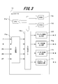
- FIG. 3 is a block diagram showing a hardware configuration example of the controller 11.
- Each output signal output from the accelerator opening sensor 7, the brake switch 8, the vehicle speed sensor 25, the battery voltage sensor 26, and the crank angle sensor 27 is input to the input circuit 11a of the controller 11.
- the input signal is not limited to these.
- the input signal of each sensor input to the input circuit 11a is sent to an input port (not shown) in the input / output port 11b.
- the value sent to the input port is stored in the RAM 11c and processed by the CPU 11e.
- the control program that describes the operation contents is written in advance in the ROM 11d.
- the CPU 11e realizes the functions of the search area processing unit 31, the traffic information acquisition unit 32, the route calculation unit 33, the optimum route output unit 34, and the power train command unit 35 shown in FIG. 4, which will be described later.
- a value indicating the operating amount of the control target (engine 17, generator 18, battery 12, motor 21, etc.) calculated according to the control program is stored in the RAM 11c and then stored in the output port (not shown) in the input / output port 11b. It is sent and sent to each device via each output unit.
- the output unit there are an engine control output unit 11f, a motor control output unit 11g, a battery control output unit 11h, and a generator control output unit 11i.
- the circuits of each of these output units are connected to ECU 2, MCU 5, BCU 4, and GCU 3. In FIG.
- a controller 11 is provided with a control device (ECU 2, MCU 5, BCU 4 and GCU 3) to be controlled separately, but the present invention is not limited to this form, and a functional unit corresponding to the control device of each device is provided. It may be provided in the controller 11.
- FIG. 4 is a block diagram showing an example of the internal configuration of the controller 11.
- the controller 11 includes a search area processing unit 31, a traffic information acquisition unit 32, a route calculation unit 33, an optimum route output unit 34, and a power train command unit 35.
- the function of the controller 11 is different depending on whether the vehicle 1 is a stopped vehicle or a moving vehicle.
- the vehicle side recording unit 36 is connected to the controller 11.
- the vehicle-side recording unit 36 is composed of, for example, a recording device such as a RAM 11c shown in FIG. 3, an HDD (Hard Disk Drive) (not shown), or an SSD (Solid State Drive).
- the vehicle-side communication unit 13 When the vehicle 1 is a stopped vehicle, the vehicle-side communication unit 13, the search area processing unit 31, the traffic information acquisition unit 32, the route calculation unit 33, and the vehicle-side recording unit 36 operate. Then, the controller (controller 11) is allocated from the route planning device (management server 40) through the vehicle side communication unit (vehicle side communication unit 13) when the route planning device (management server 40) determines that the vehicle is stopped. The calculation process is performed, and the calculation result is transmitted to the route planning device (management server 40).
- the vehicle-side communication unit can communicate with the route planning device (management server 40) connected to the network N.
- the identification ID of the currently connected network and the information on the current position of the vehicle 1 acquired from the navigation device 14 are transmitted to the management server 40.
- the management server 40 determines that the vehicle 1 is a stopped vehicle
- the vehicle-side communication unit 13 receives an instruction to start a route calculation by the stopped vehicle from the management server 40.
- This start instruction includes information such as the current location of the moving vehicle to be the target of the route calculation, the start point at which the moving vehicle starts moving, the end point at which the moving vehicle ends the movement, and the waypoint.
- the search area processing unit processes the search area designated by the route planning device (management server 40).
- the search area is an area defined so as not to increase the amount of calculation when searching the route too much, and the area in which the moving vehicle travels is limited by the search area. For example, a limited area such as a specific city, ward, or town is used as a search area. Then, the search area processing unit 31 reduces the search space by processing the search area by using, for example, ZDD (Zero-suppressed Binary Decision Diagram) shown in FIG. 10 described later.
- ZDD Zero-suppressed Binary Decision Diagram
- the traffic information acquisition unit acquires traffic information in the search area processed by the search area processing unit 31.
- the traffic information can be obtained from, for example, the navigation device 14.
- Traffic information includes, for example, map information including maps, intersections, traffic light installation locations, etc., traffic congestion information, information indicating the cost of electric power that can be charged to the battery 12 in a certain area and time zone, stores where a charger is installed. Information, and at least one or more of the information such as the availability information of the parking lot.
- the calculation unit performs calculation processing based on the processed search area and traffic information. By this arithmetic processing, a route through which a moving vehicle can travel efficiently is required. If there are multiple waypoints between a certain start point and end point, the moving vehicle cannot reach the end point at the fastest speed if the moving vehicle is caught in a traffic jam by selecting a route with a short distance on the map. Therefore, the route calculation unit 33 calculates the route in consideration of the traffic information, so that the moving vehicle can arrive at the end point as soon as possible while avoiding traffic congestion even if the route of the moving vehicle becomes long.
- the vehicle side recording unit 36 records the calculation result obtained by the route calculation unit 33 as the history calculated for the moving vehicle. As will be described later, the vehicle-side recording unit 36 also records the content of the command commanded to the power train of the moving vehicle as the history of the moving vehicle.
- the vehicle-side communication unit 13 transmits the calculation result obtained by the route calculation unit 33 to the management server 40.
- the calculation result according to the present embodiment includes, for example, a route recommended for a moving vehicle, a CO 2 emission amount emitted when the moving vehicle travels along the route, and the like.
- the vehicle side communication unit 13 When the vehicle 1 is a moving vehicle, the vehicle side communication unit 13, the optimum route output unit 34, the power train command unit 35, and the vehicle side recording unit 36 operate.
- the vehicle-side communication unit 13 receives the optimum route selected by the management server 40.
- the optimum route output unit 34 outputs the optimum route received by the vehicle-side communication unit 13 from the management server 40 to, for example, the navigation device 14.
- the display panel of the navigation device 14 displays the optimum route of the moving vehicle.
- the power train command unit 35 issues a command to the power train so that the vehicle 1 can travel according to the optimum route received by the vehicle side communication unit 13.
- the power train is a general term for devices related to the traveling of the vehicle 1, and includes, for example, an engine 17, a generator 18, a motor 21, a reduction gear 22, and the like. Then, the power train command unit 35 records the driving history including the command value for each part commanded to the power train in the vehicle side recording unit 36.
- the vehicle-side communication unit 13 transmits the driving history of the moving vehicle read from the vehicle-side recording unit 36 to the management server 40.
- the timing at which the vehicle-side communication unit 13 transmits the driving history may be real time or may be after the vehicle 1 has stopped.
- FIG. 5 is a block diagram showing an example of the internal configuration of the management server 40.
- the management server 40 includes a server-side communication unit 41, a position confirmation unit 42, an objective function determination unit 43, a vehicle determination unit 44, a calculation allocation determination unit 45, an optimum route determination unit 46, and a server-side recording unit 47.
- the device-side communication unit is a vehicle (vehicle) equipped with a motor (motor 21) used as a drive source and a battery (battery 12) capable of supplying electric power for operating the motor (motor 21). It is possible to communicate with a plurality of vehicles (vehicle 1) by connecting to 1) through a network (network N).
- the server-side communication unit 41 can communicate with each other between the position confirmation unit 42, the vehicle determination unit 44, the calculation allocation determination unit 45, and the optimum route determination unit 46.
- the position confirmation unit (position confirmation unit 42) is a waypoint through which the vehicle (vehicle 1) passes from the start point at which the vehicle (vehicle 1) starts moving to the end point at which the vehicle (vehicle 1) ends its movement. And confirm the position of the vehicle (vehicle 1). Therefore, the position confirmation unit 42 receives information indicating the current position of each vehicle 1 from the plurality of vehicles 1 through the server-side communication unit 41. For example, the position confirmation unit 42 receives the information indicating the current position of the stopped vehicle positioned by the navigation device 14 of the stopped vehicle, and receives the calculation result transmitted from the stopped vehicle. Further, the position confirmation unit 42 receives the information indicating the current position of the stopped vehicle positioned by the navigation device 14 of the moving vehicle, and receives the driving history transmitted from the moving vehicle.
- the objective function determination unit determines the objective function according to a preset purpose.
- the objective function is a function that satisfies one objective selected from a plurality of preset objectives or a plurality of objectives combined at a predetermined ratio.
- the objective function is a function used to determine the optimum route of a moving vehicle.
- the objective function determination unit determines the objective function based on the objective set through the objective setting screen (objective setting screen 60) shown in FIG. 8 to be described later.
- the purpose is to shorten the travel time of the mobile vehicle from the start point to the end point, reduce the energy consumed by the mobile vehicle, reduce the procurement cost of the energy consumed by the mobile vehicle, and the mobile vehicle.
- the energy includes at least one of thermal energy obtained by burning fossil fuel and electric energy.
- the optimum route of the moving vehicle changes depending on the purpose set in advance by the user, such as prioritizing the running cost, prioritizing the CO 2 emission amount when the moving vehicle moves, or how to allocate these combinations. ..
- the vehicle determination unit is moving or each vehicle (vehicle 1) is moving or based on the information collected from a plurality of vehicles (vehicle 1) through the device side communication unit (server side communication unit 41). Determine whether it is a moving vehicle that is scheduled to move or a stopped vehicle that is stopped. For example, the vehicle determination unit 44 determines whether the vehicle 1 is a stopped vehicle depending on whether or not the vehicle 1 has moved after a predetermined time has elapsed from the current position of each vehicle 1 confirmed by the position confirmation unit 42.
- the remaining amount of the battery (battery 12) is equal to or less than a predetermined value among the stopped vehicles equipped with the battery (battery 12).
- the vehicle determination unit refers to a stopped vehicle in which energy is not supplied to the battery (battery 12) from the power supply device (power supply device 30) and the vehicle is not scheduled to be dispatched.
- the movement of the stopped vehicle is instructed from the power supply device (power supply device 30) to a place where energy can be supplied to the battery (battery 12).
- the calculation allocation determination unit (calculation allocation determination unit 45) moves to a stopped vehicle capable of calculating an objective function by consuming the energy supplied from the energy storage unit (battery 12) to the drive source (motor 21).
- the allocation of the calculation process for planning the route of the moving vehicle is determined, and the controller (controller 11) of the stopped vehicle is made to calculate through the device side communication unit (server side communication unit 41).
- the calculation allocation determination unit (calculation allocation determination unit 45) includes the remaining amount of the battery (battery 12) mounted on the stopped vehicle, the power supply device (power supply device 30), and the battery (battery 12) mounted on the stopped vehicle.
- the allocation of arithmetic processing is determined based on the vehicle allocation plan that defines the supply and demand state of energy, the area including the waypoint where the mobile vehicle is dispatched, and the time zone when the mobile vehicle is dispatched.
- the calculation allocation determination unit 45 causes the vehicle 1 determined to be a stopped vehicle to perform calculation processing for searching the route of the moving vehicle.
- the calculation allocation determination unit 45 appropriately allocates calculation processing to be performed by the controller 11 mounted on each vehicle 1.
- the calculation allocation determination unit 45 transmits the allocated calculation processing to the stopped vehicle through the server-side communication unit 41.
- the route determination unit determines and determines the route of the moving vehicle based on the calculation results of the arithmetic processing collected from the plurality of stopped vehicles through the device side communication unit (server side communication unit 41). Notify the moving vehicle of the route.
- the route to be determined is, for example, the optimum route for a moving vehicle.
- the calculation result is received by the server-side communication unit 41 from each stopped vehicle. Further, the optimum route determination unit 46 records the determined optimum route in the server-side recording unit 47. Further, the optimum route determination unit 46 transmits the optimum route determined by the optimum route determination unit 46 to the mobile vehicle through the server-side communication unit 41.
- the optimum route determination unit 46 records the movement history or the driving history acquired from the moving vehicle through the server-side communication unit 41 in the server-side recording unit 47.
- the movement history is a history of moving vehicles that have moved along the optimum route.
- the driving history is a history of the steering wheel angle when the driver drives a moving vehicle, the depression state of the accelerator, and the like.
- the device-side recording unit (server-side recording unit 47) records the route determined by the route determination unit (optimal route determination unit 46). Then, the route determination unit (optimal route determination unit 46) is on the device side when the conditions for determining the current route are substantially the same as or substantially the same as the conditions when the route was determined in the past.
- the recording unit (server-side recording unit 47) notifies the moving vehicle of the route determined in the past.
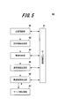
- FIG. 6 is a block diagram showing a hardware configuration example of the computer 50.
- the computer 50 is hardware used as a computer that can operate as a management server 40.
- the computer 50 includes a CPU (Central Processing Unit) 51, a ROM (Read Only Memory) 52, a RAM (Random Access Memory) 53, and a bus 54, which are connected to the bus 54, respectively. Further, the computer 50 includes a non-volatile storage 57 and a network interface 58.
- CPU Central Processing Unit
- ROM Read Only Memory
- RAM Random Access Memory
- the CPU 51 reads the program code of the software that realizes each function according to the present embodiment from the ROM 52, loads it into the RAM 53, and executes it. Variables and parameters generated during the arithmetic processing of the CPU 51 are temporarily written in the RAM 53, and these variables and parameters are appropriately read by the CPU 51.
- an MPU Micro Processing Unit
- the CPU 51 realizes the functions of the position confirmation unit 42, the objective function determination unit 43, the vehicle determination unit 44, the calculation allocation determination unit 45, and the optimum route determination unit 46 shown in FIG.
- the display device 55 is, for example, a liquid crystal display monitor, and outputs a screen (for example, the purpose setting screen 60 shown in FIG. 8 to be described later) for displaying the result of processing performed by the computer 50 to the operator.
- a keyboard, a mouse, or the like is used as the input device 56, and the operator can perform predetermined operation inputs and instructions. Further, the operator can set the purpose through the input device 56.
- the display device 55 and the input device 56 may not be provided depending on the configuration of the device.
- an information processing terminal such as a PC that can be connected to the management server 40 via the network N has a display device 55 and an input device 56, and a screen (for example, a purpose setting shown in FIG. 8 described later) is displayed on the display device 55.
- the screen 60) may be displayed and the user may set the purpose.
- the non-volatile storage 57 includes information such as HDD (Hard Disk Drive), SSD (Solid State Drive), flexible disk, optical disk, magneto-optical disk, CD-ROM, CD-R, magnetic tape, or non-volatile memory.
- a recording medium is used.
- the OS Operating System
- a program for operating the computer 50 is recorded.
- the ROM 52 and the non-volatile storage 57 permanently record programs, data, and the like necessary for the CPU 51 to operate, and are a computer-readable non-transient recording medium that stores the programs executed by the computer 50. It is used as an example.
- the server-side recording unit 47 shown in FIG. 5 is configured as a non-volatile storage 57.
- a NIC Network Interface Card
- various data can be transmitted and received between the devices via a LAN (Local Area Network) connected to the terminal of the NIC, a dedicated line, or the like.
- the server-side communication unit 41 operates the network interface 58 to send and receive various data to and from the vehicle 1.
- FIG. 7 is a diagram showing an example of a route search process performed in cooperation with the management server 40, the stopped vehicle, and the moving vehicle.
- This route search process shows an example of the route planning method according to the present embodiment.
- the illustration of the network N is omitted.
- the position confirmation unit 42 of the management server 40 confirms the delivery location and the vehicle position of each vehicle 1 based on the position information of the stopped vehicle and the moving vehicle received by the server-side communication unit 41 (S1).
- the objective function determination unit 43 determines the objective function according to the purpose of the route search (S2). In the present embodiment, the moving time of the vehicle 1 [min / km], the energy cost of moving the vehicle 1 (hereinafter abbreviated as “moving cost”) [ ⁇ / km], and the CO 2 emission of the moving vehicle 1 The purpose is to minimize the combined value of any one or more of the amounts [g / km]. Further, the objective function determining unit 43 weights each element when combining two or more elements from the moving time of the vehicle 1, the moving cost of the vehicle 1, and the CO 2 emission amount when the vehicle 1 moves. You can also decide.
- FIG. 8 is a diagram showing a display example of the purpose setting screen 60 of the moving time, moving cost, and CO 2 emission amount of the vehicle 1.
- the user can set the purpose in the route search of the moving vehicle through the purpose setting screen 60.
- the purpose setting screen 60 is displayed on the display device 55 of the management server 40 or an information processing terminal (not shown) connected to the management server 40.
- the purpose setting screen 60 includes a movement time setting unit 61, a movement cost setting unit 62, and a CO 2 emission amount setting unit 63.
- the movement time setting unit 61 includes a target bar 61a and a current value 61b.
- the target bar 61a represents the movement time of the moving vehicle set in the past.
- the current value 61b represents the average value of the travel times set for the plurality of vehicles 1.
- the movement cost setting unit 62 includes a target bar 62a and a current value 62b.
- the target bar 62a represents the movement cost of the moving vehicle set in the past.
- the current value 62b represents the average value of the moving costs set for the plurality of vehicles 1.
- the CO 2 emission amount setting unit 63 includes a target bar 63a and a current value 63b.
- the target bar 63a represents the CO 2 emissions of the mobile vehicle set in the past.
- the current value 63b represents the average value of the CO 2 emissions set in the plurality of vehicles 1.
- the movement cost setting unit 62 for example, some value that increases clockwise is displayed.
- the user can appropriately change the current values 61b, 62b, 63b while observing the value displayed on the meter portion.
- an importance display unit 64 indicating the importance of the route search is provided.
- the importance display unit 64 is set so that the ratio of the three types of importance is 100% in total.
- the user changes the current value 61b of the travel time setting unit 61, the current value 62b of the travel cost setting unit 62, and the current value 63b of the CO 2 emission amount setting unit 63, so that the importance displayed on the importance display unit 64 is important. You can change the percentage of degrees.
- the importance display unit 64 displays the travel time, travel cost, and CO 2 emission amount. In either case, the user can arbitrarily move the current values 61b, 62b, 63b to set the value. Then, in the objective function determination unit 43 shown in FIG. 5, the objective function is determined according to the ratio of the importance set on the objective setting screen 60.
- the moving cost per kwh of the electric power used for charging and the CO 2 emission amount vary depending on the region, the time zone, and the charging speed.
- the moving cost per kWh and the CO 2 emission amount are high, but the battery 12 can be quickly charged to shorten the time until the charging is completed.
- the moving cost per kWh and the CO 2 emission amount are low, but the battery 12 cannot be charged quickly, so it takes a long time to complete charging. Become.
- the battery 12 cannot be charged at night or on a cloudy day. Therefore, in the search process for the optimum route according to the present embodiment, calculations are performed in consideration of the value and price of these electric powers.
- the purpose of minimizing which element is different for each user For example, on a day when a lot of luggage is loaded on a moving vehicle, it is necessary to determine a route on which the moving vehicle can move in the shortest time. On the other hand, on days when the amount of luggage is small, it is easy to prioritize minimizing travel costs over time. Further, users who place importance on environmental friendliness such as RE100 (Renewable Energy 100%) often preferentially select a route that minimizes CO 2 emissions. Therefore, the user can freely select the purpose of the route search according to various usage scenes.
- RE100 Renewable Energy 100%
- the vehicle determination unit 44 determines a stopped vehicle capable of performing arithmetic processing based on the position information of the plurality of vehicles 1 (S3).
- the wireless network a large number of cells that define the communication range are provided, and the vehicle 1 in the cells can communicate in the same cell. Therefore, if the vehicle 1 is a stopped vehicle, the network (cell) to which the controller 11 of the vehicle 1 is connected does not change. However, if the vehicle 1 is a moving vehicle, the network (cell) to which the controller 11 of the vehicle 1 is connected is switched according to the movement of the vehicle 1.
- the vehicle determination unit determines that the vehicle 1 connected to the network that has not changed for a certain period of time or more is a stopped vehicle.
- the vehicle determination unit 44 may send a survival confirmation signal to the vehicle 1 and determine whether or not the vehicle 1 is a stopped vehicle based on the response signal received from the vehicle 1.
- the detailed processing flow for determining the stopped vehicle in step S3 will be described later in FIG.
- the controllers 11 of the plurality of stopped vehicles perform parallel arithmetic of the arithmetic processing assigned from the management server 40, respectively, and search the route of the moving vehicle or the vehicle scheduled to be moved. Therefore, the calculation allocation determination unit 45 determines the allocation of the route calculation to the stopped vehicle (S4). Specifically, the calculation processing assigned by the calculation allocation determination unit 45 according to the search area where the route is scheduled to be set, the remaining battery level of the vehicle 1 having the controller 11 that executes the calculation processing, and the future movement plan. Determine the load. The calculation allocation determination unit 45 notifies the stopped vehicle of the content of the calculation process through the server-side communication unit 41 according to the determined allocation.
- the search area processing unit 31 of the stopped vehicle performs processing to reduce the search area (S11).
- ZDD is assumed as the route search method, but other methods may be used.
- the method using ZDD is a method of mapping the network diagram of the movement route to the search tree, and it is possible to reduce the search space by pruning the branches early in consideration of the constraints in the conversion process to the search tree. Is.
- the traffic information acquisition unit 32 acquires traffic information in the search area from the navigation device 14 (S12). Then, the route calculation unit 33 calculates the movement route of the moving vehicle in the search area (S13). The calculation result including the movement route calculated by the route calculation unit 33 is transmitted to the management server 40 through the vehicle side communication unit 13. Further, the route calculation unit 33 records the calculation result including the movement route and the driving history of the stopped vehicle in the vehicle side recording unit 36 of the stopped vehicle (S14).
- the optimum route determination unit 46 determines the optimum route of the moving vehicle by collecting the plurality of calculation results received from the plurality of stopped vehicles (S5). Then, the optimum route determination unit 46 transmits the optimum route to the moving vehicle through the server-side communication unit 41.
- the optimum route determination unit 46 records the history of determining the route search in the server side recording unit 47 as the movement route history.
- the movement route history recorded in the server-side recording unit 47 is shared so as to be available in the process of calculating the movement route of another moving vehicle.
- the optimum route determination unit 46 is the server-side recording unit 47 when the conditions for determining the current route are substantially the same as or substantially the same as the conditions when the route was determined in the past. Notify other moving vehicles of the route read from.
- the calculation allocation determination unit 45 determines that the calculation process for the moving vehicle that is moving or is scheduled to move cannot be performed because the number of stopped vehicles determined in the process of step S3 is small, the server side.
- the route search is performed based on the movement route history recorded in the recording unit 47.
- the vehicle-side communication unit 13 of the moving vehicle outputs the optimum route received from the management server 40 to the navigation device 14, thereby displaying the optimum route on the display screen of the navigation device 14 (S21).
- the vehicle side communication unit 13 outputs the optimum route to the power train command unit 35.
- the power train command unit 35 outputs a command to the power train according to the optimum path (S22).
- the power train is controlled according to the schedule of the optimum route output by the vehicle-side communication unit 13.
- Powertrain control is, for example, determining a target control amount of the remaining battery level (SOC: StateOfCharge) of the battery 12, engine operation control of a hybrid vehicle, and engine operation conditions (rotation speed, torque). ..
- SOC StateOfCharge
- Engine operation control of a hybrid vehicle and engine operation conditions (rotation speed, torque). ..
- the powertrain of the moving vehicle is driven according to a command, and the moving vehicle moves along the optimum route.
- the power train command unit 35 records the driving history of the moving vehicle in the vehicle side recording unit 36 (S23).
- the driving history includes at least information including a route in which the moving vehicle has moved along the optimum route and a command history commanded by the power train command unit 35. Further, the driving history recorded in the vehicle-side recording unit 36 is transmitted to the management server 40 through the vehicle-side communication unit 13.
- the server-side communication unit 41 records the driving history received from the moving vehicle in the server-side recording unit 47.
- the server-side recording unit 47 records the movement route history and the driving history determined for each of a plurality of moving vehicles. For example, when the stopped vehicle is made to calculate the optimum route in the future, the stopped vehicle is calculated. Is not performed, and the optimum route read from the server-side recording unit 47 is transmitted to the moving vehicle. In this way, the optimum route and the history of the movement route actually moved by the moving vehicle can be shared.
- FIG. 9 is a flowchart showing an example of a process in which the vehicle determination unit 44 determines a stopped vehicle. In this process, an electric vehicle will be described.
- the remaining battery level (SOC) is an index represented by ⁇ remaining capacity (Ah) / fully charged capacity (Ah) ⁇ ⁇ 100.
- SOCmax is, for example, a value of about 90% of the total capacity of the battery 12.
- SOCmax is, for example, a value of about 90% of the total capacity of the battery 12.
- the minimum SOC value (SOCmin) is, for example, a value of about 10% of the total capacity of the battery 12. Since the SOC minimum value (SOCmin) is not zero, the vehicle 1 can travel a short distance even if the remaining battery level becomes the SOC minimum value (SOCmin) or less.
- the vehicle determination unit 44 determines whether or not the remaining battery level (SOC) of the vehicle 1 is larger than the minimum SOC value (SOCmin) (S31). If the SOC is SOC min or less (NO in S31), the vehicle determination unit 44 determines whether or not the vehicle 1 is being charged (S32).
- the vehicle determination unit 44 requests the vehicle 1 to be charged (S33), and proceeds to step S4 in FIG. Since the vehicle 1 that has received the charge request is preferentially charged, the controller 11 of the vehicle 1 is not preferentially used.
- step S34 the controller 11 of the vehicle 1 is preferentially used. Since this vehicle 1 has an extremely low SOC, it is difficult to use it as a mobile vehicle until the SOC increases. However, if the vehicle 1 is being charged, the controller 11 mounted on the vehicle 1 can be utilized. Therefore, the vehicle determination unit 44 determines that the controller 11 of the charging vehicle 1 can be used preferentially over the route search by the other vehicle 1. After step S34, the process proceeds to step S4 of FIG.
- step S31 when the vehicle determination unit 44 determines that the SOC is larger than the SOC min (YES in S31), it determines whether the remaining battery level (SOC) is larger than the SOC maximum value (SOCmax). (S35). When the SOC is equal to or less than the SOCmax (NO in S35), the vehicle determination unit 44 determines whether or not the vehicle 1 is being charged (S36).
- the vehicle determination unit 44 determines whether or not the vehicle 1 is scheduled to be dispatched (S37). The vehicle determination unit 44 can determine whether or not there is a target to be delivered near the vehicle 1, the positional relationship between the vehicle 1 and another vehicle 1, the current SOC value, and the power train configuration.
- the vehicle determination unit 44 selects whether to preferentially utilize the controller 11 of the vehicle 1 in the route search or to request charging (S38).
- the vehicle determination unit 44 requests charging, the vehicle 1 gives an instruction to move to the charging area. Further, after the vehicle 1 has moved to the charging area, the vehicle determination unit 44 makes a charging request to the vehicle 1. After step S38, the process proceeds to step S4 of FIG.
- the vehicle determination unit 44 determines whether or not the vehicle 1 can travel with the current SOC remaining amount based on the distance and route to the target to which the luggage is delivered. (S39).
- the fact that the vehicle 1 can travel means, for example, that the vehicle 1 can travel in the delivery area with a margin. When the vehicle can travel only a few kilometers, the vehicle determination unit 44 determines that the vehicle 1 cannot travel.
- the vehicle determination unit 44 determines that the vehicle 1 cannot travel because the SOC of the vehicle 1 is small (NO in S39), the vehicle 1 is moved to the charging area (S40), or the vehicle 1 in the charging area is located. A charging request is sent to the vehicle 1 to charge the vehicle 1. This process is a control in which the vehicle determination unit 44 charges the vehicle 1 to increase the SOC of the vehicle 1.
- step S39 When the vehicle determination unit 44 determines in step S39 that the vehicle 1 can travel (YES in S39), the vehicle determination unit 44 determines that the vehicle 1 has priority on vehicle allocation (S41). The vehicle 1 determined by the vehicle determination unit 44 to give priority to vehicle allocation is treated as a moving vehicle. After step S41, the process proceeds to step S4 of FIG.
- step S36 the process when the vehicle determination unit 44 determines that charging is in progress (YES in S36) will be described.
- the vehicle determination unit 44 determines whether or not the vehicle 1 is scheduled to be dispatched (S42). If there is no plan to dispatch the vehicle 1 (NO in S42), the vehicle determination unit 44 determines that the controller 11 of the vehicle 1 can be used for route search with priority over the controller 11 of the other vehicle 1 (NO). S43). After step S43, the process proceeds to step S4 of FIG.
- the vehicle determination unit 44 determines whether or not the vehicle 1 can travel with the current SOC remaining amount based on the distance and route to the target to which the vehicle 1 delivers the package. Is determined (S44). When the vehicle determination unit 44 determines that the SOC of the vehicle 1 is small and the mileage of the vehicle 1 is short and the vehicle 1 cannot travel (NO in S44), the controller 11 of the vehicle 1 is used by another vehicle. It is determined that 1 can be used preferentially over the route search (S45). After step S45, the process proceeds to step S4 of FIG.
- step S44 determines in step S44 that the vehicle 1 can travel (YES in S44)
- the vehicle determination unit 44 determines that the vehicle 1 has priority on vehicle allocation (S49). After step S49, the process proceeds to step S4 of FIG.
- step S35 when the vehicle determination unit 44 determines that the remaining battery level (SOC) is larger than the maximum SOC value (SOCmax) (YES in S35), the vehicle determination unit 44 indicates that the vehicle 1 is not charging. Judgment (S46).
- the vehicle determination unit 44 determines whether or not the vehicle 1 is scheduled to be dispatched (S47). If there is no plan to dispatch the vehicle 1 (NO in S47), the vehicle determination unit 44 determines that the controller 11 possessed by the vehicle 1 can be used for route search in preference to the controller 11 of the other vehicle 1 (NO). S51). After step S51, the process proceeds to step S4 of FIG.
- the vehicle determination unit 44 determines whether or not the vehicle 1 can travel with the current SOC remaining amount based on the distance to the delivery target and the route (YES in S47). S48). When the vehicle determination unit 44 determines that the vehicle 1 can travel (YES in S48 or YES in S44), the vehicle 1 determines that the vehicle allocation is prioritized (S49). After step S49, the process proceeds to step S4 of FIG.
- step S50 the controller 11 of the vehicle 1 is preferentially used. That is, the controller 11 of this vehicle 1 is utilized for route search of another vehicle 1. After step S50, the process proceeds to step S4 of FIG.
- the stopped vehicles that can utilize the controller 11 are narrowed down.
- the route calculation allocation process performed by the calculation allocation determination unit 45 in step S4 of FIG. 7 determines the stopped vehicle for which the route search is performed with priority from the narrowed down stopped vehicles.
- the calculation allocation determination unit 45 uses the vehicle 1 which is unlikely to be dispatched in steps S34, S38, S43, S45, S50, and S51 shown in the shaded area of FIG. Select with priority. At this time, the calculation allocation determination unit 45 considers at least one or more of the remaining battery level (SOC), the positional relationship of the plurality of vehicles 1 to be dispatched, and the delivery destination area.
- SOC remaining battery level
- the stopped vehicle targeted in step S34 has a low SOC and is difficult to move, so there is a high possibility that it will be selected with the highest priority.
- the stopped vehicle targeted in steps S50 and S51 has a high SOC, there is a high possibility that it will be selected as a mobile vehicle with the highest priority at the next vehicle allocation. Therefore, a stop vehicle having a high SOC is assigned a calculation having a lower load than other stopped vehicles in order not to affect the vehicle allocation.
- the allocation of arithmetic processing is relatively determined from the positional relationship of each stopped vehicle, the SOC, and the configuration of the power train.
- step S11 of FIG. 7 processing is performed by the search area processing unit 31. That is, in FIG. 7, the controller 11 (search area processing unit 31) of the vehicle 1 determined to be a stopped vehicle by the vehicle determination unit 44 of the management server 40 performs a process of processing the search area.
- FIG. 10 is an explanatory diagram showing an example of processing by the search area processing unit 31.
- the search area processing unit processes the search area by ZDD (zero suppression type binary determination graph) using preset constraint conditions.
- ZDD is, for example, the following non-patent documents (“Graph enumeration indexing technique using BDD / ZDD”, [online], [Search on May 31, 1991], Internet ⁇ http://www.orsj .or.jp/archive2/or57-11/or57_11_597.pdf>) is the technology shown.
- the route search from the start point s to the end point t is performed.
- the network diagram shown on the left side of FIG. 10 can be converted into a tree-structured search tree shown on the right side of FIG.
- the search space can be reduced by considering the constraints.
- the constraint condition is, for example, to search the entire route connecting the start point and the end point and the Euler route with a single stroke.
- arithmetic processing for planning the route of the moving vehicle is assigned to the controller 11 of the stopped vehicle selected by the management server 40.
- the management server 40 preferentially allocates the arithmetic processing for searching the route of the moving vehicle to the vehicle 1 (stopped vehicle) having a low probability of moving most recently, and causes the moving vehicle to search the route. Since the controllers 11 of a plurality of stopped vehicles execute arithmetic processing in parallel, it is not necessary to increase the arithmetic load of the controllers 11 of the moving vehicle. By utilizing the controller 11 of the stopped vehicle for the route search of the moving vehicle in this way, the operating rate of the controller 11 mounted on the stopped vehicle can be improved.
- the overall processing capacity of the stopped vehicles is higher than the processing capacity of one controller 11 or the management server 40. Therefore, it is not necessary to excessively increase the processing capacity of the controller 11 and the management server 40, and the equipment cost can be suppressed. As a result, it is possible to shorten the equipment collection period of the delivery company or the sharing company that uses the movement route search system 100.
- stopped vehicles often do not have a driver. Therefore, even if the controller 11 of the stopped vehicle is utilized, the driver is not affected.
- Various purposes can be set as the purpose in the route search of the moving vehicle. If the travel time is to be minimized, the shortest route is searched, and if the travel cost is to be suppressed, for example, via a charging area that can store the electric energy obtained by inexpensive solar power generation. The route is searched. In addition, if CO 2 emissions are to be suppressed, a route that does not require frequent acceleration and deceleration is searched for. Since a plurality of these purposes can be combined and weighted for each purpose, it is possible to search for a route for the purpose according to the user's request.
- the calculation amount of the process allocated to the plurality of stopped vehicles by the calculation allocation determination unit 45 may be different for each stopped vehicle. For example, in the case of a stopped vehicle, when a person is in the vehicle and the air conditioner is operating, the calculation amount of the processing allocated to the stopped vehicle may be suppressed.
- the route search process according to the present embodiment may be performed by batch processing before the moving vehicle departs from the starting point, or may be performed by real-time processing while the moving vehicle is moving.
- the management server 40 can update the optimum movement route according to the traffic information and the weather information that change from moment to moment by real-time processing, and provide the moving vehicle with the route suitable for the purpose.
- the vehicle 1 may have only a stopped vehicle configuration or a moving vehicle configuration.
- the vehicle 1 includes only the vehicle side communication unit 13, the search area processing unit 31, the traffic information acquisition unit 32, the route calculation unit 33, and the vehicle side recording unit 36 shown in FIG. ..
- the vehicle 1 includes only the vehicle side communication unit 13, the optimum route output unit 34, the power train command unit 35, and the vehicle side recording unit 36 shown in FIG.
- the vehicle-side communication unit 13, the search area processing unit 31, the traffic information acquisition unit 32, the route calculation unit 33, and the vehicle-side recording unit 36 which are configured as a stopped vehicle, process information such as a PC that can be connected to the management server 40. It may be provided in the terminal.
- the vehicle 1 selected as the stopped vehicle may be a vehicle having the controller 11. Therefore, a parallel hybrid vehicle, a liquefied natural gas vehicle, a hydrogen vehicle, a gasoline vehicle, or the like may be selected as a stopped vehicle.
- the energy supplied to the drive source is thermal energy obtained by burning fossil fuel and electric energy.
- the energy supplied to the drive source is the thermal energy obtained by burning the liquefied natural gas.
- the energy supplied to the drive source is the thermal energy obtained by burning hydrogen.
- the energy supplied to the drive source is the heat energy obtained by burning gasoline.
- the present invention is not limited to the above-described embodiment, and it goes without saying that various other application examples and modifications can be taken as long as the gist of the present invention described in the claims is not deviated.
- the above-described embodiment describes the configuration of the system in detail and concretely in order to explain the present invention in an easy-to-understand manner, and is not necessarily limited to the one including all the described configurations.
- the control lines and information lines indicate those that are considered necessary for explanation, and do not necessarily indicate all the control lines and information lines in the product. In practice, it can be considered that almost all configurations are interconnected.
Landscapes
- Engineering & Computer Science (AREA)
- Radar, Positioning & Navigation (AREA)
- Remote Sensing (AREA)
- Physics & Mathematics (AREA)
- General Physics & Mathematics (AREA)
- Automation & Control Theory (AREA)
- Mathematical Physics (AREA)
- Signal Processing (AREA)
- Computer Networks & Wireless Communication (AREA)
- Life Sciences & Earth Sciences (AREA)
- Sustainable Development (AREA)
- Sustainable Energy (AREA)
- Power Engineering (AREA)
- Transportation (AREA)
- Mechanical Engineering (AREA)
- Electric Propulsion And Braking For Vehicles (AREA)
- Navigation (AREA)
- Traffic Control Systems (AREA)
Abstract
La présente invention concerne un serveur de gestion comprenant : une unité de confirmation de position qui confirme un point d'accès d'un véhicule et la position du véhicule ; une unité de détermination de fonction objective qui détermine une fonction objective ; une unité d'évaluation de véhicule qui évalue pour chaque véhicule parmi une pluralité de véhicules, si le véhicule est un véhicule en mouvement qui est en train de se déplacer ou est programmé pour se déplacer ou un véhicule arrêté qui est actuellement arrêté, sur la base d'informations collectées à partir de la pluralité de véhicules ; et une unité de détermination d'attribution de calcul qui détermine qu'un processus de calcul pour planifier un itinéraire pour un véhicule en mouvement se déplaçant en consommant de l'énergie fournie à une source de conduite à partir d'une unité de stockage d'énergie doit être attribué à un véhicule arrêté capable de calculer la fonction objective, et qui, par l'intermédiaire d'une unité de communication côté serveur, dirige un dispositif de commande du véhicule arrêté pour effectuer le calcul.
Priority Applications (3)
| Application Number | Priority Date | Filing Date | Title |
|---|---|---|---|
| EP20823216.5A EP3985638A4 (fr) | 2019-06-12 | 2020-03-10 | Dispositif de planification d'itinéraire, procédé de planification d'itinéraire, et système de planification d'itinéraire |
| CN202080036384.6A CN113841189B (zh) | 2019-06-12 | 2020-03-10 | 路径规划装置、路径规划方法以及路径规划系统 |
| US17/595,276 US20220252402A1 (en) | 2019-06-12 | 2020-03-10 | Route Planning Device, Route Planning Method, and Route Planning System |
Applications Claiming Priority (2)
| Application Number | Priority Date | Filing Date | Title |
|---|---|---|---|
| JP2019109255A JP7265423B2 (ja) | 2019-06-12 | 2019-06-12 | 経路計画装置、経路計画方法及び経路計画システム |
| JP2019-109255 | 2019-06-12 |
Publications (1)
| Publication Number | Publication Date |
|---|---|
| WO2020250512A1 true WO2020250512A1 (fr) | 2020-12-17 |
Family
ID=73742200
Family Applications (1)
| Application Number | Title | Priority Date | Filing Date |
|---|---|---|---|
| PCT/JP2020/010217 Ceased WO2020250512A1 (fr) | 2019-06-12 | 2020-03-10 | Dispositif de planification d'itinéraire, procédé de planification d'itinéraire, et système de planification d'itinéraire |
Country Status (5)
| Country | Link |
|---|---|
| US (1) | US20220252402A1 (fr) |
| EP (1) | EP3985638A4 (fr) |
| JP (1) | JP7265423B2 (fr) |
| CN (1) | CN113841189B (fr) |
| WO (1) | WO2020250512A1 (fr) |
Families Citing this family (7)
| Publication number | Priority date | Publication date | Assignee | Title |
|---|---|---|---|---|
| US11068832B1 (en) * | 2018-08-31 | 2021-07-20 | VuTrans Solutions LLC | System and method for identifying freight capacity |
| JP6762457B1 (ja) * | 2020-01-24 | 2020-09-30 | 三菱電機株式会社 | 制御装置、移動体、管理サーバ、基地局、通信システム及び通信方法 |
| JP7609039B2 (ja) * | 2021-11-02 | 2025-01-07 | トヨタ自動車株式会社 | 情報処理装置、システム、方法、及びプログラム |
| JP7544084B2 (ja) * | 2022-02-09 | 2024-09-03 | トヨタ自動車株式会社 | 車両 |
| JP7582237B2 (ja) * | 2022-03-17 | 2024-11-13 | トヨタ自動車株式会社 | 車両の運転支援システム |
| JP2024004676A (ja) * | 2022-06-29 | 2024-01-17 | 日産自動車株式会社 | 配車管理装置及び配車管理方法 |
| WO2025191845A1 (fr) * | 2024-03-15 | 2025-09-18 | Ntt株式会社 | Dispositif et programme |
Citations (7)
| Publication number | Priority date | Publication date | Assignee | Title |
|---|---|---|---|---|
| JPH0553500A (ja) * | 1991-08-26 | 1993-03-05 | Sumitomo Electric Ind Ltd | 車両誘導表示装置 |
| JPH05165408A (ja) * | 1991-12-18 | 1993-07-02 | Honda Motor Co Ltd | 車両走行案内装置 |
| JP2002318126A (ja) * | 2001-04-20 | 2002-10-31 | Aisin Aw Co Ltd | 車両用ナビゲーション装置及びプログラム |
| JP2004354086A (ja) * | 2003-05-27 | 2004-12-16 | Aisin Aw Co Ltd | ナビゲーションシステム |
| JP2007087273A (ja) * | 2005-09-26 | 2007-04-05 | Toyota Infotechnology Center Co Ltd | 分散処理システム及び車載端末 |
| JP2013120526A (ja) * | 2011-12-08 | 2013-06-17 | Toyota Central R&D Labs Inc | 車両分散処理システム及び車両分散処理方法 |
| JP2018028554A (ja) | 2013-10-31 | 2018-02-22 | 三菱重工業株式会社 | 車載器および電気自動車 |
Family Cites Families (35)
| Publication number | Priority date | Publication date | Assignee | Title |
|---|---|---|---|---|
| US6453298B2 (en) * | 1998-07-10 | 2002-09-17 | Honda Giken Kogyo Kabushiki Kaisha | Method of operating a vehicle redistribution system based upon predicted ride demands |
| JP4804059B2 (ja) * | 2005-07-28 | 2011-10-26 | 株式会社トヨタIt開発センター | 車載端末 |
| JP4375431B2 (ja) * | 2007-04-24 | 2009-12-02 | トヨタ自動車株式会社 | エネルギー補給量制御システム |
| DE102008046517A1 (de) * | 2008-09-10 | 2010-03-25 | Continental Automotive Gmbh | Verfahren zum Betrieb eines Fahrerinformationssystems und Fahrerinformationssystem |
| AU2010324651B2 (en) * | 2009-11-24 | 2015-10-22 | Telogis, Inc. | Vehicle route selection based on energy usage |
| US8793067B2 (en) * | 2009-12-28 | 2014-07-29 | Honda Motor Co., Ltd. | Route searching device |
| CN102116637A (zh) * | 2009-12-31 | 2011-07-06 | 上海博泰悦臻电子设备制造有限公司 | 基于车载设备服务平台的智能数据中心 |
| JP5607427B2 (ja) * | 2010-05-31 | 2014-10-15 | 株式会社モーション | 充電配車管理サーバ及び充電配車管理システム |
| US8583367B2 (en) * | 2011-01-07 | 2013-11-12 | Honda Motor Co., Ltd. | System and method for displaying a route based on a vehicle state |
| DE102011011213A1 (de) * | 2011-02-14 | 2012-08-16 | Deutsches Zentrum für Luft- und Raumfahrt e.V. | Automatische Unterstützung der Routenplanung |
| WO2013132593A1 (fr) * | 2012-03-06 | 2013-09-12 | トヨタ自動車 株式会社 | Dispositif et procédé de traitement d'informations de déplacement et système d'aide à la conduite |
| WO2013140586A1 (fr) * | 2012-03-22 | 2013-09-26 | トヨタ自動車株式会社 | Dispositif et système de commande de la circulation |
| JP6081902B2 (ja) * | 2013-10-31 | 2017-02-15 | 三菱重工業株式会社 | 走行経路案内装置、走行経路案内システム、走行経路案内方法およびプログラム |
| US20190279440A1 (en) * | 2014-09-23 | 2019-09-12 | Autoconnect Holdings Llc | Fleetwide vehicle telematics systems and methods |
| US9744870B2 (en) * | 2014-11-11 | 2017-08-29 | Empire Technology Development Llc | Wirelessly charging vehicles moving in vehicle convoy |
| JP6180458B2 (ja) * | 2015-04-17 | 2017-08-16 | 三菱電機株式会社 | 車両用エネルギーマネジメント装置 |
| US9970780B2 (en) * | 2015-11-19 | 2018-05-15 | GM Global Technology Operations LLC | Method and apparatus for fuel consumption prediction and cost estimation via crowd sensing in vehicle navigation system |
| DE112017001267B4 (de) * | 2016-03-11 | 2024-05-02 | Panasonic Automotive Systems Co., Ltd. | Automatikfahrzeug-Dispatchingsystem und Servervorrichtung |
| KR101897339B1 (ko) * | 2016-09-06 | 2018-09-11 | 현대자동차주식회사 | 전기 자동차의 주행가능거리 예측방법 및 그 시스템 |
| JP6520902B2 (ja) * | 2016-12-14 | 2019-05-29 | トヨタ自動車株式会社 | コネクティッド車両 |
| WO2018160724A1 (fr) * | 2017-02-28 | 2018-09-07 | Wayfarer, Inc. | Système de transport |
| US10123181B1 (en) * | 2017-05-03 | 2018-11-06 | Honeywell International Inc. | Systems and methods for collaborative vehicle mission operations |
| JP2019036017A (ja) * | 2017-08-10 | 2019-03-07 | 住友電気工業株式会社 | 制御装置、制御方法、およびコンピュータプログラム |
| US20190107406A1 (en) * | 2017-10-09 | 2019-04-11 | Nio Usa, Inc. | Systems and methods for trip planning under uncertainty |
| US10718630B2 (en) * | 2017-12-08 | 2020-07-21 | Ford Global Technologies, Llc | Electric vehicle cloud-based optimal charge route estimation |
| US10467581B2 (en) * | 2018-01-19 | 2019-11-05 | Udelv Inc. | Delivery management system |
| JP6421403B1 (ja) * | 2018-03-29 | 2018-11-14 | 国立大学法人 長崎大学 | 車載計算装置、車両およびシステム |
| US11181929B2 (en) * | 2018-07-31 | 2021-11-23 | Honda Motor Co., Ltd. | System and method for shared autonomy through cooperative sensing |
| US11163317B2 (en) * | 2018-07-31 | 2021-11-02 | Honda Motor Co., Ltd. | System and method for shared autonomy through cooperative sensing |
| JP2020086945A (ja) * | 2018-11-26 | 2020-06-04 | トヨタ自動車株式会社 | 配車管理装置、配車管理方法及び配車管理用コンピュータプログラム |
| WO2020133450A1 (fr) * | 2018-12-29 | 2020-07-02 | 驭势科技(北京)有限公司 | Système et procédé de partage de puissance de calcul au moyen d'un réseautage dynamique destinés à un dispositif mobile |
| US20200242929A1 (en) * | 2019-01-25 | 2020-07-30 | Honda Motor Co., Ltd. | Systems and methods for a transportation network |
| JP7131441B2 (ja) * | 2019-03-08 | 2022-09-06 | マツダ株式会社 | 自動車用演算システム |
| JP7251535B2 (ja) * | 2020-09-11 | 2023-04-04 | トヨタ自動車株式会社 | 配車システム、配車サーバ、及び配車方法 |
| JP2022061580A (ja) * | 2020-10-07 | 2022-04-19 | トヨタ自動車株式会社 | 情報処理装置、情報処理方法、およびプログラム |
-
2019
- 2019-06-12 JP JP2019109255A patent/JP7265423B2/ja active Active
-
2020
- 2020-03-10 EP EP20823216.5A patent/EP3985638A4/fr active Pending
- 2020-03-10 CN CN202080036384.6A patent/CN113841189B/zh active Active
- 2020-03-10 US US17/595,276 patent/US20220252402A1/en not_active Abandoned
- 2020-03-10 WO PCT/JP2020/010217 patent/WO2020250512A1/fr not_active Ceased
Patent Citations (7)
| Publication number | Priority date | Publication date | Assignee | Title |
|---|---|---|---|---|
| JPH0553500A (ja) * | 1991-08-26 | 1993-03-05 | Sumitomo Electric Ind Ltd | 車両誘導表示装置 |
| JPH05165408A (ja) * | 1991-12-18 | 1993-07-02 | Honda Motor Co Ltd | 車両走行案内装置 |
| JP2002318126A (ja) * | 2001-04-20 | 2002-10-31 | Aisin Aw Co Ltd | 車両用ナビゲーション装置及びプログラム |
| JP2004354086A (ja) * | 2003-05-27 | 2004-12-16 | Aisin Aw Co Ltd | ナビゲーションシステム |
| JP2007087273A (ja) * | 2005-09-26 | 2007-04-05 | Toyota Infotechnology Center Co Ltd | 分散処理システム及び車載端末 |
| JP2013120526A (ja) * | 2011-12-08 | 2013-06-17 | Toyota Central R&D Labs Inc | 車両分散処理システム及び車両分散処理方法 |
| JP2018028554A (ja) | 2013-10-31 | 2018-02-22 | 三菱重工業株式会社 | 車載器および電気自動車 |
Non-Patent Citations (1)
| Title |
|---|
| See also references of EP3985638A4 |
Also Published As
| Publication number | Publication date |
|---|---|
| JP7265423B2 (ja) | 2023-04-26 |
| EP3985638A1 (fr) | 2022-04-20 |
| EP3985638A4 (fr) | 2023-07-19 |
| CN113841189B (zh) | 2023-07-28 |
| US20220252402A1 (en) | 2022-08-11 |
| CN113841189A (zh) | 2021-12-24 |
| JP2020201796A (ja) | 2020-12-17 |
Similar Documents
| Publication | Publication Date | Title |
|---|---|---|
| JP7265423B2 (ja) | 経路計画装置、経路計画方法及び経路計画システム | |
| US20250206288A1 (en) | Method and system for controlling a powertrain in a hybrid vehicle | |
| US12447850B2 (en) | Dispatch-based charging for electric vehicle fleet | |
| US11443563B2 (en) | Driving range based on past and future data | |
| US10776168B2 (en) | Vehicle and computing system | |
| US11351981B2 (en) | Vehicle control system, vehicle control method, and storage medium | |
| KR102629082B1 (ko) | 차량 및 그 제어 방법 | |
| JP7540381B2 (ja) | 走行制御装置、方法、及びプログラム | |
| US20130268150A1 (en) | Predictive powertrain control using powertrain history and gps data | |
| JP2019131112A (ja) | 車両制御システム、車両制御方法、およびプログラム | |
| US11834032B2 (en) | Vehicle control device and vehicle control method | |
| JP3994966B2 (ja) | 走行パターン推定装置 | |
| JP4023445B2 (ja) | ハイブリッド車両の制御装置 | |
| JP7643219B2 (ja) | 情報処理装置、及び、情報処理方法 | |
| JP2023017381A (ja) | 経路決定装置および配車システム | |
| JP2024080838A (ja) | 情報処理装置、情報処理方法及びプログラム | |
| US12241751B2 (en) | Information providing apparatus | |
| JP2023072925A (ja) | 車両 |
Legal Events
| Date | Code | Title | Description |
|---|---|---|---|
| 121 | Ep: the epo has been informed by wipo that ep was designated in this application |
Ref document number: 20823216 Country of ref document: EP Kind code of ref document: A1 |
|
| NENP | Non-entry into the national phase |
Ref country code: DE |
|
| ENP | Entry into the national phase |
Ref document number: 2020823216 Country of ref document: EP Effective date: 20220112 |