WO2020250703A1 - Dispositif connecteur - Google Patents
Dispositif connecteur Download PDFInfo
- Publication number
- WO2020250703A1 WO2020250703A1 PCT/JP2020/021179 JP2020021179W WO2020250703A1 WO 2020250703 A1 WO2020250703 A1 WO 2020250703A1 JP 2020021179 W JP2020021179 W JP 2020021179W WO 2020250703 A1 WO2020250703 A1 WO 2020250703A1
- Authority
- WO
- WIPO (PCT)
- Prior art keywords
- connector
- terminal
- electrode terminal
- central axis
- positive electrode
- Prior art date
- Legal status (The legal status is an assumption and is not a legal conclusion. Google has not performed a legal analysis and makes no representation as to the accuracy of the status listed.)
- Ceased
Links
Images




Classifications
-
- H—ELECTRICITY
- H01—ELECTRIC ELEMENTS
- H01R—ELECTRICALLY-CONDUCTIVE CONNECTIONS; STRUCTURAL ASSOCIATIONS OF A PLURALITY OF MUTUALLY-INSULATED ELECTRICAL CONNECTING ELEMENTS; COUPLING DEVICES; CURRENT COLLECTORS
- H01R24/00—Two-part coupling devices, or either of their cooperating parts, characterised by their overall structure
- H01R24/38—Two-part coupling devices, or either of their cooperating parts, characterised by their overall structure having concentrically or coaxially arranged contacts
-
- H—ELECTRICITY
- H01—ELECTRIC ELEMENTS
- H01R—ELECTRICALLY-CONDUCTIVE CONNECTIONS; STRUCTURAL ASSOCIATIONS OF A PLURALITY OF MUTUALLY-INSULATED ELECTRICAL CONNECTING ELEMENTS; COUPLING DEVICES; CURRENT COLLECTORS
- H01R24/00—Two-part coupling devices, or either of their cooperating parts, characterised by their overall structure
- H01R24/58—Contacts spaced along longitudinal axis of engagement
Definitions
- the present invention relates to a connector device.
- the connector device used for connecting a battery and an inverter in an automobile, an electric motorcycle, or the like includes a first connector having a plurality of first terminals and a plurality of second terminals electrically connected to the plurality of first terminals. It is provided with a second connector having a (see, for example, Patent Document 1). One of the first connector and the second connector is electrically connected to the inverter, and the other connector is electrically connected to the battery. Then, by connecting the first connector and the second connector, the first terminal and the second terminal are electrically connected, and the battery and the inverter are electrically connected via the connector device. become.
- the positive electrode terminal and the negative electrode terminal constituting the first terminal and the positive electrode terminal and the negative electrode terminal forming the second terminal are provided in parallel in a direction orthogonal to the connection direction of the first connector and the second connector, respectively. Therefore, there is a problem that the size tends to increase in the line-up direction.
- the present invention has been made to solve the above problems, and an object of the present invention is to provide a connector device that can contribute to miniaturization.
- the connector device of the present disclosure is a connector device having a first connector and a second connector connected to the first connector, and the first connector includes a first positive electrode terminal and the first positive electrode terminal. It has a first negative electrode terminal that is concentric and is arranged so as to be offset in the connection direction between the first connector and the second connector, and the second connector has a second positive positive terminal and the second positive positive terminal. It has a second negative electrode terminal that is concentric with the connector and is arranged so as to be offset in the connection direction between the first connector and the second connector.
- the connector device of the present invention it can contribute to miniaturization.
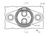
- FIG. 1 is a bottom view of the connector device according to the embodiment.
- FIG. 2 is a top view of the connector device according to the same embodiment.
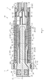
- FIG. 3 is a sectional view taken along line 3-3 in FIG.
- FIG. 4 is a sectional view taken along line 4-4 in FIG.
- FIG. 5 is a cross-sectional view of the first connector of the connector device.
- FIG. 6 is a cross-sectional view of the second connector of the connector device.
- the connectors of this disclosure are [1] A connector device having a first connector and a second connector connected to the first connector, wherein the first connector is concentric with the first positive electrode terminal and the first positive positive terminal. It has a first negative electrode terminal that is staggered in the connection direction between the first connector and the second connector, and the second connector is concentric with the second positive electrode terminal and the second positive electrode terminal. It has a second negative electrode terminal that is staggered in the connection direction between the first connector and the second connector.
- the first positive electrode terminal and the first negative electrode terminal arranged concentrically in the first connector and staggered in the connection direction are arranged concentrically in the second connector and in the connection direction. It can be connected to the second positive electrode terminal and the second negative electrode terminal which are staggered in the above.
- the positive electrode terminal and the negative electrode terminal of each connector are concentric and are arranged so as to be offset in the connection direction. Therefore, as compared with the case where the positive electrode terminal and the negative electrode terminal are arranged side by side in the direction orthogonal to the connection direction. It can contribute to miniaturization.
- one of the terminals of the first connector and the second connector has a plurality of elastic contact pieces that make elastic contact with the terminals of the connector on the other side.
- the elastic contact pieces are bent when the first connector and the second connector are connected by having a plurality of elastic contact pieces, the first connector and the second connector are connected. Easy to make. Further, after the first connector and the second connector are connected, the elastic contact piece makes elastic contact with the connector terminal on the other side, so that connection reliability can be obtained.
- the connector device 10 of the present embodiment electrically connects, for example, the electric vehicle S and the battery B that can be attached to and detached from the electric vehicle S.
- the electric vehicle S is, for example, an electric two-wheeled vehicle such as an electric motorcycle or an electric bicycle.
- the connector device 10 has a first connector 11 electrically connected to the electric vehicle S and a second connector 12 connected to the battery B.
- the first connector 11 is formed in the first housing 20 having the first central axis CL1 extending in the connection direction Z1 between the first connector 11 and the second connector 12, and the first housing 20. It has a plurality of held first terminals 31 and 32.
- connection direction Z1 is a direction in which the second connector 12 is moved relative to the first connector 11 when the first connector 11 and the second connector 12 are connected.
- the connection direction Z1 and the first central axis CL1 direction are the same direction.
- the first connector 11 can be arranged in any direction with respect to the vehicle body S1 constituting the electric vehicle S, but in the present embodiment, the first connector 11 and the second connector 12 are connected. In this state, the side where the second connector 12 is located will be described as an upper side, and the side where the first connector 11 is located will be described as a lower side. Further, hereinafter, when simply described as "circumferential direction", it means the circumferential direction of the first central axis CL1.
- 3 and 4 are cross-sectional views of the connector device 10 cut along a plane including the first central axis CL1.
- the first housing 20 includes a base portion 21, a cylindrical outer tubular portion 22, and a holding portion 23 inside the outer tubular portion 22 that holds the first terminals 31 and 32.
- the first housing 20 is made of an insulating resin material.
- the base portion 21 has a disc-shaped base main body 25 and a nut accommodating portion 26 for accommodating a nut N located on the lower end surface 25a side of the base main body 25.
- the base body 25 is inserted and fixed in the insertion hole provided in the vehicle S with the rubber ring 27 attached to the outer periphery thereof.
- the outer tubular portion 22 extends from the outer peripheral side of the upper end surface 25b of the base main body 25.
- the holding unit 23 includes a first holding unit 28 and a second holding unit 29.
- the first holding portion 28 is configured so as to form a columnar shape as a whole.
- the first holding portion 28 is the center of the outer tubular portion 22 and extends from the upper end surface 25b of the base body 25 in the same direction as the outer tubular portion 22.
- the first holding portion 28 has a main body portion 28a and a retaining portion 28b.
- the main body portion 28a is configured to form a columnar shape, has a constant cross-sectional area cut in a direction (diameter direction) orthogonal to the longitudinal direction from the upper end (base end) to the lower end (tip), and is cut in the same direction.
- the cross-sectional shape is the same in the longitudinal direction.
- the retaining portion 28b is provided at the lower end of the main body portion 28a, and its base end portion is larger in the radial direction than the main body portion 28a.
- the radial direction referred to here is a direction orthogonal to the longitudinal direction of the first holding portion 28.
- the radial direction here is a direction orthogonal to the vertical direction.
- the retaining portion 28b gradually becomes smaller in the radial direction from its own base end portion to the tip end portion.
- the tip of the retaining portion 28b is smaller in the radial direction than the main body portion 28a.
- the second holding portion 29 is configured so as to have a tubular shape as a whole.
- the second holding portion 29 is located outside the first holding portion 28 and inside the outer tubular portion 22.
- the second holding portion 29 has a main body portion 29a and a retaining portion 29b.
- the main body 29a is configured to form a cylindrical shape, and has a constant opening area in a cross section cut in a direction (diameter) orthogonal to the longitudinal direction from the upper end (base end) to the lower end (tip) in the same direction.
- the cross-sectional shape cut into two has the same shape in the longitudinal direction.
- the retaining portion 29b is provided at the lower end of the main body portion 29a, and its base end portion is larger in the radial direction than the main body portion 29a.
- the radial direction referred to here is a direction orthogonal to the longitudinal direction of the second holding portion 29. That is, the radial direction referred to here is a direction orthogonal to the vertical direction.
- the retaining portion 29b gradually becomes smaller in the radial direction from its own base end portion to the tip end portion. The tip of the retaining portion 29b is smaller in the radial direction than the main body portion 29a.
- the first terminals 31 and 32 include a first inner terminal 31 and a first outer terminal 32 located on the outer peripheral side of the first inner terminal 31.
- the first inner terminal 31 has a cylindrical portion 33 fixed to the first holding portion 28 and a lead-out portion 34 derived from the cylindrical portion 33.
- the cylindrical portion 33 covers the outside of the main body portion 28a of the first holding portion 28.
- the inner diameter of the cylindrical portion 33 is the same as the outer diameter of the main body portion 28a. In other words, the inner diameter of the cylindrical portion 33 is smaller than the outer diameter at the base end of the retaining portion 28b. Therefore, it is possible to prevent the first inner terminal 31 including the cylindrical portion 33 from falling off from the retaining portion 28b.
- the lead-out portion 34 extends further downward from the lower end portion in the axial direction of the cylindrical portion 33. At this time, the lead-out portion 34 penetrates the base main body 25 and extends to the nut accommodating portion 26.
- a harness (not shown) is connected to the lead-out unit 34. This harness is connected to the inverter of the vehicle S. As a result, the first inner terminal 31 is electrically connected to the electric vehicle S (inverter constituting the electric vehicle S in the present embodiment) via the harness.
- the first outer terminal 32 has a cylindrical portion 35 fixed to the second holding portion 29 and a lead-out portion 36 derived from the cylindrical portion 35.
- the first outer terminal 32 is arranged concentrically around the first inner terminal 31 and the first central axis CL1.
- the cylindrical portion 35 covers the outside of the main body portion 29a of the second holding portion 29.
- the inner diameter of the cylindrical portion 35 is the same as the outer diameter of the main body portion 29a. In other words, the inner diameter of the cylindrical portion 35 is smaller than the outer diameter at the base end of the retaining portion 29b. Therefore, it is possible to prevent the first outer terminal 32 including the cylindrical portion 35 from falling off from the retaining portion 29b.
- the out-licensing portion 36 extends further downward from the lower end portion in the axial direction of the cylindrical portion 35. At this time, the lead-out portion 36 penetrates the base body 25 and extends to the nut accommodating portion 26.
- a harness (not shown) is connected to the lead-out unit 36. This harness is connected to the inverter of the vehicle S. As a result, the first outer terminal 32 is electrically connected to the electric vehicle S (inverter constituting the electric vehicle S in the present embodiment) via the harness.
- One of the first inner terminal 31 and the first outer terminal 32 configured as described above is the first positive electrode terminal, and the other is the first negative electrode terminal. More specifically, when the positive electrode side of the inverter and the first inner terminal 31 are connected via a harness, and the negative electrode side of the inverter and the first outer terminal 32 are connected via a harness, the first inner terminal 31 is connected. It corresponds to the first positive electrode terminal, and the first outer terminal 32 corresponds to the first negative electrode terminal. Further, when the positive electrode side of the inverter is connected to the first outer terminal 32 via the harness and the negative electrode side of the inverter is connected to the first inner terminal 31 via the harness, the first outer terminal 32 is the first positive electrode terminal. The first inner terminal 31 corresponds to the first negative electrode terminal.
- the cylindrical portion 33 of the first inner terminal 31 is longer in the vertical direction than the cylindrical portion 35 of the first outer terminal 32. Further, the cylindrical portion 35 covers the outside of the cylindrical portion 33. Therefore, only the portion X1 in which the cylindrical portion 33 is relatively long with respect to the cylindrical portion 35 is exposed, and the portion X1 can be connected to the terminal of the second connector 12 on the other side.
- the cylindrical portion 35 that covers the outside of the cylindrical portion 33 has a structure in which the entire cylindrical portion 35 is exposed, and the entire cylindrical portion 35 can be connected to the terminal of the second connector 12 on the other side. That is, the first inner terminal 31 and the first outer terminal 32 of the present embodiment are configured to be displaced in the connection direction Z1 when only the exposed portion is viewed.
- the second connector 12 has a second housing 41 having a second central axis CL2 extending in the connection direction Z1 and a plurality of second terminals 51 and 52 held in the second housing 41. ..
- the second central axis CL2 is located coaxially with the first central axis CL1 when the first connector 11 and the second connector 12 are connected.
- the second housing 41 includes a tubular outer housing 42, an inner housing 43, and a retainer 44 attached to the outer housing 42.
- the second housing 41 is made of an insulating resin material.
- the outer housing 42 is configured to have openings 42a and 42b at both ends to form a cylindrical shape, and a retainer 44 is attached to one of the openings 42a.
- a terminal of the harness H on the battery B side is introduced into the opening 42a of the outer housing 42.
- the other opening 42b of the outer housing 42 is smaller than the opening 42a.
- the inner housing 43 has openings 43a and 43b at both ends, respectively, and is configured to form a cylindrical shape.
- the axial length (length in the opening direction) of the inner housing 43 is smaller than the axial length (length in the opening direction) of the outer housing 42.
- the radial length of the inner housing 43 (the length in the direction orthogonal to the opening direction) is smaller than the radial length (the length in the opening direction) of the outer housing 42.
- the inner housing 43 is housed in the outer housing 42.
- the opening 43a of the inner housing 43 is larger than the other opening 43b.
- the second terminals 51 and 52 include a second inner terminal 51 and a second outer terminal 52 located on the outer peripheral side of the second inner terminal 51.
- the second inner terminal 51 has a cylindrical connecting portion 53, a connecting portion 54 extending from the lower end of the connecting portion 53, and a leading portion 55 extending from the upper end of the connecting portion 53.
- the connecting portion 53 has a plurality of elastic contact pieces 57 formed by forming slits 56 notched along the opening direction at equal intervals in the circumferential direction.
- the connecting portion 53 of the present embodiment has, for example, four elastic contact pieces 57 (only three are shown in FIG. 6). The number of elastic contact pieces 57 may be changed as appropriate.
- Each elastic contact piece 57 has a contact portion 58 located on the tip end side when the connecting portion 53 side is the base end. Each elastic contact piece 57 is inclined so that each contact portion 58 of the elastic contact pieces 57 is closest to the second central axis CL2. Each elastic contact piece 57 has an introduction portion 59 on the tip side of the contact portion 58. The introduction portion 59 is inclined so as to be separated from the second central axis CL2 by the contact portion 58. More specifically, the introduction portion 59 is inclined so as to be gradually separated from the second central axis CL2 toward the tip end side with the contact portion 58 as a base point.
- Each contact portion 58 is arranged concentrically around the second central axis CL2.
- its radial length (length in the direction orthogonal to the central axis CL2) is the first inner terminal. It is slightly smaller than the outer diameter of the cylindrical portion 33 of 31. Therefore, when the first connector 11 and the second connector 12 are connected, each contact portion 58 makes elastic contact with the cylindrical portion 33 side (inner in the radial direction).
- each contact portion 58 is a virtual cylindrical portion centered on the second central axis CL2, its radial length (length in the direction orthogonal to the central axis CL2) is the first holding portion 28. It is slightly longer than the radial length of the tip of the retaining portion 28b. Further, when each contact portion 58 is a virtual cylindrical portion centered on the second central axis CL2, its radial length (length in the direction orthogonal to the central axis CL2) is the first holding portion 28. It is slightly shorter than the radial length of the base end portion of the retaining portion 28b. Further, for this reason, when the first connector 11 and the second connector 12 are connected, extreme interference can be suppressed when the contact portion 58 passes through the retaining portion 28b.
- the lead-out portion 55 is led out from the upper end of the connecting portion 53 in a direction parallel to the second central axis CL2.
- the lead-out portion 55 is connected to the core wire H1 of the harness H at its tip end (upper end).
- the lead-out portion 55 and the core wire H1 can be connected by a known method such as welding or crimping.
- a tubular cover C1 is provided at the connection portion between the lead-out portion 55 and the core wire H1 so as to cover the outside thereof.
- a heat-shrinkable tube can be adopted for example.
- the outer diameter of the second inner terminal 51 is smaller than the inner diameter of the opening 43a of the inner housing 43 and larger than the inner diameter of the opening 43b. Therefore, the second inner terminal 51 introduced from the opening 43a side of the inner housing 43 is prevented from falling off from the opening 43b on the opposite side.
- the second outer terminal 52 includes a cylindrical connecting portion 60, a connecting portion 61 extending from the lower end of the connecting portion 60, and a leading portion 62 extending from the upper end of the connecting portion 60.
- the connecting portion 60 has a plurality of elastic contact pieces 64 formed by forming slits 63 notched in the opening direction (vertical direction) at equal intervals in the circumferential direction.
- the connecting portion 60 of the present embodiment has, for example, eight elastic contact pieces 64 (only four are shown in FIG. 6). The number of elastic contact pieces 64 may be changed as appropriate.
- Each elastic contact piece 64 has a contact portion 65 located on the tip end side when the connecting portion 60 side is the base end. Each elastic contact piece 64 is inclined so that each contact portion 65 of the elastic contact pieces 64 is closest to the second central axis CL2. Each elastic contact piece 64 has an introduction portion 66 on the tip side of the contact portion 65. The introduction portion 66 is inclined so as to be separated from the second central axis CL2 by the contact portion 65. More specifically, the introduction portion 66 is inclined so as to be gradually separated from the second central axis CL2 toward the tip end side with the contact portion 65 as a base point.
- Each contact portion 65 is arranged concentrically around the second central axis CL2.
- its radial length (length in the direction orthogonal to the central axis CL2) is the first outer terminal. It is slightly smaller than the outer diameter of the cylindrical portion 35 of 32. Therefore, when the first connector 11 and the second connector 12 are connected, each contact portion 65 makes elastic contact with the cylindrical portion 35 side (inside in the radial direction).
- each contact portion 65 is a virtual cylindrical portion centered on the second central axis CL2, its radial length (length in the direction orthogonal to the central axis CL2) is the second holding portion 29. It is slightly longer than the radial length of the tip of the retaining portion 29b. Further, when each contact portion 65 is a virtual cylindrical portion centered on the second central axis CL2, its radial length (length in the direction orthogonal to the central axis CL2) is the second holding portion 29. It is slightly shorter than the radial length of the base end portion of the retaining portion 29b. Further, for this reason, when connecting the first connector 11 and the second connector 12, it is possible to suppress extreme interference when the contact portion 65 passes through the retaining portion 29b.
- the lead-out portion 62 is led out from the upper end of the connecting portion 60 in a direction parallel to the second central axis CL2.
- the lead-out portion 62 is connected to the core wire H1 of the harness H at its tip end (upper end).
- the lead-out portion 62 and the core wire H1 can be connected by a known method such as welding or crimping.
- a tubular cover C2 is provided at the connection portion between the lead-out portion 62 and the core wire H1 so as to cover the outside thereof.
- a heat-shrinkable tube can be adopted for example.
- the outer diameter of the second outer terminal 52 is smaller than the inner diameter of the opening 42a of the outer housing 42 and larger than the inner diameter of the opening 42b. Therefore, the second outer terminal 52 introduced from the opening 42a side of the outer housing 42 is prevented from falling off from the opening 42b.
- One of the second inner terminal 51 and the second outer terminal 52 configured as described above is the second positive electrode terminal, and the other is the second negative electrode terminal. More specifically, when the second inner terminal 51 is connected to the positive electrode side of the battery B via the harness H and the second outer terminal 52 is connected to the negative electrode side of the battery B via the harness H, the second The inner terminal 51 corresponds to the second positive electrode terminal, and the second outer terminal 52 corresponds to the second negative electrode terminal. Further, when the second outer terminal 52 is connected to the positive electrode side of the battery B via the harness H and the second inner terminal 51 is connected to the negative electrode side of the battery B via the harness H, the second outer terminal 52 is connected. It corresponds to the second positive electrode terminal, and the second inner terminal 51 corresponds to the second negative electrode terminal.
- the contact portion 58 of the second inner terminal 51 and the contact portion 65 of the second outer terminal 52 are arranged at positions shifted in the connection direction Z1. Specifically, the contact portion 65 of the second outer terminal 52 is located on the downstream side (the first connector side, which is the mating side) in the connection direction Z1 as compared with the contact portion 58 of the second inner terminal.
- the inverter provided in the vehicle S and the battery B are electrically connected by connecting the first connector 11 provided in the vehicle S and the second connector 12 provided in the battery B. Will be done.
- the first inner terminal 31 and the first outer terminal 32 of the first connector 11 are concentric and are arranged so as to be offset in the connection direction Z1.
- the second inner terminal 51 and the second outer terminal 52 of the second connector 12 are concentric and are arranged so as to be offset in the connection direction Z1.
- first inner terminal 31 and the first outer terminal 32 which are concentrically arranged in the first connector 11 in the connection direction Z1, they are arranged concentrically in the second connector 12. It can be connected to the second inner terminal 51 and the second outer terminal 52 which are arranged so as to be offset in the connection direction Z1.
- the inner terminals 31, 51 and the outer terminals 32, 52 of the connectors 11 and 12 are concentric and are arranged so as to be offset in the connection direction Z1. Therefore, it is possible to contribute to the miniaturization of the first connector 11 as compared with the case where the first inner terminal 31 and the first outer terminal 32 are arranged side by side in the direction orthogonal to the connection direction Z1.
- second inner terminal 51 and the second outer terminal 52 are arranged side by side in the direction orthogonal to the connection direction Z1.
- the elastic contact pieces 57 and 64 bend when the first connector 11 and the second connector 12 are connected, so that the first connector 11 and the first connector 11 It is easy to connect to the second connector 12. Further, after the first connector 11 and the second connector 12 are connected, the elastic contact piece makes elastic contact with the terminal of the connector on the other side, so that connection reliability can be obtained.
- the configuration in which the second terminals 51 and 52 of the second connector 12 have a plurality of elastic contact pieces 57 and 64 is adopted, but the present invention is not limited to this.
- the number of elastic contact pieces 57, 64 may be changed as appropriate.
- a configuration may be adopted in which only one of the second terminals 51 and 52 has an elastic contact piece.
- a configuration in which the elastic contact pieces 57 and 64 of the second terminals 51 and 52 are omitted may be adopted.
- a configuration having elastic contact pieces at the first terminals 31 and 32 of the first connector 11 may be adopted.
- the configuration in which the terminals 31 and 32 of the first connector 11 are electrically connected to the inverter is adopted, but the present invention is not limited to this.
- a configuration may be adopted in which the terminals 31 and 32 of the first connector 11 are connected to the electric motor without the terminal 31 and 32 of the first connector 11 via an inverter. In this case, it does not matter whether the vehicle S is equipped with an inverter.
- the first connector 11 is on the vehicle S side and the second connector 12 is on the battery B side, but these relationships may be reversed. That is, the first connector may be on the battery side and the second connector may be on the vehicle side.
- the first connector 11 is fixed to the vehicle body S1.
- the first connector 11 is indirectly fixed to the vehicle body S1 via the device by being fixed to or mounted on the vehicle body S1 such as an inverter. You may.
- the connector device 10 is used, for example, to electrically connect the electric vehicle S, which is an electric motorcycle, and the battery B.
- the electric vehicle that is electrically connected to the battery B by the connector device 10 is not limited to this.
- the electric vehicle may be, for example, an electric tricycle, an electric four-wheeled vehicle, or the like.
- an agricultural vehicle represented by an electric cultivator driven by a replaceable battery can be adopted.
- a connector that is connected to a mating connector and has a positive electrode terminal and a negative electrode terminal that is concentric with the positive electrode terminal and is arranged so as to be offset in the connection direction with the mating connector.
- the positive electrode terminal and the negative electrode terminal of the connector are concentric with each other and are arranged so as to be offset in the connection direction of the mating connector, so that the positive electrode terminal and the negative electrode terminal are orthogonal to the connection direction of the mating connector. It can contribute to the miniaturization of the connector as compared with the case where it is arranged side by side in the direction of
- a connector device having a first connector and a second connector connected to the first connector.
- the first connector has a first positive electrode terminal and a first negative electrode terminal that is concentric with the first positive electrode terminal and is arranged so as to be offset in the connection direction between the first connector and the second connector.
- the second connector has a second positive electrode terminal and a second negative electrode terminal that is concentric with the second positive electrode terminal and is arranged so as to be offset in the connection direction between the first connector and the second connector.
- a connector device in which the first positive electrode terminal is electrically connected to the second positive electrode terminal, and the first negative electrode terminal is electrically connected to the second negative electrode terminal.
- Some implementation examples of the present disclosure include a first connector (11) and a second connector (12) configured to be electrically connected by relative movement in a linear connection direction (Z1). It is aimed at the connector device (10) and
- the first connector (11) is The first polarity, which is one of the positive electrode and the negative electrode, the first central axis (CL1), and the first conductive outer peripheral surface (33) having the first outer diameter. It has a second polarity, which is the other of the positive electrode and the negative electrode, the first central axis (CL1), and a second conductive outer peripheral surface (35) having a second outer diameter larger than the first outer diameter.
- the second connector (12) has one or more first contacts (58) having the first polarity and one or more second contacts (65) having the second polarity.
- first contacts (58) having the first polarity
- second contacts (65) having the second polarity.
- the one or more first contacts (58) of the second connector (12) are along the linear connection direction (Z1) with the first conductive outer peripheral surface (33) of the first connector (11).
- the one or more second contacts (65) of the second connector (12) are linearly sliding contact with the second conductive outer peripheral surface (35) of the first connector (11). Slide contact is made linearly along the connection direction (Z1).
- the first connector (11) is A first cylindrical electrode (31) having a first polarity, which is one of a positive electrode and a negative electrode, It has a second cylindrical electrode (32) having a second polarity, which is the other of the positive electrode and the negative electrode.
- the central axis (CL1) of the first cylindrical electrode (31) and the central axis (CL1) of the second cylindrical electrode (32) coincide with each other.
- the first cylindrical electrode (31) has a first conductive outer peripheral surface (33) having a first outer diameter.
- the second cylindrical electrode (32) has a second conductive outer peripheral surface (35) having a second outer diameter larger than the first outer diameter.
- the second connector (12) has one or more first leaf spring electrodes (51) having the first polarity and one or more second leaf spring electrodes (52) having the second polarity. And When the first connector (11) and the second connector (12) are completely connected, the one or more first leaf spring electrodes (51) of the second connector (12) are the first. The one or more second leaf springs of the second connector (12) come into contact with the first position of the first cylindrical electrode (31) of the connector (11) on the first conductive outer peripheral surface (33). The electrode (52) comes into contact with the second position of the second cylindrical electrode (32) of the first connector (11) on the second conductive outer peripheral surface (35). The second position is separated from the first position in the linear connection direction (Z1).
- the one or more first leaf spring electrodes (51) of the second connector (12) are a plurality of first leaf spring electrodes (51) each having the first polarity.
- the one or more second leaf spring electrodes (52) of the second connector (12) are a plurality of second leaf spring electrodes (52) each having the second polarity.
- the plurality of first leaf spring electrodes (51) of the second connector (12) are aligned on a first virtual circle having a first radius centered on the central axis (CL2) of the second connector (12).
- the plurality of first contacts (58) and the plurality of second contacts (65) are axially along the central axis (CL2) of the second connector (12) and the second connector (12). Are separated in both the radial direction orthogonal to the central axis (CL2) of the above.
Landscapes
- Coupling Device And Connection With Printed Circuit (AREA)
- Details Of Connecting Devices For Male And Female Coupling (AREA)
Abstract
L'invention concerne un dispositif connecteur qui peut contribuer à réduire l'encombrement. Un premier connecteur 11 comprend une première borne interne 31 et une première borne externe 32 qui est concentrique avec la première borne interne 31 et est disposée de manière à être décalée dans la direction Z1 d'une connexion entre le premier connecteur 11 et un second connecteur 12. Le second connecteur 12 comprend une seconde borne interne 51 et une seconde borne externe 52 qui est concentrique avec la seconde borne interne 51 et est disposée de manière à être décalée dans la direction Z1 de la connexion entre le premier connecteur 11 et le second connecteur 12.
Applications Claiming Priority (2)
| Application Number | Priority Date | Filing Date | Title |
|---|---|---|---|
| JP2019-108458 | 2019-06-11 | ||
| JP2019108458A JP2020202091A (ja) | 2019-06-11 | 2019-06-11 | コネクタ装置 |
Publications (1)
| Publication Number | Publication Date |
|---|---|
| WO2020250703A1 true WO2020250703A1 (fr) | 2020-12-17 |
Family
ID=73742820
Family Applications (1)
| Application Number | Title | Priority Date | Filing Date |
|---|---|---|---|
| PCT/JP2020/021179 Ceased WO2020250703A1 (fr) | 2019-06-11 | 2020-05-28 | Dispositif connecteur |
Country Status (2)
| Country | Link |
|---|---|
| JP (1) | JP2020202091A (fr) |
| WO (1) | WO2020250703A1 (fr) |
Citations (4)
| Publication number | Priority date | Publication date | Assignee | Title |
|---|---|---|---|---|
| JPS6185076U (fr) * | 1984-11-08 | 1986-06-04 | ||
| US5007852A (en) * | 1987-03-26 | 1991-04-16 | The British Petroleum Company P.L.C. | Electrical cable assembly |
| JP2006073396A (ja) * | 2004-09-03 | 2006-03-16 | Makoto Kurimoto | 多接点コネクタ |
| US9203184B1 (en) * | 2013-04-11 | 2015-12-01 | Amazon Technologies, Inc. | Self-aligning connector |
-
2019
- 2019-06-11 JP JP2019108458A patent/JP2020202091A/ja not_active Withdrawn
-
2020
- 2020-05-28 WO PCT/JP2020/021179 patent/WO2020250703A1/fr not_active Ceased
Patent Citations (4)
| Publication number | Priority date | Publication date | Assignee | Title |
|---|---|---|---|---|
| JPS6185076U (fr) * | 1984-11-08 | 1986-06-04 | ||
| US5007852A (en) * | 1987-03-26 | 1991-04-16 | The British Petroleum Company P.L.C. | Electrical cable assembly |
| JP2006073396A (ja) * | 2004-09-03 | 2006-03-16 | Makoto Kurimoto | 多接点コネクタ |
| US9203184B1 (en) * | 2013-04-11 | 2015-12-01 | Amazon Technologies, Inc. | Self-aligning connector |
Also Published As
| Publication number | Publication date |
|---|---|
| JP2020202091A (ja) | 2020-12-17 |
Similar Documents
| Publication | Publication Date | Title |
|---|---|---|
| US6477887B1 (en) | Gas sensor having pre-stressed terminal for contact with inserted sensor element | |
| US9281606B2 (en) | Connector for automobile wiring harness | |
| US8827755B2 (en) | High current connector | |
| CN104348322B (zh) | 电动机 | |
| KR20160092941A (ko) | 케이블을 갖는 단자 조립체 및 커넥터 조립체 | |
| JP7000780B2 (ja) | バスバーユニット、モータ | |
| JP2014194844A (ja) | プラグ | |
| WO2019039084A1 (fr) | Dispositif de bague collectrice | |
| US20170018352A1 (en) | Ignition coil for internal combustion engine | |
| JP5673660B2 (ja) | 自動車用内燃機関のための点火装置 | |
| US20250219339A1 (en) | Connection device | |
| CN113675515B (zh) | 导电片、动力电池模块及动力电池箱 | |
| JP2020202091A (ja) | コネクタ装置 | |
| CN109841986B (zh) | 端子结构和电连接器 | |
| JP2013229139A (ja) | 機器直付用シールドコネクタ | |
| CN106450123B (zh) | 用于车载动力电池的连接结构 | |
| JP2017091651A (ja) | ケーブルコネクタ及びハーネス | |
| RU2014153755A (ru) | Цоколь для электрической лампы и способ сборки цоколя для электрической лампы | |
| CN108539481B (zh) | 插口 | |
| JP5800245B2 (ja) | コンデンサ内蔵ジョイントコネクタ | |
| JP6398478B2 (ja) | 内燃機関用の点火コイル | |
| JP2016212976A (ja) | コネクタ付き電線 | |
| CN221596813U (zh) | 端子接触件、端子和电连接装置 | |
| JP2024080956A (ja) | コイルスプリング付き端子 | |
| CN112928516B (zh) | 电接触组件和插孔端子 |
Legal Events
| Date | Code | Title | Description |
|---|---|---|---|
| 121 | Ep: the epo has been informed by wipo that ep was designated in this application |
Ref document number: 20820766 Country of ref document: EP Kind code of ref document: A1 |
|
| NENP | Non-entry into the national phase |
Ref country code: DE |
|
| 122 | Ep: pct application non-entry in european phase |
Ref document number: 20820766 Country of ref document: EP Kind code of ref document: A1 |