WO2020250862A1 - Dispositif de commande pour engin de chantier, engin de chantier, et procédé de commande pour engin de chantier - Google Patents
Dispositif de commande pour engin de chantier, engin de chantier, et procédé de commande pour engin de chantier Download PDFInfo
- Publication number
- WO2020250862A1 WO2020250862A1 PCT/JP2020/022585 JP2020022585W WO2020250862A1 WO 2020250862 A1 WO2020250862 A1 WO 2020250862A1 JP 2020022585 W JP2020022585 W JP 2020022585W WO 2020250862 A1 WO2020250862 A1 WO 2020250862A1
- Authority
- WO
- WIPO (PCT)
- Prior art keywords
- pressure
- work vehicle
- state
- relief
- margin
- Prior art date
- Legal status (The legal status is an assumption and is not a legal conclusion. Google has not performed a legal analysis and makes no representation as to the accuracy of the status listed.)
- Ceased
Links
Images



Classifications
-
- F—MECHANICAL ENGINEERING; LIGHTING; HEATING; WEAPONS; BLASTING
- F16—ENGINEERING ELEMENTS AND UNITS; GENERAL MEASURES FOR PRODUCING AND MAINTAINING EFFECTIVE FUNCTIONING OF MACHINES OR INSTALLATIONS; THERMAL INSULATION IN GENERAL
- F16H—GEARING
- F16H61/00—Control functions within control units of change-speed- or reversing-gearings for conveying rotary motion ; Control of exclusively fluid gearing, friction gearing, gearings with endless flexible members or other particular types of gearing
- F16H61/38—Control of exclusively fluid gearing
- F16H61/40—Control of exclusively fluid gearing hydrostatic
-
- F—MECHANICAL ENGINEERING; LIGHTING; HEATING; WEAPONS; BLASTING
- F16—ENGINEERING ELEMENTS AND UNITS; GENERAL MEASURES FOR PRODUCING AND MAINTAINING EFFECTIVE FUNCTIONING OF MACHINES OR INSTALLATIONS; THERMAL INSULATION IN GENERAL
- F16H—GEARING
- F16H61/00—Control functions within control units of change-speed- or reversing-gearings for conveying rotary motion ; Control of exclusively fluid gearing, friction gearing, gearings with endless flexible members or other particular types of gearing
- F16H61/38—Control of exclusively fluid gearing
- F16H61/40—Control of exclusively fluid gearing hydrostatic
- F16H61/46—Automatic regulation in accordance with output requirements
- F16H61/472—Automatic regulation in accordance with output requirements for achieving a target output torque
-
- E—FIXED CONSTRUCTIONS
- E02—HYDRAULIC ENGINEERING; FOUNDATIONS; SOIL SHIFTING
- E02F—DREDGING; SOIL-SHIFTING
- E02F9/00—Component parts of dredgers or soil-shifting machines, not restricted to one of the kinds covered by groups E02F3/00 - E02F7/00
- E02F9/20—Drives; Control devices
- E02F9/22—Hydraulic or pneumatic drives
- E02F9/2253—Controlling the travelling speed of vehicles, e.g. adjusting travelling speed according to implement loads, control of hydrostatic transmission
-
- E—FIXED CONSTRUCTIONS
- E02—HYDRAULIC ENGINEERING; FOUNDATIONS; SOIL SHIFTING
- E02F—DREDGING; SOIL-SHIFTING
- E02F9/00—Component parts of dredgers or soil-shifting machines, not restricted to one of the kinds covered by groups E02F3/00 - E02F7/00
- E02F9/20—Drives; Control devices
- E02F9/22—Hydraulic or pneumatic drives
- E02F9/2221—Control of flow rate; Load sensing arrangements
- E02F9/2225—Control of flow rate; Load sensing arrangements using pressure-compensating valves
- E02F9/2228—Control of flow rate; Load sensing arrangements using pressure-compensating valves including an electronic controller
-
- E—FIXED CONSTRUCTIONS
- E02—HYDRAULIC ENGINEERING; FOUNDATIONS; SOIL SHIFTING
- E02F—DREDGING; SOIL-SHIFTING
- E02F9/00—Component parts of dredgers or soil-shifting machines, not restricted to one of the kinds covered by groups E02F3/00 - E02F7/00
- E02F9/20—Drives; Control devices
- E02F9/22—Hydraulic or pneumatic drives
- E02F9/2221—Control of flow rate; Load sensing arrangements
- E02F9/2232—Control of flow rate; Load sensing arrangements using one or more variable displacement pumps
- E02F9/2235—Control of flow rate; Load sensing arrangements using one or more variable displacement pumps including an electronic controller
-
- E—FIXED CONSTRUCTIONS
- E02—HYDRAULIC ENGINEERING; FOUNDATIONS; SOIL SHIFTING
- E02F—DREDGING; SOIL-SHIFTING
- E02F9/00—Component parts of dredgers or soil-shifting machines, not restricted to one of the kinds covered by groups E02F3/00 - E02F7/00
- E02F9/20—Drives; Control devices
- E02F9/22—Hydraulic or pneumatic drives
- E02F9/2246—Control of prime movers, e.g. depending on the hydraulic load of work tools
-
- F—MECHANICAL ENGINEERING; LIGHTING; HEATING; WEAPONS; BLASTING
- F16—ENGINEERING ELEMENTS AND UNITS; GENERAL MEASURES FOR PRODUCING AND MAINTAINING EFFECTIVE FUNCTIONING OF MACHINES OR INSTALLATIONS; THERMAL INSULATION IN GENERAL
- F16H—GEARING
- F16H59/00—Control inputs to control units of change-speed- or reversing-gearings for conveying rotary motion
- F16H59/02—Selector apparatus
-
- F—MECHANICAL ENGINEERING; LIGHTING; HEATING; WEAPONS; BLASTING
- F16—ENGINEERING ELEMENTS AND UNITS; GENERAL MEASURES FOR PRODUCING AND MAINTAINING EFFECTIVE FUNCTIONING OF MACHINES OR INSTALLATIONS; THERMAL INSULATION IN GENERAL
- F16H—GEARING
- F16H59/00—Control inputs to control units of change-speed- or reversing-gearings for conveying rotary motion
- F16H59/36—Inputs being a function of speed
- F16H59/44—Inputs being a function of speed dependent on machine speed, e.g. the vehicle speed
-
- F—MECHANICAL ENGINEERING; LIGHTING; HEATING; WEAPONS; BLASTING
- F16—ENGINEERING ELEMENTS AND UNITS; GENERAL MEASURES FOR PRODUCING AND MAINTAINING EFFECTIVE FUNCTIONING OF MACHINES OR INSTALLATIONS; THERMAL INSULATION IN GENERAL
- F16H—GEARING
- F16H59/00—Control inputs to control units of change-speed- or reversing-gearings for conveying rotary motion
- F16H59/50—Inputs being a function of the status of the machine, e.g. position of doors or safety belts
- F16H59/54—Inputs being a function of the status of the machine, e.g. position of doors or safety belts dependent on signals from the brakes, e.g. parking brakes
-
- F—MECHANICAL ENGINEERING; LIGHTING; HEATING; WEAPONS; BLASTING
- F16—ENGINEERING ELEMENTS AND UNITS; GENERAL MEASURES FOR PRODUCING AND MAINTAINING EFFECTIVE FUNCTIONING OF MACHINES OR INSTALLATIONS; THERMAL INSULATION IN GENERAL
- F16H—GEARING
- F16H59/00—Control inputs to control units of change-speed- or reversing-gearings for conveying rotary motion
- F16H59/68—Inputs being a function of gearing status
-
- F—MECHANICAL ENGINEERING; LIGHTING; HEATING; WEAPONS; BLASTING
- F16—ENGINEERING ELEMENTS AND UNITS; GENERAL MEASURES FOR PRODUCING AND MAINTAINING EFFECTIVE FUNCTIONING OF MACHINES OR INSTALLATIONS; THERMAL INSULATION IN GENERAL
- F16H—GEARING
- F16H61/00—Control functions within control units of change-speed- or reversing-gearings for conveying rotary motion ; Control of exclusively fluid gearing, friction gearing, gearings with endless flexible members or other particular types of gearing
- F16H61/02—Control functions within control units of change-speed- or reversing-gearings for conveying rotary motion ; Control of exclusively fluid gearing, friction gearing, gearings with endless flexible members or other particular types of gearing characterised by the signals used
-
- F—MECHANICAL ENGINEERING; LIGHTING; HEATING; WEAPONS; BLASTING
- F16—ENGINEERING ELEMENTS AND UNITS; GENERAL MEASURES FOR PRODUCING AND MAINTAINING EFFECTIVE FUNCTIONING OF MACHINES OR INSTALLATIONS; THERMAL INSULATION IN GENERAL
- F16H—GEARING
- F16H61/00—Control functions within control units of change-speed- or reversing-gearings for conveying rotary motion ; Control of exclusively fluid gearing, friction gearing, gearings with endless flexible members or other particular types of gearing
- F16H61/38—Control of exclusively fluid gearing
- F16H61/40—Control of exclusively fluid gearing hydrostatic
- F16H61/4008—Control of circuit pressure
-
- F—MECHANICAL ENGINEERING; LIGHTING; HEATING; WEAPONS; BLASTING
- F16—ENGINEERING ELEMENTS AND UNITS; GENERAL MEASURES FOR PRODUCING AND MAINTAINING EFFECTIVE FUNCTIONING OF MACHINES OR INSTALLATIONS; THERMAL INSULATION IN GENERAL
- F16H—GEARING
- F16H61/00—Control functions within control units of change-speed- or reversing-gearings for conveying rotary motion ; Control of exclusively fluid gearing, friction gearing, gearings with endless flexible members or other particular types of gearing
- F16H61/38—Control of exclusively fluid gearing
- F16H61/40—Control of exclusively fluid gearing hydrostatic
- F16H61/4008—Control of circuit pressure
- F16H61/4017—Control of high pressure, e.g. avoiding excess pressure by a relief valve
-
- F—MECHANICAL ENGINEERING; LIGHTING; HEATING; WEAPONS; BLASTING
- F16—ENGINEERING ELEMENTS AND UNITS; GENERAL MEASURES FOR PRODUCING AND MAINTAINING EFFECTIVE FUNCTIONING OF MACHINES OR INSTALLATIONS; THERMAL INSULATION IN GENERAL
- F16H—GEARING
- F16H61/00—Control functions within control units of change-speed- or reversing-gearings for conveying rotary motion ; Control of exclusively fluid gearing, friction gearing, gearings with endless flexible members or other particular types of gearing
- F16H61/38—Control of exclusively fluid gearing
- F16H61/40—Control of exclusively fluid gearing hydrostatic
- F16H61/4043—Control of a bypass valve
-
- F—MECHANICAL ENGINEERING; LIGHTING; HEATING; WEAPONS; BLASTING
- F16—ENGINEERING ELEMENTS AND UNITS; GENERAL MEASURES FOR PRODUCING AND MAINTAINING EFFECTIVE FUNCTIONING OF MACHINES OR INSTALLATIONS; THERMAL INSULATION IN GENERAL
- F16H—GEARING
- F16H61/00—Control functions within control units of change-speed- or reversing-gearings for conveying rotary motion ; Control of exclusively fluid gearing, friction gearing, gearings with endless flexible members or other particular types of gearing
- F16H61/38—Control of exclusively fluid gearing
- F16H61/40—Control of exclusively fluid gearing hydrostatic
- F16H61/44—Control of exclusively fluid gearing hydrostatic with more than one pump or motor in operation
-
- F—MECHANICAL ENGINEERING; LIGHTING; HEATING; WEAPONS; BLASTING
- F16—ENGINEERING ELEMENTS AND UNITS; GENERAL MEASURES FOR PRODUCING AND MAINTAINING EFFECTIVE FUNCTIONING OF MACHINES OR INSTALLATIONS; THERMAL INSULATION IN GENERAL
- F16H—GEARING
- F16H61/00—Control functions within control units of change-speed- or reversing-gearings for conveying rotary motion ; Control of exclusively fluid gearing, friction gearing, gearings with endless flexible members or other particular types of gearing
- F16H61/38—Control of exclusively fluid gearing
- F16H61/40—Control of exclusively fluid gearing hydrostatic
- F16H61/46—Automatic regulation in accordance with output requirements
-
- F—MECHANICAL ENGINEERING; LIGHTING; HEATING; WEAPONS; BLASTING
- F16—ENGINEERING ELEMENTS AND UNITS; GENERAL MEASURES FOR PRODUCING AND MAINTAINING EFFECTIVE FUNCTIONING OF MACHINES OR INSTALLATIONS; THERMAL INSULATION IN GENERAL
- F16H—GEARING
- F16H63/00—Control outputs from the control unit to change-speed- or reversing-gearings for conveying rotary motion or to other devices than the final output mechanism
- F16H63/40—Control outputs from the control unit to change-speed- or reversing-gearings for conveying rotary motion or to other devices than the final output mechanism comprising signals other than signals for actuating the final output mechanisms
-
- B—PERFORMING OPERATIONS; TRANSPORTING
- B60—VEHICLES IN GENERAL
- B60Y—INDEXING SCHEME RELATING TO ASPECTS CROSS-CUTTING VEHICLE TECHNOLOGY
- B60Y2200/00—Type of vehicle
- B60Y2200/40—Special vehicles
- B60Y2200/41—Construction vehicles, e.g. graders, excavators
- B60Y2200/415—Wheel loaders
-
- F—MECHANICAL ENGINEERING; LIGHTING; HEATING; WEAPONS; BLASTING
- F16—ENGINEERING ELEMENTS AND UNITS; GENERAL MEASURES FOR PRODUCING AND MAINTAINING EFFECTIVE FUNCTIONING OF MACHINES OR INSTALLATIONS; THERMAL INSULATION IN GENERAL
- F16H—GEARING
- F16H59/00—Control inputs to control units of change-speed- or reversing-gearings for conveying rotary motion
- F16H59/68—Inputs being a function of gearing status
- F16H2059/6838—Sensing gearing status of hydrostatic transmissions
- F16H2059/6861—Sensing gearing status of hydrostatic transmissions the pressures, e.g. high, low or differential pressures
Definitions
- the present invention relates to a work vehicle control device, a work vehicle, and a work vehicle control method.
- the present application claims priority with respect to Japanese Patent Application No. 2019-108554 filed in Japan on June 11, 2019, the contents of which are incorporated herein by reference.
- Patent Document 1 discloses a technique for controlling the pump capacity of the HST in order to reduce the sudden feeling of acceleration generated when the clutch of the 1-pump 2-motor type HST is operated.
- the pressure of the HST circuit of the continuously variable transmission mounted on the work vehicle may increase more than necessary due to various factors.
- the pressure of the HST circuit suddenly changes when the load fluctuates due to work such as excavation or pushing soil or the load fluctuates due to the brake.
- the pressure of the HST circuit rises sharply, the output torque increases more than necessary, and the riding comfort of the work vehicle deteriorates.
- An object of the present invention is to provide a work vehicle control device, a work vehicle, and a work vehicle control method capable of preventing sudden changes in output torque due to load fluctuations of a continuously variable transmission.
- the control device for a work vehicle includes a power source, a traveling device, and a hydrostatic stepless transmission having a relief valve capable of setting a relief pressure, and powers the power source. It is a control device of a work vehicle including a power transmission device for transmitting to the traveling device, and includes a relief pressure setting unit for setting the relief pressure of the relief valve according to a target output value of the traveling device.
- control device of the work vehicle can prevent a sudden change in the output torque due to the load fluctuation of the power transmission device.
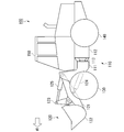
- FIG. 1 is a side view of the work vehicle according to the first embodiment.
- the work vehicle 100 according to the first embodiment is a wheel loader.
- the work vehicle 100 includes a vehicle body 110, a work machine 120, a front wheel portion 130, a rear wheel portion 140, and a driver's cab 150.
- the work vehicle 100 is an example of a power machine.
- the vehicle body 110 includes a front vehicle body 111, a rear vehicle body 112, and a steering cylinder 113.
- the front vehicle body 111 and the rear vehicle body 112 are rotatably attached around a steering axis extending in the vertical direction of the vehicle body 110.
- the front wheel portion 130 is provided below the front vehicle body 111, and the rear wheel portion 140 is provided below the rear vehicle body 112.
- the steering cylinder 113 is a hydraulic cylinder.
- the base end portion of the steering cylinder 113 is attached to the rear vehicle body 112, and the tip end portion is attached to the front vehicle body 111.
- the steering cylinder 113 expands and contracts with hydraulic oil to define the angle between the front vehicle body 111 and the rear vehicle body 112. That is, the steering angle of the front wheel portion 130 is defined by the expansion and contraction of the steering cylinder 113.
- the work machine 120 is used for excavating and transporting work objects such as earth and sand.
- the working machine 120 is provided at the front portion of the vehicle body 110.
- the work machine 120 includes a boom 121, a bucket 122, a bell crank 123, a lift cylinder 124, and a bucket cylinder 125.
- the base end portion of the boom 121 is attached to the front portion of the front vehicle body 111 via a pin.
- the bucket 122 includes a blade for excavating a work object and a container for carrying the excavated work object.
- the base end portion of the bucket 122 is attached to the tip end portion of the boom 121 via a pin.
- the bell crank 123 transmits the power of the bucket cylinder 125 to the bucket 122.
- the first end of the bell crank 123 is attached to the bottom of the bucket 122 via a link mechanism.
- the second end of the bell crank 123 is attached to the tip of the bucket cylinder 125 via a pin.
- the lift cylinder 124 is a hydraulic cylinder.
- the base end portion of the lift cylinder 124 is attached to the front portion of the front vehicle body 111.
- the tip of the lift cylinder 124 is attached to the boom 121.
- the bucket cylinder 125 is a hydraulic cylinder.
- the base end portion of the bucket cylinder 125 is attached to the front portion of the front vehicle body 111.
- the tip of the bucket cylinder 125 is attached to the bucket 122 via the bell crank 123.
- the bucket cylinder 125 expands and contracts due to the hydraulic oil, so that the bucket 122 operates in the tilt direction or the dump direction.
- the driver's cab 150 is a space for the operator to board and operate the work vehicle 100.
- the driver's cab 150 is provided above the rear vehicle body 112.
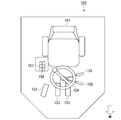
- FIG. 2 is a diagram showing an internal configuration of the driver's cab according to the first embodiment. Inside the driver's cab 150, a seat 151, an accelerator pedal 152, a brake pedal 153, a steering handle 154, a front / rear changeover switch 155, a shift switch 156, a boom lever 157, and a bucket lever 158 are provided inside the driver's cab 150. Inside the driver's cab 150, a seat 151, an accelerator pedal 152, a brake pedal 153, a steering handle 154, a front / rear changeover switch 155, a shift switch 156, a boom lever 157, and a bucket lever 158 are provided.
- the work vehicle 100 may be provided with one brake pedal 153, or may be provided with a plurality of brake pedals 153. For example, when the
- the left brake pedal 153 when viewed from the rear may be assigned the same function as the right brake pedal 153. Further, the left brake pedal 153 and the right brake pedal 153 may be assigned different functions. In this case, the degree of clutch engagement may be changed according to the amount of operation of the left brake pedal 153 so that the clutch is disengaged by, for example, operating the left brake pedal 153.
- the accelerator pedal 152 is operated to set a driving force (traction force) for traveling generated by the work vehicle 100.
- the brake pedal 153 is operated to set the traveling braking force generated by the work vehicle 100. The larger the operating amount of the brake pedal 153, the stronger the braking force is set.
- the steering handle 154 is operated to set the steering angle of the work vehicle 100.
- the front / rear changeover switch 155 is operated to set the traveling direction of the work vehicle 100. The traveling direction of the work vehicle is either forward (F: Forward), reverse (R: Rear), or neutral (N: Neutral).
- the shift switch 156 is operated to set the speed range of the power transmission device.
- the boom lever 157 is operated to set the movement amount of the raising operation or the lowering operation of the boom 121.
- the boom lever 157 accepts a lowering operation when tilted forward, and accepts a raising operation when tilted backward.
- the bucket lever 158 is operated to set the movement amount of the dump operation or tilt operation of the bucket 122.
- the bucket lever 158 accepts a dump operation when tilted forward, and accepts a tilt operation when tilted backward.
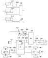
- FIG. 3 is a schematic view showing a power system of the work vehicle according to the first embodiment.
- the work vehicle 100 includes an engine 210, a PTO 220 (Power Take Off), a transmission 230, a front axle 240, a rear axle 250, a variable displacement pump 260, and a fixed capacitance pump 270.
- the engine 210 is, for example, a diesel engine.
- the engine 210 is provided with a fuel injection device 211 and an engine tachometer 2101.
- the fuel injection device 211 controls the driving force of the engine 210 by adjusting the amount of fuel injected into the cylinder of the engine 210.
- the engine tachometer 2101 measures the number of revolutions of the engine 210.
- the PTO 220 transmits a part of the driving force of the engine 210 to the variable displacement pump 260 and the fixed capacitance pump 270. That is, the PTO 220 distributes the driving force of the engine 210 to the transmission 230, the variable displacement pump 260, and the fixed capacitance pump 270.
- the transmission 230 is a continuously variable transmission equipped with HST231 (hydrostatic continuously variable transmission).
- the transmission 230 may be an HMT (hydraulic mechanical continuously variable transmission) that performs shift control only by the HST 231 or a combination of the HST 231 and a planetary gear mechanism.
- the transmission 230 shifts the driving force input to the input shaft and outputs it from the output shaft.
- the input shaft of the transmission 230 is connected to the PTO 220 and the output shaft is connected to the front axle 240 and the rear axle 250. That is, the transmission 230 transmits the driving force of the engine 210 distributed by the PTO 220 to the front axle 240 and the rear axle 250.
- the transmission 230 is provided with an input shaft tachometer 2301 and an output shaft tachometer 2302.
- the input shaft tachometer 2301 measures the rotation speed of the input shaft of the transmission 230.
- the output shaft tachometer 2302 measures the rotation speed of the output shaft of the transmission 230.
- the HST 231 of the transmission 230 is provided with an HST pressure gauge 2303.
- the HST pressure gauge 2303 measures the pressure of the HST 231.
- the front axle 240 transmits the driving force output by the transmission 230 to the front wheel portion 130. As a result, the front wheel portion 130 rotates.
- the rear axle 250 transmits the driving force output by the transmission 230 to the rear wheel portion 140. As a result, the rear wheel portion 140 rotates.
- the front axle 240 and the rear axle 250 are examples of traveling devices.
- the variable displacement pump 260 is driven by a driving force from the engine 210.
- the discharge capacity of the variable displacement pump 260 is changed, for example, by controlling the tilt angle of the swash plate provided in the variable capacitance pump 260.
- the hydraulic oil discharged from the variable displacement pump 260 is supplied to the lift cylinder 124 and the bucket cylinder 125 via the control valve 261 and is supplied to the steering cylinder 113 via the steering valve 262.
- the control valve 261 controls the flow rate of the hydraulic oil discharged from the variable displacement pump 260, and distributes the hydraulic oil to the lift cylinder 124 and the bucket cylinder 125.
- the steering valve 262 controls the flow rate of the hydraulic oil supplied to the steering cylinder 113.
- the variable displacement pump 260 is provided with a first pump pressure gauge 2601 and a pump capacitance meter 2602.
- the first pump pressure gauge 2601 measures the discharge pressure of hydraulic oil from the variable displacement pump 260.
- the pump capacity meter 2602 measures the capacity of the variable capacity pump 260 based on the swash plate angle of the variable capacity pump 260 and the like.
- the variable displacement pump 260 is an example of a device that distributes power from the PTO 220. In other embodiments, the variable displacement pump 260 may consist of a plurality of pumps, or in place of or in addition to the variable displacement pump 260, with other destinations such as hydraulically driven fans (not shown). Good.
- the lift cylinder 124 is provided with a lift pressure sensor 2603. The lift pressure sensor 2603 measures the bottom pressure of the lift cylinder 124.
- the fixed capacity pump 270 is driven by the driving force from the engine 210.
- the hydraulic oil discharged from the fixed capacity pump 270 is supplied to the brake valve 271 in the transmission 230.
- the brake valve 271 controls the pressure of hydraulic oil supplied to a brake cylinder (not shown) built in each axle.
- the fixed capacity pump 270 is provided with a second pump pressure gauge 2701.
- the second pump pressure gauge 2701 measures the discharge pressure of hydraulic oil from the fixed capacity pump 270.
- the fixed capacity pump 270 is an example of a device that distributes power from the PTO 220.
- the fixed capacity pump 270 may be composed of a plurality of pumps, or may have a supply destination such as a lubrication circuit (not shown).
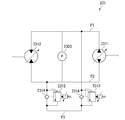
- FIG. 4 is a diagram showing a configuration of an HST included in the transmission according to the first embodiment.
- the HST 231 includes an HST pump 2311, an HST motor 2312, a first relief valve 2313, a first check valve 2314, a second relief valve 2315, and a second check valve 2316.
- the HST pump 2311 and the HST motor 2312 are connected to each other via the first hydraulic path P1 and the second hydraulic path P2.
- the HST pump 2311 supplies hydraulic oil to the HST motor 2312 via the first hydraulic path P1 or the second hydraulic path P2.
- the HST motor 2312 is driven by hydraulic oil supplied from the HST pump 2311.
- the first relief valve 2313 connects the first hydraulic path P1 and the relief bypass P3.
- the pressure in the first hydraulic path P1 is higher than that in the second hydraulic path P2 and the differential pressure exceeds a predetermined relief pressure
- the hydraulic oil flowing through the first hydraulic path P1 is passed through the relief bypass P3.
- the first check valve 2314 is provided in parallel with the first relief valve 2313, stops the hydraulic oil flowing from the first hydraulic path P1, and passes the hydraulic oil flowing from the relief bypass P3 to the first hydraulic path P1.
- the second relief valve 2315 connects the second hydraulic path P2 and the relief bypass P3.
- the pressure in the second hydraulic path P2 is higher than that in the first hydraulic path P1 and the differential pressure exceeds a predetermined relief pressure
- the hydraulic oil flowing through the second hydraulic path P2 is passed through the relief bypass P3.
- the second check valve 2316 is provided in parallel with the second relief valve 2315, stops the hydraulic oil flowing from the second hydraulic path P2, and passes the hydraulic oil flowing from the relief bypass P3 to the second hydraulic path P2.
- the hydraulic oil flowing through the first hydraulic path P1 is the first relief valve 2313, the relief bypass. It flows to the second hydraulic path P2 via P3 and the second check valve 2316.
- the hydraulic oil flowing through the second hydraulic path P2 is the second relief valve 2315, the relief bypass. It flows to the first hydraulic path P1 via P3 and the first check valve 2314.
- a hydraulic pump (not shown) for supplying the hydraulic oil to the relief bypass P3 may be provided.
- the relief pressures of the first relief valve 2313 and the second relief valve 2315 can be changed by a control signal.
- the first relief valve 2313 and the second relief valve 2315 may include a solenoid that pushes a spring that closes the valve, and may set the relief pressure by changing the position of the solenoid by an electric current.
- the HST pressure gauge 2303 measures the differential pressure between the first hydraulic path P1 and the second hydraulic path P2.
- the differential pressure between the first hydraulic path P1 and the second hydraulic path P2 is determined by the difference between the measured values of the two pressure sensors provided with pressure sensors provided in each of the first hydraulic path P1 and the second hydraulic path P2. It may be measured.
- the work vehicle 100 includes a control device 300 for controlling the work vehicle 100.
- the control device 300 is provided in the vehicle body 110, preferably in the driver's cab 150.
- the control device 300 responds to the amount of operation of each operating device (accelerator pedal 152, brake pedal 153, steering handle 154, front / rear changeover switch 155, shift switch 156, boom lever 157, bucket lever 158) in the driver's cab 150.
- a control signal is output to the fuel injection device 211, the transmission 230, the variable displacement pump 260, and the control valve 261.
- FIG. 5 is a schematic block diagram showing a configuration of a control device for a work vehicle according to the first embodiment.
- the control device 300 is a computer including a processor 310, a main memory 330, a storage 350, and an interface 370.
- the storage 350 is a tangible storage medium that is not temporary. Examples of the storage 350 include HDD (Hard Disk Drive), SSD (Solid State Drive), magnetic disk, magneto-optical disk, CD-ROM (Compact Disc Read Only Memory), and DVD-ROM (Digital Versatile Disc Read Only Memory). , Semiconductor memory and the like.
- the storage 350 may be internal media directly connected to the bus of the control device 300, or external media connected to the control device 300 via the interface 370 or a communication line.
- the storage 350 stores a program for controlling the work vehicle 100.
- the program may be for realizing a part of the functions exerted by the control device 300.
- the program may exert its function in combination with another program already stored in the storage 350, or in combination with another program mounted on another device.
- the control device 300 may include a custom LSI (Large Scale Integrated Circuit) such as a PLD (Programmable Logic Device) in addition to or in place of the above configuration.
- PLDs include PAL (Programmable Array Logic), GAL (Generic Array Logic), CPLD (Complex Programmable Logic Device), and FPGA (Field Programmable Gate Array).
- PLDs Programmable Logic Device
- PAL Programmable Array Logic
- GAL Generic Array Logic
- CPLD Complex Programmable Logic Device
- FPGA Field Programmable Gate Array
- the distributed control device 300 may expand the program in the main memory 330 and execute the above processing. Further, the program may be for realizing a part of the above-mentioned functions. Further, the program may be a so-called difference file (difference program) that realizes the above-mentioned function in combination with another program already stored in the storage 350.
- difference file difference program
- the processor 310 executes the operation amount acquisition unit 311, the measurement value acquisition unit 312, the vehicle state calculation unit 313, the required PTO torque determination unit 314, the required output torque determination unit 315, the traveling load estimation unit 316, and the work.
- the operation amount acquisition unit 311 acquires the operation amount from each of the accelerator pedal 152, the brake pedal 153, the steering handle 154, the front / rear changeover switch 155, the shift switch 156, the boom lever 157, and the bucket lever 158.
- the operation amount of the accelerator pedal 152 is the accelerator operation amount
- the operation amount of the brake pedal 153 is the brake operation amount
- the operation amount of the steering handle 154 is the steering operation amount
- the value corresponding to the operation position of the front / rear changeover switch 155 is the FNR operation amount.
- the value corresponding to the operation position of the shift switch 156 is referred to as the shift operation amount
- the operation amount of the boom lever 157 is referred to as the boom operation amount
- the operation amount of the bucket lever 158 is referred to as the bucket operation amount.
- the measurement value acquisition unit 312 includes a fuel injection device 211, an engine tachometer 2101, an input shaft tachometer 2301, an output shaft tachometer 2302, an HST pressure gauge 2303, a first pump pressure gauge 2601, a pump capacity meter 2602, and a lift pressure sensor 2603. And the measured value is acquired from the second pump pressure gauge 2701. That is, the measured value acquisition unit 312 uses the fuel injection amount of the engine 210, the rotation speed of the engine 210, the rotation speed of the input shaft of the transmission 230, the rotation speed of the output shaft of the transmission 230, the pressure of the HST231, and the variable displacement pump 260. The measured values of the pump pressure, the capacity of the variable capacity pump 260, the bottom pressure of the lift cylinder 124, and the pump pressure of the fixed capacity pump 270 are acquired.
- the vehicle state calculation unit 313 uses the output torque of the engine 210, the upper limit torque of the engine 210, the angular acceleration of the engine 210, and the variable capacity pump 260 and the fixed capacity pump 270 with the PTO 220.
- the torque distributed to (PTO torque), the input / output speed ratio of the transmission 230, the angular acceleration of the output shaft of the transmission 230, and the traveling speed of the work vehicle 100 are calculated.
- the output torque of the engine 210 is the torque actually exerted by the engine 210 calculated based on the fuel injection amount.
- the upper limit torque of the engine 210 is the maximum torque that the engine 210 can exert.
- the requested PTO torque determination unit 314 includes the steering operation amount, boom operation amount, and bucket operation amount acquired by the operation amount acquisition unit 311 and the pump pressure of the variable capacity pump 260 acquired by the measurement value acquisition unit 312, and the variable capacity pump 260.
- the required value (required PTO torque) of the torque distributed from the PTO 220 to the variable capacity pump 260 and the fixed capacity pump 270 is determined based on the capacity of the pump and the measured value of the pump pressure of the fixed capacity pump 270.
- the required PTO torque determination unit 314 obtains the required flow rate of the variable displacement pump 260 from the steering operation amount based on the PTO conversion function that defines the relationship between the operation amount and the required flow rate.
- the required PTO torque determination unit 314 obtains the required flow rate of the variable displacement pump 260 from the boom operation amount and the bucket operation amount based on the PTO conversion function. Then, the required PTO torque determination unit 314 is based on the measured values of the pump pressure of the variable capacity pump 260, the capacity of the variable capacity pump 260, and the pump pressure of the fixed capacity pump 270, and the specified flow rate of the variable capacity pump 260. , Determine the required PTO torque.
- the required output torque determination unit 315 shifts gears based on the accelerator operation amount, brake operation amount, shift operation amount, and FNR operation amount acquired by the operation amount acquisition unit 311 and the traveling speed calculated by the vehicle state calculation unit 313.
- the required value (required output torque) of the torque of the output shaft of the machine 230 is determined.
- the required output torque determination unit 315 determines the required output torque from the traveling speed calculated by the vehicle state calculation unit 313 based on the traveling conversion function that defines the relationship between the traveling speed and the required output torque.
- the required output torque determination unit 315 determines the characteristics of the travel conversion function based on the accelerator operation amount, the brake operation amount, the shift operation amount, and the FNR operation amount.
- the required output torque determination unit 315 specifies the travel conversion function corresponding to the speed range specified by the shift operation amount among the plurality of travel conversion functions corresponding to the plurality of speed ranges.
- the required output torque determination unit 315 transforms the specified travel conversion function based on the magnification related to the accelerator operation amount.
- the required output torque determination unit 315 transforms the specified travel conversion function based on the magnification related to the brake operation amount.
- the required output torque determination unit 315 determines the sign of the required output torque based on the FNR manipulated variable.
- the transmission 230 exerts the torque on the braking side.
- the required output torque becomes a value on the braking side. Therefore, when the traveling speed calculated by the vehicle state calculation unit 313 exceeds the upper limit of the speed range specified by the shift operation amount, the accelerator operation amount, and the brake operation amount, the required output torque determination unit 315 increases the required output torque. It is the value on the braking side (the sign opposite to the running speed).
- the mileage estimation unit 316 uses the output torque Teng of the engine 210 calculated by the vehicle state calculation unit 313, the angular acceleration ⁇ - eng of the engine 210, the PTO torque T PTO , the input / output speed ratio i of the transmission 230, and the transmission 230.
- the traveling load torque T load related to traveling is estimated based on the angular acceleration ⁇ out of the output shaft.
- the traveling load torque T load can be calculated based on the following equation (1).
- I eng is the moment of inertia of the engine 210.
- I v is the moment of inertia of the work vehicle 100.
- ⁇ t is the torque efficiency of the transmission 230.
- N is an axle reduction ratio between the output shaft of the transmission 230 and the front wheels 130 and the rear wheels 140.
- the moment of inertia I eng , the moment of inertia I v , the torque efficiency ⁇ t , and the axle reduction ratio N are constants.
- Equation (1) includes equation (2) showing the relationship between the output torque T eng of the engine 210 and the output torque T out of the transmission 230, the output torque T out of the transmission 230, and the acceleration ⁇ of the work vehicle 100. It can be derived from the equation (3) showing the relationship with out .
- the traveling load torque T load may be calculated based on an equation other than the equation (1). For example, instead of equation (2), the pressure of HST231 measured by HST231, the capacity command of the variable capacity pump of HST231, the pump capacity measured by the pump capacity meter provided in the variable capacity pump, and the output torque T out .
- An equation for specifying the traveling load torque T load may be derived by using an equation showing the relationship between.
- an equation for specifying the traveling load torque T load is derived by using the torque command of the electric motor and the electric motor output torque estimated from the voltage / current. You may.
- the work state specifying unit 317 specifies the work state of the work vehicle 100 based on the operation amount acquired by the operation amount acquisition unit 311 and the measurement value acquired by the measurement value acquisition unit 312.
- the working state values are, for example, "low speed running state”, “high speed running state”, “excavation state”, and "braking state”.
- the "low speed running state” is a state in which the work vehicle 100 is running at a low speed. For example, when the absolute value of the traveling speed is less than a predetermined value, the working state specifying unit 317 may determine that the working state is the “low speed traveling state”. Further, the work state specifying unit 317 may determine that the work state is the "low speed running state” when, for example, the shift operation amount is the first speed or the second speed.
- the “high-speed running state” is a state in which the work vehicle 100 is moving forward or backward.
- the working state specifying unit 317 may determine that the working state is the "high-speed running state", for example, when the absolute value of the traveling speed is equal to or higher than a predetermined value. Further, the work state specifying unit 317 may determine that the work state is the "high-speed running state” when, for example, the shift operation amount is the third speed or the fourth speed.
- the “excavation state” is a state in which the work vehicle 100 is excavating by the work machine 120.
- the work state specifying unit 317 may determine that the work state is the "excavation state” when, for example, the measured value of the bottom pressure of the lift cylinder 124 is equal to or higher than a predetermined value.
- the "braking state” is a state in which the work vehicle 100 is braking.
- the work state specifying unit 317 may determine that the work state is the "braking state", for example, when the brake operation amount is larger than 0.
- the target rotation speed determination unit 318 includes the required running power calculated from the required output torque and the running speed, the required PTO torque, and the required engine output which is the sum of the required PTO output calculated from the measured value of the engine 210 rotation speed. Based on, the target engine speed used for controlling the engine 210 is determined.
- the target engine speed determination unit 318 determines the target engine speed based on a rotation speed conversion function that defines the relationship between the required engine output and the engine speed, which is determined in advance by design or the like.
- the rotation speed conversion function may be designed to suppress the rotation of the engine 210 to the low rotation speed side as much as possible within a range in which the required engine output can be exhibited and the engine acceleration is not hindered.
- the target rotation speed determination unit 318 determines the engine rotation speed (PTO required rotation speed) required to realize the required flow rate of the variable displacement pump 260 calculated by the required PTO torque determination unit 314.
- the target rotation speed determination unit 318 determines the required PTO rotation speed based on a rotation speed conversion function that defines the relationship between the required flow rate of the variable displacement pump 260 and the engine rotation speed, which is determined in advance by design or the like.
- the target engine speed determining unit 318 determines the target engine speed to be the PTO required speed.
- the acceleration torque specifying unit 319 sets the engine 210 at the target engine speed based on the measured value of the engine 210 rotation speed acquired by the measured value acquisition unit 312 and the target engine speed determined by the target rotation speed determination unit 318. Calculate the target acceleration torque required for rotation. That is, the acceleration torque specifying unit 319 determines the target engine acceleration from the rotation speed of the difference between the measured value of the rotation speed of the engine 210 and the target engine rotation speed, and multiplies the target engine acceleration by the moment of inertia of the engine 210. Then, calculate the target acceleration torque.
- the target engine torque determination unit 320 includes the PTO torque calculated by the vehicle state calculation unit 313, the upper limit torque of the engine 210, the input / output speed ratio of the transmission 230, and the required output torque determined by the required output torque determination unit 315.
- the target engine torque which is the torque to be output by the engine 210, is determined based on the measured value of the rotation speed of the engine 210.
- the target engine torque determining unit 320 calculates the required input torque, which is the torque of the engine 210 required to obtain the required output torque, by multiplying the required output torque by the input / output speed ratio of the transmission 230.
- the target engine torque determination unit 320 determines the sum of the PTO torque and the required input torque and the smaller of the maximum values of the engine torque as the target engine torque.
- the engine control unit 321 outputs an engine torque command to the fuel injection device 211. Specifically, the engine control unit 321 outputs an engine torque command indicating the target engine torque determined by the target engine torque determination unit 320.
- the target HST pressure specifying unit 322 determines the pressure of the HST 231 corresponding to the required output torque determined by the required output torque determining unit 315 as the target HST pressure (target circuit pressure) which is the control target of the HST 231.
- the relationship between the output torque of the transmission 230 and the pressure of the HST 231 is determined by the relationship of the gear ratio between the output shaft and the HST motor 2312 determined by the design of the transmission 230 and the capacity of the HST motor 2312 at that time. To. That is, the target HST pressure decreases as the capacity of the HST motor 2312 increases, and increases as the required output torque increases.
- the margin determining unit 323 allows the difference between the relief pressure of the first relief valve 2313 and the second relief valve 2315 and the target HST pressure based on the working state of the work vehicle 100 specified by the work state specifying unit 317. Determine the margin pressure to be.
- the margin pressure is determined in advance for each working condition. When the margin pressures related to each working state are arranged in ascending order, they are the margin pressure related to the braking state, the margin pressure related to the excavation state, the margin pressure related to the low speed running state, and the margin pressure related to the high speed running state.
- the margin pressure related to the braking state may be set to monotonically decrease with respect to the amount of depression of the brake pedal 153. Further, when it is desired to apply a strong braking force, the margin pressure related to the braking state may be set to a negative number.
- the relief pressure setting unit 324 is the sum of the relief pressures of the first relief valve 2313 and the second relief valve 2315 of the HST 231 to the target HST pressure specified by the target HST pressure specifying unit 322 and the margin pressure determined by the margin determining unit 323. Set to.
- the target speed ratio determination unit 325 determines the measured value of the rotation speed of the input shaft of the transmission 230, the measured value of the rotation speed of the output shaft of the transmission 230, the traveling load torque estimated by the traveling load estimation unit 316, and the required output torque.
- the target input / output speed ratio of the transmission 230 is determined based on the target output torque determined by the unit 315 and the target engine acceleration specified by the acceleration torque specifying unit 319.
- the target speed ratio determination unit 325 of the transmission 230 after the lapse of time related to a predetermined control cycle is based on the rotation speed of the output shaft of the transmission 230, the traveling load torque, and the target output torque. Estimate the rotation speed of the output shaft and set it as the target rotation speed of the output shaft.
- the target speed ratio determination unit 325 estimates the rotation speed of the input shaft of the transmission 230 after the lapse of time related to a predetermined control cycle based on the rotation speed of the input shaft of the transmission 230 and the target engine acceleration. Is set as the target rotation speed of the input shaft. The target speed ratio determination unit 325 determines the target input / output speed ratio by dividing the target rotation speed of the output shaft by the target rotation speed of the input shaft.
- the transmission control unit 326 outputs a control command for the transmission 230 in order to realize the target input / output speed ratio determined by the target speed ratio determination unit 325.
- the transmission control unit 326 outputs, for example, the capacity command of the HST 231 included in the transmission 230.
- the pump control unit 327 outputs a control command for the variable displacement pump 260 in order to realize the required PTO torque determined by the required PTO torque determination unit 314.
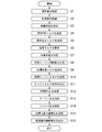
- FIG. 6 is a flowchart showing a control method of the work vehicle according to the first embodiment.
- the operation amount acquisition unit 311 acquires the operation amount from each of the accelerator pedal 152, the brake pedal 153, the steering handle 154, the front / rear changeover switch 155, the shift switch 156, the boom lever 157, and the bucket lever 158 (step S1).
- the measurement value acquisition unit 312 includes a fuel injection device 211, an engine tachometer 2101, an input shaft tachometer 2301, an output shaft tachometer 2302, an HST pressure gauge 2303, a first pump pressure gauge 2601, a pump capacity meter 2602, and a second. The measured value is acquired from the pump pressure gauge 2701 (step S2).
- the vehicle state calculation unit 313 describes the output torque of the engine 210, the upper limit torque of the engine 210, the angular acceleration of the engine 210, the PTO torque, and the input / output speed ratio of the transmission 230 based on the measured values acquired in step S2. , The angular acceleration of the output shaft of the transmission 230 and the traveling speed of the work vehicle 100 are calculated (step S3).
- the required PTO torque determination unit 314 determines the steering operation amount, boom operation amount, and bucket operation amount acquired in step S1, the pump pressure and capacity of the variable capacity pump 260 acquired in step S2, and the pump pressure of the fixed capacity pump 270.
- the required PTO torque is determined based on the measured value of (step S4).
- the required output torque determination unit 315 determines the required output torque based on the operation amount related to traveling acquired in step S1 and the traveling speed calculated in step S3 (step S5).
- the traveling load estimation unit 316 estimates the traveling load torque based on the value of the vehicle state calculated in step S3 (step S6).
- the work state specifying unit 317 specifies the work state of the work vehicle 100 based on the operation amount acquired in step S1 and the measured value acquired in step S2 (step S7). That is, the work state specifying unit 317 specifies whether the work state is a "low speed running state", a "high speed running state”, an "excavation state", or a "braking state”.
- the target rotation speed determination unit 318 is the required engine output which is the sum of the required running power calculated from the required output torque and the running speed, and the required PTO output calculated from the required PTO torque and the measured value of the engine 210 rotation speed.
- the target engine speed is determined based on (step S8).
- the acceleration torque specifying unit 319 calculates the target acceleration torque based on the measured value of the engine speed of the engine 210 and the target engine speed determined in step S8 (step S9).
- the target engine torque determination unit 320 determines the required output torque, the PTO torque calculated in step S3, the upper limit torque of the engine, the input / output speed ratio of the transmission 230, and the measured value of the rotation speed of the engine 210 acquired in step S2.
- the target engine torque is determined based on (step S10).
- the engine control unit 321 outputs an engine torque command indicating the target engine torque determined in step S10 (step S11).
- the target HST pressure specifying unit 322 determines the target HST pressure based on the required output torque determined in step S5 and the capacity command of the latest HST motor 2312 (step S12).
- the margin determination unit 323 determines the margin pressure based on the working state of the work vehicle 100 specified in step S7 (step S13).
- the relief pressure setting unit 324 sets the relief pressures of the first relief valve 2313 and the second relief valve 2315 of the HST 231 to the sum of the target HST pressure determined in step S12 and the margin pressure determined in step S13 ( Step S14).
- the target speed ratio determination unit 325 sets a target based on the measured value of the rotation speed of the input shaft of the transmission 230, the measured value of the rotation speed of the output shaft of the transmission 230, the load torque, the target output torque, and the target engine acceleration.
- the output speed ratio is determined (step S15).
- the transmission control unit 326 outputs a control command for the transmission 230 for achieving the target input / output speed ratio (step S16).
- the control device 300 executes the above-mentioned control process at predetermined control cycles.
- FIG. 7 is a diagram showing an example of setting the relief pressure according to the first embodiment.
- the relief pressure HST_relief can be obtained by adding the margin pressure P HST_margin to the target HST pressure P HST_target .
- the work vehicle 100 starts traveling at time T0.
- the traveling speed of the work vehicle 100 reaches a threshold speed for classifying the low-speed traveling state and the high-speed traveling state at time T1.
- the work state specifying unit 317 specifies that the work state of the work vehicle 100 is the low-speed running state from the time T0 to the time T1.
- the margin determination unit 323 determines the margin pressure PHST_margin to be added to the target HST pressure PHST_taget as the margin pressure related to the low-speed running state.
- the control device 300 can prevent the pressure of the HST 231 from deviating significantly from the target HST pressure P HST_taget .
- the traveling speed of the work vehicle 100 further increases.
- the work state specifying unit 317 specifies that the work state of the work vehicle 100 is the high-speed traveling state from the time T1 to the time T2. Therefore, the margin determination unit 323 determines the margin pressure PHST_margin to a value larger than that in the low-speed running state.
- the control device 300 can reduce the relief loss of the HST 231 by setting the margin pressure PHST_margin to a larger value than in the low-speed running state.
- the control device 300 can positively promote the relief of the hydraulic oil and suppress the traction force to improve the braking performance.
- the work vehicle continues to travel at a speed less than the threshold speed.
- the work state specifying unit 317 specifies that the work state of the work vehicle 100 is the low-speed running state from the time T3 to the time T4. Therefore, the margin determination unit 323 determines the margin pressure PHST_margin as the margin pressure related to low-speed running.
- the margin pressure P HST_margin from time T3 to time T4 is the same value as the margin pressure P HST_margin from time T0 to time T1.
- the control device 300 can prevent the engine speed from decreasing and the vehicle from popping out by setting the margin pressure PHST_margin to a value smaller than that in the low-speed running state.
- FIG. 8 is a diagram showing the effect of setting the relief pressure by the control device according to the first embodiment.
- the control device 300 according to the first embodiment sets the relief pressures P HST_relief of the first relief valve 2313 and the second relief valve 2315 according to the target HST pressure P HST_target .
- the relief pressures PHST_relief of the first relief valve 2313 and the second relief valve 2315 to be set may have the same value.
- the internal pressure P HST of the HST 231 can be suppressed to a pressure equal to or lower than the target HST pressure P HST_target . Therefore, according to the first embodiment, it is possible to prevent a sudden change in the output torque due to a load fluctuation of the transmission 230.
- FIG. 8 also discloses behavior when not set relief pressure P HST_relief as a comparative example, if you do not set the relief pressure P HST_relief, the internal pressure P HST_cp of HST231 increases greatly according to the load variation I understand. After that, the control device 300 controls the internal pressure of the HST 231 so as to approach the target HST pressure PHST_target , so that the internal pressure swings back. This swinging back causes the pitch of the vehicle body to sway, which reduces the riding comfort.
- the engine speed is remarkably lowered immediately after the load fluctuation occurs. This is because a sudden load is transmitted from the HST 231 to the engine 210.
- the first embodiment it is possible to prevent the load from being transmitted to the engine 210 by the relief of the HST231 and suppress the decrease in the engine speed.
- the work vehicle 100 according to the first embodiment is a wheel loader, but is not limited to this.
- the work vehicle 100 according to another embodiment may be another work vehicle 100 such as a bulldozer and a tractor.
- the control device 300 may be applied to a power machine other than the work vehicle.
- control device 300 sets the relief pressure based on the target HST pressure regardless of the working state, but is not limited to this in other embodiments.
- control device 300 may not set the relief pressure when the working state is the high-speed running state, but may set the relief pressure when the working state is the other state.
- control device 300 has a different margin pressure depending on the working state, but the present invention is not limited to this.
- control device 300 may always set the relief pressure using the same margin pressure.
- control device of the work vehicle can prevent sudden changes in output torque due to load fluctuations of the power transmission device.
- Fixed capacity pump 211 Fuel injection device 2101 ... Engine rotation meter 231 ... HST 2301 ... Input shaft rotation meter 2302 ... Output shaft rotation meter 2303 ... HST pressure gauge 261 ... Control valve 262 ... Steering valve 2601 ... 1st pump pressure gauge 2602 ... Pump capacity meter 2603 ... Lift pressure sensor 271 ... Brake valve 2701 ... 2nd pump pressure gauge 300 ... Control device 310 ... Processor 330 ... Main memory 350 ... Storage 370 ... Interface 2311 ... HST pump 2312 ... HST motor 2313 ... 1st relief valve 2314 ... 1st check valve 2315 ... 2nd relief valve 2316 ... 2nd check valve 311 ...
- Operation amount acquisition unit 312 ... Measurement value acquisition unit 313 ... Vehicle condition calculation unit 314 ... Request PTO torque determination unit 315 ... Required output torque determination unit 316 ... Travel load estimation unit 317 ... Working state specification unit 318 ... Target rotation speed determination unit 319 ... Acceleration torque specification unit 320 ... Target engine torque determination unit 321 ... Engine control unit 322 ... Target HST pressure specification unit 323 ... Margin determination unit 324 ... Relief pressure setting unit 325 ... Target speed ratio determination unit 326 ... Transmission control unit
Landscapes
- Engineering & Computer Science (AREA)
- General Engineering & Computer Science (AREA)
- Mechanical Engineering (AREA)
- Mining & Mineral Resources (AREA)
- Civil Engineering (AREA)
- Structural Engineering (AREA)
- Physics & Mathematics (AREA)
- Fluid Mechanics (AREA)
- Operation Control Of Excavators (AREA)
- Control Of Fluid Gearings (AREA)
Abstract
La présente invention concerne un engin de chantier qui comprend: une source de puissance; un dispositif de déplacement; et un dispositif de transmission de puissance qui transmet une puissance de la source de puissance au dispositif de déplacement. Le dispositif de transmission de puissance comprend une transmission hydrostatique à variation continue ayant une soupape de décharge pour laquelle une pression de détente peut être réglée. Ce dispositif de commande pour un engin de chantier comprend une unité de réglage de la pression de détente qui règle la pression de détente de la soupape de détente en fonction d'une valeur de sortie cible du dispositif de déplacement.
Priority Applications (3)
| Application Number | Priority Date | Filing Date | Title |
|---|---|---|---|
| US17/605,742 US11795663B2 (en) | 2019-06-11 | 2020-06-08 | Control device of work vehicle, work vehicle, and control method for work vehicle |
| EP20822124.2A EP3951102B1 (fr) | 2019-06-11 | 2020-06-08 | Dispositif de commande pour engin de chantier, engin de chantier, et procédé de commande pour engin de chantier |
| CN202080035800.0A CN113825932B (zh) | 2019-06-11 | 2020-06-08 | 作业车辆的控制装置、作业车辆、及作业车辆的控制方法 |
Applications Claiming Priority (2)
| Application Number | Priority Date | Filing Date | Title |
|---|---|---|---|
| JP2019-108554 | 2019-06-11 | ||
| JP2019108554A JP7197433B2 (ja) | 2019-06-11 | 2019-06-11 | 作業車両の制御装置、作業車両、および作業車両の制御方法 |
Publications (1)
| Publication Number | Publication Date |
|---|---|
| WO2020250862A1 true WO2020250862A1 (fr) | 2020-12-17 |
Family
ID=73742589
Family Applications (1)
| Application Number | Title | Priority Date | Filing Date |
|---|---|---|---|
| PCT/JP2020/022585 Ceased WO2020250862A1 (fr) | 2019-06-11 | 2020-06-08 | Dispositif de commande pour engin de chantier, engin de chantier, et procédé de commande pour engin de chantier |
Country Status (5)
| Country | Link |
|---|---|
| US (1) | US11795663B2 (fr) |
| EP (1) | EP3951102B1 (fr) |
| JP (1) | JP7197433B2 (fr) |
| CN (1) | CN113825932B (fr) |
| WO (1) | WO2020250862A1 (fr) |
Cited By (1)
| Publication number | Priority date | Publication date | Assignee | Title |
|---|---|---|---|---|
| US20220090676A1 (en) * | 2017-11-07 | 2022-03-24 | Hyster-Yale Group, Inc. | Continuously variable transmission control |
Families Citing this family (3)
| Publication number | Priority date | Publication date | Assignee | Title |
|---|---|---|---|---|
| JP7512232B2 (ja) * | 2021-05-21 | 2024-07-08 | 株式会社クボタ | 作業機 |
| JP7770183B2 (ja) * | 2021-12-24 | 2025-11-14 | 株式会社クボタ | 電動作業車 |
| EP4286708A4 (fr) * | 2022-03-18 | 2025-01-08 | Hitachi Construction Machinery Co., Ltd. | Dispositif de transmission de puissance pour véhicule |
Citations (7)
| Publication number | Priority date | Publication date | Assignee | Title |
|---|---|---|---|---|
| JPH06174073A (ja) * | 1992-12-09 | 1994-06-21 | Toyota Motor Corp | 車両用ベルト式無段変速機の油圧制御装置 |
| JPH0932045A (ja) * | 1995-05-17 | 1997-02-04 | Komatsu Ltd | 油圧駆動式作業車両の油圧回路 |
| JP2008032109A (ja) * | 2006-07-28 | 2008-02-14 | Aisin Seiki Co Ltd | ロックアップクラッチの制御装置 |
| JP2012231331A (ja) | 2011-04-26 | 2012-11-22 | Kyocera Corp | 携帯通信機器 |
| JP2013117242A (ja) * | 2011-12-01 | 2013-06-13 | Toyota Motor Corp | 車両用油圧制御装置 |
| WO2017043459A1 (fr) * | 2015-09-09 | 2017-03-16 | ジヤトコ株式会社 | Dispositif et procédé de commande hydraulique d'une transmission à variation continue de véhicule |
| JP2019108554A (ja) | 2013-09-30 | 2019-07-04 | ユー ピー エム キュンメネ コーポレーション | リグニンの反応性を増加させるための方法 |
Family Cites Families (14)
| Publication number | Priority date | Publication date | Assignee | Title |
|---|---|---|---|---|
| JP2580483B2 (ja) * | 1994-02-18 | 1997-02-12 | 株式会社小松製作所 | 静油圧−機械式変速機の制御装置 |
| DE69620463T2 (de) | 1995-05-17 | 2002-10-31 | Komatsu Ltd., Tokio/Tokyo | Hydraulischer kreislauf für hydraulisch angetriebene arbeitsfahrzeuge |
| JP3462690B2 (ja) * | 1997-02-07 | 2003-11-05 | 株式会社クボタ | 建機の油圧回路 |
| JP3539335B2 (ja) | 2000-03-10 | 2004-07-07 | トヨタ自動車株式会社 | 無段変速機を備えた車両の制御装置 |
| JP3876220B2 (ja) * | 2002-12-10 | 2007-01-31 | 新キャタピラー三菱株式会社 | 作業機械の自動昇圧装置 |
| JP4503482B2 (ja) * | 2005-04-12 | 2010-07-14 | 株式会社クボタ | 作業機の油圧システム |
| JP2008196564A (ja) | 2007-02-09 | 2008-08-28 | Toyota Motor Corp | 無段変速機の油圧制御装置 |
| JP4805973B2 (ja) | 2008-05-09 | 2011-11-02 | 株式会社クボタ | 刈取収穫機の刈取部昇降構造 |
| JP4990334B2 (ja) * | 2009-09-03 | 2012-08-01 | 株式会社小松製作所 | 作業車両 |
| EP2530208A4 (fr) | 2010-01-28 | 2017-08-09 | Hitachi Construction Machinery Co., Ltd. | Machine de travail hydraulique |
| JP5092060B1 (ja) * | 2012-03-30 | 2012-12-05 | 株式会社小松製作所 | 作業車両及び作業車両の制御方法 |
| JP2014119108A (ja) * | 2012-12-19 | 2014-06-30 | Kubota Corp | 作業車 |
| JP6201019B2 (ja) * | 2016-08-25 | 2017-09-20 | 京楽産業.株式会社 | 遊技機 |
| CN108291635A (zh) * | 2016-11-11 | 2018-07-17 | 株式会社小松制作所 | 作业机械 |
-
2019
- 2019-06-11 JP JP2019108554A patent/JP7197433B2/ja active Active
-
2020
- 2020-06-08 EP EP20822124.2A patent/EP3951102B1/fr active Active
- 2020-06-08 WO PCT/JP2020/022585 patent/WO2020250862A1/fr not_active Ceased
- 2020-06-08 CN CN202080035800.0A patent/CN113825932B/zh not_active Expired - Fee Related
- 2020-06-08 US US17/605,742 patent/US11795663B2/en active Active
Patent Citations (7)
| Publication number | Priority date | Publication date | Assignee | Title |
|---|---|---|---|---|
| JPH06174073A (ja) * | 1992-12-09 | 1994-06-21 | Toyota Motor Corp | 車両用ベルト式無段変速機の油圧制御装置 |
| JPH0932045A (ja) * | 1995-05-17 | 1997-02-04 | Komatsu Ltd | 油圧駆動式作業車両の油圧回路 |
| JP2008032109A (ja) * | 2006-07-28 | 2008-02-14 | Aisin Seiki Co Ltd | ロックアップクラッチの制御装置 |
| JP2012231331A (ja) | 2011-04-26 | 2012-11-22 | Kyocera Corp | 携帯通信機器 |
| JP2013117242A (ja) * | 2011-12-01 | 2013-06-13 | Toyota Motor Corp | 車両用油圧制御装置 |
| JP2019108554A (ja) | 2013-09-30 | 2019-07-04 | ユー ピー エム キュンメネ コーポレーション | リグニンの反応性を増加させるための方法 |
| WO2017043459A1 (fr) * | 2015-09-09 | 2017-03-16 | ジヤトコ株式会社 | Dispositif et procédé de commande hydraulique d'une transmission à variation continue de véhicule |
Cited By (2)
| Publication number | Priority date | Publication date | Assignee | Title |
|---|---|---|---|---|
| US20220090676A1 (en) * | 2017-11-07 | 2022-03-24 | Hyster-Yale Group, Inc. | Continuously variable transmission control |
| US11549585B2 (en) * | 2017-11-07 | 2023-01-10 | Hyster-Yale Group, Inc. | Continuously variable transmission control |
Also Published As
| Publication number | Publication date |
|---|---|
| US20220220704A1 (en) | 2022-07-14 |
| US11795663B2 (en) | 2023-10-24 |
| EP3951102B1 (fr) | 2025-11-26 |
| EP3951102A4 (fr) | 2022-06-22 |
| CN113825932B (zh) | 2023-07-25 |
| JP2020200676A (ja) | 2020-12-17 |
| CN113825932A (zh) | 2021-12-21 |
| EP3951102A1 (fr) | 2022-02-09 |
| JP7197433B2 (ja) | 2022-12-27 |
Similar Documents
| Publication | Publication Date | Title |
|---|---|---|
| CN103429875B (zh) | 作业车辆的驱动控制装置 | |
| CN113056592B (zh) | 作业车辆、动力机械的控制装置及控制方法 | |
| CN101287899B (zh) | 建筑车辆 | |
| JP5192605B1 (ja) | ホイールローダ | |
| WO2020250862A1 (fr) | Dispositif de commande pour engin de chantier, engin de chantier, et procédé de commande pour engin de chantier | |
| CN113874638B (zh) | 动力传递装置的控制装置、动力传递装置及动力传递装置的控制方法 | |
| JP7265345B2 (ja) | 作業車両、作業車両の制御装置および制御方法 | |
| JP7845855B2 (ja) | 作業車両、作業車両の制御装置、および作業車両の制御方法 | |
| JP7236917B2 (ja) | 作業車両、作業車両の制御装置および制御方法 |
Legal Events
| Date | Code | Title | Description |
|---|---|---|---|
| 121 | Ep: the epo has been informed by wipo that ep was designated in this application |
Ref document number: 20822124 Country of ref document: EP Kind code of ref document: A1 |
|
| ENP | Entry into the national phase |
Ref document number: 2020822124 Country of ref document: EP Effective date: 20211027 |
|
| NENP | Non-entry into the national phase |
Ref country code: DE |
|
| WWG | Wipo information: grant in national office |
Ref document number: 2020822124 Country of ref document: EP |