WO2020252806A1 - 一种事件数据流的处理方法及计算设备 - Google Patents
一种事件数据流的处理方法及计算设备 Download PDFInfo
- Publication number
- WO2020252806A1 WO2020252806A1 PCT/CN2019/093215 CN2019093215W WO2020252806A1 WO 2020252806 A1 WO2020252806 A1 WO 2020252806A1 CN 2019093215 W CN2019093215 W CN 2019093215W WO 2020252806 A1 WO2020252806 A1 WO 2020252806A1
- Authority
- WO
- WIPO (PCT)
- Prior art keywords
- inertial measurement
- attitude angle
- event data
- measurement parameters
- data stream
- Prior art date
- Legal status (The legal status is an assumption and is not a legal conclusion. Google has not performed a legal analysis and makes no representation as to the accuracy of the status listed.)
- Ceased
Links
Images




Classifications
-
- G—PHYSICS
- G06—COMPUTING OR CALCULATING; COUNTING
- G06T—IMAGE DATA PROCESSING OR GENERATION, IN GENERAL
- G06T7/00—Image analysis
- G06T7/80—Analysis of captured images to determine intrinsic or extrinsic camera parameters, i.e. camera calibration
-
- G—PHYSICS
- G06—COMPUTING OR CALCULATING; COUNTING
- G06T—IMAGE DATA PROCESSING OR GENERATION, IN GENERAL
- G06T7/00—Image analysis
- G06T7/70—Determining position or orientation of objects or cameras
- G06T7/73—Determining position or orientation of objects or cameras using feature-based methods
-
- G—PHYSICS
- G01—MEASURING; TESTING
- G01C—MEASURING DISTANCES, LEVELS OR BEARINGS; SURVEYING; NAVIGATION; GYROSCOPIC INSTRUMENTS; PHOTOGRAMMETRY OR VIDEOGRAMMETRY
- G01C25/00—Manufacturing, calibrating, cleaning, or repairing instruments or devices referred to in the other groups of this subclass
-
- G—PHYSICS
- G01—MEASURING; TESTING
- G01C—MEASURING DISTANCES, LEVELS OR BEARINGS; SURVEYING; NAVIGATION; GYROSCOPIC INSTRUMENTS; PHOTOGRAMMETRY OR VIDEOGRAMMETRY
- G01C19/00—Gyroscopes; Turn-sensitive devices using vibrating masses; Turn-sensitive devices without moving masses; Measuring angular rate using gyroscopic effects
- G01C19/56—Turn-sensitive devices using vibrating masses, e.g. vibratory angular rate sensors based on Coriolis forces
- G01C19/5783—Mountings or housings not specific to any of the devices covered by groups G01C19/5607 - G01C19/5719
-
- G—PHYSICS
- G01—MEASURING; TESTING
- G01C—MEASURING DISTANCES, LEVELS OR BEARINGS; SURVEYING; NAVIGATION; GYROSCOPIC INSTRUMENTS; PHOTOGRAMMETRY OR VIDEOGRAMMETRY
- G01C21/00—Navigation; Navigational instruments not provided for in groups G01C1/00 - G01C19/00
- G01C21/10—Navigation; Navigational instruments not provided for in groups G01C1/00 - G01C19/00 by using measurements of speed or acceleration
- G01C21/12—Navigation; Navigational instruments not provided for in groups G01C1/00 - G01C19/00 by using measurements of speed or acceleration executed aboard the object being navigated; Dead reckoning
- G01C21/16—Navigation; Navigational instruments not provided for in groups G01C1/00 - G01C19/00 by using measurements of speed or acceleration executed aboard the object being navigated; Dead reckoning by integrating acceleration or speed, i.e. inertial navigation
- G01C21/165—Navigation; Navigational instruments not provided for in groups G01C1/00 - G01C19/00 by using measurements of speed or acceleration executed aboard the object being navigated; Dead reckoning by integrating acceleration or speed, i.e. inertial navigation combined with non-inertial navigation instruments
- G01C21/1656—Navigation; Navigational instruments not provided for in groups G01C1/00 - G01C19/00 by using measurements of speed or acceleration executed aboard the object being navigated; Dead reckoning by integrating acceleration or speed, i.e. inertial navigation combined with non-inertial navigation instruments with passive imaging devices, e.g. cameras
-
- G—PHYSICS
- G01—MEASURING; TESTING
- G01C—MEASURING DISTANCES, LEVELS OR BEARINGS; SURVEYING; NAVIGATION; GYROSCOPIC INSTRUMENTS; PHOTOGRAMMETRY OR VIDEOGRAMMETRY
- G01C25/00—Manufacturing, calibrating, cleaning, or repairing instruments or devices referred to in the other groups of this subclass
- G01C25/005—Manufacturing, calibrating, cleaning, or repairing instruments or devices referred to in the other groups of this subclass initial alignment, calibration or starting-up of inertial devices
-
- H—ELECTRICITY
- H04—ELECTRIC COMMUNICATION TECHNIQUE
- H04N—PICTORIAL COMMUNICATION, e.g. TELEVISION
- H04N23/00—Cameras or camera modules comprising electronic image sensors; Control thereof
- H04N23/60—Control of cameras or camera modules
- H04N23/68—Control of cameras or camera modules for stable pick-up of the scene, e.g. compensating for camera body vibrations
- H04N23/681—Motion detection
- H04N23/6812—Motion detection based on additional sensors, e.g. acceleration sensors
-
- H—ELECTRICITY
- H04—ELECTRIC COMMUNICATION TECHNIQUE
- H04N—PICTORIAL COMMUNICATION, e.g. TELEVISION
- H04N23/00—Cameras or camera modules comprising electronic image sensors; Control thereof
- H04N23/60—Control of cameras or camera modules
- H04N23/68—Control of cameras or camera modules for stable pick-up of the scene, e.g. compensating for camera body vibrations
- H04N23/682—Vibration or motion blur correction
- H04N23/683—Vibration or motion blur correction performed by a processor, e.g. controlling the readout of an image memory
-
- H—ELECTRICITY
- H04—ELECTRIC COMMUNICATION TECHNIQUE
- H04N—PICTORIAL COMMUNICATION, e.g. TELEVISION
- H04N25/00—Circuitry of solid-state image sensors [SSIS]; Control thereof
- H04N25/47—Image sensors with pixel address output; Event-driven image sensors; Selection of pixels to be read out based on image data
-
- G—PHYSICS
- G06—COMPUTING OR CALCULATING; COUNTING
- G06T—IMAGE DATA PROCESSING OR GENERATION, IN GENERAL
- G06T2207/00—Indexing scheme for image analysis or image enhancement
- G06T2207/10—Image acquisition modality
- G06T2207/10016—Video; Image sequence
-
- G—PHYSICS
- G06—COMPUTING OR CALCULATING; COUNTING
- G06T—IMAGE DATA PROCESSING OR GENERATION, IN GENERAL
- G06T2207/00—Indexing scheme for image analysis or image enhancement
- G06T2207/30—Subject of image; Context of image processing
- G06T2207/30244—Camera pose
Definitions
- the present invention relates to the technical field of data processing, in particular to a processing scheme for event data streams.
- the dynamic vision sensor is a biological mimic vision sensor that simulates the human retina based on pulse-triggered neurons.
- Each pixel unit in the sensor can independently respond to and record areas of rapid changes in light intensity.
- an event-triggered processing mechanism Using an event-triggered processing mechanism, its output is no longer an image frame, but an asynchronous digital event stream.
- the sensor can also output nine-axis IMU (Inertial Measurement Unit) data including accelerometer, gyroscope, and magnetometer.
- IMU Inertial Measurement Unit
- the traditional IMU compensation scheme based on VIO is mainly to operate on the entire image, by obtaining a frame of image, combining the corresponding IMU data to calculate the corresponding transformation matrix, and then obtaining the corresponding Pose estimation to solve the problem of screen jitter.
- the current DVS edge sharpening algorithm mainly relies on the estimation of the target depth of field. This kind of algorithm is generally complex and time-consuming.
- the present invention provides a processing method and computing device for event data stream, in an attempt to solve or at least alleviate at least one of the above problems.
- a method for processing an event data stream comes from a dynamic vision sensor.
- the method includes the steps of: acquiring inertial measurement parameters corresponding to a segment of event data stream used to generate a frame of image; Determine the attitude angle data based on the acquired inertial measurement parameters and the calibration parameters of the dynamic vision sensor; generate a transformation matrix based on the determined attitude angle data; use the transformation matrix to process a section of event data stream to generate processed event data flow.
- the method according to the present invention further includes the step of: using the generated processed event data stream to generate an image containing motion information.
- the step of obtaining inertial measurement parameters corresponding to a piece of event data stream used to generate a frame of image includes: judging the first duration of generating a frame of image and outputting a set of inertial measurement parameters Whether the second duration of the parameter is consistent; if the first duration is consistent with the second duration, obtain the two sets of inertial measurement parameters in the time period corresponding to the first duration or the second duration; if the first duration and the second duration are inconsistent and the first duration If the duration is an integer multiple of the second duration, obtain multiple sets of inertial measurement parameters in the time period corresponding to the first duration; if the first duration is inconsistent with the second duration and the first duration is not an integer multiple of the second duration, the acquisition is greater than The multiple sets of inertial measurement parameters in the time period corresponding to the first duration, and the obtained inertial measurement parameters are used to interpolate the multiple sets of inertial measurement parameters within the time period corresponding to the first duration.
- the step of determining the attitude angle data includes: based on the calibration parameters and each group of inertial measurement parameters within the first time period , Respectively determine the attitude angle data corresponding to each group of inertial measurement parameters.
- the step of generating a transformation matrix further includes: respectively calculating the difference of the attitude angle data corresponding to each group of inertial measurement parameters to obtain at least one attitude angle Difference: Based on the calculated at least one attitude angle difference, at least one transformation matrix is generated.
- a transformation matrix is used to process a segment of event data stream, and the step of generating the processed event data stream includes: using at least one generated transformation matrix to perform processing on at least one of the event data streams.
- the location of the event data is processed separately to generate the location of the processed event data.
- the inertial measurement parameters include gyroscope three-axis data, accelerometer three-axis data, and magnetometer three-axis data.
- the step of determining the attitude angle data further includes: using the calibration parameters of the dynamic vision sensor to compare the acquired inertial measurement The parameters are processed to obtain the processed inertial measurement parameters.
- the processed inertial measurement parameters include processed gyroscope three-axis data, processed accelerometer three-axis data, and processed magnetometer three-axis data; use time difference integral pair
- the processed gyroscope three-axis data is processed to generate the gyroscope attitude angle;
- the trigonometric function is used to process the processed accelerometer three-axis data and the processed magnetometer three-axis data distribution to generate accelerometer attitude angle and magnetic force respectively Gauge attitude angle;
- the gyroscope attitude angle, accelerometer attitude angle and magnetometer attitude angle are processed separately to generate the final attitude angle.
- the difference of the attitude angle data corresponding to each group of inertial measurement parameters is calculated, and the step of obtaining at least one attitude angle difference includes: calculating the attitude of the other groups of inertial measurement parameters separately The difference between the angle data and the attitude angle data of the first set of inertial measurement parameters.
- the method according to the present invention further includes the step of calibrating the dynamic vision sensor to determine the calibration parameters of the dynamic vision sensor.
- the step of calibrating the dynamic vision sensor to determine the calibration parameters of the dynamic vision sensor includes: calibrating the camera parameters of the dynamic vision sensor to determine the center pixel corresponding to the dynamic vision sensor Position and focal length parameters; inertial measurement unit calibration for dynamic vision sensors to determine inertial calibration parameters.
- the transformation matrix is generated according to the following formula:
- ⁇ roll, ⁇ pan, and ⁇ tilt are the attitude angle differences
- cx, cy, and f represent the center pixel position and focal length of the image respectively.
- the step of using a transformation matrix to process a piece of event data includes:
- x_compensated warpMatrix(0,0) ⁇ x+warpMatrix(0,1) ⁇ y+warpMatrix(0,2)
- y_compensated warpMatrix(1,0) ⁇ x+warpMatrix(1,1) ⁇ y+warpMatrix(1,2)
- x and y are the locations of the original event data
- x_compensated and y_compensated are the locations of the processed event data.
- a dynamic vision sensor including: an event detection unit, adapted to output event data streams; an inertial measurement unit, adapted to output inertial measurement parameters; and a motion compensation unit, respectively, and the event detection unit It is coupled with the inertial measurement unit and is suitable for processing the event data stream based on the inertial measurement parameters to generate the processed event data stream.
- the dynamic vision sensor according to the present invention further includes a framing unit, which is coupled to the motion compensation unit, and is adapted to generate an image containing motion information according to the processed event data stream.
- a computing device including: one or more processors; and a memory; one or more programs, wherein one or more programs are stored in the memory and configured to be operated by one or Executed by multiple processors, one or more programs include instructions for executing any of the methods described above.
- a computer-readable storage medium storing one or more programs.
- the one or more programs include instructions.
- the computing device executes the steps in the method described above. Any method.
- the attitude angle data is calculated through the acquired inertial measurement parameters, and then the attitude angle data is used to process the event data stream output by the dynamic vision sensor.
- the algorithm is simple and effective, and does not depend on the target depth of field. Estimated, so it will not cause serious time-consuming.
- the image generated based on the processed event data stream can effectively reduce the tailing phenomenon and keep the image clear.
- FIG. 1 shows a schematic diagram of a dynamic vision sensor 100 according to some embodiments of the present invention
- FIG. 2 shows a schematic diagram of a computing device 200 according to some embodiments of the present invention
- FIG. 3 shows a flowchart of a method 300 for processing an event data stream according to an embodiment of the present invention
- FIGS. 4A to 4C show schematic diagrams of the relationship between the first duration and the second duration according to some embodiments of the present invention.
- FIG. 5 shows a schematic diagram of attitude angle data according to an embodiment of the present invention
- Fig. 6 shows a schematic flowchart of determining attitude angle data according to an embodiment of the present invention.
- FIG. 7A and FIG. 7B are schematic diagrams showing the comparison of optical flow images before and after processing according to an embodiment of the present invention.
- DVS Dynamic Vision Sensors
- the sensor has a pixel unit array composed of a plurality of pixel units, and each pixel unit responds to and records the area where the light intensity changes rapidly only when it senses a change in light intensity.
- the specific composition of the dynamic vision sensor is not elaborated here. Since DVS uses an event-triggered processing mechanism, its output is an asynchronous event data stream.
- the event data stream is, for example, light intensity change information (eg, light intensity change timestamp and light intensity threshold) and the coordinate position of the triggered pixel unit .
- Fig. 1 shows a schematic diagram of a dynamic vision sensor 100 according to an embodiment of the present invention.
- the dynamic vision sensor 100 includes an event detection unit 110 for outputting event data streams, an inertial measurement unit 120 for outputting inertial measurement parameters, and a motion compensation unit 130.
- the motion compensation unit 130 is respectively coupled to the event detection unit 110 and the inertial measurement unit 120, and processes the event data stream based on the inertial measurement parameters, and more specifically, processes the position of each event data in the event data stream to Generate the processed event data stream.
- the event detection unit 110 detects the movement change in the field of view in real time. Once it detects that an object in the field of view moves relative to the dynamic vision sensor 100 (that is, the light changes), A pixel event (or "event” for short) is triggered, and event data of dynamic pixels (that is, pixel units whose brightness changes) are output.
- event data output within a period of time constitute an event data stream.
- Each event data in the event data stream includes at least the coordinate position of the triggered event (that is, the pixel unit whose brightness changes) and the time stamp information of the triggered time.
- the processing of the event data is the processing of the coordinate position of the event data to achieve the effect of motion compensation.
- the inertial measurement unit 120 includes a gyroscope, an accelerometer, and a magnetometer.
- the accelerometer detects the acceleration signal of the object in the carrier coordinate system
- the gyroscope detects the angular velocity signal of the carrier relative to the navigation coordinate system
- the magnetometer measures the magnetic field strength and direction.
- the inertial measurement parameters output by the inertial measurement unit 120 include three-axis data of a gyroscope, three-axis data of an accelerometer, and three-axis data of a magnetometer, a total of nine-axis IMU data.
- the dynamic vision sensor 100 further includes a framing unit 140.
- the framing unit 140 is coupled to the motion compensation unit 130, and generates an image containing motion information according to the processed event data stream.
- the generated image can not only characterize the movement in the field of view (such as movement direction, movement speed), but also avoid the problem of image tailing caused by the movement of the dynamic vision sensor itself.
- the motion compensation unit 130 may be implemented by a computing device.
- FIG. 2 is a schematic block diagram of an example computing device 200.
- the computing device 200 typically includes a system memory 206 and one or more processors 204.
- the memory bus 208 may be used for communication between the processor 204 and the system memory 206.
- the processor 204 may be any type of processing, including but not limited to: a microprocessor ( ⁇ P), a microcontroller ( ⁇ C), a digital information processor (DSP), or any combination thereof.
- the processor 204 may include one or more levels of cache, such as the first level cache 210 and the second level cache 212, the processor core 214, and the registers 216.
- the example processor core 214 may include an arithmetic logic unit (ALU), a floating point number unit (FPU), a digital signal processing core (DSP core), or any combination thereof.
- the exemplary memory controller 218 may be used with the processor 204, or in some implementations, the memory controller 218 may be an internal part of the processor 204.
- the system memory 206 may be any type of memory, including but not limited to: volatile memory (such as RAM), non-volatile memory (such as ROM, flash memory, etc.), or any combination thereof.
- the system memory 206 may include an operating system 220, one or more applications 222, and program data 224.
- the application 222 may be arranged to be executed by one or more processors 204 using program data 224 on an operating system to execute instructions.
- the computing device 200 may also include an interface bus 240 that facilitates communication from various interface devices (eg, output device 242, peripheral interface 244, and communication device 246) to the basic configuration 202 via the bus/interface controller 230.
- the example output device 242 includes a graphics processing unit 248 and an audio processing unit 250. They can be configured to facilitate communication with various external devices such as displays or speakers via one or more A/V ports 252.
- the example peripheral interface 244 may include a serial interface controller 254 and a parallel interface controller 256, which may be configured to facilitate communication via one or more I/O ports 258 and input devices such as keyboards, mice, pens, etc. , Voice input devices, touch input devices) or other peripherals (such as printers, scanners, etc.) to communicate.
- the example communication device 246 may include a network controller 260, which may be arranged to facilitate communication with one or more other computing devices 262 via a network communication link via one or more communication ports 264.
- a network communication link may be an example of a communication medium.
- the communication medium may generally be embodied as computer readable instructions, data structures, and program modules in a modulated data signal such as a carrier wave or other transmission mechanism, and may include any information delivery medium.
- a "modulated data signal" can be a signal, one or more of its data set or its change can be done in a way of encoding information in the signal.
- communication media may include wired media such as a wired network or a dedicated line network, and various wireless media such as sound, radio frequency (RF), microwave, infrared (IR), or other wireless media.
- RF radio frequency
- IR infrared
- the term computer readable media used herein may include both storage media and communication media.
- the computing device 200 can be implemented as part of a small-sized portable (or mobile) electronic device, such as a cellular phone, a digital camera, a personal digital assistant (PDA), a personal media player device, and a wireless web browsing device. , Personal headsets, application-specific devices, or hybrid devices that can include any of the above functions.
- the computing device 200 may be implemented as a micro computing module or the like. The embodiments of the present invention do not limit this.
- the computing device 200 is configured to execute the event data stream processing method 300 according to the present invention.
- the application 222 of the computing device 200 contains multiple program instructions for executing the method 300 according to the present invention.
- Fig. 3 shows a flowchart of a method 300 for processing an event data stream according to an embodiment of the present invention. As shown in FIG. 3, the method 300 starts at step S310.
- step S310 inertial measurement parameters corresponding to a segment of event data stream used to generate a frame of image are acquired.
- the dynamic vision sensor 100 continuously outputs an event data stream, and uses the event data stream of the first duration to generate a frame of image.
- the dynamic vision sensor 100 outputs a set of inertial measurement parameters every second duration (optionally, the second duration can be determined by the output frequency of the inertial measurement parameters).
- the first duration and the second duration are not necessarily equal.
- 4A to 4C show schematic diagrams of the relationship between the first duration and the second duration according to some embodiments of the present invention. As shown in Figures 4A-4C, t is the time axis. Above the time axis is shown the first duration used to generate a frame of image, and below the time axis is shown the second output of a set of inertial measurement parameters. duration.
- the second duration remains unchanged, both are 10ms, but the first duration is 10ms, 30ms, and 25ms, respectively.
- the inertial measurement parameters within the first time length should be acquired according to the correspondence between the first time length and the second time length.
- the first time length for generating a frame of image is consistent with the second time length for outputting a set of inertial measurement parameters.
- the first time length is consistent with the second time length, obtain two sets of inertial measurement parameters in the time period corresponding to the first time length or the second time length.
- the first time length and the second time length are both 10ms, then the t0-t1 time period (that is, the first time length) will obtain two sets of inertial measurement parameters corresponding to the output at t0 and t1.
- t1-t2 In the time period (ie, the first time length), two sets of inertial measurement parameters corresponding to the output at time t1 and t2 are obtained, and so on.
- the first time length is inconsistent with the second time length and the first time length is an integer multiple of the second time length, obtain multiple sets of inertial measurement parameters in the time period corresponding to the first time length.
- the first duration is 30ms and the second duration is 10ms
- the t0-t3 time period ie, the first duration
- the first duration is inconsistent with the second duration and the first duration is not an integer multiple of the second duration, obtain multiple sets of inertial measurement parameters in the time period corresponding to the first duration and use the acquired inertial measurement parameters , Interpolate multiple sets of inertial measurement parameters in the period corresponding to the first duration.
- the first duration is 25ms and the second duration is 10ms.
- the inertial measurement parameters corresponding to the output at time t' cannot be directly obtained.
- first obtain the time period corresponding to the first time period that is, the four sets of inertial parameters in the time period t0-t3, and then obtain t'by interpolation based on the inertial measurement parameters output at time t2 and t3
- the inertial measurement parameters at time and finally, four sets of inertial measurement parameters corresponding to the output at time t0, t1, t2, and t'are obtained.
- the embodiment of the present invention does not specifically limit the interpolation method, for example, simple linear interpolation is used, which is not limited thereto.
- step S320 based on the acquired inertial measurement parameters and the calibration parameters of the dynamic vision sensor, the attitude angle data is determined.
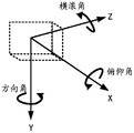
- the attitude angle data includes a pitch angle tilt, a direction angle pan, and a roll angle roll.
- Fig. 5 shows a schematic diagram of attitude angle data according to an embodiment of the present invention. The coordinate system shown in Figure 5 follows the right-hand rule, in which the pitch angle rotates around the X axis, the direction angle rotates around the Y axis, and the roll angle rotates around the Z axis.
- the method 300 also includes the step of calibrating the dynamic vision sensor 100 to determine the calibration parameters of the dynamic vision sensor.
- the dynamic vision sensor is calibrated with camera parameters to determine the center pixel position and focal length parameters corresponding to the dynamic vision sensor.
- the dynamic vision sensor must be calibrated with an inertial measurement unit to determine the inertial calibration parameters.
- the errors of inertial measurement units include axis quadrature deviation errors, scale scaling errors, and offsets. The existence of these errors will cause errors in the calculation of attitude angles and heading angles. Therefore, the inertial measurement unit needs to be calibrated.
- the coordinate system of the inertial measurement unit is based on the camera coordinate system, and the IMU is rotated in multiple directions to obtain data, and multiple sets of data are used to perform least squares solution to obtain the value of each inertial calibration parameter.
- the calibration of the accelerometer and the magnetometer is mainly realized by ellipsoid fitting.
- the calibration of the gyroscope is the average value of the data after long-term standing and thermal equilibrium. The orthogonal deviation error and scale scaling error of the gyroscope are ignored in this calibration.
- the calibration method of the inertial measurement unit we will not do too much expansion here. Any calibration method for camera parameters and IMU parameters can be combined with the embodiments of the present invention.
- calibration includes rotation parameters (6), scale parameters (3, Temporarily set as 1) and offset (3) with a total of 12 parameters, as shown in Table 3.
- the corresponding groups of inertial measurement parameters are determined respectively.
- Attitude angle data. Specifically, the attitude angle data corresponding to each group of inertial measurement parameters are calculated through the following steps.
- Fig. 6 shows a schematic flow chart of determining attitude angle data according to an embodiment of the present invention. It should be pointed out that after obtaining multiple sets of inertial measurement parameters corresponding to the first duration, for each set of inertial measurement parameters, the following steps are performed to determine the attitude angle data corresponding to the set of inertial measurement parameters.
- the first step is to use the calibration parameters of the dynamic vision sensor to process the acquired inertial measurement parameters to obtain the processed inertial measurement parameters.
- the calibration parameters of the dynamic vision sensor include: the calibration parameters of the gyroscope, the calibration parameters of the accelerometer, and the calibration parameters of the magnetometer.
- the three-axis data of the gyroscope (denoted as (gx,gy,gz)), the three-axis data of the accelerometer (denoted as (ax,ay,az)), and the three-axis data of the magnetometer (denoted by (mx,my,mz)) is processed to obtain the processed inertial measurement parameters, including: processed gyroscope three-axis data (denoted as (gx',gy',gz')), processed accelerometer three Axis data (denoted as (ax',ay',az')), processed magnetometer three-axis data (denoted as (mx',my',mz')).
- the second step is to process the processed gyroscope three-axis data using time difference integration to generate gyroscope attitude angle (denoted as (g_tilt, g_pan, g_roll)).
- the following formula is used to indicate that the time difference integral is used to calculate the gyroscope attitude angle:
- g_tilt k+1 g_tilt k + ⁇ t ⁇ gx′
- g_pan k+1 g_pan k + ⁇ t ⁇ gy′
- g_roll k+1 g_roll k + ⁇ t ⁇ gz′
- the third step is to use trigonometric functions to process the processed accelerometer three-axis data and the processed magnetometer three-axis data distribution to generate accelerometer attitude angle (denoted as (a_tilt, a_roll)) and magnetometer attitude respectively Angle (denoted as m_pan).
- the following formula is used to indicate that a trigonometric function is used to calculate the accelerometer attitude angle:
- Hx -mz′ ⁇ cos(a_tilt)+mx′ ⁇ sin(a_tilt)
- Hy my′ ⁇ cos(a_roll)-mz′ ⁇ sin(a_roll) ⁇ sin(a_tilt)-mx′ ⁇ cos(a_tilt) ⁇ sin(a_roll)
- the fourth step is to process the gyroscope attitude angle, accelerometer attitude angle, and magnetometer attitude angle based on complementary filtering to generate the final attitude angle.
- the gyro attitude angle and the accelerometer attitude angle are subjected to complementary filtering processing to generate tilt and roll; the gyro attitude angle and the magnetometer attitude angle are subjected to complementary filtering processing to generate pan, which can be obtained by the following formula Means:
- pan k 2 ⁇ g_pan+(1-k 2 ) ⁇ m_pan
- step S330 a transformation matrix is generated based on the determined posture angle data.
- the transformation matrix is generated in the following manner. First, calculate the difference of the attitude angle data corresponding to each group of inertial measurement parameters to obtain at least one attitude angle difference. Then, based on the calculated at least one attitude angle difference, at least one transformation matrix is generated. It should be noted that the difference of the attitude angle data can be recorded as:
- tilt i , pan i , roll i and tilt j , pan j , roll j respectively represent the attitude angle data corresponding to the two sets of inertial measurement parameters.
- attitude angle data corresponding to a set of inertial measurement parameters is abbreviated as P in the following, then the above formula can be abbreviated as
- the process of calculating the attitude angle difference can be simply summarized as: respectively calculating the attitude angle data of the other groups of inertial measurement parameters and the attitude angle of the first group of inertial measurement parameters in the time period corresponding to the first time period.
- the difference of the data The following continues to take FIGS. 4A to 4C as an example to describe in detail the process of calculating the attitude angle difference.
- the first time length is 10ms.
- the t0-t1 time period does not need to be further divided into sub-time periods, and the attitude angle data (denoted as P1) and t0 corresponding to time t1 are directly calculated.
- the difference of the attitude angle data (denoted as P0) corresponding to the time is denoted as P1-P0.
- the difference between the attitude angle P2 at time t2 and the attitude angle P1 at time t1 is calculated, which is recorded as P2-P1.
- the first time length is 30ms.
- the t0-t3 time period is divided into t0-t1 sub-time periods, t1-t2 sub-time periods, and t2-t3 sub-time periods .
- the first time length is 25ms.
- the t0-t' time period is divided into t0-t1 sub-time periods, t1-t2 sub-time periods, and t2-t' sub-time periods. period.
- At least one transformation matrix is correspondingly generated according to the at least one attitude angle difference value.
- the time period based on the output frequency of the inertial measurement parameter, the time period is divided into M sub-time periods, and the difference of the attitude angle data corresponding to each sub-time period is calculated, Obtain M attitude angle differences, and then based on the attitude angle differences, correspondingly generate each transformation matrix, a total of M transformation matrices.
- the transformation matrix is generated according to the following formula:
- ⁇ roll, ⁇ pan, and ⁇ tilt are attitude angle differences (that is, three quantities of ⁇ P), and cx, cy, and f respectively represent the position of the center pixel of the image and the focal length.
- step S340 this segment of the event data stream is processed using the transformation matrix to generate a processed event data stream.
- At least one transformation matrix in the corresponding period of the first duration is used to process the event data in the corresponding sub-period to finally generate a processed event data stream.
- using the generated at least one transformation matrix to process the event data stream is to separately process the position of at least one event data in the event data stream to generate the position of the processed event data.
- each event data is processed by the following formula:
- x_compensated warpMatrix(0,0) ⁇ x+warpMatrix(0,1) ⁇ y+warpMatrix(0,2)
- y_compensated warpMatrix(1,0) ⁇ x+warpMatrix(1,1) ⁇ y+warpMatrix(1,2)
- x and y are the locations of the original event data
- x_compensated and y_compensated are the locations of the processed event data.
- the method further includes the step of: using the generated processed event data stream to generate an image containing motion information.
- a frame of image is generated by mapping.
- the pixel information of the pixels in the image can represent the coordinate position of the event data (that is, the pixel unit that changes in brightness) and the sequence of triggering.
- the method of generating an image using the event data stream it will not be repeated here, and any known or future known method can be combined with the embodiment of the present invention.
- the attitude angle data is calculated through the acquired inertial measurement parameters, and the attitude angle data is used to process the event data output by the dynamic vision sensor, that is, the movement performed on the original event data Compensation can effectively reduce the tailing phenomenon, keep the image clear and sharp edges. This is extremely valuable for subsequent slam algorithm development and target detection algorithm development.
- FIG. 7A it is the optical flow image before processing, that is, the optical flow image generated by the event data stream before processing. It can be seen that when the dynamic vision sensor moves, some edges will have serious tailing phenomenon.
- Fig. 7B is the processed optical flow image, that is, the optical flow image generated by the event data stream processed by the method 300. It can be seen that the tailing phenomenon has been significantly improved, and the edge contour has become clearer and sharper.
- the present disclosure proposes a DVS native point cloud motion compensation scheme based on IMU pose fusion.
- the scheme uses the characteristics of the dynamic vision sensor to output asynchronous event data streams and directly outputs IMU motion compensation is performed on the event data.
- the algorithm is simple and effective, and does not rely on target depth estimation, so it will not cause serious time-consuming.
- the processing effect is more real-time. It can perform IMU compensation on a finer time segment to solve the problem of image smearing caused by DVS motion.
- modules or units or components of the device in the example disclosed herein can be arranged in the device as described in this embodiment, or alternatively can be positioned differently from the device in this example In one or more devices.
- the modules in the foregoing examples can be combined into one module or further divided into multiple sub-modules.
- modules or units or components in the embodiments can be combined into one module or unit or component, and in addition, they can be divided into multiple sub-modules or sub-units or sub-components. Except that at least some of such features and/or processes or units are mutually exclusive, any combination can be used to compare all features disclosed in this specification (including the accompanying claims, abstract and drawings) and any method or methods disclosed in this manner or All the processes or units of the equipment are combined. Unless expressly stated otherwise, each feature disclosed in this specification (including the accompanying claims, abstract and drawings) may be replaced by an alternative feature providing the same, equivalent or similar purpose.
Landscapes
- Engineering & Computer Science (AREA)
- Radar, Positioning & Navigation (AREA)
- Remote Sensing (AREA)
- Physics & Mathematics (AREA)
- General Physics & Mathematics (AREA)
- Manufacturing & Machinery (AREA)
- Multimedia (AREA)
- Signal Processing (AREA)
- Computer Vision & Pattern Recognition (AREA)
- Theoretical Computer Science (AREA)
- Automation & Control Theory (AREA)
- Gyroscopes (AREA)
- Image Processing (AREA)
Priority Applications (2)
| Application Number | Priority Date | Filing Date | Title |
|---|---|---|---|
| EP19934331.0A EP3988902A4 (de) | 2019-06-21 | 2019-06-27 | Verfahren zur verarbeitung von ereignisdatenströmen und computervorrichtung |
| US17/555,800 US12046007B2 (en) | 2019-06-21 | 2021-12-20 | Method for processing event data flow and computing device |
Applications Claiming Priority (2)
| Application Number | Priority Date | Filing Date | Title |
|---|---|---|---|
| CN201910542348.6A CN110296717B (zh) | 2019-06-21 | 2019-06-21 | 一种事件数据流的处理方法及计算设备 |
| CN201910542348.6 | 2019-06-21 |
Related Child Applications (1)
| Application Number | Title | Priority Date | Filing Date |
|---|---|---|---|
| US17/555,800 Continuation US12046007B2 (en) | 2019-06-21 | 2021-12-20 | Method for processing event data flow and computing device |
Publications (1)
| Publication Number | Publication Date |
|---|---|
| WO2020252806A1 true WO2020252806A1 (zh) | 2020-12-24 |
Family
ID=68028490
Family Applications (1)
| Application Number | Title | Priority Date | Filing Date |
|---|---|---|---|
| PCT/CN2019/093215 Ceased WO2020252806A1 (zh) | 2019-06-21 | 2019-06-27 | 一种事件数据流的处理方法及计算设备 |
Country Status (4)
| Country | Link |
|---|---|
| US (1) | US12046007B2 (de) |
| EP (1) | EP3988902A4 (de) |
| CN (1) | CN110296717B (de) |
| WO (1) | WO2020252806A1 (de) |
Families Citing this family (9)
| Publication number | Priority date | Publication date | Assignee | Title |
|---|---|---|---|---|
| CN111060138B (zh) * | 2019-12-31 | 2022-01-28 | 上海商汤智能科技有限公司 | 标定方法及装置、处理器、电子设备、存储介质 |
| CN112312017B (zh) * | 2020-10-29 | 2022-04-12 | 维沃移动通信有限公司 | 拍摄控制方法和电子设备 |
| CN112333390B (zh) * | 2020-10-29 | 2022-02-22 | 维沃移动通信有限公司 | 摄像头模组、摄像头模组的控制方法、装置及电子设备 |
| CN112577518A (zh) * | 2020-11-19 | 2021-03-30 | 北京华捷艾米科技有限公司 | 一种惯性测量单元标定方法及装置 |
| CN112989925B (zh) * | 2021-02-02 | 2022-06-10 | 豪威芯仑传感器(上海)有限公司 | 一种识别手部滑动方向的方法及系统 |
| JP7766115B2 (ja) * | 2022-01-28 | 2025-11-07 | 株式会社ソニー・インタラクティブエンタテインメント | 電子機器、情報処理方法およびプログラム |
| CN115242952B (zh) * | 2022-07-28 | 2024-07-26 | 联想(北京)有限公司 | 一种图像获取方法及装置 |
| CN115209055B (zh) * | 2022-07-29 | 2024-11-22 | 维沃移动通信有限公司 | 拍摄方法、装置、电子设备及可读存储介质 |
| CN119377561B (zh) * | 2024-09-20 | 2025-11-21 | 南京理工大学 | 基于事件星敏感器的动态自适应太阳逆光干扰消除方法 |
Citations (3)
| Publication number | Priority date | Publication date | Assignee | Title |
|---|---|---|---|---|
| CN107018357A (zh) * | 2016-01-27 | 2017-08-04 | 三星电子株式会社 | 关于图像形成的动态视觉传感器的事件采样的方法和设备 |
| CN108827299A (zh) * | 2018-03-29 | 2018-11-16 | 南京航空航天大学 | 一种基于改进四元数二阶互补滤波的飞行器姿态解算方法 |
| US20190096081A1 (en) * | 2017-09-28 | 2019-03-28 | Samsung Electronics Co., Ltd. | Camera pose determination and tracking |
Family Cites Families (8)
| Publication number | Priority date | Publication date | Assignee | Title |
|---|---|---|---|---|
| US10602927B2 (en) * | 2013-01-25 | 2020-03-31 | Wesley W. O. Krueger | Ocular-performance-based head impact measurement using a faceguard |
| US10110913B2 (en) * | 2016-09-30 | 2018-10-23 | Intel Corporation | Motion estimation using hybrid video imaging system |
| US10510160B2 (en) * | 2016-12-20 | 2019-12-17 | Samsung Electronics Co., Ltd. | Multiscale weighted matching and sensor fusion for dynamic vision sensor tracking |
| EP3451288A1 (de) * | 2017-09-04 | 2019-03-06 | Universität Zürich | Visuelle-inertiale odometrie mit einer ereigniskamera |
| US10529074B2 (en) * | 2017-09-28 | 2020-01-07 | Samsung Electronics Co., Ltd. | Camera pose and plane estimation using active markers and a dynamic vision sensor |
| CN108764078B (zh) * | 2018-05-15 | 2019-08-02 | 上海芯仑光电科技有限公司 | 一种事件数据流的处理方法及计算设备 |
| US10812711B2 (en) * | 2018-05-18 | 2020-10-20 | Samsung Electronics Co., Ltd. | Semantic mapping for low-power augmented reality using dynamic vision sensor |
| SG11202010898TA (en) * | 2018-05-22 | 2020-12-30 | Celepixel Tech Co Ltd | Optical flow calculation method and computing device |
-
2019
- 2019-06-21 CN CN201910542348.6A patent/CN110296717B/zh active Active
- 2019-06-27 WO PCT/CN2019/093215 patent/WO2020252806A1/zh not_active Ceased
- 2019-06-27 EP EP19934331.0A patent/EP3988902A4/de not_active Ceased
-
2021
- 2021-12-20 US US17/555,800 patent/US12046007B2/en active Active
Patent Citations (3)
| Publication number | Priority date | Publication date | Assignee | Title |
|---|---|---|---|---|
| CN107018357A (zh) * | 2016-01-27 | 2017-08-04 | 三星电子株式会社 | 关于图像形成的动态视觉传感器的事件采样的方法和设备 |
| US20190096081A1 (en) * | 2017-09-28 | 2019-03-28 | Samsung Electronics Co., Ltd. | Camera pose determination and tracking |
| CN108827299A (zh) * | 2018-03-29 | 2018-11-16 | 南京航空航天大学 | 一种基于改进四元数二阶互补滤波的飞行器姿态解算方法 |
Non-Patent Citations (1)
| Title |
|---|
| See also references of EP3988902A4 * |
Also Published As
| Publication number | Publication date |
|---|---|
| US12046007B2 (en) | 2024-07-23 |
| US20220114757A1 (en) | 2022-04-14 |
| CN110296717A (zh) | 2019-10-01 |
| EP3988902A4 (de) | 2022-08-10 |
| CN110296717B (zh) | 2020-08-28 |
| EP3988902A1 (de) | 2022-04-27 |
Similar Documents
| Publication | Publication Date | Title |
|---|---|---|
| US12046007B2 (en) | Method for processing event data flow and computing device | |
| US12425559B2 (en) | Online compensation of thermal distortions in a stereo depth camera | |
| CN102162738B (zh) | 摄像头与惯性传感器组合定位定姿系统的标定方法 | |
| US10915993B2 (en) | Display apparatus and image processing method thereof | |
| EP3786895B1 (de) | Verfahren, vorrichtung und einrichtung zur neupositionierung in einem kameraausrichtungsverfolgungsverfahren und speichermedium | |
| US10726580B2 (en) | Method and device for calibration | |
| WO2020199906A1 (zh) | 人脸关键点检测方法、装置、设备及存储介质 | |
| KR20200005332A (ko) | 캘리브레이션 장치 및 그것의 동작 방법 | |
| CN107560637B (zh) | 头戴显示设备校准结果验证方法及头戴显示设备 | |
| CN110660034B (zh) | 图像校正方法、装置及电子设备 | |
| TW201724031A (zh) | 擴增實境方法、系統及電腦可讀取非暫態儲存媒介 | |
| CN105981369A (zh) | 用于以数字图像格式向应用处理器提供传感器数据和图像数据的方法和系统 | |
| WO2022022141A1 (zh) | 图像显示方法、装置、计算机设备及存储介质 | |
| WO2020014813A1 (zh) | 计算对象和车辆碰撞时间的方法、计算设备及车辆 | |
| KR20220035250A (ko) | 공동 환경 재구성 및 카메라 교정 | |
| CN106249870A (zh) | 无源磁性头部跟踪器 | |
| CN107464266A (zh) | 摄像机标定参数的校正方法、装置、设备和存储介质 | |
| US9921054B2 (en) | Shooting method for three dimensional modeling and electronic device supporting the same | |
| WO2019222911A1 (zh) | 一种光流计算方法及计算设备 | |
| CN109906471A (zh) | 实时三维相机校准 | |
| CN105653017A (zh) | 电子装置及电子装置的重力感测校正方法 | |
| CN110660087B (zh) | 光感校正方法、装置、电子设备和存储介质 | |
| CN120071420A (zh) | 数据采集方法、装置、系统、电子设备、可读存储介质 | |
| KR20190051571A (ko) | 차량 주변 모니터링 장치 및 그의 영상 보정 방법 | |
| CN115023589B (zh) | 用于vislam应用的imu静态噪声校准缩放调整 |
Legal Events
| Date | Code | Title | Description |
|---|---|---|---|
| 121 | Ep: the epo has been informed by wipo that ep was designated in this application |
Ref document number: 19934331 Country of ref document: EP Kind code of ref document: A1 |
|
| NENP | Non-entry into the national phase |
Ref country code: DE |
|
| WWE | Wipo information: entry into national phase |
Ref document number: 2019934331 Country of ref document: EP |
|
| WWW | Wipo information: withdrawn in national office |
Ref document number: 2019934331 Country of ref document: EP |