WO2020254848A1 - Dispositif de transmission de puissance - Google Patents
Dispositif de transmission de puissance Download PDFInfo
- Publication number
- WO2020254848A1 WO2020254848A1 PCT/IB2019/000638 IB2019000638W WO2020254848A1 WO 2020254848 A1 WO2020254848 A1 WO 2020254848A1 IB 2019000638 W IB2019000638 W IB 2019000638W WO 2020254848 A1 WO2020254848 A1 WO 2020254848A1
- Authority
- WO
- WIPO (PCT)
- Prior art keywords
- pinion
- power transmission
- transmission device
- gear
- carrier
- Prior art date
- Legal status (The legal status is an assumption and is not a legal conclusion. Google has not performed a legal analysis and makes no representation as to the accuracy of the status listed.)
- Ceased
Links
Images


Classifications
-
- F—MECHANICAL ENGINEERING; LIGHTING; HEATING; WEAPONS; BLASTING
- F16—ENGINEERING ELEMENTS AND UNITS; GENERAL MEASURES FOR PRODUCING AND MAINTAINING EFFECTIVE FUNCTIONING OF MACHINES OR INSTALLATIONS; THERMAL INSULATION IN GENERAL
- F16H—GEARING
- F16H57/00—General details of gearing
- F16H57/02—Gearboxes; Mounting gearing therein
-
- F—MECHANICAL ENGINEERING; LIGHTING; HEATING; WEAPONS; BLASTING
- F16—ENGINEERING ELEMENTS AND UNITS; GENERAL MEASURES FOR PRODUCING AND MAINTAINING EFFECTIVE FUNCTIONING OF MACHINES OR INSTALLATIONS; THERMAL INSULATION IN GENERAL
- F16H—GEARING
- F16H57/00—General details of gearing
- F16H57/04—Features relating to lubrication or cooling or heating
Definitions
- the present invention relates to a power transmission device.
- a power transmission device composed of a planetary gear mechanism as a deceleration mechanism and a differential mechanism housed in a planetary carrier of the planetary gear mechanism is known.
- JP2002-295647A discloses a final speed reducing device in which a notch is provided on the back surface of a ring gear attached to a differential case, and lubricating oil is scraped up when the ring gear rotates.
- this final reduction gear one end is connected to the notch, and the other end is provided in the differential case with an introduction path that conducts to the meshing part between the pinion mate gear and the side gear, and the scraped lubricating oil is discharged from the notch. It is introduced inside the differential mechanism via the introduction path.
- An object of the present invention is to provide a power transmission device with reduced friction loss in view of the above problems.
- a tubular planetary carrier rotatably provided, a plurality of planetary pinion gears rotatably provided with respect to the planetary carrier and arranged around the rotation axis of the planetary carrier, and the inside of the planetary carrier.
- a power transmission device including a sun gear that meshes with a planetary pinion gear, an internal gear that meshes with a planetary pinion gear from the outside of the planetary carrier, and a differential mechanism housed in a gear accommodation chamber provided in the planetary carrier is provided.
- the planetary carrier includes an opening in the side wall of the carrier for accommodating the planetary pinion gear, and a pillar portion located between the adjacent planetary pinion gears and forming a part of the side wall of the carrier. Further, the planetary carrier is provided with an introduction path in the pillar portion for introducing the lubricating oil scraped up by the planetary pinion gear into the differential mechanism.
- FIG. 1 is a schematic configuration diagram of a power transmission device according to the first embodiment.
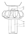
- FIG. 2 is a perspective view of the planet carrier in a state where the planet pinion gear and the differential mechanism are housed.
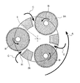
- FIG. 3 is a schematic configuration diagram of a power transmission device in a state where oil is injected.
- FIG. 4 is a side view of the planetary carrier.
- FIG. 5 is a cross-sectional view taken along the line II of FIG.
- FIG. 6 is a cross-sectional view taken along the line II-II of FIG.
- FIG. 7 is a cylindrical cross-sectional view of the planetary carrier.
- FIG. 8 is a top view of the planetary carrier with the cover member removed.
- FIG. 9 is a perspective view of the planetary carrier with the cover member removed.
- FIG. 8 is a top view of the planetary carrier with the cover member removed.
- FIG. 10 is a top view of the pinion mate shaft and the pinion mate gear.
- FIG. 11 is a top view of the pinion mate shaft and the pinion mate gear in the power transmission device according to the second embodiment.
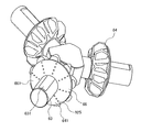
- FIG. 12 is a perspective view of the pinion mate shaft and the pinion mate gear in the power transmission device according to the third embodiment.
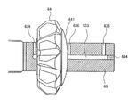
- FIG. 13 is a partial cross-sectional view of the pinion mate shaft and the pinion mate gear in the power transmission device according to the fourth embodiment as viewed from above.
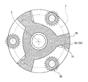
- FIG. 1 is a schematic configuration diagram of the power transmission device 100 according to the first embodiment.
- the power transmission device 100 includes a planetary gear mechanism 1 as a speed reduction mechanism, a differential mechanism 6 housed in the planetary carrier 2 of the planetary gear mechanism 1, and a casing 7 containing the planetary gear mechanism 1 and the differential mechanism 6. It is composed.
- the planetary gear mechanism 1 is, for example, a deceleration mechanism for decelerating the rotation of an electric motor that drives a vehicle.
- the planetary gear mechanism 1 includes a planet carrier 2, a planet pinion gear 3, a sun gear 4, and an internal gear 5, and is housed in a casing 7.
- the planet carrier 2 is a member that supports the planet pinion gear 3, is formed in a tubular shape, and is rotatably provided with respect to the casing 7. Protruding portions 21A and 21B protruding outward in the rotation axis direction of the planet carrier 2 are provided at both ends of the planet carrier 2 in the rotation axis direction.
- the planetary carriers 2 are rotatably supported by the casing 7 by supporting the projecting portions 21A and 21B by the ball bearings 71A and 71B as bearings fixed to the casing 7.
- the planet carrier 2 has an opening 22 (see FIG. 2) for accommodating the planet pinion gear 3 on the side wall of the carrier, and the accommodated planet pinion gear 3 is accommodated in the first support portion 23A and the second support portion 23B from the rotation axis direction of the planet pinion gear 3. Support by. Further, the planet carrier 2 has a gear accommodating chamber 24 for accommodating the differential mechanism 6 inside.
- the planetary pinion gear 3 is a stepped pinion gear in which a large-diameter pinion 3A and a small-diameter pinion 3B are integrally formed, and a plurality of planetary pinion gears 3 are arranged at equal intervals around the rotation axis of the planetary carrier 2 and are provided so as to be rotatable.
- the large-diameter pinion 3A and the small-diameter pinion 3B are arranged concentrically, and the pinion shaft 31 penetrates their central axes. Both ends of the pinion shaft 31 are supported by the first support portion 23A and the second support portion 23B of the planet carrier 2, respectively.
- the large-diameter pinion 3A meshes with the sun gear 4 inside the planet carrier 2, and the small-diameter pinion 3B meshes with the internal gear 5 outside the planet carrier 2.
- the planet pinion gear 3 a part of the outer circumference of the large-diameter pinion 3A protrudes in the radial direction from the outer circumference of the planet carrier 2.
- the power transmission device 100 of the present embodiment includes three planet pinion gears 3, but the number of planet pinion gears 3 is not limited to this.
- the planetary pinion gear 3 is a stepped pinion gear composed of a large-diameter pinion 3A and a small-diameter pinion 3B, but the planetary pinion gear 3 does not necessarily have to be a stepped pinion gear.
- the sun gear 4 is a member to which a driving force is input, and meshes with the large-diameter pinion 3A of the planet pinion gear 3 from the inside of the planet carrier 2.
- the rotor shaft 10 of the electric motor is fixed to the sun gear 4 by press fitting.
- the internal gear 5 is a gear that meshes with the small-diameter pinion 3B from the outside of the planet carrier 2, and is fixedly arranged on the inner wall of the casing 7.
- the internal gear 5 is provided in an annular shape along the inner wall of the casing 7.
- the differential mechanism 6 is a differential device for distributing the output of the planetary gear mechanism 1 (deceleration mechanism) to the left and right wheels of the vehicle, and is a space inside the small diameter pinion 3B in the planetary carrier 2 and is a cover portion. It is accommodated in a space (gear accommodating chamber 24) defined by 25 and a partition wall 61.
- the differential mechanism 6 includes a plurality of (for example, three) pinion mate shafts 63 supported by the planetary carrier 2, a plurality of (for example, three) pinion mate gears 64 supported by the pinion mate shaft 63, and a pinion mate gear 64. It is provided with a pair of side gears 65A and 65B that mesh with each other.
- the first output shaft 8A is fixed to the side gear 65A
- the second output shaft 8B is fixed to the side gear 65B.
- Wheels and the like are connected to the first output shaft 8A and the second output shaft 8B, respectively. Therefore, in the power transmission device 100, the output shafts 8A and 8B and the rotor shaft 10 of the electric motor are arranged coaxially. Therefore, the rotor shaft 10 is configured as a hollow tube, and the first output shaft 8A is provided so as to penetrate the inside of the rotor shaft 10.
- the driving force input to the sun gear 4 is output via the planet pinion gear 3 and the differential mechanism 6 and transmitted to the wheels. Further, when there is a difference in the rotational speeds of the two wheels, the difference is absorbed by the differential mechanism 6.
- FIG. 2 is a perspective view of the planet carrier 2 in a state where the planet pinion gear 3 and the differential mechanism 6 are housed.
- the planet carrier 2 is formed in a tubular shape, and the first support portion 23A constituting the bottom portion, the side wall having the opening portion 22, and the opening portion 22 are formed into the first opening portion 22A and the second opening portion 22B. It includes a second support portion 23B to be defined and a cover portion 25 that covers one end surface of the planet carrier 2.
- the planet pinion gear 3 is housed in the first opening 22A.
- the first support portion 23A, the side wall, and the second support portion 23B are integrally configured, and the cover member 251 is configured as a separate structure from these.
- the first support portion 23A constitutes the bottom portion of the planet carrier 2, and supports the planet pinion gear 3 housed in the first opening 22A from the large diameter pinion 3A side in the rotation axis direction of the planet carrier 2.
- a protruding portion 21A protruding outward in the rotation axis direction of the planet carrier 2 is provided on an end surface of the first supporting portion 23A on the side opposite to the surface supporting the planet pinion gear 3.
- the protrusion 21A is supported by the ball bearing 71A as a bearing in which the outer ring is fixed to the casing 7.
- the side wall of the planetary carrier 2 includes a plurality of (for example, three) pillar portions 26 and a plurality of (for example, three) openings 22.
- the opening 22 is defined by the second support 23B into a first opening 22A and a second opening 22B, and each of the first openings 22A accommodates a planetary pinion gear 3.
- the inside of the first opening 22A is such that a part of the back surface 32 of the large diameter pinion 3A is supported by the first support portion 23A and the upper surface 33 of the small diameter pinion 3B is supported by the second support portion 23B. Is located in.
- the first support portion 23A supports the planet pinion gear 3 from the large diameter pinion 3A side in the rotation axis direction of the planet carrier 2, and the second support portion 23B supports the planet pinion gear 3 from the small diameter pinion 3B in the rotation axis direction of the planet carrier 2. Support from the side.
- a partition wall 61 for forming a gear accommodating chamber 24 accommodating the differential mechanism 6 is formed at a position on the inner diameter side (closer to the central axis) of the small diameter pinion 3B in the planet carrier 2.
- the partition wall 61 is formed so as to circumscribe the inner surface of each pillar portion 26, and has a differential mechanism in a space (gear accommodating chamber 24) defined by the cover portion 25 forming one end surface of the planetary carrier 2 and the partition wall 61. 6 is housed.
- the pillar portion 26 forming a part of the side wall of the planet carrier 2 is located between the adjacent planet pinion gears 3, and is formed in a Y shape having a slit 261 and two leg portions 262 in a side view.
- the adjacent pillar portions 26 are connected to each other by the first support portion 23A and the second support portion 23B.
- the slit 261 of the pillar portion 26 constitutes a fitting portion 263 that holds the pinion mate shaft 63 of the differential mechanism 6.
- One end of the pillar portion 26 is connected to the first support portion 23A, and a stepped end face 264 is formed at the end portion on the side having the leg portion 262.
- the cover portion 25 is formed by placing the cover member 251 on the end surface 264.
- the cover member 251 is configured as a separate structure from the first support portion 23A, the side wall and the second support portion 23B, which are integrally formed. By forming the cover member 251 into a separate structure in this way, assembling property is ensured.
- the cover member 251 is provided with a cylindrical projecting portion 21B projecting outward in the rotation axis direction of the planetary carrier 2. As described above, the projecting portion 21B is supported by a ball bearing 71B as a bearing fixed to the casing 7. ing. Further, the cover member 251 has an extension portion 252 extending in the rotation axis direction of the planet carrier 2, and the extension portion 252 supports the pinion mate shaft 63 from a direction opposite to the fitting portion 263 of the pillar portion 26. That is, the pinion mate shaft 63 is supported in the slit 261 of the pillar portion 26 by the fitting portion 263 and the extension portion 252.
- FIG. 3 is a schematic configuration diagram of the power transmission device 100 in a state where oil (lubricating oil) is injected. Oil (lubricating oil) for lubricating each component of the power transmission device 100 is injected into the power transmission device 100.
- the amount of oil injected is such that a part of the planetary carrier 2 is immersed.
- the planet carrier 2 rotates, a portion of the large-diameter pinion 3A projecting radially outward from the planet carrier 2 hits the oil surface when entering the oil pool. As a result, the oil surface undulates, and then the oil is scraped up by the rotation of the large-diameter pinion 3A. The scraped oil is applied to the pillars 26 and the like of the planetary carrier 2.
- the amount of oil does not necessarily have to be such that a part of the planetary carrier 2 is immersed, and at least a part of the large diameter pinion 3A may be immersed when the large diameter pinion 3A is located at the lowermost position. ..
- the pillar portion 26 of the planetary carrier 2 is connected to a groove 91 for collecting the oil scooped up by the large-diameter pinion 3A and the groove 91.
- An introduction path 92 is provided, and the recovered oil is supplied from the introduction path 92 to the differential mechanism 6 inside the planetary carrier 2.
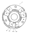
- FIG. 4 is a side view of the planetary carrier 2
- FIG. 5 is a cross-sectional view taken along the line II of FIG. 2
- FIG. 6 is a cross-sectional view taken along the line II-II of FIG.
- the arrow A in FIG. 5 indicates the rotation direction of the planetary carrier 2
- the arrow B indicates the rotation direction of the large-diameter pinion 3A
- the arrow C indicates the traveling direction of the oil.
- a groove 91 and an introduction hole 921 are formed in the pillar portion 26 of the planetary carrier 2.
- the groove 91 is an oil receiving portion that collects the oil scooped up by the large-diameter pinion 3A, and is formed in a concave shape on the side surface along the radial direction of the pillar portion 26 of the planet carrier 2, that is, the side surface facing the planet pinion gear 3. Further, the groove 91 is formed on the side surface of the planet carrier 2 along the radial direction of the pillar portion 26 on the side on which the oil splashes when the planet pinion gear 3 rotates and scoops up the oil when the vehicle moves forward. To. For example, when the planet pinion gear 3 rotates counterclockwise when the vehicle is moving forward, the oil splashes toward the left side surface of the pillar portion 26 in FIG. 5, so that the groove 91 is the left side surface of the side surfaces along the radial direction of the pillar portion 26. It is provided in.
- the groove 91 and the introduction hole 921 described later may be provided on both side surfaces of the pillar portion 26 along the two radial directions. As a result, the oil splashed when the vehicle is retracted can also be recovered by the groove 91.
- the introduction hole 921 constitutes a part of the introduction path 92 that supplies the oil recovered by the groove 91 to the differential mechanism 6 inside the planet carrier 2, and the introduction hole inlet 921A is located on the bottom surface of the groove 91.
- the introduction hole 921 is a hole for connecting the groove 91 and the space 922 formed in the fitting portion 263 of the pillar portion 26 described later.
- the oil recovered by the groove 91 is introduced from the introduction hole inlet 921A through the introduction hole 921 into the fitting portion 263 holding the pinion mate shaft 63.
- FIG. 7 is a cross-sectional view of the planet carrier 2 in the cylindrical direction, and is a view seen from the side surface of the planet carrier 2. As shown in FIG. 7, a space 922 is formed in the fitting portion 263 of the pillar portion 26.
- the space 922 constitutes a part of the introduction path 92 that supplies the oil recovered by the groove 91 to the differential mechanism 6 inside the planet carrier 2.
- the pinion mate shaft 63 has a flat surface portion 631 formed by cutting a part of the circumferential side surface of the pinion mate shaft 63, and the fitting portion 263 so that the flat surface portion 631 faces the slit 261. Will be installed in.
- a space 922 is formed between the flat surface portion 631 of the pinion mate shaft 63 and the pillar portion 26.
- the pinion mate shaft 63 is supported by the extension portion 252 of the cover portion 25 from the direction opposite to the fitting portion 263.
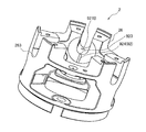
- FIG. 8 is a top view of the planet carrier 2 with the cover member 251 removed
- FIG. 9 is a perspective view of the planet carrier 2 with the cover member 251 removed.
- the fitting portion 263 of the pillar portion 26 is provided with an introduction hole outlet 921B which is an outlet of the introduction hole 921 at a position near the outer peripheral edge.
- the introduction hole outlet 921B is an outlet for leading the oil introduced into the introduction hole 921 from the groove 91 into the space 922.
- the introduction hole outlet 921B is preferably located on the outer peripheral side with respect to the rotation center of the planet carrier 2 with respect to the introduction hole inlet 921A. As a result, the oil in the introduction path 92 is easily discharged from the introduction hole outlet 921B by centrifugal force.
- a discharge port 923 is provided at the inner peripheral side end of the fitting portion 263, and a discharge port 923 of the fitting portion 263 is provided on the inner peripheral surface of the pillar portion 26.
- a discharge groove 924 which is a groove serving as an inlet, is provided.
- the discharge groove 924 is a groove for distributing the oil introduced into the space 922 into the differential mechanism 6, and constitutes a part of the introduction path 92.
- FIG. 10 is a top view of the pinion mate shaft 63 and the pinion mate gear 64.
- the pinion mate gear 64 is supported by the pinion mate shaft 63 at a position closer to the inner diameter of the pinion mate shaft 63.
- a flat surface portion 631 is provided at the central portion in the axial direction of the pinion mate shaft 63.
- the flat surface portion 631 is a position that includes the introduction hole outlet 921B when the pinion mate shaft 63 is installed in the fitting portion 263, and is in the inner diameter direction from a position that does not reach the outer diameter side end surface of the pinion mate shaft 63. Formed towards.
- the space 922 is formed so as to include the introduction hole outlet 921B and not reach the outside of the outer peripheral side surface of the planet carrier 2.
- the end (termination) of the flat surface portion 631 on the inner diameter direction side extends to a position where the pinion mate gear 64 is supported.
- the oil flowing into the space 922 from the introduction hole outlet 921B is transmitted through the pinion mate shaft 63, and is discharged from the discharge port 923 at a position where the pinion mate gear 64 is supported by the pinion mate shaft 63. It is discharged to 924.
- oil is introduced into the differential mechanism by an introduction path conducting to the meshing portion between the pinion mate gear and the side gear. Therefore, it is difficult to supply oil to a portion other than the meshing portion.
- the oil is discharged from the discharge port 923 at a position where the oil is transmitted through the pinion mate shaft 63 and the pinion mate gear 64 is supported. Therefore, the oil is distributed to the pinion mate shaft 63, the back surface portion 641 of the pinion mate gear 64, the sliding portion between the pinion mate shaft 63 and the pinion mate gear 64, the meshing portion of the pinion mate gear 64, and the like.
- the oil scooped up by the rotation of the large-diameter pinion 3A is collected by the groove 91, and enters the differential mechanism 6 through the introduction hole 921, the space 922, and the discharge groove 924 constituting the introduction path 92. Be supplied.
- the pillar portion 26 and the planet pinion gear 3 gradually become narrower as the distance between the side surface of the pillar portion 26 along the radial direction and the large diameter pinion 3A approaches the rotation center axis S of the planet carrier 2. It is configured and arranged so as to be. A part of the oil scraped up by the rotation of the large-diameter pinion 3A is collected in the groove 91, but a part of the oil is introduced into the planet carrier 2 from between the pillar portion 26 and the large-diameter pinion 3A.
- the distance between the side surface of the pillar 26 along the radial direction and the large-diameter pinion 3A gradually narrows as it approaches the rotation center axis S of the planetary carrier 2, that is, the planet from between the pillar 26 and the large-diameter pinion 3A.
- the cross-sectional area of the oil passage of the oil introduced into the carrier 2 gradually narrows with respect to the traveling direction of the oil (arrow C in FIG. 5).
- the dynamic pressure of the oil gradually increases with respect to the traveling direction of the oil, and the flow velocity of the oil increases. Therefore, the oil scraped up by the rotation of the large-diameter pinion 3A is efficiently distributed inside the planetary carrier 2. be able to. Therefore, oil can be efficiently supplied to the back surface portion and the meshing portion of the pinion mate gear 64 constituting the differential mechanism 6 housed inside the planetary carrier 2.
- the introduction hole 921 is provided at a position closer to the rotation center axis of the planetary carrier 2 in the pillar portion 26.
- the introduction hole 921 is provided at a position where the dynamic pressure of the oil is higher (a position closer to the rotation center axis S of the planetary carrier 2), the oil can be introduced efficiently through the introduction hole 921.
- the introduction hole 921 is provided at a position closer to the rotation center axis S of the planet carrier 2 than the circle T connecting the rotation centers of each pinion shaft 31 (planet pinion gear 3). Inside the circle T connecting the rotation centers of the pinion shafts 31, the distance between the side surface of the pillar 26 along the radial direction and the large-diameter pinion 3A is small, and more sufficient dynamic pressure of oil can be obtained. Further, it is more preferable that the introduction hole 921 is provided at a position where the distance between the side surface of the pillar portion 26 along the radial direction and the large-diameter pinion 3A is minimized. The highest dynamic pressure of oil can be obtained at this position.
- the introduction hole inlet 921A is preferably provided at a position in the height direction (cylindrical direction of the planetary carrier 2) closer to the large diameter pinion 3A side than the small diameter pinion 3B. By providing the introduction hole inlet 921A at a position close to the large-diameter pinion 3A that scrapes up the oil, the scraped up oil can be introduced into the introduction hole 921 more efficiently.
- the pinion mate shaft 63 is provided with the flat surface portion 631 to form the space 922, but the method for forming the space 922 is not limited to this.
- a concave groove may be provided in the fitting portion 263 of the pillar portion 26 to form a space, or the flat surface portion 631 of the pinion mate shaft 63 is provided and the pillar portion is provided.
- a groove may be provided in the portion 26 to form a space.
- the space 922 does not reach the outside of the outer peripheral side surface of the planetary carrier 2 by forming the flat surface portion 631 from a position that does not reach the outer diameter side end surface of the pinion mate shaft 63 toward the inner diameter direction.
- the space 922 may not reach the outside of the outer peripheral side surface of the planet carrier 2 by incorporating an oil seal between the introduction hole outlet 921B and the outer peripheral side surface of the planet carrier 2.
- the power transmission device 100 includes a tubular planetary carrier 2 that is rotatably provided, a plurality of planetary pinion gears 3 that are rotatably provided with respect to the planetary carrier 2 and are arranged around the rotation axis of the planetary carrier 2, and a planetary carrier 2.
- the differential mechanism 6 is accommodated in the gear accommodating chamber 24 provided in the vehicle.
- the planet carrier 2 includes an opening for accommodating the planet pinion gear 3 on the carrier side wall, and a pillar portion 26 located between the adjacent planet pinion gears 3 and forming a part of the carrier side wall.
- the planet carrier 2 is provided with an introduction path 92 for introducing the oil (lubricating oil) scraped up by the planet pinion gear 3 into the differential mechanism 6 in the pillar portion 26.
- the introduction path 92 for introducing the oil scooped up by the planet pinion gear 3 into the differential mechanism 6 is provided in the pillar portion 26, the oil scooped up without having to take an oil bath with reference to the differential mechanism 6.
- Oil can be introduced into the differential mechanism 6. That is, since the oil can be supplied to the differential mechanism 6 if only a part of the planet pinion gear 3 is bathed in oil, the lubricating oil can be introduced into the differential mechanism 6 while reducing the friction loss. Therefore, it is possible to provide a power transmission device with reduced friction loss.
- the lubricating oil can be introduced into the differential mechanism 6 only by scraping up the planet pinion gear 3, there is no need to install a forced lubrication device such as a pump. That is, since a pump or the like is not used, cost reduction and weight reduction are possible. Therefore, it is possible to provide a power transmission device with reduced friction loss while realizing cost reduction and weight reduction.
- the power transmission device 100 constitutes an introduction hole 921 (introduction hole entrance 921A) provided on a surface where one end (entrance) of the introduction path 92 faces the planet pinion gear 3 of the pillar portion 26. Since the entrance of the introduction path 92 is provided on the surface facing the planet pinion gear 3, the oil scooped up by the planet pinion gear 3 can be efficiently introduced into the differential mechanism 6.
- the power transmission device 100 includes a groove 91 in which the pillar portion 26 of the planetary carrier 2 is connected to the introduction path 92.
- the oil scooped up by the planet pinion gear 3 is applied to the pillar portion 26 of the planet carrier 2, but since the power transmission device 100 has a groove 91 in the pillar portion 26, the scooped up oil is efficiently collected by the groove 91. can do. As a result, oil can be efficiently supplied to each component constituting the differential mechanism 6 via the groove 91 and the introduction path 92.
- the power transmission device 100 configures the planet carrier 2 and the planet pinion gear 3 so that the distance between the pillar portion 26 of the planet carrier 2 and the planet pinion gear 3 becomes narrower as it approaches the rotation center axis S of the planet carrier 2.
- the structure is such that the flow path of the oil gradually narrows with respect to the direction in which the oil is scraped up, the dynamic pressure of the oil increases and the flow velocity of the oil increases.
- the oil scooped up by the planet pinion gear 3 can be efficiently distributed inside the planet carrier 2, and the oil is efficiently supplied to the back surface 641 and the meshing portion of the pinion mate gear 64 constituting the differential mechanism 6. can do.
- the power transmission device 100 is provided at a position where the introduction hole 921 (introduction hole inlet 921A) is closer to the rotation center axis S of the planet carrier 2 in the pillar portion 26 of the planet carrier 2. That is, the introduction hole 921 is provided at a position where the dynamic pressure of the oil is higher. Therefore, the oil supplied to the differential mechanism 6 can be introduced into the introduction hole 921 more efficiently.
- the power transmission device 100 has a fitting portion 263 in which the pillar portion 26 of the planetary carrier 2 holds the pinion mate shaft 63 of the differential mechanism 6, and the fitting portion 263 includes the pillar portion 26 and the pinion mate shaft 63. It has a space 922 through which oil (lubricating oil) passes between the two. Then, the introduction hole 921 conducts to the space 922 of the fitting portion 263. In this way, since the space 922 is formed between the pinion mate shaft 63 and the fitting portion 263 of the pillar portion 26, the oil scooped up by the planet pinion gear 3 is transmitted to the pinion mate shaft 63 and the fitting portion 263. It can be supplied to the differential mechanism 6. That is, since the oil is supplied to the pinion mate shaft 63 and the fitting portion 263, the oil also spreads to the pinion mate shaft 63 and the fitting portion 263, and the lubricity of the entire power transmission device 100 is improved.
- the space 922 between the pillar portion 26 and the pinion mate shaft 63 does not communicate with the outside of the outer peripheral side surface of the planet carrier 2. As described above, since the space 922 does not communicate with the outside of the outer peripheral side surface of the planet carrier 2, it is possible to prevent the oil supplied to the space 922 from leaking to the outside of the planet carrier 2.
- the fitting portion 263 of the pillar portion 26 discharges the oil (lubricating oil) introduced into the space 922 from the introduction hole 921 toward the differential mechanism 6 at the discharge port 923 (discharge groove 924). To be equipped. As a result, oil can be efficiently supplied to the differential mechanism 6.
- a groove 91 is provided in the pillar portion 26 of the planetary carrier 2 in order to efficiently recover the scraped oil, but the present invention is not limited to this, and the pillar portion 26 does not have a groove 91.
- the direct introduction path 92 may be provided.
- the power transmission device 100 according to the second embodiment will be described with reference to FIG.
- the same elements as those in the first embodiment are designated by the same reference numerals, and the description thereof will be omitted.
- FIG. 11 is a top view of the pinion mate shaft 63 and the pinion mate gear 64 in the power transmission device 100 according to the second embodiment.
- the present embodiment is different from the first embodiment in that the flat surface portion 631 of the pinion mate shaft 63 extends from the pinion mate gear 64 to the central axis side of the planet carrier 2.
- a flat surface portion 631 is formed in the center of the pinion mate shaft 63.
- the pinion mate shaft 63 is installed in the fitting portion 263 so that the flat surface portion 631 faces the slit 261.
- the flat surface portion 631 is formed in the inner diameter direction from a position that does not reach the outer diameter side end surface of the pinion mate shaft 63, and extends from the pinion mate gear 64 to the central axis side (inner diameter side) of the planet carrier 2. That is, the terminal 632 of the flat surface portion 631 is located on the inner diameter side of the pinion mate gear 64. Therefore, a space formed by the flat surface portion 631 is also formed between the pinion mate gear 64 and the pinion mate shaft 63.
- the space 922 formed between the pillar portion 26 and the pinion mate shaft 63 is connected to the space formed between the pinion mate gear 64 and the pinion mate shaft 63. Therefore, the oil that has flowed into the space 922 is transmitted through the pinion mate shaft 63, passes through the space (sliding portion) between the pinion mate gear 64 and the pinion mate shaft 63, and is discharged into the differential mechanism 6 at the terminal 632 of the flat surface portion 631. To. Further, a part of the oil transmitted through the pinion mate shaft 63 is supplied to the back surface portion 641 of the pinion mate gear 64 and the meshing portion of the pinion mate gear 64.
- the oil (lubricating oil) scooped up by the planetary pinion gear 3 is efficiently collected by the pinion mate shaft 63, the sliding portion between the pinion mate gear 64 and the pinion mate shaft 63, the back surface portion 641 of the pinion mate gear 64, and the meshing portion. Can be supplied to. Therefore, while reducing the friction loss, the scraped oil can be efficiently distributed by each component constituting the differential mechanism 6.
- the power transmission device 100 according to the third embodiment will be described with reference to FIG.
- the same elements as those in the first and second embodiments are designated by the same reference numerals, and the description thereof will be omitted.
- FIG. 12 is a perspective view of the pinion mate shaft 63 and the pinion mate gear 64 in the power transmission device 100 according to the third embodiment.
- the present embodiment is different from the other embodiments in that the washer 66 on the back surface portion 641 of the pinion mate gear 64 is provided with the discharge port 925.
- the plurality of pinion mate gears 64 have a disc-shaped washer 66 incorporated in the back surface portion 641, and the flat surface portion 631 of each pinion mate shaft 63 extends to the washer 66.
- Each washer 66 is provided with a plurality of outlets 925 arranged radially from the center of the washer 66.
- the discharge port 925 is a hole that connects the surface 661 of the washer 66 (the back surface portion 641 of the pinion mate gear 64) to the meshing portion of the pinion mate gear 64.
- a plurality of discharge ports 925 of the washer 66 are arranged radially from the center of the washer 66, but the present invention is not limited to this, and the discharge ports 925 may be arranged in any way.
- the power transmission device 100 is provided with an outlet 925 on the washer 66 on the back surface portion 641 of the pinion mate gear 64. Therefore, the oil that has flowed into the space 922 travels through the pinion mate shaft 63, reaches the washer 66, and flows into the meshing portion of the pinion mate gear 64 from the discharge port 925 of the washer 66. As a result, the scraped oil (lubricating oil) can be more efficiently supplied to the back surface portion 641 and the meshing portion of the pinion mate gear 64. Therefore, while reducing the friction loss, the scraped oil can be efficiently distributed by each component constituting the differential mechanism 6.
- the power transmission device 100 according to the fourth embodiment will be described with reference to FIG.
- the same elements as those of the other embodiments are designated by the same reference numerals, and the description thereof will be omitted.
- FIG. 13 is a partial cross-sectional view of the pinion mate shaft 63 and the pinion mate gear 64 in the power transmission device 100 according to the fourth embodiment as viewed from above.
- a space 633 as an oil passage is provided in the axial center portion (inside) of the pinion mate shaft 63, which is another embodiment. Different from.
- the space 633 is a hole provided in the axial center of the pinion mate shaft 63, is formed from the outer diameter side end face of the pinion mate shaft 63 toward the inner diameter, and is closer to the central axis side of the planetary carrier 2 than the pinion mate gear 64. It extends to (inner diameter side).
- the inner diameter side end of the space 633 is preferably located on the inner diameter side of the pinion mate gear 64, but is not necessarily limited to this, and may be formed so as to extend to the position of the pinion mate gear 64, for example.
- the portion leading to the outer diameter side end surface (outside the side surface of the planetary carrier 2) of the pinion mate shaft 63 of the space 633 is closed by the cap 634. This makes it possible to prevent oil from leaking from the outer diameter side end surface of the pinion mate shaft 63 when the oil passes through the space 633.
- the space 633 may be formed from a position that does not reach the outer diameter side end surface of the pinion mate shaft 63 toward the inner diameter direction.
- the pinion mate shaft 63 is provided with a hole 635 that conducts from the circumferential surface of the pinion mate shaft 63 to the space 633.
- the hole 635 is an oil passage for introducing oil (lubricating oil) from the introduction hole 921 into the space 633, one end of which is connected to the introduction hole outlet 921B, and the other end of which is conductive to the space 633.
- the pinion mate shaft 63 is provided with a discharge port 636 that conducts from the space 633 to the circumferential surface of the pinion mate shaft 63 at a position near the back surface portion 641 of the pinion mate gear 64 and the meshing portion of the pinion mate gear 64. Has been done.
- the discharge port 636 is provided near the back surface portion 641 of the pinion mate gear 64 and near the meshing portion of the pinion mate gear 64, but the present invention is not necessarily limited to this.
- the discharge port 636 can be arbitrarily provided at a desired location where lubricating oil is desired to be supplied.
- the power transmission device 100 is provided with a space 633 connected to the introduction hole 921 in the pinion mate shaft 63, and is provided with a discharge port 636 for discharging the oil (lubricating oil) introduced into the space 633 toward the differential mechanism 6. Since the discharge port 636 can be provided at a desired location where the lubricating oil is desired to be supplied, the oil can be efficiently supplied to the required location. As a result, the scraped oil can be efficiently supplied to each component constituting the differential mechanism 6.
Landscapes
- Engineering & Computer Science (AREA)
- General Engineering & Computer Science (AREA)
- Mechanical Engineering (AREA)
- General Details Of Gearings (AREA)
Abstract
L'invention concerne un dispositif de transmission de puissance comprenant : un porte-satellites cylindrique rotatif; des engrenages d'une pluralité d'engrenages à pignons planétaires qui sont individuellement disposés de façon à pouvoir tourner sur leur axe par rapport au porte-satellites et qui sont disposés autour de l'axe de rotation du porte-satellites; une roue solaire qui engrène avec les engrenages à pignons planétaires à partir de l'intérieur du porte-satellites; un engrenage interne qui engrène avec les engrenages à pignons planétaires depuis l'extérieur du porte-satellites; et un mécanisme différentiel qui est logé dans une chambre de réception d'engrenages qui est disposée dans le porte-satellites. Le porte-satellites est pourvu : d'ouvertures destinées à recevoir les engrenages à pignons planétaires dans la paroi latérale de support; et de parties de pilier qui sont situées entre des engrenages à pignons planétaires adjacents et qui forment une partie de la paroi latérale de support. Le porte-satellites est également pourvu, dans les parties de pilier, de trajets d'introduction permettant d'introduire de l'huile de lubrification brassée par les engrenages à pignons planétaires dans le mécanisme différentiel.
Priority Applications (1)
| Application Number | Priority Date | Filing Date | Title |
|---|---|---|---|
| PCT/IB2019/000638 WO2020254848A1 (fr) | 2019-06-21 | 2019-06-21 | Dispositif de transmission de puissance |
Applications Claiming Priority (1)
| Application Number | Priority Date | Filing Date | Title |
|---|---|---|---|
| PCT/IB2019/000638 WO2020254848A1 (fr) | 2019-06-21 | 2019-06-21 | Dispositif de transmission de puissance |
Publications (1)
| Publication Number | Publication Date |
|---|---|
| WO2020254848A1 true WO2020254848A1 (fr) | 2020-12-24 |
Family
ID=74040136
Family Applications (1)
| Application Number | Title | Priority Date | Filing Date |
|---|---|---|---|
| PCT/IB2019/000638 Ceased WO2020254848A1 (fr) | 2019-06-21 | 2019-06-21 | Dispositif de transmission de puissance |
Country Status (1)
| Country | Link |
|---|---|
| WO (1) | WO2020254848A1 (fr) |
Citations (4)
| Publication number | Priority date | Publication date | Assignee | Title |
|---|---|---|---|---|
| JPS55163364A (en) * | 1979-06-02 | 1980-12-19 | Nissan Diesel Motor Co Ltd | Lubricating device of differential reduction gear for vehicle |
| JP2007120518A (ja) * | 2005-10-25 | 2007-05-17 | Honda Motor Co Ltd | 車両の動力伝達装置 |
| JP2007120519A (ja) * | 2005-10-25 | 2007-05-17 | Honda Motor Co Ltd | 動力伝達装置の潤滑装置 |
| JP2018100717A (ja) * | 2016-12-20 | 2018-06-28 | 本田技研工業株式会社 | 動力装置 |
-
2019
- 2019-06-21 WO PCT/IB2019/000638 patent/WO2020254848A1/fr not_active Ceased
Patent Citations (4)
| Publication number | Priority date | Publication date | Assignee | Title |
|---|---|---|---|---|
| JPS55163364A (en) * | 1979-06-02 | 1980-12-19 | Nissan Diesel Motor Co Ltd | Lubricating device of differential reduction gear for vehicle |
| JP2007120518A (ja) * | 2005-10-25 | 2007-05-17 | Honda Motor Co Ltd | 車両の動力伝達装置 |
| JP2007120519A (ja) * | 2005-10-25 | 2007-05-17 | Honda Motor Co Ltd | 動力伝達装置の潤滑装置 |
| JP2018100717A (ja) * | 2016-12-20 | 2018-06-28 | 本田技研工業株式会社 | 動力装置 |
Similar Documents
| Publication | Publication Date | Title |
|---|---|---|
| CN111379844B (zh) | 用于轮毂电动机动力传动系统的润滑系统 | |
| JP6796421B2 (ja) | 潤滑油の供給構造 | |
| EP2735463B1 (fr) | Dispositif d'engrenage planétaire | |
| JP6551389B2 (ja) | ハイブリッド車両の潤滑構造 | |
| JP5496767B2 (ja) | 建設機械の旋回装置 | |
| JP6087008B2 (ja) | 車両用駆動装置 | |
| EP2821672A1 (fr) | Dispositif de commande d'un véhicule | |
| CN107614939B (zh) | 润滑装置 | |
| US7022039B2 (en) | Lubrication system for planetary transmission | |
| JP6105535B2 (ja) | ディファレンシャルギヤの潤滑構造 | |
| US9347541B2 (en) | Modular power transfer unit assembly for a vehicle | |
| SE441469B (sv) | Smorjanordning for en vexellada | |
| JP4610227B2 (ja) | 動力伝達装置の区画構造 | |
| EP3406943B1 (fr) | Ensemble essieu | |
| US4567784A (en) | Method and apparatus for lubricating a transmission | |
| JP2011122711A (ja) | 車両用動力伝達機構の潤滑装置 | |
| JP7392218B2 (ja) | 潤滑構造 | |
| JP2016191418A (ja) | 差動装置 | |
| JPH0681929A (ja) | 電気自動車用ドライブユニット | |
| JP4936947B2 (ja) | アクスル装置 | |
| JP6850226B2 (ja) | 動力装置 | |
| JP2012077848A (ja) | 複合遊星歯車装置の潤滑構造 | |
| EP3499087B1 (fr) | Dispositif à train planétaire | |
| WO2020254848A1 (fr) | Dispositif de transmission de puissance | |
| CN215410105U (zh) | 具有行星轮轴承润滑组件的齿轮箱 |
Legal Events
| Date | Code | Title | Description |
|---|---|---|---|
| 121 | Ep: the epo has been informed by wipo that ep was designated in this application |
Ref document number: 19933250 Country of ref document: EP Kind code of ref document: A1 |
|
| NENP | Non-entry into the national phase |
Ref country code: DE |
|
| 122 | Ep: pct application non-entry in european phase |
Ref document number: 19933250 Country of ref document: EP Kind code of ref document: A1 |
|
| NENP | Non-entry into the national phase |
Ref country code: JP |