WO2020255216A1 - Dispositif de conception de trajet de transmission, procédé de conception de topologie de réseau de transmission et programme de conception de trajet de transmission - Google Patents
Dispositif de conception de trajet de transmission, procédé de conception de topologie de réseau de transmission et programme de conception de trajet de transmission Download PDFInfo
- Publication number
- WO2020255216A1 WO2020255216A1 PCT/JP2019/023936 JP2019023936W WO2020255216A1 WO 2020255216 A1 WO2020255216 A1 WO 2020255216A1 JP 2019023936 W JP2019023936 W JP 2019023936W WO 2020255216 A1 WO2020255216 A1 WO 2020255216A1
- Authority
- WO
- WIPO (PCT)
- Prior art keywords
- communication path
- transmission network
- group
- communication
- bases
- Prior art date
- Legal status (The legal status is an assumption and is not a legal conclusion. Google has not performed a legal analysis and makes no representation as to the accuracy of the status listed.)
- Ceased
Links
Images


Classifications
-
- H—ELECTRICITY
- H04—ELECTRIC COMMUNICATION TECHNIQUE
- H04L—TRANSMISSION OF DIGITAL INFORMATION, e.g. TELEGRAPHIC COMMUNICATION
- H04L45/00—Routing or path finding of packets in data switching networks
- H04L45/12—Shortest path evaluation
- H04L45/126—Shortest path evaluation minimising geographical or physical path length
-
- H—ELECTRICITY
- H04—ELECTRIC COMMUNICATION TECHNIQUE
- H04L—TRANSMISSION OF DIGITAL INFORMATION, e.g. TELEGRAPHIC COMMUNICATION
- H04L12/00—Data switching networks
- H04L12/28—Data switching networks characterised by path configuration, e.g. LAN [Local Area Networks] or WAN [Wide Area Networks]
-
- H—ELECTRICITY
- H04—ELECTRIC COMMUNICATION TECHNIQUE
- H04L—TRANSMISSION OF DIGITAL INFORMATION, e.g. TELEGRAPHIC COMMUNICATION
- H04L45/00—Routing or path finding of packets in data switching networks
- H04L45/02—Topology update or discovery
-
- H—ELECTRICITY
- H04—ELECTRIC COMMUNICATION TECHNIQUE
- H04L—TRANSMISSION OF DIGITAL INFORMATION, e.g. TELEGRAPHIC COMMUNICATION
- H04L45/00—Routing or path finding of packets in data switching networks
- H04L45/24—Multipath
Definitions
- the present invention relates to a transmission line design device, a transmission network topology design method, and a transmission line design program that can be used for designing a regional transmission network or the like.
- Optical transmission networks used for regional transmission networks, etc. are required to reduce the operating costs of equipment and maintenance while maintaining high communication quality and availability as a common platform. Further, in a regional transmission network where efficient accommodation of user traffic is required, a multi-ring configuration that simply secures route redundancy by a two-way ROADM (Reconfigurable Optical Add / Drop Multiplexer) is common. However, maintaining high availability requires rapid recovery measures and a large-scale maintenance system.
- ROADM Reconfigurable Optical Add / Drop Multiplexer
- Non-Patent Document 1 the optical transmission network is configured as a mesh using a multi-way OXC (Optical Cross-connect), and a route for bypassing the failure location is set (restored) when a failure occurs, thereby performing a regional transmission network.
- OXC Optical Cross-connect
- Non-Patent Document 1 the number of communication paths (links) between buildings accommodating the communication equipment of each communication base is larger than in the case of the multi-ring configuration. Become. That is, if the mesh configuration is adopted, the amount of equipment such as an inter-station amplifier increases, and there is a concern that the operating cost of equipment and maintenance will increase.
- the present invention has been made in view of the above circumstances, and it is possible to easily design a channel topology optimized in consideration of suppressing the required amount of equipment under the condition of maintaining availability against multiple failures. It is an object of the present invention to provide a transmission line design device, a transmission network topology design method, and a transmission line design program.
- the transmission line design device of the present invention holds initial data of a transmission network model in which a plurality of bases adjacent to each other are connected by a communication path in a transmission network having a large number of bases and the whole is configured in a mesh shape.
- Initial data holding part and The initial data of the transmission network model held by the initial data holding unit is acquired, and the number of directions of the communication path connected to each base is larger than the specified value from among a large number of bases in the transmission network model.
- the bases of one group are extracted, the communication paths of the first group connecting the bases of the first group are extracted from each of the communication paths, and each of the communication paths of the first group is set at one end thereof.
- the connected first base and the second base connected to the other end are specified, and the number of directions of the communication path at the first base and the direction of the communication path at the second base are specified.
- the both-end route values are calculated according to the number, and among the communication paths of the first group, those whose both-end route values satisfy a predetermined condition are specified as the communication paths to be thinned out, and the initial stage of the transmission network model.
- a model calculation unit that generates output data that reflects the communication path to be thinned out for the data. It is characterized by including a data output unit that outputs the output data generated by the model calculation unit.
- the transmission network topology design method, the transmission line design program, and the transmission line design device of the present invention communication optimized in consideration of suppressing the required amount of equipment under the condition of maintaining availability against multiple failures.
- the road topology can be easily designed. That is, it is possible to automate the design of the communication path topology and support the design work of the designer.
- FIG. 1A shows an example of a configuration of a main part of a wide-area optical transmission network.
- FIG. 1B shows an example of communication equipment configuration in the regional representative building 16 in FIG. 1A.
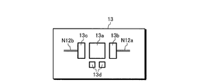
- FIG. 1C shows an example of communication equipment configuration in the regional building 13.
- the optical transmission network shown in FIG. 1A includes a regional transmission network 10, an access network 20, and a core transmission network 30.
- Optical communication equipment which is the base of the communication network, is housed in each building.
- the access network 20 connects each user terminal 21 existing in the house or the like with any of the regional buildings 11, 12, 13, 14 and provides a communication environment for each user.
- the regional transmission network 10 is a communication network connecting a plurality of buildings in an urban area or the like, that is, a metro network.
- the communication networks N11, N12, and N01 are included in the regional transmission network 10.
- the communication network N11 connects the regional representative buildings 15, the regional buildings 11, and 12 to each other via a ring-shaped optical fiber communication path.
- the communication network N12 connects the regional representative buildings 16, the regional buildings 13, and 14 to each other via a ring-shaped optical fiber communication path.
- the communication network N01 connects the prefecture representative buildings 17, 18 and the regional representative buildings 15, and 16 to each other via a ring-shaped optical fiber communication path.
- the communication network N11 and the communication network N01 are connected to each other via the regional representative building 15, and the communication network N12 and the communication network N01 are connected to each other via the regional representative building 16. It is connected. Further, the communication network N31 of the core transmission network 30 and the communication network N01 of the regional transmission network 10 are connected to each other via the prefecture representative building 17.
- the core transmission network 30 includes a plurality of core representative buildings 31.
- the communication network N31 connects the core representative building 31 and the prefecture representative building 17 via a ring-shaped optical fiber communication path.
- each communication facility connected to the ring-shaped communication paths is either clockwise or counterclockwise in the ring-shaped communication path. It is possible to communicate using the route of. As a result, resistance to obstacles such as disconnection can be provided.
- the regional representative building 16 is equipped with an optical switch (OXC) 16a, inter-station interfaces 16b and 16c, and a transponder (TPND) 16d as equipment on the communication network N01 side. Further, the regional representative building 16 is provided with an optical switch 16f, inter-station interfaces 16g, 16h, and a transponder 16e as equipment on the communication network N12 side.
- OXC optical switch
- TPND transponder
- the optical switch 16a is connected to one end N01a of the communication network N01 via the inter-station interface 16b, and is connected to the other end N01b of the communication network N01 via the inter-station interface 16c.
- the optical switch 16f is connected to one end N12a of the communication network N12 via the inter-station interface 16g, and is connected to the other end N12b of the communication network N12 via the inter-station interface 16h. Further, the transponder 16d and the transponder 16e are connected to each other.
- the regional building 13 shown in FIG. 1C is provided with an optical switch 13a, inter-station interfaces 13b and 13c, and a transponder 13d as equipment on the communication network N12 side.
- the optical switch 13a is connected to one end N12a of the communication network N12 via the inter-station interface 13b, and is connected to the other end N01b of the communication network N12 via the inter-station interface 13c.
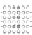
- FIG. 2 shows a configuration example of a model in which each base of the regional transmission network 10 is arranged at each position on the square grid.
- This model represents the numerous buildings at each communication site and the physical connections between them.
- the buildings B11 and B12 correspond to the prefecture representative buildings 17 and 18 in FIG. 1A
- the buildings B21, B22, B23 and B24 correspond to the regional representative buildings 15 and 16 in FIG. 1A. Equivalent to. Further, the buildings B311, B312, B315, B316, ... Not hatched in FIG. 2 correspond to the regional buildings 11, 12, 13, 14 in FIG. 1A.
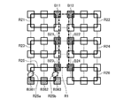
- FIG. 3 shows a model of a regional transmission network in which each communication path has a multi-ring configuration.
- ring communication is performed between the buildings B11 and B12 corresponding to the prefecture representative buildings 17 and 18 in FIG. 1A and the buildings B21 to B24 corresponding to the regional representative buildings 15 and 16 in FIG. 1A. They are connected to each other by the network R1.
- the ring communication networks R21, R22, R23, R24, R25, and R26 are connected to the buildings B11, B12, B21, B22, B23, and B24, respectively.
- the ring communication network R21 connects the building B11 and each regional building in the vicinity by a ring-shaped communication path.
- the ring communication network R22 connects the building B12 and each regional building in the vicinity by a ring-shaped communication path.
- the ring communication network R23 connects the building B21 and each regional building in the vicinity by a ring-shaped communication path.
- the ring communication network R24 connects the building B22 and each regional building in the vicinity by a ring-shaped communication path.
- the ring communication network R25 connects the building B23 and each regional building in the vicinity by a ring-shaped communication path.
- the ring communication network R26 connects the building B24 and each regional building in the vicinity by a ring-shaped communication path.
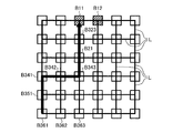
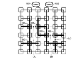
- FIGS. 4A and 4B A regional transmission network model in which each communication path has a mesh configuration is shown in FIGS. 4A and 4B. The route before the failure and the route after the failure are shown in FIGS. 4A and 4B, respectively.
- the buildings B11 and B12 corresponding to the prefecture representative buildings 17 and 18 in FIG. 1A and a large number of buildings corresponding to the regional buildings 11 to 14 in FIG. 1A are square. It is arranged at each position on the grid. Further, in the models of FIGS. 4A and 4B, the buildings arranged at positions adjacent to each other are individually connected by independent inter-station communication paths L. That is, each station-to-station communication path L is configured in a mesh shape.
- communication can be performed using a route that goes through buildings B351, B341, B342, B343, B21, and B323 in that order.
- the isolated buildings B361, B362, and B363 are generated by the simultaneous occurrence of the two failure occurrence points R25a and R25b.
- the mesh configuration of FIG. 4B all of the buildings B361, B362, and B363 can communicate with each other, and the occurrence of isolation can be avoided.
- the configuration of the communication path is complicated as compared with the multi-ring configuration of FIG. 3, and it is expected that the equipment cost and the maintenance operation cost will increase. ..
- the communication path connecting them is not indispensable for all the combinations of the two buildings located adjacent to each other as shown in FIG. 4A. That is, even if some communication paths are thinned out and reduced from the configuration of FIG. 4A, it is possible to maintain the availability against multiple (two or more) simultaneous failures in the event of a wide area disaster, and the building as shown in FIG. 4B. It is possible to avoid the occurrence of isolation and division.
- the transmission line design device, transmission network topology design method, and transmission line design program of the present invention described below maintain availability against multiple simultaneous failures when designing a regional transmission network using a mesh configuration model. However, it can be used to automate or support the work of optimizing the transmission network topology by reducing the number of communication lines connecting adjacent buildings.
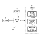
- FIG. 5 shows a configuration example of the transmission line design device 100 according to the embodiment of the present invention.
- the transmission line design device 100 shown in FIG. 5 includes a computer main body 41, an input device 42, a display 43, and a storage device 44 as hardware, as in the case of a general computer system such as a personal computer. There is.
- the storage device 44 shown in FIG. 5 holds a transmission line topology design program 51 that can be executed by the computer main body 41. Further, the storage device 44 is provided with a storage area for holding the initial data 52 and D0 of the regional transmission network model and the optimized data 53 and Dy of the regional transmission network model.
- the initial data 52 of the regional transmission network model is created and prepared in advance by the designer before executing the transmission line topology design program 51, or is automatically created by the transmission line topology design program 51. Further, when the transmission line topology design program 51 processes the initial data 52 and D0 of the regional transmission network model, the optimized data 53 of the regional transmission network model is automatically generated as the output data Dy.
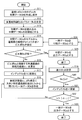
- FIG. 6 shows an example of the transmission network topology design method and the processing procedure of the transmission line design program according to the embodiment of the present invention. Further, the details of step S19 in FIG. 6 are shown in FIG. That is, the operation of the transmission line design device 100 shown in FIG. 5 is shown in FIGS. 6 and 7. The operations shown in FIGS. 6 and 7 will be described below.
- the computer main body 41 creates the initial data D0 of the model of the communication path topology by the input operation of the designer or by the predetermined algorithm included in the transmission line topology design program 51, and is stored on the storage device 44. Save to.
- the initial data D0 is, for example, data having a mesh-like communication path configuration as shown in FIG.
- the computer main body 41 accepts the input operation of the designer related to the value of the parameter n of the multiple failure resistance.
- the computer main body 41 determines the parameter n of multiple fault tolerance by the transmission line topology design program 51.
- the parameter n of multiple failure resistance is set to "2". It is limited to a value higher than or higher.
- step S13 the computer main body 41 that executes the transmission line topology design program 51 reads the initial data D0 from the storage device 44, and sets this as the initial value of the intermediate data Dx. After that, the computer main body 41 executes each step by executing the transmission line topology design program 51.
- step S14 the computer main body 41 extracts all the building group Bx whose "number of communication paths" is larger than n + 1 from the model of the intermediate data Dx.
- step S15 the computer main body 41 determines whether the extracted building group Bx does not exist, or has been processed and is empty. When the extracted building group Bx exists and there are unprocessed buildings and the computer main body 41 is not empty (No), the computer main body 41 proceeds to the process of step S16. When the extracted building group Bx does not exist or the unprocessed building does not exist and is empty (Yes), the computer main body 41 outputs the intermediate data Dx as the output data Dy (S25). End the process.
- step S16 the computer main body 41 calculates “both end road values d_i, j” for each communication path connected to the building group Bx.
- the computer main body 41 calculates "both end road values d_i, j" by the following equation (1).
- d_i, j d_i ⁇ d_j ⁇ ⁇ ⁇ (1)
- d_i "Number of communication roads” in the building on one end of one specific communication road
- d_j “Number of communication roads” in the building on the other end of the communication road
- step S17 the computer main body 41 initializes the index k to “1”.
- step S18 the computer main body 41 extracts the specific communication path having the k-th largest "both-end road values d_i, j", and creates the result of thinning out the specific communication path from the intermediate data Dx as temporary data Dt.
- the thinning of the specific communication path in step S18 is "temporary deletion" and has not been finalized yet. Therefore, the result of "temporary deletion" is temporary data Dt.
- step S19 the computer main body 41 performs the process of "minimum cut calculation" shown in detail in FIG. 7. The content of this process will be described later, but as a result, the computer main body 41 specifies the minimum number of cuts Nc.
- the buildings B11, B16, B61, and B66 at the four corners are excluded from the calculation.
- each building in the four corners has a "number of communication paths" of "2" from the beginning, and is connected to each building in the four corners in order to withstand simultaneous failures of two or more communication paths. Since it is not possible to thin out the inter-station communication path L, these are excluded from the processing.
- step S20 the computer main body 41 determines whether or not the minimum number of cuts Nc specified in step S19 is equal to or less than the parameter n of multiple failure resistance, that is, whether or not the condition of “Nc ⁇ n” is satisfied.
- the computer main body 41 proceeds to step S21 if the minimum number of cuts Nc is equal to or less than the multiple failure resistance parameter n (Yes), and proceeds to step S21 if the minimum number of cuts Nc exceeds the multiple failure resistance parameter n (No). Proceed to S24. That is, when the condition of "Nc ⁇ n" is satisfied, the condition of multiple failure tolerance is not satisfied due to the influence of the specific communication path thinned out immediately before as "temporary deletion" in step S18. Therefore, the computer main body 41 discards the temporary data Dt in which the "temporary deletion" is reflected, and proceeds to step S21 in order to search for the next thinning target communication path.
- step S21 the computer main body 41 adds +1 to the index k to update this value. Then, in step S22, the computer main body 41 determines whether or not the updated index k value is larger than the absolute value of the "both end road values d_i, j", that is, the condition of "k>
- step S23 the computer main body 41 outputs the current temporary data Dt as output data Dy, and ends this process.
- step S24 the computer main body 41 allocates the current temporary data Dt to the subsequent intermediate data Dx. That is, the computer main body 41 accepts the "temporary deletion" of the specific communication path in step S18 as the intermediate data Dx, and proceeds to step S14.
- step S31 the computer main body 41 generates various dividing lines SL1 to SLn passing through the specific communication path Ld on the model of the temporary data Dt, respectively.
- the specific communication path Ld corresponds only to the “temporary deletion” communication path thinned out in step S18 immediately before.
- step S32 the computer main body 41 calculates the number of cuts Nc1 to Ncn of the communication path crossed by each of the various dividing lines SL1 to SLn, respectively.
- step S33 the computer main body 41 selects the minimum value thereof from the cut numbers Nc1 to Ncn calculated in step S32, and sets it as the minimum cut number Nc.
- ⁇ Changes in composition due to optimization> 8 to 11 show changes in the configuration when the transmission network topology design method is applied to the regional transmission network model in which the communication path has a mesh configuration.
- FIG. 8 shows an example of the initial state
- FIGS. 9 and 10 show an example during processing
- FIG. 11 shows an example of the processing result. That is, when the transmission line design device 100 shown in FIG. 5 executes the transmission line topology design program 51 of each procedure shown in FIGS. 6 and 7, the topology on the model changes as shown in FIGS. 8 to 11. To do.
- FIG. 9 shows the intermediate result in which the computer main body 41 executes the transmission line topology design program 51 and thins out some inter-station communication lines L from the initial state of FIG. 8, that is, the state of the intermediate data Dx at a certain point in time. Has been done.
- the connection points between the buildings shown by the thin broken lines represent the inter-station communication paths L that are no longer thinned out.
- the specific communication paths LA, LB, and LC to be processed are indicated by thick broken lines.
- FIG. 9 for example, for a building BA, there are four inter-station communication paths L connecting the building BA to another building located adjacent to the building BA. This means that the "number of communication roads" of the building BA is "4". Similarly, in the example of FIG. 9, the "number of communication roads” is "4" for each of the buildings BB, BC, BD, BE, and BF.
- each building BA, BB, BC, BD, BE, and BF are extracted as the building group Bx, respectively.
- the communication path to be processed in step S16 of FIG. 6 is a communication path connecting the buildings included in the building group Bx, it corresponds to each of the specific communication paths LA, LB, and LC in FIG. ..
- the “number of communication path directions" d_i in the building on one end side of the specific communication path LA is "4", etc.
- the "number of communication paths" d_j in the end-side building is "4". Therefore, based on the above equation (1), the calculation result of the "both end road values d_i, j" of the specific communication path LA is "16".
- the calculation result of the “both end road values d_i, j” is “16”.
- any of the specific communication paths LA, LB, and LC are candidates that can be selected as thinning targets.
- the communication path to be thinned out is selected in step S18 of FIG. Since the value of the index k is "1" at first, the communication path having the largest "both end road values d_i, j" is thinned out first.
- the "both end road values d_i, j" is "16", which is the maximum. In such a case, for example, one specific communication path is randomly selected from the largest specific communication paths LA, LB, and LC and thinned out.
- FIG. 10 shows a state in which one specific communication path LA is thinned out and reduced from the model having the configuration shown in FIG.
- the specific communication path Ld of interest in step S31 shown in FIG. 7 is one communication path thinned out immediately before the processing. That is, in the example of FIG. 10, only the specific communication path LA thinned out immediately before corresponds to the specific communication path Ld in step S31.
- the one dividing line SL2 shown in FIG. 10 is a fictitious line that divides the entire model into two regions, and is limited to those that cross the position of the specific communication path Ld thinned out as "temporary deletion". ing.
- the dividing line SL2 divides the inter-station communication path L at three points other than the specific communication path Ld. That is, the number of cuts of the dividing line SL2 is "3".
- the number of cuts is calculated for each of a large number of n (the number is undecided) dividing lines SL1 to SLn, but in the example of FIG. 10, it is assumed that the number of cuttings of the dividing line SL2 is the minimum. There is. Therefore, in the example of FIG. 10, the minimum number of cuts Nc calculated in step S19 of FIG. 6 is “3”.
- the model having the configuration shown in FIG. 11 can be generated from the model having the configuration shown in FIG. Comparing these configurations, it can be seen that the number of inter-station communication paths L connecting the buildings is significantly reduced in the model of FIG. That is, since the total number of inter-station communication paths L required can be reduced while maintaining the multiple failure tolerance specified by the parameter n, the topology can be optimized so as to reduce the equipment cost and the operating cost.
- the initial data D0 is created so that the inter-station communication path L exists between the adjacent buildings for all the buildings constituting the regional transmission network 10.
- the configuration of the initial data D0 may be changed as necessary as shown in (1) and (2) below.
- (1) The combination of the communication paths L between stations in the initial data D0 is changed so as to reflect the actual optical fiber laying state in the regional transmission network 10.
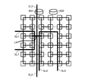
- dividing line In the transmission network topology design method and transmission line design program shown in FIG. 6, in order to evaluate the suitability of the specific communication line thinned out as temporary deletion in step S18, the minimum number of cuts Nc calculated in step S19 is used. There is. Further, when calculating the minimum number of cuts Nc, a plurality of dividing lines SL1 to SLn are generated in step S31 shown in FIG. An example of such a plurality of dividing lines SL1, SL2, and SL3 is shown in FIG. In the example of FIG. 12, only three types of dividing lines are shown, but in actual processing, more dividing lines are generated.
- the three dividing lines SL1, SL2, and SL3 are all assigned to positions that cross the specific communication path LA in the "temporarily deleted" state that was thinned out immediately before. Further, the three dividing lines SL1, SL2, and SL3 are all assigned to divide the entire model into two regions.
- this dividing line SL1 divides each station-to-station communication path L indicated by a solid line at four points. That is, in the case of the dividing line SL1 in FIG. 12, the number of cuts Nc1 in step S32 of FIG. 7 becomes “4”.
- the number of cuts Nc2 in step S32 of FIG. 7 is “3”.
- the third dividing line SL3 in FIG. 12 divides each station-to-station communication path L shown by the solid line at seven points, the number of cuts Nc3 in step S32 of FIG. 7 becomes “7”. ..
- the smallest “3” among the number of cuts “4” of the dividing line SL1, the number of cuts “3” of the dividing line SL2, the number of cuts “7” of the dividing line SL3, etc. is shown in FIG. It is calculated as the minimum number of cuts Nc in the "minimum cut calculation".
- the transmission line design device of the present invention is In a transmission network having a large number of bases, an initial data holding unit that holds initial data of a transmission network model in which a plurality of bases adjacent to each other are connected by a communication path and is configured in a mesh shape as a whole.
- the initial data of the transmission network model held by the initial data holding unit is acquired, and the number of directions of the communication path connected to each base is larger than the specified value from among a large number of bases in the transmission network model.
- the bases of one group are extracted, the communication paths of the first group connecting the bases of the first group are extracted from each of the communication paths, and each of the communication paths of the first group is set at one end thereof.
- the connected first base and the second base connected to the other end are specified, and the number of directions of the communication path at the first base and the direction of the communication path at the second base are specified.
- the both-end route values are calculated according to the number, and among the communication paths of the first group, those whose both-end route values satisfy a predetermined condition are specified as the communication paths to be thinned out, and the initial stage of the transmission network model.
- a model calculation unit that generates output data that reflects the communication path to be thinned out for the data. It is characterized by including a data output unit that outputs the output data generated by the model calculation unit.
- the transmission line design device of (1) above by extracting the bases of the first group, it is possible to identify the bases having a large margin against multiple failures of the communication paths, that is, the bases having a margin to thin out the communication paths. .. Further, since the communication path of the first group connects the bases of the first group to each other, it can be used as a thinning candidate. Further, the both-end road values calculated for each of the communication paths of the first group can be used to determine the priority in the communication paths of the thinning candidate. Therefore, among the communication paths of the thinning candidate, the one having a high priority can be thinned out. As a result, the optimized transmission network topology is obtained as the output data. In other words, under the condition of maintaining availability against multiple failures, it is possible to easily design an optimized communication path topology in consideration of suppressing the required amount of equipment.
- the transmission line design device of the present invention carries out each procedure shown in FIG. 6, and in step S18, the number of directions d_i of the communication path at one end of the specific communication path and the communication path at the other end.
- the end-to-end direction values d_i and j are calculated as the product of the number of directions d_j.
- the transmission line design device specifies the communication path to be thinned out in order from the communication path of the first group extracted as the building group Bx with the largest value of both ends. Then, the identification of the communication path to be thinned out is repeated until a predetermined end condition is satisfied.
- the transmission line design device of (2) above while maintaining the availability of the transmission network against multiple failures specified by the parameter n, the communication lines that can be thinned out are selected in order from the one with the highest priority, and the transmission network is selected. The total number of communication paths included in can be efficiently reduced.
- the transmission line design device of the present invention implements each procedure shown in FIGS. 6 and 7, and divides the entire transmission network model into two regions in step S31 of FIG. 7.
- a plurality of division lines SL1 to SLn. Is determined, the number of communication paths crossed by each of the dividing lines is calculated as the number of cuts Nc1 to Ncn in step S32, the minimum value of the number of divisions, that is, the minimum number of cuts Nc is specified in step S33, and the thinning target is specified. Whether or not the communication path satisfies a predetermined condition is specified based on the minimum value of the number of divisions.
- the transmission line design device of (3) above it is determined whether or not the temporary deletion of the specific communication path to be thinned out, which is of interest, maintains availability against multiple failures defined by the parameter n.
- the minimum number of cuts Nc required for this can be specified.
- the transmission line design device of the present invention implements each procedure shown in FIG. 6, and as a transmission network model to be processed, a plurality of regional bases each accommodating a traffic of a large number of user terminals, and a plurality of regional bases. It is premised on a model of a regional transmission network that includes multiple superior bases that accommodate the traffic of regional bases. Further, the minimum value of the number of divisions is limited to 2 or more by the parameter n of the multiple failure resistance in step S12.
- the transmission line design device of (4) above even if a large-scale disaster occurs in the regional transmission network and two or more failure occurrence points L01 and L02 occur at the same time as shown in FIG. 4B, the communication base is isolated. Can be avoided. That is, it is possible to secure another communication path that bypasses the plurality of failure occurrence points L01 and L02.
- the transmission network topology design method of the present invention is: In a transmission network having a large number of bases, a procedure for acquiring initial data of a transmission network model in which a plurality of bases adjacent to each other are connected by a communication path and the whole is configured in a mesh shape, and A procedure for extracting the first group bases in which the number of directions of the communication path connected to each base is larger than the specified value from a large number of bases in the transmission network model, and A procedure for extracting a communication path of the first group connecting the bases of the first group from each communication path and a procedure of extracting the communication path of the first group.
- a first base connected to one end and a second base connected to the other end are specified, and the number of directions of the communication path in the first base.
- the procedure for calculating the both-end route value according to the number of routes of the communication path at the second base are specified as thinning target communication paths, and the thinning target communication path is reflected in the initial data of the transmission network model.
- Procedures for generating output data and It is characterized by including.
- the transmission network topology design method of (4) above by extracting the bases of the first group, a base having a large margin against multiple failures of the communication path, that is, a base having a margin to thin out the communication path can be obtained. Can be identified. Further, since the communication path of the first group connects the bases of the first group to each other, it can be used as a thinning candidate. In addition, the both-end road values calculated for each of the communication paths of the first group can be used to determine the priority order in the communication paths of the thinning candidate. Therefore, among the communication paths of the thinning candidate, the one having a high priority can be thinned out. As a result, the optimized transmission network topology is obtained as the output data. In other words, under the condition of maintaining availability against multiple failures, it is possible to easily design an optimized communication path topology in consideration of suppressing the required amount of equipment.
- the double-ended road values d_i and j are the number of communication road directions d_i at the base at one end of the specific communication road in step S18. It is calculated as the product of the number of directions d_j of the communication path at the other end base. Further, in steps S14 to S24, among the communication paths of the first group extracted as the building group Bx, the communication paths to be thinned out are specified in order from the one having the largest value on both ends, and a predetermined end condition is set. The identification of the communication path to be thinned out is repeated until the condition is satisfied.
- the communication paths that can be thinned out are selected in order from the one with the highest priority while maintaining the availability of the transmission network against multiple failures specified by the parameter n. , The total number of communication paths included in the transmission network can be efficiently reduced.
- a plurality of division lines SL1 to SLn that divide the entire transmission network model into two regions are defined in step S31 of FIG.
- the number of communication paths crossed by each of the divided lines is calculated as the number of cuts Nc1 to Ncn in step S32, the minimum value of the number of divided lines, that is, the minimum number of cuts Nc is specified in step S33, and the thinned-out target communication path is determined. Whether or not a predetermined condition is satisfied is specified based on the minimum value of the number of divisions.
- the transmission line design program of the present invention is On the computer In a transmission network having a large number of bases, a procedure for acquiring initial data of a transmission network model in which a plurality of bases adjacent to each other are connected by a communication path and the whole is configured in a mesh shape. A procedure for extracting the first group of bases in which the number of directions of the communication path connected to each base is larger than the specified value from a large number of bases in the transmission network model. A procedure for extracting a communication path of the first group that connects the bases of the first group from each communication path. For each of the communication paths of the first group, a first base connected to one end and a second base connected to the other end are specified, and the number of directions of the communication path in the first base.
- the transmission line design program of (8) above by extracting the bases of the first group, a base having a large margin against multiple failures of the communication path, that is, a base having a margin to thin out the communication path is specified. it can. Further, since the communication path of the first group connects the bases of the first group to each other, it can be used as a thinning candidate. In addition, the both-end road values calculated for each of the communication paths of the first group can be used to determine the priority order in the communication paths of the thinning candidate. Therefore, among the communication paths of the thinning candidate, the one having a high priority can be thinned out. As a result, the optimized transmission network topology is obtained as the output data. In other words, under the condition of maintaining availability against multiple failures, it is possible to easily design an optimized communication path topology in consideration of suppressing the required amount of equipment.
Landscapes
- Engineering & Computer Science (AREA)
- Computer Networks & Wireless Communication (AREA)
- Signal Processing (AREA)
- Data Exchanges In Wide-Area Networks (AREA)
Abstract
Le but de la présente invention est de faciliter la conception d'une topologie de trajet de communication optimisée en prenant en considération la suppression d'une quantité d'installation nécessaire dans une condition pour maintenir une disponibilité contre de multiples défaillances d'un réseau. Un dispositif de conception de la voie de transmission (100) exécute : une étape (S14) pour extraire les bases d'un premier groupe ayant un grand nombre de trajets de communication connectés parmi de nombreuses bases sur la base des données initiales (D0) d'un modèle de réseau de transmission ; une étape (S16) pour extraire les trajets de communication du premier groupe qui connectent les bases du premier groupe entre elles ; une étape (S16) pour calculer les valeurs de trajets (d_i, j) des deux extrémités pour chacun des trajets de communication du premier groupe ; et des étapes (S18 à S24) pour spécifier un trajet ayant les valeurs de trajets des deux extrémités qui satisfont une condition prescrite comme trajet de communication à rétrécir, et pour générer des données de sortie Dy dans lesquelles le trajet de communication à rétrécir est reflété dans les données initiales du modèle de réseau de transmission. Ce dispositif de conception de trajet de transmission peut générer des données de sortie (Dy) optimisées par extraction successive, à partir du modèle des données initiales (D0), de trajets de communication pouvant être éliminés.
Priority Applications (3)
| Application Number | Priority Date | Filing Date | Title |
|---|---|---|---|
| US17/619,982 US11824762B2 (en) | 2019-06-17 | 2019-06-17 | Transmission path design apparatus, transmission network topology design method, and transmission path design program for designing a communication path topology optimized in view of reducing amount of equipment needed |
| PCT/JP2019/023936 WO2020255216A1 (fr) | 2019-06-17 | 2019-06-17 | Dispositif de conception de trajet de transmission, procédé de conception de topologie de réseau de transmission et programme de conception de trajet de transmission |
| JP2021528068A JP7151896B2 (ja) | 2019-06-17 | 2019-06-17 | 伝送路設計装置、伝送網トポロジ設計方法、および伝送路設計プログラム |
Applications Claiming Priority (1)
| Application Number | Priority Date | Filing Date | Title |
|---|---|---|---|
| PCT/JP2019/023936 WO2020255216A1 (fr) | 2019-06-17 | 2019-06-17 | Dispositif de conception de trajet de transmission, procédé de conception de topologie de réseau de transmission et programme de conception de trajet de transmission |
Publications (1)
| Publication Number | Publication Date |
|---|---|
| WO2020255216A1 true WO2020255216A1 (fr) | 2020-12-24 |
Family
ID=74040183
Family Applications (1)
| Application Number | Title | Priority Date | Filing Date |
|---|---|---|---|
| PCT/JP2019/023936 Ceased WO2020255216A1 (fr) | 2019-06-17 | 2019-06-17 | Dispositif de conception de trajet de transmission, procédé de conception de topologie de réseau de transmission et programme de conception de trajet de transmission |
Country Status (3)
| Country | Link |
|---|---|
| US (1) | US11824762B2 (fr) |
| JP (1) | JP7151896B2 (fr) |
| WO (1) | WO2020255216A1 (fr) |
Citations (1)
| Publication number | Priority date | Publication date | Assignee | Title |
|---|---|---|---|---|
| JP2009118201A (ja) * | 2007-11-07 | 2009-05-28 | Nippon Telegr & Teleph Corp <Ntt> | 網トポロジ・リンク容量設計処理方法とシステムおよびプログラム |
Family Cites Families (56)
| Publication number | Priority date | Publication date | Assignee | Title |
|---|---|---|---|---|
| US6278689B1 (en) * | 1998-04-22 | 2001-08-21 | At&T Corp. | Optical cross-connect restoration technique |
| US6856627B2 (en) * | 1999-01-15 | 2005-02-15 | Cisco Technology, Inc. | Method for routing information over a network |
| US6970451B1 (en) * | 1999-10-12 | 2005-11-29 | At&T Corp. | Smart routers-simple optics: network architecture for IP over WDM |
| US7274869B1 (en) * | 1999-11-29 | 2007-09-25 | Nokia Networks Oy | System and method for providing destination-to-source protection switch setup in optical network topologies |
| US6970417B1 (en) * | 1999-12-28 | 2005-11-29 | At&T Corp. | Methods and systems for fast restoration in a mesh network of optical cross connects |
| US6744769B1 (en) * | 2000-10-19 | 2004-06-01 | Nortel Networks Limited | Path provisioning on ring-based networks |
| JP3700596B2 (ja) * | 2001-03-14 | 2005-09-28 | 日本電気株式会社 | 通信ネットワーク及びパス設定方法並びにパス設定用プログラム |
| US20020191247A1 (en) * | 2001-04-30 | 2002-12-19 | Xiang Lu | Fast restoration in optical mesh network |
| US7941047B2 (en) * | 2001-07-18 | 2011-05-10 | Alcatel-Lucent Usa Inc. | Method for engineering connections in a dynamically reconfigurable photonic switched network |
| US7630635B1 (en) * | 2001-07-19 | 2009-12-08 | Alcatel-Lucent Usa Inc. | Channel wavelength assignment with transient reduction |
| US7209975B1 (en) * | 2002-03-15 | 2007-04-24 | Sprint Communications Company L.P. | Area based sub-path protection for communication networks |
| JP2003289325A (ja) * | 2002-03-28 | 2003-10-10 | Fujitsu Ltd | 通信ネットワークの迂回経路設計方法 |
| US7606494B1 (en) * | 2002-06-04 | 2009-10-20 | Broadwing Corporation | Optical transmission systems, devices, and methods |
| US7174096B2 (en) * | 2002-07-24 | 2007-02-06 | Ciena Corporation | Method and system for providing protection in an optical communication network |
| US8457497B2 (en) * | 2003-01-31 | 2013-06-04 | Ciena Corporation | Optimized directionless optical add/drop module systems and methods |
| US7660235B2 (en) * | 2003-03-20 | 2010-02-09 | Alcatel-Lucent Usa Inc. | Low latency shared data path allocation |
| US7043250B1 (en) * | 2003-04-16 | 2006-05-09 | Verizon Corporate Services Group Inc. | Systems and methods for forming and operating a communications network |
| US7283741B2 (en) * | 2003-06-06 | 2007-10-16 | Intellambda Systems, Inc. | Optical reroutable redundancy scheme |
| US20050197993A1 (en) * | 2003-09-12 | 2005-09-08 | Lucent Technologies Inc. | Network global expectation model for multi-tier networks |
| US7957266B2 (en) * | 2004-05-28 | 2011-06-07 | Alcatel-Lucent Usa Inc. | Efficient and robust routing independent of traffic pattern variability |
| US7660526B2 (en) * | 2004-11-12 | 2010-02-09 | Cisco Technology, Inc. | Through channel loss prevention at a WDM node |
| WO2007086157A1 (fr) * | 2006-01-25 | 2007-08-02 | Hitachi Communication Technologies, Ltd. | Système de réseau |
| JP2007243567A (ja) * | 2006-03-08 | 2007-09-20 | Fujitsu Ltd | 通信パス計算方法及び装置 |
| US20080181605A1 (en) * | 2007-01-30 | 2008-07-31 | Paparao Palacharla | Multi-degree optical node architectures |
| US7924705B2 (en) * | 2007-03-01 | 2011-04-12 | Ciena Corporation | Method and system for span-based connection aggregation |
| US8947999B2 (en) * | 2007-08-17 | 2015-02-03 | Tellabs Operations, Inc. | Shared protection method and apparatus for reconfigurable optical add-drop multiplexer (roadm) based mesh networks |
| US8849115B2 (en) * | 2008-03-11 | 2014-09-30 | Ciena Corporation | Directionless optical architecture and highly available network and photonic resilience methods |
| US8116630B2 (en) * | 2008-12-08 | 2012-02-14 | At&T Intellectual Property I, L.P. | Methods for dynamic wavelength add/drop in a ROADM optical network |
| EP2251999B1 (fr) * | 2009-05-13 | 2013-08-28 | ADVA Optical Networking SE | Procédé de transmission de données et réseau de transmission d'un signal optique numérique sur des liens et des réseaux de transmission optique |
| JP5398839B2 (ja) * | 2009-09-14 | 2014-01-29 | 日本電信電話株式会社 | 帯域可変通信方法、帯域可変通信装置、伝送帯域決定装置、伝送帯域決定方法、ノード装置、通信路設定システム、及び通信路設定方法 |
| WO2011047715A1 (fr) * | 2009-10-20 | 2011-04-28 | Telefonaktiebolaget Lm Ericsson (Publ) | Nœud de commutation de transport optique avec fonction de mise en trame |
| US8750706B2 (en) * | 2010-03-12 | 2014-06-10 | Ciena Corporation | Shared photonic mesh |
| US8995988B2 (en) * | 2010-07-21 | 2015-03-31 | Softbank Bb Corp. | Communication characteristic analyzing system, communication characteristic analyzing method, and communication characteristic analyzing program |
| JP5537462B2 (ja) * | 2011-02-24 | 2014-07-02 | 株式会社日立製作所 | 通信ネットワークシステム及び通信ネットワーク構成方法 |
| US20140056584A1 (en) * | 2011-03-15 | 2014-02-27 | Telefonaktiebolaget L M Ericsson (Publ) | Reconfigurable Optical Add-Drop Multiplexer and Optical Network Element |
| CN102790653B (zh) * | 2011-05-19 | 2015-02-18 | 武汉邮电科学研究院 | 可重构光分插复用器和可重构光分插复用方法 |
| JP5743809B2 (ja) * | 2011-08-26 | 2015-07-01 | 株式会社日立製作所 | 網管理システムおよび網管理方法 |
| US8965198B2 (en) * | 2012-04-13 | 2015-02-24 | Fujitsu Limited | System and method for shared mesh restoration in optical networks |
| US8854955B2 (en) * | 2012-11-02 | 2014-10-07 | Ciena Corporation | Mesh restoration and bandwidth allocation systems and methods for shared risk connection groups |
| JP5949515B2 (ja) * | 2012-12-13 | 2016-07-06 | 富士通株式会社 | ネットワーク設計装置、ネットワーク設計方法、及びネットワーク設計プログラム |
| US9160651B2 (en) * | 2013-07-24 | 2015-10-13 | Telefonaktiebolaget L M Ericsson (Publ) | Metric biasing for bandwidth aware tie breaking |
| US9215028B2 (en) * | 2013-09-09 | 2015-12-15 | Huawei Technologies Co., Ltd. | Photonic switch chip for scalable reconfigurable optical add/drop multiplexer |
| JP2015056747A (ja) * | 2013-09-11 | 2015-03-23 | 富士通株式会社 | ネットワーク設計装置、ネットワーク設計方法、及びネットワーク設計プログラム |
| WO2015127992A1 (fr) * | 2014-02-28 | 2015-09-03 | Telefonaktiebolaget L M Ericsson (Publ) | Procédé et appareil pour établir un chemin de communication dans un réseau optique |
| EP3114511A4 (fr) * | 2014-03-07 | 2017-10-11 | Aeponyx Inc. | Procédés et système pour composants optiques pouvant être accordés en longueur d'onde et sous-systèmes |
| BR112017004888A2 (pt) * | 2014-09-11 | 2017-12-05 | Univ Arizona | sistema de comunicação óptica, e, método de reconfiguração de um trajeto de sinal. |
| US9692503B2 (en) * | 2014-11-04 | 2017-06-27 | Verizon Patent And Licensing Inc. | Network protection through excess directions of reconfigurable optical add/drop multiplexor (ROADM) |
| JP2016208354A (ja) * | 2015-04-24 | 2016-12-08 | 富士通株式会社 | 光通信システム、及び、光通信方法 |
| US9866315B2 (en) * | 2015-04-24 | 2018-01-09 | Lumentum Operations Llc | Super-channel multiplexing and de-multiplexing using a phased array switching engine |
| JP6627645B2 (ja) * | 2016-05-18 | 2020-01-08 | 富士通株式会社 | 光伝送制御装置及び光信号波長決定方法 |
| US10264507B2 (en) * | 2016-08-22 | 2019-04-16 | Verizon Patent And Licensing Inc. | Next generation intelligent mesh network with fronthaul and backhaul services |
| US20190109638A1 (en) * | 2017-02-02 | 2019-04-11 | Omer F. Yilmaz | Optical restoration method in optical networks controlled by a l0 sdn controller |
| US10674558B2 (en) * | 2017-05-24 | 2020-06-02 | Vivint Wireless, Inc. | Mesh topology radio |
| US10432342B1 (en) * | 2018-04-18 | 2019-10-01 | At&T Intellectual Property I, L.P. | Routing and regenerator planning in a carrier's core reconfigurable optical network |
| JP2019212684A (ja) * | 2018-05-31 | 2019-12-12 | 株式会社クオンタムドライブ | 可視光無線通信用の受光装置 |
| US20200177299A1 (en) * | 2018-11-29 | 2020-06-04 | Infinera Corporation | Apparatus and method to reduce the impact of coherent crosstalk in optical networks |
-
2019
- 2019-06-17 US US17/619,982 patent/US11824762B2/en active Active
- 2019-06-17 WO PCT/JP2019/023936 patent/WO2020255216A1/fr not_active Ceased
- 2019-06-17 JP JP2021528068A patent/JP7151896B2/ja active Active
Patent Citations (1)
| Publication number | Priority date | Publication date | Assignee | Title |
|---|---|---|---|---|
| JP2009118201A (ja) * | 2007-11-07 | 2009-05-28 | Nippon Telegr & Teleph Corp <Ntt> | 網トポロジ・リンク容量設計処理方法とシステムおよびプログラム |
Non-Patent Citations (1)
| Title |
|---|
| YAMAMOTO, HIROSHI ET AL.: "Highly available metro transport network using multiple direction OXC", IEICE TECHNICAL REPORT, vol. 118, no. no. 465, 25 February 2019 (2019-02-25), pages 261 - 265 * |
Also Published As
| Publication number | Publication date |
|---|---|
| JPWO2020255216A1 (fr) | 2020-12-24 |
| US20220360520A1 (en) | 2022-11-10 |
| US11824762B2 (en) | 2023-11-21 |
| JP7151896B2 (ja) | 2022-10-12 |
Similar Documents
| Publication | Publication Date | Title |
|---|---|---|
| CN101911421B (zh) | 恢复配电网中的电力的方法 | |
| US6922661B2 (en) | Process for initializing and updating the topology of a high-voltage or medium-voltage electrical power station | |
| CN109474023B (zh) | 智能配电网区段实时更新方法、系统、存储介质及终端 | |
| CN110858777B (zh) | 传输网络中同路由隐患的分析方法和设备 | |
| CN106789646A (zh) | 业务传输路径确定方法及装置 | |
| JP5488206B2 (ja) | 光ファイバ線路設計支援装置及びプログラム | |
| US20110158083A1 (en) | Determining Connectivity in a Failed Network | |
| JP7151896B2 (ja) | 伝送路設計装置、伝送網トポロジ設計方法、および伝送路設計プログラム | |
| CN110233796B (zh) | 一种基于加权路由算法的电力通信网优化方法及设备 | |
| CN114520935A (zh) | 一种路径选择方法以及路径选择装置 | |
| CN116014568A (zh) | 基于间隔拓扑的主接线类型识别方法、装置、设备及介质 | |
| CN108493908B (zh) | 一种考虑通信约束的区域保护分区方法 | |
| CN112612201B (zh) | 自动化系统、创建自动化系统的方法和计算机可读介质 | |
| CN107248952B (zh) | 一种业务替代路由确定方法及系统 | |
| CN110009240B (zh) | 一种电力系统可靠性评估方法 | |
| CN110048422B (zh) | 一种配电网可靠性快速评估方法 | |
| CN115754586B (zh) | 一种接地故障区间定位方法、装置及电子设备 | |
| EP2575063B1 (fr) | Procédé de routage et de câblage automatique pour réseaux de centrales | |
| Ramanathan et al. | The hybrid model: a novel approach for transitioning from the bus-branch/planning to the node-breaker/operation system model | |
| CN109962812B (zh) | 一种电层离散业务反算方法及系统 | |
| KR20060017111A (ko) | 배전계통의 부하평준화를 위한 최적 배전계통 구성방법 | |
| CN113141009B (zh) | 一种用于开环电网转供电的决策方法及装置 | |
| JP4782509B2 (ja) | ケーブル工事計画情報管理システム | |
| CN119070895A (zh) | 一种光网络跨域网络规划方法及系统、存储介质 | |
| JP6632558B2 (ja) | ネットワークの検証最適化方法、プログラムおよび装置 |
Legal Events
| Date | Code | Title | Description |
|---|---|---|---|
| 121 | Ep: the epo has been informed by wipo that ep was designated in this application |
Ref document number: 19933617 Country of ref document: EP Kind code of ref document: A1 |
|
| ENP | Entry into the national phase |
Ref document number: 2021528068 Country of ref document: JP Kind code of ref document: A |
|
| NENP | Non-entry into the national phase |
Ref country code: DE |
|
| 122 | Ep: pct application non-entry in european phase |
Ref document number: 19933617 Country of ref document: EP Kind code of ref document: A1 |