WO2020255237A1 - Système de commande et procédé d'enregistrement d'informations - Google Patents
Système de commande et procédé d'enregistrement d'informations Download PDFInfo
- Publication number
- WO2020255237A1 WO2020255237A1 PCT/JP2019/024019 JP2019024019W WO2020255237A1 WO 2020255237 A1 WO2020255237 A1 WO 2020255237A1 JP 2019024019 W JP2019024019 W JP 2019024019W WO 2020255237 A1 WO2020255237 A1 WO 2020255237A1
- Authority
- WO
- WIPO (PCT)
- Prior art keywords
- information
- unit
- plc
- closing
- opening
- Prior art date
- Legal status (The legal status is an assumption and is not a legal conclusion. Google has not performed a legal analysis and makes no representation as to the accuracy of the status listed.)
- Ceased
Links
Images



Classifications
-
- G—PHYSICS
- G05—CONTROLLING; REGULATING
- G05B—CONTROL OR REGULATING SYSTEMS IN GENERAL; FUNCTIONAL ELEMENTS OF SUCH SYSTEMS; MONITORING OR TESTING ARRANGEMENTS FOR SUCH SYSTEMS OR ELEMENTS
- G05B19/00—Program-control systems
- G05B19/02—Program-control systems electric
- G05B19/04—Program control other than numerical control, i.e. in sequence controllers or logic controllers
- G05B19/048—Monitoring; Safety
-
- G—PHYSICS
- G05—CONTROLLING; REGULATING
- G05B—CONTROL OR REGULATING SYSTEMS IN GENERAL; FUNCTIONAL ELEMENTS OF SUCH SYSTEMS; MONITORING OR TESTING ARRANGEMENTS FOR SUCH SYSTEMS OR ELEMENTS
- G05B19/00—Program-control systems
- G05B19/02—Program-control systems electric
- G05B19/04—Program control other than numerical control, i.e. in sequence controllers or logic controllers
- G05B19/05—Programmable logic controllers, e.g. simulating logic interconnections of signals according to ladder diagrams or function charts
Definitions
- the present invention relates to a control system and an information recording method.
- the PLC includes a contact relay for input / output
- the contacts are consumed by the opening / closing operation, so there is a request to record how much the PLC is consumed and utilize it for replacement, maintenance, etc. of the PLC unit.
- the management computer since the management computer does not know the number of times of opening and closing of the contacts of the PLC unit, the management computer side performs analysis based on the number of times of opening and closing, and for example, the PLC unit. No exchange proposal can be made.
- the present invention has been made in view of the above circumstances, and an object of the present invention is to provide a control system and an information recording method capable of grasping the number of times of opening and closing of contacts of a PLC by an information processing device connected to the PLC. ..
- the control system of the present invention includes a PLC and an information processing device.
- the PLC first stores the opening / closing number information indicating the number of times of opening / closing by counting the number of times the contact of the relay element is opened / closed and the relay element having a contact between the internal circuit and the external device. It includes a processor stored in the unit and a transmission unit that transmits the opening / closing number information stored in the first storage unit to the information processing apparatus.
- the information processing device stores the second storage unit that stores the PLC identification information that identifies the PLC, the reception unit that receives the opening / closing count information, and the opening / closing count information received by the receiving unit in association with the PLC identification information. It includes a control unit to be stored in the unit.
- the present invention by associating the identification information of the PLC with the information processing number of times of opening and closing and storing it in the storage unit of the information processing device, the number of times of opening and closing of the contacts of the PLC can be grasped by the information processing device connected to the PLC. it can.
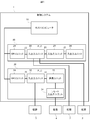
- FIG. 1 Schematic diagram of the control system according to the embodiment of the present invention
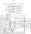
- FIG. 1 Hardware configuration diagram of host computer and PLC according to the embodiment of the present invention
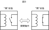
- FIG. 1 shows an example of the opening and closing operation of the relay element which concerns on embodiment of this invention.
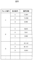
- Sequence diagram of the control system according to the embodiment of the present invention The figure which shows an example of the opening / closing count information stored in the CPU unit which concerns on embodiment of this invention.
- the control system 1 is a system for controlling various devices. As shown in FIG. 1, the control system 1 includes a host computer 10 for aggregating and processing various information, and a plurality of PLCs (Programmable Logic Controllers) 20 and 30 for controlling various devices.
- PLCs Protein Logic Controllers
- the host computer 10 is an information processing device that aggregates and processes various types of information.
- the host computer 10 is communicably connected to the PLC 20 and the PLC 30, respectively.
- the host computer 10 is installed with engineering tools that are dedicated software for operating the PLC 20 and the PLC 30, such as designing, programming, debugging, and maintaining the PLC 20 and the PLC 30.
- the host computer 10 activates the engineering tool and executes various functions for operating the PLC 20 and the PLC 30.
- the host computer 10 periodically acquires operating information from the PLC 20 and the PLC 30 at a frequency specified by the user.
- the PLC 20 and the PLC 30 are control devices that include a plurality of units and control various devices.
- the PLC 20 controls the device 2 and the device 3, and the PLC 30 controls the device 4 and the device 5.
- the device 2, the device 3, the device 4 and the device 5 are examples of the external devices described in the claims.
- the PLC 20 is dedicated to connecting a CPU (Central Processing Unit) unit 21 for controlling other units, a plurality of input / output units 22, 23, 24 for transmitting and receiving data between various devices, and each unit. It is equipped with a bus 25.
- the input / output unit 22 is connected to the device 2 and the device 3, respectively.
- the PLC 30 is a communication unit 33 for communicating between a CPU unit 31 for controlling another unit, an input / output unit 32 for transmitting / receiving data between the device 5 and the remote input / output unit 34.
- a remote input / output unit 34 for transmitting / receiving data to / from the device 4 and a dedicated bus 35 for connecting the units are provided.
- the communication unit 33 and the remote input / output unit 34 are adopted, and the communication unit 33 and the remote input / output unit 34 are connected to a LAN (Local Area Network). ) It is connected with a cable.
- LAN Local Area Network
- the host computer 10 includes a CPU 11 that executes various processes, a memory 12 that stores various information, a communication IF (Interface) 13 for transmitting and receiving information, a display 14 that displays information, and a keyboard 15 that accepts operations. And a hard disk drive 16 for storing various information.
- a CPU 11 that executes various processes
- a memory 12 that stores various information
- a communication IF (Interface) 13 for transmitting and receiving information
- a display 14 that displays information
- a keyboard 15 that accepts operations.
- a hard disk drive 16 for storing various information.
- the CPU 11 reads the engineering tool stored in the hard disk drive 16 into the memory 12 and executes it to execute various processes described later.
- the CPU 11 is an example of the control unit described in the claims.
- the memory 12 includes a volatile memory and a non-volatile memory, and is used as a work area of the CPU 11. In addition, stores a control program, a BIOS (Basic Input Output System), and the like executed by the CPU 11 for the basic operation of the host computer 10. It is the main memory.
- BIOS Basic Input Output System
- the communication IF13 is a communication device for communicating information with PLCs 20 and 30 such as a network card and a network adapter.
- the communication IF 13 is an example of the receiving unit described in the claims.
- the display 14 is a device for displaying information such as a liquid crystal panel and a projector.
- the display 14 displays information necessary for the user to operate the keyboard 15 to input information, a processing result of the CPU 11, and the like.
- the display 14 is an example of the display unit described in the claims.
- the keyboard 15 is a device that receives an operation for inputting information.
- the hard disk drive 16 is an auxiliary storage device that stores information.
- the hard disk drive 16 stores the above-mentioned engineering tools, setting information referred to in the processing described later, various information acquired from the PLCs 20 and 30, and the like.
- the hard disk drive 16 is an example of the second storage unit described in the claims.
- the CPU unit 21 of the PLC 20 includes a communication IF 211 for communicating information, a CPU 212 for executing various processes, a memory 213 for storing various information, and a dedicated bus control circuit 214 for controlling the dedicated bus 25.
- the communication IF211 is a communication circuit for communicating information with the host computer 10.
- the communication IF211 is an example of the transmission unit described in the claims.
- the CPU 212 reads the ladder program generated by the host computer 10 into the memory 213 and executes it to execute various processes for controlling the devices 2, 3 and the like via the input / output units 22, 23, 24 and the like. ..
- the CPU 212 is an example of the processor described in the claims.
- the memory 213 is a main storage device that includes a volatile memory and a non-volatile memory and is used as a work area of the CPU 212.
- the memory 213 is an example of the first storage unit described in the claims.
- the dedicated bus control circuit 214 is a control circuit that controls the dedicated bus 25. Communication between the CPU unit 21 and the input / output unit 22 is performed via the dedicated bus 25 using the dedicated bus control circuit 214 as an interface.
- the input / output unit 22 of the PLC 20 generates a CPU 221 that controls each device, a memory 222 that stores various information, and a digital signal that is activated in response to an analog signal input from the device 2 and transmitted to the CPU unit 21.
- a relay element 226 for driving the device 3 whose opening and closing is controlled by the output circuit 224, and a dedicated bus control circuit 227 for controlling the dedicated bus 25 are provided.
- the CPU 221 controls various parts included in the input / output unit 22. For example, when the CPU 221 receives a signal instructing output from the CPU unit 21, it activates the output circuit 224 to control the contacts of the relay element 226 to be closed. Then, the CPU 221 writes information indicating that the contact of the relay element 226 is in the closed state to the memory 222. Further, when the contact of the relay element 225 is closed by the input signal received from the device 2 and the input circuit 223 is activated, the CPU 221 outputs information indicating that the contact of the relay element 225 is closed to the memory 222. Write.
- the CPU 212 is an example of the processor described in the claims.
- the memory 222 is a main storage device that includes a volatile memory and a non-volatile memory and is used as a work area of the CPU 221.
- the memory 222 is an example of the third storage unit described in the claims.
- the input circuit 223 is an electronic circuit for generating a signal to be activated and transmitted to the CPU unit 21 in response to an input signal from the device 2.
- the contact of the relay element 225 is closed, the input circuit 223 generates a digital signal, and the generated digital signal is transmitted to the CPU unit 21 via the CPU 221.
- the output circuit 224 is an electronic circuit for driving or stopping the device 3. Specifically, the output circuit 224 is activated by an instruction from the CPU 221 to close the contacts of the relay element 226. As a result, a voltage is applied to the device 3 and the device 3 is driven.
- the input circuit 223 and the output circuit 224 are examples of the internal circuits described in the claims.
- the dedicated bus control circuit 227 is a control circuit that controls the dedicated bus 25.
- the relay element 225 and the relay element 226 are mechanical relays having contacts.
- the contacts of the relay element 225 are in the open state as shown in FIG. 3 when the input signal is not received from the device 2. Then, when the input signal is received from the device 2, the coil is excited and the contacts are closed.
- the contacts of the relay element 226 are in the open state when no signal is received from the CPU unit 21. Then, when a signal is received from the CPU unit 21, the coil is excited and the contacts are closed. At the contacts of the relay element 225 or the relay element 226, the current is not cut off when it is in the closed state, and the current is cut off when it is in the open state.
- the number of times of opening and closing of the contact is the number of opening and closing operations counted as one time when the contact is changed from the open state to the closed state and then opened again.
- the number of times the contact is opened and closed is a count of the number of times the contact has changed from the open state to the closed state.
- the operation of the control system 1 will be described with reference to the drawings.
- the device 2 transmits an analog signal to the input / output unit 22 (step S11).
- the relay element 225 of the input / output unit 22 is closed.
- the input circuit 223 is activated to generate a digital signal, and the generated digital signal is transmitted to the CPU unit 21 via the CPU 221 and the dedicated bus control circuit 227.
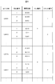
- the CPU 221 writes the closing information, which is information indicating that the closed state has been reached, to the memory 222. Then, the input / output unit 22 transmits the closing information to the CPU unit 21 via the dedicated bus 25 (step S12). Based on the received closing information, the CPU 212 of the CPU unit 21 stores the opening / closing number information indicating the opening / closing number of each contact in the memory 213. If the open / close count information is already stored in the memory 213, the CPU 212 adds the open / close count to update the open / close count information. As shown in FIG.
- the open / close count information stored in the memory 213 includes a slot number for identifying the slot in which the input / output unit is set, a contact number for identifying the opened / closed contact, and an open / close count. Including.
- the slot number is an example of the slot identification information described in the claims.
- the CPU unit 21 transmits an output request signal representing a request for outputting an analog signal to the input / output unit 22 (step S21). Then, the contact of the relay element 226 of the input / output unit 22 is closed. Then, the output circuit 224 of the input / output unit 22 transmits an analog signal to the device 3 (step S22). Specifically, a voltage is applied to the device 3 to drive the device 3. Then, the CPU 221 writes the closing information, which is information indicating that the closed state is reached, to the memory 222.
- the CPU 221 reads the closing information from the memory 222 and transmits it to the CPU unit 21 (step S23). Based on the received closing information, the CPU 212 of the CPU unit 21 stores the opening / closing number information indicating the opening / closing number of each contact in the memory 213.
- the unit ID is an identifier for identifying the input / output unit 22. Specifically, the unit ID adopts a serial number, a serial number, or the like that can physically identify each individual.
- the unit ID is an example of the unit identification information described in the claims.
- the host computer 10 periodically transmits an open / close count information request signal requesting open / close count information to each PLC including the PLC 20 in a nighttime batch process once a day, for example, at a predetermined cycle (step S31). ).
- the CPU 212 of the CPU unit 21 of the PLC 20 transmits a unit ID request signal requesting transmission of the unit ID to the input / output unit 22 (step S32).
- the CPU 212 reads information representing the unit ID from the memory 222 and transmits it to the CPU unit 21 (step S33).
- the CPU 212 of the CPU unit 21 reads the open / close count information from the memory 213, and transmits the read open / close count information and the unit ID information received in step S33 to the host computer 10 (step S34).
- the CPU 11 of the host computer 10 stores the open / close count information in the hard disk drive 16 based on the open / close count information and the unit ID information received from each PLC.
- the open / close count information stored in the host computer 10 includes the open / close count associated with the combination of the unit ID and the contact number, as shown in FIG. Further, the opening / closing count information includes a PLC number that identifies the PLC and a slot number. The combination of the PLC number and the slot number is an identifier that identifies the PLC and the slot in which the target input / output unit is installed. Further, the hard disk drive 16 of the host computer 10 stores PLC information of each PLC such as PLC20 and PLC30 which are communication targets. The PLC information includes a PLC number for identifying the PLC and a unit ID for identifying the input / output units arranged in each PLC.
- the host computer 10 When the host computer 10 establishes communication with the PLC 20 in step S31, the host computer 10 specifies the PLC number of the communication partner PLC 20 based on the PLC information. Then, the host computer 10 stores the open / close count information received in step S34 in the hard disk 16 in association with the PLC number representing the PLC 20.
- the PLC number is an example of the PLC identification information described in the claims.
- the operation of rearranging the input / output units will be described next.
- the person in charge operates the host computer 10 and inputs the contents of the rearrangement.
- the host computer 10 transmits the open / close count information of the input / output unit 32 to the CPU unit 21 of the PLC 20 together with the corresponding slot number (step S41).
- the CPU 212 of the CPU unit 21 updates the value corresponding to the received slot number among the open / close counts stored in the memory 213 to the value of the number of times included in the received open / close count information.
- the CPU 212 of the CPU unit 21 counts from the value of the number of updates.
- the hard disk drive 16 of the host computer 10 has device information representing the characteristics of the device connected to each contact of each slot, and threshold determination reference information representing a reference for determining a threshold for displaying an alarm. Is stored in advance.
- the device information includes the load current value indicating the magnitude of the current flowing through the load connected to the contact and the magnitude of the voltage applied to the load for each combination of the PLC number, slot number, and contact number. This is the information associated with the load voltage value representing the value.
- the load current value and the load voltage value are values determined by the load connected to the contact, that is, the device. After designing what kind of equipment is to be connected to the PLC, the system person operates the keyboard 15 of the host computer 10 to input information about the load current value and the load voltage value of each contact.
- the threshold value determination reference information is information for determining the threshold value for displaying an alarm.
- the person in charge of the system inputs the information for determining the threshold value in consideration of the regulation that serves as a guideline for the life of each input / output unit. For example, the person in charge of the system sets threshold value determination reference information with a value of 80% of the number of times of opening and closing as a threshold value for the number of times of opening and closing specified according to the load voltage value and the load current value as a guideline for the life. It is stored in the hard disk drive 16 of the host computer 10.
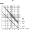
- the threshold value determination reference information is information in which a criterion for determining a threshold value based on a load voltage value and a load current value is defined. For example, in the threshold value determination reference information, as shown in the graph shown in FIG. 8, the correlation between the load current value and the threshold value is defined for each load voltage value.
- the CPU 11 of the host computer 10 reads out the engineering tool stored in the hard disk drive 16 periodically, for example, every day, and starts the alarm display process shown in FIG.
- the CPU 11 reads the open / close count information, the device information, and the threshold value determination reference information from the hard disk drive 16 to acquire the open / close count and the threshold value for each contact (step S51).
- the CPU 11 acquires the load current value and the load voltage value for each contact from the device information, and calculates the threshold value based on the load voltage value and the load current value acquired from the threshold value determination reference information.
- the CPU 11 sets the corresponding threshold value from the threshold value determination reference information shown in the graph shown in FIG. For example, a threshold value of 15 (10,000 times) is acquired.
- the CPU 11 determines whether or not there is a contact whose opening / closing number exceeds the threshold value (step S52).
- the CPU 11 determines that there is no contact whose opening / closing number exceeds the threshold value (step S52: No)
- the CPU 11 ends the alarm display process.
- the CPU 11 determines that there is a contact whose opening / closing number exceeds the threshold value (step S52: Yes)
- the CPU 11 generates alarm information and proposal information (step S53).
- the CPU 11 generates a message indicating that the contact whose opening / closing number exceeds the threshold value is nearing the end of its life as alarm information.
- the alarm information is a message that "the contact (2) of the input / output unit (U9912) of the PLC (1) and the slot (2) is nearing the end of its life.”
- the alarm information includes a PLC number, a slot number, a unit ID, and the like for identifying a contact that exceeds the threshold value.
- the CPU 11 analyzes the ladder program stored in the hard disk drive 16 and generates proposal information indicating a proposal of how to arrange the input / output units in each PLC.
- the CPU 11 generates proposal information that is expected to reach the end of its life when the number of times of opening and closing of each contact of each PLC is close to each other when the input / output unit is actually arranged. For example, the CPU 11 calculates a predicted value of the number of times of opening and closing of each contact per fixed period from the fixed cycle processing for inputting and outputting signals specified in the ladder program. Specifically, when the process of opening and closing the contact P N times is executed every T time, the CPU 11 calculates K P (X), which is a predicted value of the number of times the contact P is opened and closed after X hours, by the following equation. calculate.
- CP is the number of times of opening and closing of the contact P at the time of prediction. Then, the CPU 11 opens and closes each contact of each PLC when the input / output unit is actually arranged, based on the calculated predicted value of each contact and the remaining number of times of opening and closing until the life of each contact stored in the hard disk drive 16. Propose information that is expected to reach the end of its life when the number of times is close to each other is generated. Then, the CPU 11 determines that, for example, when two input / output units are exchanged, the number of times of opening and closing of each contact of each PLC is expected to reach the end of the life when compared with the arrangement included in the PLC information.
- a message indicating that the input / output unit is to be replaced is generated as proposal information.
- the proposed information proposes, for example, to replace the input / output unit (U9912) of PLC (1) and slot (2) with the input / output unit (U4017) of PLC (2) and slot (1). Is the message.
- the input / output unit may be exchanged within the same PLC or between a plurality of PLCs.
- the proposal information does not have to be the proposal for exchanging the arrangement of the input / output units described above.
- the proposal information may be information that proposes the arrangement of used input / output units at the time of system introduction.
- information indicating the number of times of opening and closing of the used input / output unit may be stored in the hard disk drive 16 in advance.
- the CPU 11 can analyze the ladder program of the system to be introduced and calculate the predicted value of the number of times of opening and closing of each contact.
- the display 14 displays the opening / closing count information, the alarm information, and the proposal information (step S54).
- the displayed open / close count information is tabular information indicating the open / close count for each contact as shown in FIG.
- the displayed alarm information and proposal information are information generated in the process of step S53.
- the host computer 10 can grasp the opening / closing number of each PLC by storing the unit ID of each PLC in association with the opening / closing number information. As a result, the host computer 10 can execute a function of supporting system maintenance, operation, and the like by utilizing the number of times of opening and closing of each PLC that has been grasped.
- the control system 1 not the slot number of each PLC but the unit ID that can physically identify each input / output unit and the opening / closing number information are associated with each other. Therefore, even if the slot in which the input / output unit is installed is changed, the open / close count information is inherited and the correct open / close count is recorded.
- control system 1 since the control system 1 records the number of times of opening and closing for each contact, the relay life of each input / output unit can be grasped more accurately. In addition, it is possible to consider changing the arrangement of equipment for each contact during maintenance. However, in order to simplify the introduction of the system, the number of times of opening and closing may be recorded for each input / output unit instead of for each contact. In this way, the time and effort required to introduce the system can be reduced, and the approximate relay life of each input / output unit can be grasped.
- the relay life of each PLC can be averaged by displaying the proposal information that is expected to reach the end of the life when the number of times of opening and closing of each contact of each PLC is close to each other when the input / output unit is actually arranged.
- the frequency of system outages can be kept low.
- the threshold value is determined based on the load voltage value and the load current value, and it is determined whether or not to display the alarm information.
- the host computer 10 may generate the proposal information by predicting the relay life based on the load voltage value and the load current value. As a result, the accuracy of the proposal information is improved, and useful proposal information is generated.
- the input / output units 22, 23, 24, 32 and the remote input / output unit 34 are examples of the interface units described in the claims.
- An example of an input / output mixing unit including both an input circuit and an output circuit is shown as an interface unit.
- the interface unit may be an input unit including only an input circuit, or an output unit including only an output circuit. That is, the interface unit includes all the input / output mixing unit, the input unit, and the output unit.
- the PLC is provided with a power supply unit that supplies power, a servo amplifier, a motion unit for controlling a servomotor, an analog unit for inputting / outputting data to / from an analog device including a sensor, and the like. Is also good.
- a relay element having a make contact that is normally in the open state and is in the closed state when the coil is excited is illustrated.
- it may be a relay element having a break contact that is normally closed and opens when the coil is excited.
- the number of times of opening and closing may be counted when the state changes from the closed state to the open state.
- a relay element having other contacts may be used. The method of counting the number of times of opening and closing may be appropriately adjusted in relation to the life of the relay element.
- the host computer 10 may further store model information for each input / output unit. As a result, it is possible to propose replacement of the same type of input / output unit, so that more realistic proposal information can be generated.
- the host computer 10 can be realized by using an ordinary computer without using a dedicated device.
- the host computer 10 that executes the above-mentioned processing may be configured by installing the program in the computer from a recording medium in which the program for executing any of the above-mentioned is executed in the computer.
- the host computer 10 may be configured by a plurality of servers, computers and the like operating in cooperation with each other, or by a dedicated device and a server, a computer and the like operating in cooperation with each other.
- a database server different from the host computer 10 may be connected by a LAN-to-LAN connection, and various information may be stored in the database server.
- the method for supplying the program to the computer is arbitrary. For example, it may be supplied via a communication line, a communication network, a communication system, or the like.
- the OS Oleting System
- the part other than the functions provided by the OS may be provided by a program.
- the timing at which the host computer 10 generates and displays the proposal information is the same as the timing at which the alert information is displayed.
- the timing of generating and displaying the proposal information may be different from the display of the alert information.
- the host computer 10 may determine the variation in the number of times of opening and closing of each contact, and generate and display the proposal information when the variation becomes large. Further, the host computer 10 may generate and display the proposal information at the timing of performing the maintenance of the control system 1.
- step S53 of the alarm display process shown in FIG. 9 when the CPU 11 actually arranges the input / output units, the proposal information is generated so that the number of times of opening and closing of each contact of each PLC is expected to reach the end of the life.
- An example is shown.
- the method of generating proposal information is not limited to this.
- the proposal information generation rule may be stored in the hard disk drive 16 and the proposal information satisfying the generation rule may be generated. In this way, the method of generating the proposal information can be flexibly changed according to the characteristics, the field, and the like of the control system 1.
- an example including a load current value and a load voltage value is shown as device information indicating the characteristics of the device, but in addition, when the load current is an alternating current, the power factor is used, and when the load current is a direct current.
- the time constant and the like may be included in the device information.
- the host computer 10 may display an alarm or generate proposal information in consideration of the number of times of opening and closing and the time of being closed. In this way, when the closed state affects the relay life, the relay life can be grasped more accurately.
Landscapes
- Physics & Mathematics (AREA)
- General Physics & Mathematics (AREA)
- Engineering & Computer Science (AREA)
- Automation & Control Theory (AREA)
- Programmable Controllers (AREA)
Abstract
La présente invention concerne un système de commande comprenant un API (20) et un ordinateur hôte (10). L'API (20) comprend une mémoire (213), des éléments de relais (225, 226) ayant un point de contact entre un circuit interne et un appareil externe, des UCT (212, 221) qui comptent le nombre de fois que les contacts des éléments de relais (225, 226) sont ouverts et fermés et stockent des informations de comptage d'ouverture/ fermeture indiquant le nombre de fois où la mémoire (213) est ouverte et fermée et une IF de communication (211) qui transmet les informations de comptage d'ouverture/ fermeture stockées dans la mémoire (213) à l'ordinateur hôte (10). L'ordinateur hôte (10) comprend un lecteur de disque dur (16) qui stocke un numéro d'API qui identifie l'API (20), une IF de communication (13) qui reçoit les informations de comptage d'ouverture/ fermeture et une UCT (11) qui stocke les informations de comptage d'ouverture/ fermeture reçues par l'IF de communication (13) dans le lecteur de disque dur (16) en association avec le numéro d'API.
Priority Applications (3)
| Application Number | Priority Date | Filing Date | Title |
|---|---|---|---|
| CN201980097457.XA CN113950648A (zh) | 2019-06-18 | 2019-06-18 | 控制系统及信息记录方法 |
| JP2019571753A JP6732146B1 (ja) | 2019-06-18 | 2019-06-18 | 制御システムおよび情報記録方法 |
| PCT/JP2019/024019 WO2020255237A1 (fr) | 2019-06-18 | 2019-06-18 | Système de commande et procédé d'enregistrement d'informations |
Applications Claiming Priority (1)
| Application Number | Priority Date | Filing Date | Title |
|---|---|---|---|
| PCT/JP2019/024019 WO2020255237A1 (fr) | 2019-06-18 | 2019-06-18 | Système de commande et procédé d'enregistrement d'informations |
Publications (1)
| Publication Number | Publication Date |
|---|---|
| WO2020255237A1 true WO2020255237A1 (fr) | 2020-12-24 |
Family
ID=71738588
Family Applications (1)
| Application Number | Title | Priority Date | Filing Date |
|---|---|---|---|
| PCT/JP2019/024019 Ceased WO2020255237A1 (fr) | 2019-06-18 | 2019-06-18 | Système de commande et procédé d'enregistrement d'informations |
Country Status (3)
| Country | Link |
|---|---|
| JP (1) | JP6732146B1 (fr) |
| CN (1) | CN113950648A (fr) |
| WO (1) | WO2020255237A1 (fr) |
Cited By (1)
| Publication number | Priority date | Publication date | Assignee | Title |
|---|---|---|---|---|
| JP2023030603A (ja) * | 2021-08-23 | 2023-03-08 | 株式会社日本製鋼所 | 射出成形機および射出成形機の部品の寿命予測方法 |
Citations (7)
| Publication number | Priority date | Publication date | Assignee | Title |
|---|---|---|---|---|
| JPH01255003A (ja) * | 1988-04-05 | 1989-10-11 | Mitsubishi Electric Corp | プログラマブルコントローラ |
| JPH08335103A (ja) * | 1995-06-07 | 1996-12-17 | Mitsubishi Electric Corp | プラント進行状態表示システム |
| JP2003150211A (ja) * | 2001-11-12 | 2003-05-23 | Omron Corp | 制御システム及びスレーブ並びに制御情報収集装置及び制御情報収集方法 |
| JP2004021393A (ja) * | 2002-06-13 | 2004-01-22 | Toshiba Corp | 多重化制御システム |
| JP2005251015A (ja) * | 2004-03-05 | 2005-09-15 | Digital Electronics Corp | エディタ装置、エディタプログラムおよびそのプログラムを記録した記録媒体、ならびに制御システム、制御モニタプログラムおよびそのプログラムを記録した記録媒体 |
| JP2006293420A (ja) * | 2005-04-05 | 2006-10-26 | Jtekt Corp | 分散制御装置 |
| JP2013235377A (ja) * | 2012-05-08 | 2013-11-21 | Mitsubishi Electric Corp | 接点出力機器 |
Family Cites Families (2)
| Publication number | Priority date | Publication date | Assignee | Title |
|---|---|---|---|---|
| JP2561105Y2 (ja) * | 1991-07-25 | 1998-01-28 | 横河電機株式会社 | 高信頼性形リレー装置 |
| JP7411482B2 (ja) * | 2020-04-02 | 2024-01-11 | ニデックインスツルメンツ株式会社 | リレー装置 |
-
2019
- 2019-06-18 JP JP2019571753A patent/JP6732146B1/ja active Active
- 2019-06-18 WO PCT/JP2019/024019 patent/WO2020255237A1/fr not_active Ceased
- 2019-06-18 CN CN201980097457.XA patent/CN113950648A/zh active Pending
Patent Citations (7)
| Publication number | Priority date | Publication date | Assignee | Title |
|---|---|---|---|---|
| JPH01255003A (ja) * | 1988-04-05 | 1989-10-11 | Mitsubishi Electric Corp | プログラマブルコントローラ |
| JPH08335103A (ja) * | 1995-06-07 | 1996-12-17 | Mitsubishi Electric Corp | プラント進行状態表示システム |
| JP2003150211A (ja) * | 2001-11-12 | 2003-05-23 | Omron Corp | 制御システム及びスレーブ並びに制御情報収集装置及び制御情報収集方法 |
| JP2004021393A (ja) * | 2002-06-13 | 2004-01-22 | Toshiba Corp | 多重化制御システム |
| JP2005251015A (ja) * | 2004-03-05 | 2005-09-15 | Digital Electronics Corp | エディタ装置、エディタプログラムおよびそのプログラムを記録した記録媒体、ならびに制御システム、制御モニタプログラムおよびそのプログラムを記録した記録媒体 |
| JP2006293420A (ja) * | 2005-04-05 | 2006-10-26 | Jtekt Corp | 分散制御装置 |
| JP2013235377A (ja) * | 2012-05-08 | 2013-11-21 | Mitsubishi Electric Corp | 接点出力機器 |
Cited By (2)
| Publication number | Priority date | Publication date | Assignee | Title |
|---|---|---|---|---|
| JP2023030603A (ja) * | 2021-08-23 | 2023-03-08 | 株式会社日本製鋼所 | 射出成形機および射出成形機の部品の寿命予測方法 |
| JP7628919B2 (ja) | 2021-08-23 | 2025-02-12 | 株式会社日本製鋼所 | 射出成形機および射出成形機の部品の寿命予測方法 |
Also Published As
| Publication number | Publication date |
|---|---|
| JPWO2020255237A1 (ja) | 2021-09-13 |
| JP6732146B1 (ja) | 2020-07-29 |
| CN113950648A (zh) | 2022-01-18 |
Similar Documents
| Publication | Publication Date | Title |
|---|---|---|
| CN104834579B (zh) | 故障预测系统和故障预测设备 | |
| US20180373233A1 (en) | Failure predicting apparatus and machine learning device | |
| CN103718122B (zh) | 现场仪器以及现场仪器的动作方法 | |
| US7752025B2 (en) | Parameter identification for field devices used in automation technology | |
| WO2015072528A1 (fr) | Procede pour determiner l'etat d'une batterie d'accumulateurs, systeme de determination d'etat et programme informatique | |
| CN101652738A (zh) | 用于在数据处理系统中给系统功率损失通知定阈值的系统和方法 | |
| JP2021096639A (ja) | 制御方法、制御装置、機械設備、制御プログラム、記録媒体 | |
| JP6517991B1 (ja) | 異常予兆診断システム、管理装置、及び異常予兆診断方法 | |
| CN106403188A (zh) | 一种空调维护方法及其维护装置 | |
| JP2022032684A (ja) | 設備保全支援システム及び設備保全支援方法 | |
| JP7046320B2 (ja) | 産業機器の制御装置及び産業機器のデータ収集システム | |
| EP3338188B1 (fr) | Procédé pour déterminer une durée moyenne de fonctionnement avant défaillance d'un dispositif électrique | |
| CN102819245B (zh) | 用于监控设备的方法 | |
| US20040210664A1 (en) | System and method for transmitting data | |
| JP6732146B1 (ja) | 制御システムおよび情報記録方法 | |
| US20240211895A1 (en) | Maintenance scheduling device and maintenance scheduling method | |
| JP2009217708A (ja) | リモート装置及びi/o機器の交換時期管理システム | |
| JP2003103485A (ja) | ロボット制御装置とその制御方法およびその管理システム | |
| CN116490857A (zh) | 电子设备具有的记录介质的保养服务的提供方法以及系统 | |
| WO1999001806A1 (fr) | Procede de gestion de l'historique d'un equipement et systeme de gestion d'historique | |
| JP7781361B2 (ja) | 予測装置、予測方法、予測プログラム、および記録媒体 | |
| JP2016058048A (ja) | 施設管理装置及び施設管理方法 | |
| KR20230101720A (ko) | 에너지 비용 절감을 위한 공장 생산 설비 최적 운영 방법, 장치, 시스템 및 컴퓨터 프로그램 | |
| WO2022030061A1 (fr) | Dispositif d'identification de facteur de non-fonctionnement, procédé, et programme | |
| JP2011233088A (ja) | 保守管理システム |
Legal Events
| Date | Code | Title | Description |
|---|---|---|---|
| ENP | Entry into the national phase |
Ref document number: 2019571753 Country of ref document: JP Kind code of ref document: A |
|
| 121 | Ep: the epo has been informed by wipo that ep was designated in this application |
Ref document number: 19934234 Country of ref document: EP Kind code of ref document: A1 |
|
| NENP | Non-entry into the national phase |
Ref country code: DE |
|
| 122 | Ep: pct application non-entry in european phase |
Ref document number: 19934234 Country of ref document: EP Kind code of ref document: A1 |