WO2020255271A1 - Appareil électronique et procédé associé - Google Patents
Appareil électronique et procédé associé Download PDFInfo
- Publication number
- WO2020255271A1 WO2020255271A1 PCT/JP2019/024165 JP2019024165W WO2020255271A1 WO 2020255271 A1 WO2020255271 A1 WO 2020255271A1 JP 2019024165 W JP2019024165 W JP 2019024165W WO 2020255271 A1 WO2020255271 A1 WO 2020255271A1
- Authority
- WO
- WIPO (PCT)
- Prior art keywords
- devices
- radio
- channel
- characteristic
- characteristic information
- Prior art date
- Legal status (The legal status is an assumption and is not a legal conclusion. Google has not performed a legal analysis and makes no representation as to the accuracy of the status listed.)
- Ceased
Links
Images





Classifications
-
- G—PHYSICS
- G01—MEASURING; TESTING
- G01S—RADIO DIRECTION-FINDING; RADIO NAVIGATION; DETERMINING DISTANCE OR VELOCITY BY USE OF RADIO WAVES; LOCATING OR PRESENCE-DETECTING BY USE OF THE REFLECTION OR RERADIATION OF RADIO WAVES; ANALOGOUS ARRANGEMENTS USING OTHER WAVES
- G01S11/00—Systems for determining distance or velocity not using reflection or reradiation
- G01S11/02—Systems for determining distance or velocity not using reflection or reradiation using radio waves
- G01S11/06—Systems for determining distance or velocity not using reflection or reradiation using radio waves using intensity measurements
-
- G—PHYSICS
- G01—MEASURING; TESTING
- G01S—RADIO DIRECTION-FINDING; RADIO NAVIGATION; DETERMINING DISTANCE OR VELOCITY BY USE OF RADIO WAVES; LOCATING OR PRESENCE-DETECTING BY USE OF THE REFLECTION OR RERADIATION OF RADIO WAVES; ANALOGOUS ARRANGEMENTS USING OTHER WAVES
- G01S5/00—Position-fixing by co-ordinating two or more direction or position line determinations; Position-fixing by co-ordinating two or more distance determinations
- G01S5/02—Position-fixing by co-ordinating two or more direction or position line determinations; Position-fixing by co-ordinating two or more distance determinations using radio waves
- G01S5/0269—Inferred or constrained positioning, e.g. employing knowledge of the physical or electromagnetic environment, state of motion or other contextual information to infer or constrain a position
-
- G—PHYSICS
- G01—MEASURING; TESTING
- G01S—RADIO DIRECTION-FINDING; RADIO NAVIGATION; DETERMINING DISTANCE OR VELOCITY BY USE OF RADIO WAVES; LOCATING OR PRESENCE-DETECTING BY USE OF THE REFLECTION OR RERADIATION OF RADIO WAVES; ANALOGOUS ARRANGEMENTS USING OTHER WAVES
- G01S5/00—Position-fixing by co-ordinating two or more direction or position line determinations; Position-fixing by co-ordinating two or more distance determinations
- G01S5/02—Position-fixing by co-ordinating two or more direction or position line determinations; Position-fixing by co-ordinating two or more distance determinations using radio waves
- G01S5/0284—Relative positioning
-
- H—ELECTRICITY
- H04—ELECTRIC COMMUNICATION TECHNIQUE
- H04W—WIRELESS COMMUNICATION NETWORKS
- H04W4/00—Services specially adapted for wireless communication networks; Facilities therefor
- H04W4/02—Services making use of location information
- H04W4/029—Location-based management or tracking services
-
- G—PHYSICS
- G01—MEASURING; TESTING
- G01S—RADIO DIRECTION-FINDING; RADIO NAVIGATION; DETERMINING DISTANCE OR VELOCITY BY USE OF RADIO WAVES; LOCATING OR PRESENCE-DETECTING BY USE OF THE REFLECTION OR RERADIATION OF RADIO WAVES; ANALOGOUS ARRANGEMENTS USING OTHER WAVES
- G01S2205/00—Position-fixing by co-ordinating two or more direction or position line determinations; Position-fixing by co-ordinating two or more distance determinations
- G01S2205/01—Position-fixing by co-ordinating two or more direction or position line determinations; Position-fixing by co-ordinating two or more distance determinations specially adapted for specific applications
Definitions
- Embodiments of the present invention relate to electronic devices and methods.
- the problem to be solved by the present invention is to provide an electronic device and a method capable of estimating the position where the radio is installed with high accuracy.
- the electronic device includes a storage means, a receiving means, and an estimation means.
- the storage means stores position information indicating the first and second installation positions of a plurality of devices.
- the receiving means includes characteristic information of the first device obtained from the first propagation characteristic of the first device among the plurality of devices in the first channel and the second propagation characteristic of the first device in the second channel.
- the characteristic information of the second device obtained from the third propagation characteristic of the second device among the plurality of devices in the first channel and the fourth propagation characteristic of the second device in the second channel is received.
- the estimation means of the first and second devices from the first and second installation positions based on the position information, the characteristic information of the first device, and the characteristic information of the second device. Estimate the location where each is installed.
- FIG. 1 is a diagram for specifically explaining an example of a usage mode of the electronic device according to the first embodiment.
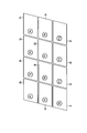
- FIG. 2 is a diagram for specifically explaining another example of the usage mode of the electronic device.
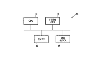
- FIG. 3 is a diagram showing an example of the hardware configuration of the electronic device.
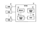
- FIG. 4 is a block diagram showing an example of the functional configuration of the electronic device.
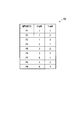
- FIG. 5 is a diagram showing an example of a data structure of position information stored in the position information storage unit.
- FIG. 6 is a sequence chart showing an example of the processing procedure of the electronic device and the plurality of radios when estimating the position where each of the plurality of radios is installed.
- FIG. 7 is a diagram showing an example of a data structure of characteristic information stored in the characteristic information storage unit.
- FIG. 8 is a block diagram showing an example of the functional configuration of the electronic device according to the second embodiment.
- FIG. 9 is a sequence chart showing the processing procedure of the electronic device and the plurality of radios when estimating the position where each of the plurality of radios is installed.
- FIG. 10 is a diagram showing an example of a data structure of characteristic information stored in the characteristic information storage unit.
- FIG. 11 is a flowchart showing a processing procedure of the secondary estimation process.
- FIG. 12 is a diagram for specifically explaining the secondary estimation process.
- FIG. 13 is a diagram for explaining an example of the re-estimation process.
- FIG. 14 is a diagram for explaining another example of the re-estimation process.
- each embodiment will be described with reference to the drawings.
- First, the first embodiment will be described.
- the electronic device according to the present embodiment for example, when a plurality of radios are installed at a plurality of predetermined installation positions, each of the plurality of radios is installed from the plurality of installation positions. It is used to estimate (identify) the position of the radio.
- FIG. 1 shows the positions P1 to P9 of the plurality of rooms 1a to 1c and the lighting devices arranged in each of the rooms 1a to 1c.
- lighting equipment is arranged at each of the positions P1 to P3 of the room 1a
- lighting equipment is arranged at each of the positions P4 to P6 of the room 1b
- positions P7 to P9 of the room 1c Lighting equipment is arranged in each of the above.
- each wireless device may communicate via a wireless master unit installed as appropriate, or may communicate by configuring a wireless mesh network.
- a radio ID for identifying the radio is assigned to each radio installed in each device. Therefore, it is possible to transmit a control signal to a specific radio by using the radio ID.
- the control signal is transmitted when the specific lighting equipment is controlled. It is not possible to identify the radio.
- the positions where a plurality of radios are installed are known as described above, but any of the locations for each of the installation positions is known.
- the position where each radio is installed that is, each installation position from the installation positions It is used to estimate the radio ID) assigned to the installed radio.
- the electronic device according to the present embodiment may be used, for example, in a photovoltaic power generation system.
- each of the plurality of solar panels 2a to 2l (that is, positions P1 to P12) A radio may be installed. According to this, since the power generation amount, temperature, etc. of each of the solar panels 2a to 2l can be collected via the radio, each of the solar panels 2a to 2l is based on the power generation amount, temperature, etc. The status (operating status or failure, etc.) can be monitored.
- the electronic device can also be used to estimate the position where each radio is installed from a plurality of installation positions (solar panels) in such a photovoltaic power generation system.
- radios for example, in the case of installing radios in a plurality of air conditioners in an air conditioning system, or installing radios in various facilities such as trains (air conditioners, motors, inverters, sensors, etc.). It can also be applied to such cases.
- FIG. 3 is a diagram showing an example of the hardware configuration of the electronic device according to the present embodiment.
- the electronic device 10 includes a CPU 11, a non-volatile memory 12, a main memory 13, a communication device 14, and the like.
- the CPU 11 is a hardware processor that controls the operation of each component in the electronic device 10.
- the CPU 11 executes a program loaded from the non-volatile memory 12 which is a storage device into the main memory 13.
- the communication device 14 is a device configured to execute wired communication or wireless communication.
- the electronic device 10 is communicably connected to each of the plurality of radios described above, and can transmit and receive various information (signals).
- the electronic device 10 is connected to each of the plurality of wireless devices so as to be capable of wireless communication.
- the electronic device 10 is connected to a wireless access point via, for example, a wired network.
- the wireless access point may be connected to a plurality of wireless devices so as to be capable of wireless communication by forming a star network.
- each radio may be connected by forming a wireless mesh network. That is, in the present embodiment, as long as the electronic device 10 is communicably connected to each of the plurality of radios, wired communication may be executed in a part of the electronic devices 10.
- the electronic device 10 may include other storage devices such as an HDD (Hard Disk Drive) and an SSD (Solid State Drive). Good.
- HDD Hard Disk Drive
- SSD Solid State Drive
- the electronic device 10 may further include an input device such as a mouse or a keyboard and a display device such as a display.
- an input device such as a mouse or a keyboard
- a display device such as a display.
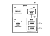
- FIG. 4 is a block diagram showing an example of the functional configuration of the electronic device 10.
- the electronic device 10 includes a measurement instruction unit 101, a characteristic information storage unit 102, a position information storage unit 103, and an estimation unit 104.
- the electronic device 10 is communicably connected to the plurality of radios 20 as described above.
- a part or all of the measurement instruction unit 101 and the estimation unit 104 are made to execute the program by the CPU 11 described above, that is, it is realized by software.
- a part or all of each of these parts 101 and 104 may be realized by hardware such as an IC (Integrated Circuit), or may be realized as a combination configuration of software and hardware.
- the characteristic information storage unit 102 and the position information storage unit 103 are realized by, for example, a non-volatile memory or another storage device.
- the measurement instruction unit 101 instructs each of the plurality of radios 20 to use a channel for measuring the propagation characteristics of each of the plurality of radios 20. Further, the measurement instruction unit 101 receives characteristic information obtained from the propagation characteristics measured by each of the plurality of radios 20 using the designated channel from each of the plurality of radios 20.
- the characteristic information storage unit 102 stores the characteristic information received by the measurement instruction unit 101.
- the position information storage unit 103 stores in advance position information indicating the installation position where each of the plurality of radios 20 is installed.
- the position information (installation position indicated by) stored in the position information storage unit 103 may be automatically extracted from, for example, a drawing showing a position where a plurality of radios 20 are installed, or a plurality of positions. It may be input by a worker or the like who installs the radio 20.
- the estimation unit 104 is a plurality of radios from among the plurality of installation positions indicated by the position information.
- the position where each of the 20s is installed that is, the correspondence between the installation position and the radio 20
- the estimation unit 104 estimates the radio (radio ID assigned to) installed at the installation position for each installation position indicated by the position information.
- FIG. 5 shows an example of the data structure of the position information stored in the position information storage unit 103 shown in FIG.
- the position information includes the X coordinate and the Y coordinate in association with the installation position ID.
- the installation position ID is identification information assigned to the installation position indicated by the position information (that is, the position where one radio 20 is installed).
- the X coordinate is the X coordinate value of the installation position to which the associated installation position ID is assigned.
- the Y coordinate is the Y coordinate value of the installation position to which the associated installation position ID is assigned.
- the X coordinate value and the Y coordinate value represent the position (installation position) where the radio 20 is installed.
- the position may be represented by three-dimensional coordinates by adding the Z coordinate value.
- the position information storage unit 103 stores position information including the X coordinate "1" and the Y coordinate "1" in association with the installation position ID "P1". According to this position information, the installation position ID "P1" is assigned, and one of the plurality of radios 20 is installed at the installation position where the X coordinate value is 1 and the Y coordinate value is 1. It is shown that it has been done.
- the position information storage unit 103 stores position information including the X coordinate "1" and the Y coordinate "2" in association with the installation position ID "P2". According to this position information, one of the plurality of radios 20 is installed at the installation position where the installation position ID "P2" is assigned, the X coordinate value is 1, and the Y coordinate position is 2. It is shown that it has been done.
- the installation positions that is, the installation position IDs "P1" to "P9" in which the plurality of radios 20 (that is, nine radios 20) are installed are assigned. It is possible to determine which of the radios 20 (radio ID) is installed at each of the nine installation positions).
- the measurement instruction unit 101 determines a channel (radio channel) to be used for measuring the propagation characteristics of each of the plurality of radios 20 (step S1). In step S1, a plurality of channels are determined.
- the measurement instruction unit 101 transmits measurement instruction information including a number indicating each of the plurality of channels determined in step S1 (hereinafter, referred to as a measurement channel number) to the target radio 20 (step S2).
- the measurement instruction information is transmitted to all the radios 20 by broadcasting, for example.
- the measurement instruction information includes a plurality of measurement channel numbers, and the measurement channel number may be any one as long as each of the plurality of radios 20 can identify the channel determined in step S1, for example, 920 MHz.
- the measurement channel number In the case of a band, a number defined for a channel such as 33, 42, 51, 60 can be used as the measurement channel number. Further, the center frequency of the channel or the like may be used as the measurement channel number.
- the measurement instruction information includes a period for measuring the propagation characteristics (hereinafter referred to as a measurement period) and a channel used in each of the plurality of radios 20 after the measurement of the propagation characteristics is completed. (Hereinafter, the switching destination channel number) is included.
- the measurement period and the switching destination channel number may be predetermined, for example, or may be dynamically determined by the measurement instruction unit 101.
- the measurement period may be the same period for the plurality of measurement channel numbers (that is, the plurality of channels determined in step S1), or different periods for each of the plurality of measurement channel numbers. It may be. Further, when the radio has a time measuring unit and these are synchronized, the measurement period is, for example, the time when the measurement of the propagation characteristic is started (hereinafter referred to as the measurement start time) and the measurement of the propagation characteristic is completed. It may be a period determined by the time to be measured (hereinafter referred to as the measurement end time). In this case, the measurement instruction information may include the measurement start time and the measurement end time for each measurement channel number.
- the switching destination channel number can be, for example, the channel before the measurement of the propagation characteristics is started, but it may be another channel. Further, for example, if the channel at the time when the measurement of the propagation characteristics is completed is continuously used, the measurement instruction information may not include the switching destination channel number.
- the measurement instruction information transmitted from the measurement instruction unit 101 (electronic device 10) in step S2 is received by the target radio 20.
- the target radio 20 switches the channel on which the target radio 20 executes communication based on a plurality of measurement channel numbers included in the received measurement instruction information (step S3).
- the measurement instruction information includes a plurality of measurement channel numbers, but in the measurement of propagation characteristics, it is necessary to transmit and receive signals between the plurality of radios 20 as described later. Therefore, within the same measurement period, the channels used (performing communication) in each of the plurality of radios 20 are unified.
- the channels indicated by each of the plurality of measurement channel numbers included in the measurement instruction information shall be used in a predetermined order.
- the order of using the channels indicated by each of the plurality of measurement channel numbers may be in ascending (younger) order of the measurement channel numbers, or is specified by the electronic device 10 (measurement instruction unit 101). You may.
- the specified order may be included in the measurement instruction information.
- each of the plurality of radios 20 sends a signal using the same channel among the plurality of channels indicated by each of the plurality of measurement channel numbers. It is ready to send and receive.
- the channel switched in step S3 (that is, the channel on which the target radio 20 executes communication) is referred to as a target channel.
- step S4 the target radio 20 starts measuring the propagation characteristics.
- the process of step S4 may be executed immediately after the process of step S3 is executed, and when the measurement instruction information received by the radio 20 includes the measurement start time, the measurement is performed. It may be executed when the start time is reached.
- the target radio 20 sends a signal for measuring the propagation characteristics (hereinafter referred to as a measurement signal) to the other plurality of radios 20 at random timings. Is transmitted by broadcasting (step S5).
- the measurement signal is transmitted using the channel of interest.
- the measurement signal includes a radio ID assigned to the target radio 20 (that is, a radio ID of the source of the measurement signal). It is also possible to determine the timing, order, and the like for the target radio 20 to transmit the measurement signal. In this case, the measurement signal may be transmitted according to the determined timing, order, and the like.
- the measurement signal is similarly transmitted by broadcasting from each of the plurality of radios 20 other than the target radio 20. Therefore, the target radio 20 receives the measurement signals transmitted from each of the other plurality of radios 20.
- the target radio 20 measures the propagation characteristics of the target radio 20 in the target channel based on the measurement signal (step S6).
- the propagation characteristic in the present embodiment may represent a characteristic related to a wireless communication environment between the target radio 20 and another radio 20. Specifically, for example, a received signal strength indicator (RSSI: Received Signal Strength Indicator) is measured as a propagation characteristic.
- RSSI Received Signal Strength Indicator
- the target radio 20 receives the measurement signal (measurement signal including the radio ID assigned to the other radio 20) transmitted from each of the other plurality of radios 20, but the step.
- the propagation characteristic between the target radio 20 and another radio 20 to which the radio ID included in the measurement signal is assigned is determined based on the measurement signal received by the target radio 20. Be measured. That is, the target radio 20 measures the propagation characteristics of each of the other radios 20 based on the measurement signals transmitted from each of the other plurality of radios 20.
- the propagation characteristics (propagation characteristics measured for each of the other radios 20) measured based on the measurement information in step S6 are assigned to the radio ID (the other radio 20) included in the measurement information. It is held inside the target radio 20 together with the radio ID).
- steps S5 and S6 may be executed a plurality of times after the process of step S4 is executed and before the process of step S7 described later is executed.
- the average value and the maximum value of the propagation characteristics (for example, RSSI) measured based on each of the plurality of measurement signals.
- Median, mode and standard deviation can be used as the propagation characteristics between the target radio 20 and the other radio 20.
- step S6 is executed after the process of step S5 is executed for convenience, the processes of steps S5 and S6 may be replaced as appropriate. ..
- step S7 the target radio 20 ends the measurement of the propagation characteristics.
- the process of step S7 is executed when the measurement period measured after step S4 is executed has elapsed. If the measurement instruction information includes the measurement end time, the process of step S7 may be executed when the measurement end time has elapsed.
- the measurement of the above-mentioned measurement period shall be realized by using, for example, a time measuring unit (not shown) that operates synchronously among a plurality of radios 20.
- This timekeeping unit may be built in the target radio 20 such as the TSF timer of the IEEE 802.11 for communication control, or may be implemented in the target radio 20 as an application program synchronized by the IEEE 1588. ..
- step S7 it is determined whether or not the process of steps S3 to S7 described above has been executed for all the channels indicated by each of the plurality of measurement channel numbers included in the measurement instruction information (step). S8).
- step S8 If it is determined that the processing has not been executed for all channels (NO in step S8), the process returns to step S3 and the processing is repeated.
- the channel to be used next is determined based on the order in which the above-mentioned channels are used among the plurality of channels indicated by the plurality of measurement channel numbers included in the measurement instruction information, and the target channel is set to the determined channel.
- the switching process is executed in step S3.
- the propagation characteristics are measured in all the channels instructed by the measurement instruction unit 101 (that is, all the channels indicated by the plurality of measurement channel numbers included in the measurement instruction information).
- the other inside the target radio 20 is measured in each of the plurality of channels indicated by the plurality of measurement channel numbers.
- the propagation characteristics of each radio 20 are maintained.
- the target radio 20 extracts the feature amount of the propagation characteristic for each of the other radios 20 (step S9).
- the feature quantities of the propagation characteristics extracted in step S9 are, for example, the average value, the maximum value, the median value, and the mode value of the propagation characteristics (RSSI) measured in each of the plurality of channels indicated by the plurality of measurement channel numbers. And can be determined as at least one of the standard deviations, but may be other features.
- the target radio 20 switches the channel on which the target radio 20 executes communication based on the switching destination channel number included in the measurement instruction information (step S10). If the measurement instruction information does not include the switching destination channel number, the process of step S10 is not executed, and the current channel (the channel switched in step S3) is continuously used in the target radio 20. Will be done. Further, when all the radios 20 are notified in advance that, for example, the channel used before the start of measurement is used as the specific channel, the channel is used.
- the target radio 20 transmits the characteristic information including the feature amount of the propagation characteristic extracted for each other radio 20 (radio ID) in step S9 to the electronic device 10. (Step S11).
- This characteristic information is transmitted to the electronic device 10 together with the radio ID assigned to the target radio 20 in order to enable the electronic device 10 to identify the target radio 20 that has transmitted the characteristic information.
- the process of step S11 may be executed at the timing when the process of step S10 is executed, or may be executed in response to an instruction from the electronic device 10 (for example, the measurement instruction unit 101).
- steps S3 to S11 described above are executed in each of the plurality of radios 20. Therefore, when the process of step S11 is executed in each of the plurality of radios 20, the electronic device 10 receives the characteristic information transmitted from each of the plurality of radios 20.
- the characteristic information received by the electronic device 10 is stored in the characteristic information storage unit 102 together with the radio ID assigned to the radio 20 that transmitted the characteristic information (step S12).
- FIG. 7 shows an example of the data structure of the characteristic information stored in the characteristic information storage unit 102.
- the plurality of radios 20 are radios D1 to D9, and the characteristic information 102a to 102i (radio D1 to 102i) transmitted from each of the radios D1 to D9 to the characteristic information storage unit 102. (Characteristic information of D9) is stored.
- "D1" to "D9" shown in FIG. 7 correspond to the radio ID assigned to each of the radios D1 to D9, respectively.
- the characteristic information 102a is the characteristic information transmitted from the radio D1.
- the characteristic information 102a is transmitted from the other radios D2 to D9 in association with the radio ID assigned to the radio D1 and the radio ID assigned to each of the other radios D2 to D9.
- the feature amount (here, RSSI) of the propagation characteristic measured by the radio D1 based on the measured signal is included.
- the characteristic amount of the propagation characteristic between the radio D1 and the radio D2 is "-50". It should be noted that this "-50” is, for example, an average value (that is, a feature amount) of the propagation characteristics between the radio D1 and the radio D2 measured in each of the plurality of channels.
- the characteristic amount of the propagation characteristic between the radio D1 and the radio D3 is "-55". It should be noted that this "-55" is, for example, an average value (that is, a feature amount) of the propagation characteristics between the radio D1 and the radio D3 measured in each of the plurality of channels.
- the propagation characteristics (feature amount) measured by the radio D1 based on the measurement signal transmitted from the radio D2 and the propagation characteristics measured by the radio D2 based on the measurement signal transmitted from the radio D1 were measured.
- Both of the propagation characteristics (feature amounts) correspond to the propagation characteristics between the radio D1 and the radio D2, and in many cases, the values are substantially the same.
- the estimation unit 104 acquires the position information stored in the position information storage unit 103 (step S13).
- the estimation unit 104 selects from a plurality of installation positions indicated by the position information based on the characteristic information stored in the characteristic information storage unit 102 in step S12 and the position information acquired in step S13.
- the position where each of the plurality of radios 20 is installed is estimated (step S14).
- the estimation unit 104 combines each of the installation positions indicated by the position information with each of the plurality of radios 20 (radio IDs assigned to). Generate multiple hypotheses.
- the combination of each of the installation positions P1 to P9 and each of the radios D1 to D9 For example, "P1-D1, P2-D2, P3-D3, P4-D4, P5-D5, P6-D6, P7-D7, P8-D8, P9-D9", "P1-D9, P2-D8, P3-D7, P4-D6, P5-D5, P6-D4, P7-D3, P8-D2, P9-D1 ",” P1-D2, P2-D3, P3-D4, P4-D5, P5-D6, Various combinations such as “P6-D7, P7-D8, P8-D9, P9-D1" are included.
- the estimation unit 104 calculates evaluation values for various combinations of each of the above-mentioned installation positions and each of the radios 20, and each radio 20 determines the evaluation value based on the combination for which the highest evaluation value is calculated. Estimate the location where it is installed. Specifically, for example, the highest evaluation value for the combination of "P1-D2, P2-D3, P3-D4, P4-D5, P5-D6, P6-D7, P7-D8, P8-D9, P9-D1".
- the installation position P1 is the radio D2
- the installation position P2 is the radio D3
- the installation position P3 is the radio D4
- the installation position P4 is the radio D5
- the installation position P5 is the radio D6, and the installation position. It is presumed that the radio D7 is installed at P6, the radio D8 is installed at the installation position P7, the radio D9 is installed at the installation position P8, and the radio D1 is installed at the installation position P9.
- the evaluation value is calculated based on, for example, the correlation between the distance between the installation positions indicated by the position information and the propagation characteristics between the radios 20.
- RSSI is measured as the propagation characteristic as described above
- a combination in which the RSSI decreases as the distance between the installation positions increases is searched for.
- the RSSI becomes smaller (attenuates) as the distance increases. Therefore, the combination whose correlation coefficient, which is an index representing the above-mentioned correlation, is closest to -1 is used as the estimation result.
- the estimation process in step S14 may be executed for all combinations of each of the plurality of installation positions and each of the plurality of radios 20, and for example, a genetic algorithm or the like may be executed in order to reduce the processing load. May be performed for a limited combination using. Further, this estimation process may be executed using artificial intelligence based on, for example, machine learning.
- the estimation method using the correlation coefficient is disclosed in, for example, Japanese Patent Application Laid-Open No. 2017-227600.
- the estimation result As an estimation result, the positions where each of the plurality of radios 20 are installed (that is, the correspondence between each of the plurality of installation positions and each of the plurality of radios 20).
- the estimation result can be used in, for example, various systems.
- the correspondence between the positions P1 to P9 and the radios D1 to D9 in the lighting equipment system described in FIG. 1 is estimated.
- the correspondence between the positions P1 to P9 and the radios D1 to D9 is, for example, "P1-D2, P2-D3, P3-D4, P4-D5, P5-D6, P6-D7. , P7-D8, P8-D9, P9-D1 ”, for example, when controlling to light only the lighting equipment arranged in the room 1a, the radios D2, D3 and D4 are used.
- the control signal may be transmitted.
- the correspondence between the positions P1 to P12 and the radios D1 to D12 in the photovoltaic power generation system described in FIG. 2 is estimated.
- the correspondence between the positions P1 to P12 and the radios D1 to D12 is, for example, "P1-D12, P2-D11, P3-D10, P4-D9, P5-D8, P6-D7. , P7-D6, P8-D5, P9-D4, P10-D3, P11-D2, P12-D1 ", for example, because the amount of power generated corresponding to the abnormal value is received from the radio D8.
- step S1 the plurality of channels may be sequentially determined.
- steps S1 to S7 may be repeatedly executed for each of the channels for which the propagation characteristics should be measured.
- the feature amount is extracted on the radio device (target radio device) 20 side, but the propagation characteristics (characteristic information) measured in each of the plurality of channels are obtained from the radio device 20 to the electronic device 10.
- the electronic device 10 may execute a process of extracting the feature amount of the propagation characteristic.
- step S13 is executed (that is, the position information is acquired) after the process of step S12 is executed, but the process of the step S13 (process of acquiring the position information) is described. ) May be executed at any timing between the start of the process shown in FIG. 6 and the execution of the process of step S14.
- the information and the characteristic information of the second radio 20 obtained from the third propagation characteristic in the first channel of the second radio 20 and the fourth propagation characteristic in the second channel of the second radio 20 are received, and the position information is received.
- the first and second installation positions indicated by the position information based on the position information stored in the storage unit 103 the characteristic information of the first radio 20, and the characteristic information of the second radio 20.
- the positions where the first and second radios 20 are installed are estimated from the above.
- the positions where the first and second radios 20 are installed are the first and second radios including the lighting equipment shown in FIG. 1 and the solar panel shown in FIG. It corresponds to the installation position of various devices on which the machine 20 is installed.
- the positions where each of the plurality of radios 20 are installed are estimated based on RSSI (propagation characteristics) in one channel
- RSSI propagation characteristics
- a phenomenon called multipath fading occurs in which the two radio waves interfere with each other, and even if the distance between the two radio waves 20 is the same, the RSSI drops significantly depending on the installation position (environment) of the two radio waves 20. In some cases.
- the position where each of the plurality of radios 20 is installed is estimated based on such RSSI, the estimation accuracy of the position is lowered.
- RSSI may be measured in other channels with different wavelengths without being affected by multipath fading.
- the present embodiment it is estimated by using RSSIs measured in a plurality of channels to mitigate the influence of multipath fading and to increase the correlation between the distance between installation positions and RSSI (propagation characteristics).
- the accuracy can be improved.
- RSSI is used as the propagation characteristic measured by the first and second radios 20, but the propagation characteristic includes, for example, the packet error rate (PER: Packet Error Rate). ) Etc. may be used.
- PER Packet Error Rate
- the propagation characteristics in each of the plurality of channels are measured in each of the first and second radios 20, but the first and second radios 20 to the electronic device 10 are measured.
- the feature amount of the propagation characteristic in the plurality of channels (that is, the feature amount extracted from the propagation characteristic in each of the plurality of channels) is transmitted. According to such a configuration, it is not necessary to transmit all the propagation characteristics in each of the plurality of channels to the electronic device 10, so that the amount of communication from the first and second radios 20 to the electronic device 10 can be reduced, and the electronic devices can be reduced.
- the device 10 can collect (receive) the measurement result in a shorter time.
- the propagation characteristics measured in each of the plurality of channels are transmitted from each of the first and second radios 20 to the electronic device 10, and the characteristics of the propagation characteristics measured in the plurality of channels on the electronic device 10 side. It may be configured to extract (calculate) the amount.
- the electronic device 10 often has higher hardware performance than the first and second radios. Therefore, according to such a configuration, the feature amount of the propagation characteristics measured in a plurality of channels can be obtained. It becomes possible to extract more efficiently.
- the feature amount of the propagation characteristic for example, at least one of the average value, the maximum value, the median value, the mode value, and the standard deviation of the propagation characteristic measured in each of a plurality of channels can be used.
- the measurement period (time) and the third channel (switching destination channel) of the propagation characteristics in the first and second radios 20 are instructed to each of the first and second radios 20.
- each of the first radios 20 measures the first and second propagation characteristics based on the instructed measurement period, and after the measurement is completed, the channel on which the first radio executes communication is set. Switch to 3 channels.
- each of the second radios 20 measures the third and fourth propagation characteristics based on the instructed measurement period, and after the measurement is completed, the second radio has a channel on which the second radio executes communication. Switch to 3 channels.
- the propagation characteristics in each channel of the first and second radios 20 can be measured at the same timing, and after the measurement is completed, communication is continuously executed in the third channel. It becomes possible.
- the measurement period the measurement start time and the measurement end time may be specified.
- each of the plurality of radios 20 measures the propagation characteristics with the other radios 20, but for example, the electronic device 10 measures from each of the plurality of radios 20.
- the configuration may be such that the propagation characteristics with the radio 20 are measured by receiving the signal, and the position where each radio 20 is installed is estimated based on the measured propagation characteristics.
- each unit 101 to 104 shown in FIG. 4 has been described as being included in one device, but each unit 101 to 104 may be arranged in a plurality of devices. That is, the electronic device 10 according to the present embodiment may have a configuration realized by a plurality of devices. Further, for example, the position information storage unit 103 may be provided in a server device or the like outside the electronic device 10. In this case, in step S13 shown in FIG. 6 described above, the position information may be acquired (received) from the external server device.
- FIG. 8 is a block diagram showing an example of the functional configuration of the electronic device 10 according to the present embodiment.
- the present embodiment is different from the above-described first embodiment in that the estimation unit 104 includes the primary estimation unit 104a and the secondary estimation unit 104b.
- characteristic information including feature quantities of propagation characteristics measured in a plurality of channels is transmitted from each of the plurality of radios 20, but in the present embodiment, it has been described. It is assumed that the characteristic information for each channel obtained from the propagation characteristics measured in each of the plurality of channels is transmitted from each of the plurality of radios 20 instead of the characteristic information including the feature amount. That is, in the present embodiment, the characteristic information storage unit 102 stores the characteristic information for each channel.
- the primary estimation unit 104a has a plurality of installations indicated by the position information for each channel based on the characteristic information stored in the characteristic information storage unit 102 for each channel and the position information stored in the position information storage unit 103. From the positions, the positions where each of the plurality of radios 20 are installed (that is, the correspondence between the installation positions and the radios 20) are estimated.
- the secondary estimation unit 104b is a plurality of radios 20 from among a plurality of installation positions indicated by the position information stored in the position information storage unit 103 based on the result estimated for each channel by the primary estimation unit 104a. Estimate the location where each of the is installed.
- steps S21 to S29 corresponding to the processes of steps S1 to S8 and step S10 shown in FIG. 6 described above are executed.
- step S9 when it is determined in step S8 that the processing has been executed for all channels, the processing in step S9 is executed, so that the propagation characteristics of each of the other radios 20 are characterized. Although the amount is extracted, in the present embodiment, the process corresponding to the process of step S9 is not executed.
- the target radio 20 is the other radio 20 measured in each of the plurality of channels indicated by the plurality of measurement channel numbers held inside the target radio 20.
- the characteristic information (that is, the characteristic information for each channel) obtained from the propagation characteristics for each is transmitted to the electronic device 10 (step S30). This characteristic information is transmitted to the electronic device 10 together with the radio ID assigned to the target radio 20. In addition, the measurement channel number may also be transmitted.
- the process of step S30 may be executed at the timing when the process of step S29 is executed, or may be executed in response to an instruction from the electronic device 10 (for example, the measurement instruction unit 101).
- step S30 the measurement of the propagation characteristic in one of the plurality of channels indicated by the plurality of measurement channel numbers included in the measurement instruction information is completed (that is, the process of step S27 is executed). ) It may be executed every time.
- a plurality of measurement signals received from one other radio 20 are used.
- Characteristic information between the target radio 20 and the other radio 20 for at least one of the mean, maximum, median, mode, standard deviation, etc. of the propagation characteristics measured based on each. Can be obtained as.
- steps S23 to S30 described above are executed in each of the plurality of radios 20. Therefore, when the process of step S30 is executed in each of the plurality of radios 20, the electronic device 10 receives the characteristic information for each channel (measurement channel number) transmitted from each of the plurality of radios 20. To do.
- the characteristic information for each channel received by the electronic device 10 is stored in the characteristic information storage unit 102 together with the radio ID assigned to the radio 20 that transmitted the characteristic information and the measurement channel number indicating the channel ( Step S31).
- FIG. 10 shows an example of the data structure of the characteristic information stored in the characteristic information storage unit 102.
- the plurality of radios 20 are radios D1 to D9, and the characteristic information storage unit 102 stores the characteristic information transmitted from each of the radios D1 to D9.
- the characteristic information storage unit 102 stores the characteristic information for each channel in which the propagation characteristics are measured.
- the characteristic information obtained from the characteristics is shown.
- characteristic information is similarly stored for channels other than the channels indicated by the measurement channel number 1 and the measurement channel number 2.
- the data structure of the characteristic information stored in the characteristic information storage unit 102 is as described in FIG. 7 above except that the characteristic information is stored for each channel. Therefore, detailed description thereof is omitted here. To do.
- step S32 corresponding to the process of step S13 shown in FIG. 6 described above is executed.
- the primary estimation unit 104a executes the primary estimation process based on the characteristic information for each channel stored in the characteristic information storage unit 102 in step S31 and the position information acquired in step S32 (step S33). ).
- This primary estimation process is the same process as the process (estimation process) executed by the estimation unit 104 in the first embodiment described above, but in the primary estimation process, each of the plurality of radios 20 is used for each channel. The location where it is installed is estimated.
- the secondary estimation unit 104b acquires the result of the primary estimation process for each channel in step S33 and executes the secondary estimation process (step S34).
- the secondary estimation process is executed, the position where each of the plurality of radios 20 is installed is estimated from the plurality of installation positions indicated by the position information acquired in step S32.
- the estimation result that is, the secondary estimation result obtained by executing this secondary estimation process will be used by the various systems described in the first embodiment described above.
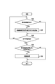
- the secondary estimation process shown in FIG. 11 is executed by the secondary estimation unit 104b as described above.
- the secondary estimation unit 104b acquires the result of the primary estimation process for each channel (hereinafter, referred to as the primary estimation result) from the primary estimation unit 104a.
- the primary estimation result the correspondence relationship between each of the plurality of installation positions indicated by the above-mentioned position information and each of the plurality of radios 20 (radio IDs assigned to) (that is, the plurality of installation positions) Of these, the positions where each of the radios 20 is estimated to be installed) are included.
- the secondary estimation unit 104b executes the following steps S41 and S42 for each of the plurality of installation positions indicated by the position information.
- the installation position to be processed in steps S41 and S42 will be referred to as a target installation position for convenience.
- the secondary estimation unit 104b is a radio that is estimated to be installed at the target installation position based on a predetermined number or more of the primary estimation results for each channel (hereinafter referred to as the corresponding radio). Notation) It is determined whether or not 20 exists (step S41).
- the secondary estimation unit 104b estimates that the corresponding radio 20 is installed at the target installation position (step S42).
- step S42 if it is determined that the corresponding radio 20 does not exist (NO in step S41), the process of step S42 is not executed.
- step S43 it is determined whether or not the processes of steps S41 and S42 have been executed for all the installation positions indicated by the position information.
- step S43 If it is determined that the process has not been executed for all the installation positions (NO in step S43), the process returns to step S41 described above and the process is repeated. In this case, the processes of steps S41 and S42 are executed with the installation position where the process has not been executed as the target installation position.
- the secondary estimation unit 104b has determined that the corresponding radio 20 does not exist (that is, the plurality of radios 20). It is determined whether or not there is an installation position (which is not presumed that the specific radio 20 is installed) (step S44).
- step S44 When it is determined that there is no installation position where it is determined that the corresponding radio 20 does not exist (NO in step S44), the radio 20 installed at each installation position is specified (estimated). Processing is terminated.
- step S44 when it is determined that there is an installation position where it is determined that the corresponding radio 20 does not exist (YES in step S44), the re-estimation process is executed for the installation position (step S45). The details of the re-estimation process will be described later.
- the radios 20 estimated to be installed at the target installation position based on a predetermined number or more of the primary estimation results for each channel are installed at the target installation position.
- the radio 20 that is most presumed to be installed at the target installation position in the primary estimation results for each channel is the relevant one. It may be presumed that it is installed at the target installation position.
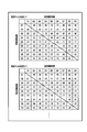
- the secondary estimation process shown in FIG. 11 described above will be specifically described with reference to FIG. 12.
- the plurality of installation positions indicated by the position information are the installation positions P1 to P6, and the plurality of radios 20 are the radios D1 to D6.
- the propagation characteristics are measured in the channels indicated by each of the measurement channel numbers 1 to 3 and the primary estimation result for each of the channels is acquired.
- each of the installation positions P1 to P6 is assigned to the radios D1, D2, D3, D4, D5, and D6 (). ) Is associated with it.
- the radio D1 is installed at the installation position P1 and the radio D2 is installed at the installation position P2 in the primary estimation process in the channel indicated by the measurement channel number 1.
- the radio D3 is installed at the installation position P3, the radio D4 is installed at the installation position P4, the radio D5 is installed at the installation position P5, and the radio D6 is installed at the installation position P6. It is shown that it was presumed to be installed in.
- each of the installation positions P1 to P6 is associated with the radios D1, D2, D6, D3, D4, and D5 (radio IDs assigned to), respectively. ing.
- the radio D1 is installed at the installation position P1 and the radio D2 is installed at the installation position P2 in the primary estimation process in the channel indicated by the measurement channel number 2.
- the radio D6 is installed at the installation position P3, the radio D3 is installed at the installation position P4, the radio D4 is installed at the installation position P5, and the radio D5 is installed at the installation position P6. It is shown that it was presumed to be installed in.
- each of the installation positions P1 to P6 is associated with the radios D1, D5, D3, D2, D6, and D4 (radio IDs assigned to), respectively. ing.
- the radio D1 is installed at the installation position P1 and the radio D5 is installed at the installation position P2 in the primary estimation process in the channel indicated by the measurement channel number 3.
- the radio D3 is installed at the installation position P3, the radio D2 is installed at the installation position P4, the radio D6 is installed at the installation position P5, and the radio D4 is installed at the installation position P6. It is shown that it was presumed to be installed in.
- the installation position P1 is set as the target installation position, and the installation position is obtained in a predetermined number or more of the three primary estimation results (measurement channel numbers 1 to 3). It is determined whether or not there is a radio (corresponding radio) presumed to be installed in P1.
- the radio D1 is installed at the installation position P1 in all three primary estimation results, so that the secondary estimation unit 104b , It is estimated that the radio D1 corresponds to the corresponding radio and that the radio D1 is installed at the installation position P1 as a secondary estimation result.
- the installation position P2 as the target installation position, it is estimated that the installation position P2 is installed in the installation position P2 based on the predetermined number or more of the three primary estimation results (measurement channel numbers 1 to 3). It is determined whether or not the radio (corresponding radio) exists.
- the radio D2 is installed at the installation position P2 in the two primary estimation results (measurement channel numbers 1 and 2) out of the three primary estimation results.
- the secondary estimation unit 104b estimates that the radio D2 corresponds to the corresponding radio and that the radio D2 is installed at the installation position P2 as a secondary estimation result.
- the installation position P3 is installed at the installation position P3 based on the predetermined number or more of the three primary estimation results (measurement channel numbers 1 to 3) with the installation position P3 as the target installation position. Whether or not a radio (corresponding radio) exists is determined.
- the radio D3 is installed at the installation position P3 in the two primary estimation results (measurement channel numbers 1 and 3) out of the three primary estimation results.
- the secondary estimation unit 104b estimates that the radio D3 corresponds to the corresponding radio and that the radio D3 is installed at the installation position P3 as a result of the secondary estimation.
- the installation position P4 as the target installation position, it is estimated that the installation position P4 is installed in the primary estimation results of a predetermined number or more among the three primary estimation results (measurement channel numbers 1 to 3). It is determined whether or not the radio (corresponding radio) exists.
- the radios estimated to be installed at the installation position P4 in the three primary estimation results are the radios D4, D3 and D2, respectively, and a predetermined number (here, here). 2) Based on the above primary estimation results, it is determined that there is no radio presumed to be installed at the installation position P4. Similarly, it is determined that the corresponding radio does not exist at the installation positions P5 and P6.
- step S45 If it is determined in the secondary estimation process that the corresponding radio does not exist at the installation positions P4 to P6 as described above, the re-estimation process is executed in step S45 shown in FIG.
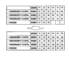
- FIG. 13 shows the processing result of the secondary estimation process before the re-estimation process described in FIG. 12 is executed. That is, as a result of executing the secondary estimation process (process of steps S41 to S44 shown in FIG. 11) after the primary estimation result (measurement channel numbers 1 to 3) is acquired, each of the installation positions P1 to P3 is wireless. It is assumed that the machines D1 to D3 are installed, and it is determined that the corresponding radio does not exist at the installation positions P4 to P6.
- the primary estimation process is executed again for each channel in consideration of the fact that the radios D1 to D3 are estimated to be installed in each of the installation positions P1 to P3 as described above. ..
- evaluation values are obtained for various combinations (hypotheses) of each of the installation positions P1 to P6 and each of the radios D1 to D6. Is calculated, and the position where the radios D1 to D6 are installed is estimated based on the combination in which the highest evaluation value is calculated.
- the secondary estimation process is performed. Based on the combination for which the highest evaluation value was calculated among the combinations that satisfy the correspondence relationship (P1-D1, P2-D2, P3-D3) between the installation positions P1 to P3 and the radios D1 to D3 already estimated in The position where each of the radios D1 to D6 is installed is estimated.
- the primary estimation process does not have to be executed again for the channel indicated by the measurement channel number 1 that already satisfies the correspondence between the installation positions P1 to P3 already estimated in the secondary estimation process and the radios D1 to D3. May be good.
- FIG. 13 shows an example of the result (primary estimation result) in which the primary estimation process is executed again in the re-estimation process.
- each of the installation positions P1 to P6 is associated with the radios D1, D2, D3, D4, D5, and D6, respectively. There is. Further, in the primary estimation result (measurement channel number 2), each of the installation positions P1 to P6 is associated with the radios D1, D2, D3, D5, D4, and D6. Further, in the primary estimation result (measurement channel number 3), each of the installation positions P1 to P6 is associated with the radios D1, D2, D3, D4, D5, and D6.
- the above-mentioned secondary estimation process (process shown in FIG. 11) is executed again based on the result of the primary estimation process being executed again in this way.
- the radio D4 is installed at the installation position P4, and the radio D5 is installed at the installation position P5. It can be estimated that the radio D6 is installed at the installation position P6.
- the secondary estimation process may not be executed again.
- the evaluation value for example, the correlation coefficient
- the primary estimation result having the highest evaluation value may be selected (adopted), and the positions where each of the radios D1 to D6 are installed may be estimated based on the selected primary estimation result.
- the secondary estimation process is re-executed based on the result of the primary estimation process re-executed in the re-estimation process, it is installed at the installation positions P4 to P5.
- the radio D4 is installed at the installation position P4 based on the primary estimation result (measurement channel number 1) with a high evaluation value. It can be estimated that the radio D5 is installed at the position P5 and the radio D6 is installed at the installation position P6.
- the primary estimation process is executed again using all the characteristic information (propagation characteristics between the radios D1 to D6) stored in the characteristic information storage unit 102. For example, re-estimation is performed. If it is estimated that the radios D1 to D3 are installed at the installation positions P1 to P3 before the processing is executed, the position information indicating the installation positions P4 to P6 and the installation position are not estimated.
- the primary estimation process in each channel may be executed using only the characteristic information including the propagation characteristics between the radios D4 to D6. In other words, in this primary estimation process, a process of estimating the position where each of the radios D4 to D6 is installed is executed from the installation positions P4 to P6. Even in the case of such a configuration, it is possible to obtain an estimation result as described in FIG. 13, for example.
- the position information stored in the position information storage unit 103 the first characteristic information obtained from the first propagation characteristic in the first channel of the first radio 20, and the second characteristic information.
- First estimation result (first channel) of the position where each of the first and second radios 20 is installed based on the third characteristic information obtained from the third propagation characteristic in the first channel of the radio 20.
- the position information, the second characteristic information obtained from the second propagation characteristic in the second channel of the first radio 20, and the fourth in the second channel of the second radio 20 is acquired.
- the positions where each of the first and second radios 20 are installed are estimated based on the above-mentioned first and second estimation results.
- the same radio 20 among the plurality of radios 20 is installed at the same position among the first and second installation positions in the predetermined number or more of the first and second estimation results. If it is presumed, it is presumed that the radio 20 is installed at the position. In addition, it is said that the specific radio 20 among the plurality of radios 20 most presumed to be installed in the first installation position in the first and second estimation results is installed in the first installation position. A specific radio 20 among a plurality of radios 20 estimated to be installed at the second installation position in the first and second estimation results is installed at the second installation position. May be presumed.
- the positions where each of the first and second radios 20 are installed in consideration of each of the first estimation result in the first channel and the second estimation result in the second channel In order to estimate the position, the influence of the outliers of the propagation characteristics is compared with the case where the position is estimated using the feature amount of the propagation characteristics measured in each of the plurality of channels as in the first embodiment described above. It is difficult to receive and can be expected to improve the estimation accuracy.
- the first and second radios 20 installed at each of the third installation positions of the first and second installation positions are estimated based on the first and second estimation results. If the first and second radios 20 installed in each of the fourth installation positions of the first and second installation positions cannot be estimated, the first and second radios 20 are installed from the fourth installation positions. A re-estimation process for re-estimating the position where each of the second radios 20 is installed is executed.
- the position information stored in the position information storage unit 103 the first characteristic information obtained from the first propagation characteristic of the first radio, and the second radio.
- the first of the fourth installation positions Based on the third characteristic information obtained from the three propagation characteristics and the first and second radios 20 estimated to be installed at each of the third installation positions, the first of the fourth installation positions
- the third estimation result (primary estimation result in the first channel) of the position where each of the second radio is installed is acquired, and the second propagation characteristic obtained from the position information and the second propagation characteristic of the first radio is obtained.
- the 4th characteristic information obtained from the 4th propagation characteristic of the 2nd radio, and the 1st and 2nd radios estimated to be installed at each of the 3rd installation positions Based on the 2 characteristic information, the 4th characteristic information obtained from the 4th propagation characteristic of the 2nd radio, and the 1st and 2nd radios estimated to be installed at each of the 3rd installation positions.
- the fourth estimation result (primary estimation result in the second channel) of the position where each of the first and second radios of the fourth installation position is installed is acquired.
- the positions where the first and second radios 20 are installed are re-estimated from the fourth installation positions based on the third and fourth estimation results acquired in this way.
- the re-estimation process from the fourth installation position based on the third or fourth estimation result selected based on the first evaluation value for the third estimation result and the second evaluation value for the fourth estimation result.
- the positions where the first and second radios 20 are installed may be estimated again. According to such a configuration, it is not necessary to re-execute the secondary estimation process in the estimation process, so that the processing load on the electronic device 10 can be reduced.
- the position information indicating each of the fourth installation positions and the characteristics of the radios 20 other than the first and second radios 20 estimated to be installed at each of the third installation positions Based on the information, the position where the radio 20 is installed is estimated again from the fourth installation position. According to such a configuration, it is not necessary to execute the re-estimation process using all the characteristic information stored in the characteristic information storage unit 102, so that the processing load in the electronic device 10 can be reduced.
Landscapes
- Engineering & Computer Science (AREA)
- Physics & Mathematics (AREA)
- General Physics & Mathematics (AREA)
- Radar, Positioning & Navigation (AREA)
- Remote Sensing (AREA)
- Computer Networks & Wireless Communication (AREA)
- Signal Processing (AREA)
- Electromagnetism (AREA)
- Mobile Radio Communication Systems (AREA)
- Position Fixing By Use Of Radio Waves (AREA)
Abstract
La présente invention concerne un appareil électronique qui comprend, selon un mode de réalisation, un moyen de stockage, un moyen de réception et un moyen d'estimation. Le moyen de stockage stocke des informations de position indiquant des première et seconde positions d'installation d'une pluralité de dispositifs. Le moyen de réception reçoit des informations de caractéristique d'un premier dispositif, parmi la pluralité de dispositifs, qui sont déterminées à partir d'une première caractéristique de propagation dans un premier canal du premier dispositif et d'une deuxième caractéristique de propagation dans un second canal du premier dispositif, et des informations de caractéristique d'un second dispositif, parmi la pluralité de dispositifs, qui sont déterminées à partir d'une troisième caractéristique de propagation dans un premier canal du second dispositif et d'une quatrième caractéristique de propagation dans un second canal du second dispositif. Le moyen d'estimation estime des positions où les premier et second dispositifs sont respectivement installés à partir des première et seconde positions d'installation sur la base des informations de position, des informations de caractéristique du premier dispositif et des informations de caractéristique du second dispositif.
Priority Applications (4)
| Application Number | Priority Date | Filing Date | Title |
|---|---|---|---|
| PCT/JP2019/024165 WO2020255271A1 (fr) | 2019-06-18 | 2019-06-18 | Appareil électronique et procédé associé |
| JP2021500971A JP7053081B2 (ja) | 2019-06-18 | 2019-06-18 | 電子装置及び方法 |
| US17/194,061 US11959994B2 (en) | 2019-06-18 | 2021-03-05 | Electronic apparatus, method, and electronic system |
| JP2022042688A JP7242937B2 (ja) | 2019-06-18 | 2022-03-17 | 電子装置及び方法 |
Applications Claiming Priority (1)
| Application Number | Priority Date | Filing Date | Title |
|---|---|---|---|
| PCT/JP2019/024165 WO2020255271A1 (fr) | 2019-06-18 | 2019-06-18 | Appareil électronique et procédé associé |
Related Child Applications (1)
| Application Number | Title | Priority Date | Filing Date |
|---|---|---|---|
| US17/194,061 Continuation US11959994B2 (en) | 2019-06-18 | 2021-03-05 | Electronic apparatus, method, and electronic system |
Publications (1)
| Publication Number | Publication Date |
|---|---|
| WO2020255271A1 true WO2020255271A1 (fr) | 2020-12-24 |
Family
ID=74037063
Family Applications (1)
| Application Number | Title | Priority Date | Filing Date |
|---|---|---|---|
| PCT/JP2019/024165 Ceased WO2020255271A1 (fr) | 2019-06-18 | 2019-06-18 | Appareil électronique et procédé associé |
Country Status (3)
| Country | Link |
|---|---|
| US (1) | US11959994B2 (fr) |
| JP (1) | JP7053081B2 (fr) |
| WO (1) | WO2020255271A1 (fr) |
Cited By (1)
| Publication number | Priority date | Publication date | Assignee | Title |
|---|---|---|---|---|
| JP2025016564A (ja) * | 2021-05-12 | 2025-02-04 | コグニティヴ システムズ コーポレイション | Wi-Fiセンシングのための時間領域チャネル表現情報のためのシステム及び方法 |
Families Citing this family (5)
| Publication number | Priority date | Publication date | Assignee | Title |
|---|---|---|---|---|
| WO2020255272A1 (fr) | 2019-06-18 | 2020-12-24 | 株式会社 東芝 | Appareil électronique et procédé |
| WO2021176565A1 (fr) | 2020-03-03 | 2021-09-10 | 株式会社 東芝 | Dispositif électronique, procédé, programme et système de communication |
| WO2021186566A1 (fr) | 2020-03-17 | 2021-09-23 | 株式会社 東芝 | Dispositif électronique, procédé, programme et système de communication |
| JP2023019305A (ja) | 2021-07-29 | 2023-02-09 | 株式会社東芝 | 電子装置、電子システム、及び方法 |
| JP2023019304A (ja) | 2021-07-29 | 2023-02-09 | 株式会社東芝 | 電子装置、電子システム、及び方法 |
Citations (1)
| Publication number | Priority date | Publication date | Assignee | Title |
|---|---|---|---|---|
| JP2012173070A (ja) * | 2011-02-18 | 2012-09-10 | Fujitsu Ltd | 移動端末位置推定装置、移動端末位置推定方法及び電波環境指標算出方法 |
Family Cites Families (19)
| Publication number | Priority date | Publication date | Assignee | Title |
|---|---|---|---|---|
| US6473038B2 (en) | 2001-01-05 | 2002-10-29 | Motorola, Inc. | Method and apparatus for location estimation |
| US7295119B2 (en) | 2003-01-22 | 2007-11-13 | Wireless Valley Communications, Inc. | System and method for indicating the presence or physical location of persons or devices in a site specific representation of a physical environment |
| US7092726B2 (en) | 2003-12-29 | 2006-08-15 | Motorola, Inc. | Method and system for determining a location using a plurality of selected initial location estimates |
| JP2008224489A (ja) | 2007-03-14 | 2008-09-25 | Yamatake Corp | 位置推定装置 |
| US9807849B2 (en) | 2008-09-10 | 2017-10-31 | Enlighted, Inc. | Automatically commissioning lighting controls using sensing parameters of the lighting controls |
| US8237612B2 (en) | 2010-02-24 | 2012-08-07 | Microsoft Corporation | Inferring beacon positions based on spatial relationships |
| US8311548B2 (en) | 2010-03-24 | 2012-11-13 | Honeywell International Inc. | Automatic association of wireless devices to point names |
| US20150103681A1 (en) | 2013-10-16 | 2015-04-16 | Jdsu Uk Limited | Method and apparatus for deriving signal strength attenuation characteristic values |
| CN103634810B (zh) | 2013-12-24 | 2017-04-12 | 英国Ranplan无线网络设计公司 | 一种室内无线网络覆盖问题区域定位的方法 |
| JP6517623B2 (ja) | 2015-08-04 | 2019-05-22 | 株式会社東芝 | 無線機器配置推定装置、無線機器配置推定方法、無線機器配置推定プログラム |
| KR102489490B1 (ko) * | 2015-08-13 | 2023-01-17 | 삼성전자주식회사 | 무선 통신 시스템에서 단말의 위치를 추정하기 위한 장치 및 방법 |
| US9846220B2 (en) | 2015-08-19 | 2017-12-19 | Locix, Inc. | Systems and methods for determining locations of wireless sensor nodes in a network architecture having mesh-based features for localization |
| JP6750273B2 (ja) | 2016-03-30 | 2020-09-02 | 沖電気工業株式会社 | 位置推定装置、位置推定プログラム、監視装置及び状態監視システム |
| WO2018027239A1 (fr) | 2016-08-05 | 2018-02-08 | Neonic Corporation | Système et procédé de localisation de dispositif sans fil |
| EP3306337A1 (fr) * | 2016-10-10 | 2018-04-11 | Fraunhofer Gesellschaft zur Förderung der Angewand | Localisation d'équipement utilisateur dans un réseau de communication mobile |
| JPWO2018123970A1 (ja) | 2016-12-27 | 2019-10-31 | 株式会社村田製作所 | 位置推定システム及び位置推定方法 |
| KR102129400B1 (ko) | 2017-01-23 | 2020-07-02 | 한국과학기술원 | 라디오 맵 구축 방법 |
| US10579963B2 (en) | 2017-09-28 | 2020-03-03 | Intel Corporation | Self-adaptive inventory and fixture tracking |
| WO2020255272A1 (fr) | 2019-06-18 | 2020-12-24 | 株式会社 東芝 | Appareil électronique et procédé |
-
2019
- 2019-06-18 WO PCT/JP2019/024165 patent/WO2020255271A1/fr not_active Ceased
- 2019-06-18 JP JP2021500971A patent/JP7053081B2/ja active Active
-
2021
- 2021-03-05 US US17/194,061 patent/US11959994B2/en active Active
Patent Citations (1)
| Publication number | Priority date | Publication date | Assignee | Title |
|---|---|---|---|---|
| JP2012173070A (ja) * | 2011-02-18 | 2012-09-10 | Fujitsu Ltd | 移動端末位置推定装置、移動端末位置推定方法及び電波環境指標算出方法 |
Non-Patent Citations (1)
| Title |
|---|
| YONEZAWA, YUKI ET AL: "Wireless Equipment Self-PositioningEstimation without Using Anchor Nodes", IPSJ SYMPOSIUM SERIES: MULTIMEDIA, DISTRIBUTED, COOPERATIVE AND MOBILE SYMPOSIUM, vol. 2016, no. 1, 25 August 2016 (2016-08-25), pages 123 - 128 * |
Cited By (2)
| Publication number | Priority date | Publication date | Assignee | Title |
|---|---|---|---|---|
| JP2025016564A (ja) * | 2021-05-12 | 2025-02-04 | コグニティヴ システムズ コーポレイション | Wi-Fiセンシングのための時間領域チャネル表現情報のためのシステム及び方法 |
| JP7785148B2 (ja) | 2021-05-12 | 2025-12-12 | コグニティヴ システムズ コーポレイション | Wi-Fiセンシングのための時間領域チャネル表現情報のためのシステム及び方法 |
Also Published As
| Publication number | Publication date |
|---|---|
| US20210190927A1 (en) | 2021-06-24 |
| JP7053081B2 (ja) | 2022-04-12 |
| JPWO2020255271A1 (ja) | 2021-09-30 |
| US11959994B2 (en) | 2024-04-16 |
Similar Documents
| Publication | Publication Date | Title |
|---|---|---|
| JP7053081B2 (ja) | 電子装置及び方法 | |
| US12028018B2 (en) | Electronic apparatus for determining correspondence between devices and positions at which devices are located using propagation characteristic of wireless communication between devices, and method, and electronic system for same | |
| JP6517623B2 (ja) | 無線機器配置推定装置、無線機器配置推定方法、無線機器配置推定プログラム | |
| JP4973382B2 (ja) | 位置推定方法、及び位置推定システム | |
| JP2009047457A (ja) | 無線測位システム | |
| US20180279078A1 (en) | Confirming work supporting device, confirming work supporting system, and computer program product | |
| AU2020263909B2 (en) | Access control system and method for operating an access control system | |
| US20200217542A1 (en) | Diagnostic method, diagnostic apparatus, diagnostic system, and non-transitory computer readable recording medium storing diagnostic program | |
| EP3677853B1 (fr) | Dispositif de commande de système de climatisation | |
| JP2017227600A (ja) | 無線機器位置推定装置 | |
| US11240860B2 (en) | Run-time system for deployment of indoor positioning systems | |
| JP7170893B2 (ja) | 電子装置、方法、プログラム、および通信システム | |
| US7579990B2 (en) | Method and system for estimating the location of a wireless terminal from a received signal strength | |
| US20210329478A1 (en) | Radio wave strength estimation device, position estimation system, and radio wave strength estimation method | |
| JP7242937B2 (ja) | 電子装置及び方法 | |
| US12498133B2 (en) | Air-conditioning system, management device, air conditioner, sensor data acquisition method, and recording medium | |
| JP2008211482A (ja) | 故障検出方法及び無線通信装置 | |
| JP6385125B2 (ja) | 無線センサネットワーク障害の原因特定方法、原因特定装置及び原因特定プログラム | |
| JP2005195307A (ja) | データ収集方法および中継装置 | |
| JP2006217390A (ja) | 機器管理装置および機器管理方法 | |
| JP7338367B2 (ja) | サーバ及び制御方法 | |
| JP7242935B2 (ja) | 電子装置、方法及びプログラム | |
| JP6555816B2 (ja) | 試験システム | |
| US20200235835A1 (en) | Computer system, method for estimating radio wave propagation characteristic in space, and computer | |
| JP6334486B2 (ja) | 無線通信装置、方法およびプログラム |
Legal Events
| Date | Code | Title | Description |
|---|---|---|---|
| ENP | Entry into the national phase |
Ref document number: 2021500971 Country of ref document: JP Kind code of ref document: A |
|
| 121 | Ep: the epo has been informed by wipo that ep was designated in this application |
Ref document number: 19934197 Country of ref document: EP Kind code of ref document: A1 |
|
| NENP | Non-entry into the national phase |
Ref country code: DE |
|
| 122 | Ep: pct application non-entry in european phase |
Ref document number: 19934197 Country of ref document: EP Kind code of ref document: A1 |