WO2020255285A1 - Palan, dispositif d'ascenseur l'utilisant et dispositif de poulie - Google Patents
Palan, dispositif d'ascenseur l'utilisant et dispositif de poulie Download PDFInfo
- Publication number
- WO2020255285A1 WO2020255285A1 PCT/JP2019/024226 JP2019024226W WO2020255285A1 WO 2020255285 A1 WO2020255285 A1 WO 2020255285A1 JP 2019024226 W JP2019024226 W JP 2019024226W WO 2020255285 A1 WO2020255285 A1 WO 2020255285A1
- Authority
- WO
- WIPO (PCT)
- Prior art keywords
- sheave
- hoisting machine
- spindle
- disc
- peripheral surface
- Prior art date
- Legal status (The legal status is an assumption and is not a legal conclusion. Google has not performed a legal analysis and makes no representation as to the accuracy of the status listed.)
- Ceased
Links
Images



Classifications
-
- B—PERFORMING OPERATIONS; TRANSPORTING
- B66—HOISTING; LIFTING; HAULING
- B66B—ELEVATORS; ESCALATORS OR MOVING WALKWAYS
- B66B11/00—Main component parts of lifts in, or associated with, buildings or other structures
- B66B11/04—Driving gear ; Details thereof, e.g. seals
- B66B11/08—Driving gear ; Details thereof, e.g. seals with hoisting rope or cable operated by frictional engagement with a winding drum or sheave
-
- B—PERFORMING OPERATIONS; TRANSPORTING
- B66—HOISTING; LIFTING; HAULING
- B66B—ELEVATORS; ESCALATORS OR MOVING WALKWAYS
- B66B7/00—Other common features of elevators
- B66B7/06—Arrangements of ropes or cables
Definitions
- the present invention relates to a hoisting machine equipped with a replaceable sheave, an elevator device using the hoisting machine, and a pulley device.
- Patent Document 1 is known as a background technology for hoisting machines equipped with replaceable sheaves.
- claim 1 "a fixed shaft cantilevered and supported by a fixed frame in a hoistway, a rotating frame rotatably supported by the fixed shaft, and the rotating frame and the fixed frame.
- a motor configured between the two, a rope wheel that is detachably attached to the outer surface of the rotating frame and around which a rope for raising and lowering a car is wound, and a rope wheel that is projected from the outer surface of the rotating frame.
- a hoisting machine for an elevator that includes a bearing holding portion to which a mounting hole for a rope wheel is mounted, and the rope wheel and the bearing holding portion are formed concentrically with the axis of the fixed shaft.
- a hoisting machine for an elevator characterized in that the inner surface of the hole and the outer surface of the bearing holding portion are formed in a tapered shape at the same angle, is described.
- Patent Document 1 As is clear from FIGS. 1 and 6 of the same document, an old sheave with a worn groove from the free end side of the cantilever support shaft (reference numeral 28) of the hoisting machine (reference numeral 15) (reference numeral 15). Since the reference numeral 32) can be removed and a new sheave can be attached, even if the sheave is integrally molded, the replacement work is easy.
- an object of the present invention is to provide a hoisting machine that can easily replace the sheave without removing the pedestal even if the shaft of the sheave is supported by both sides.
- the hoisting machine of the present invention includes a disk fixed to the outer peripheral surface of the spindle, a pedestal that supports one end of the spindle, a housing that supports the other end of the spindle, and the above.
- the hoisting machine is a hoisting machine that is formed by combining a plurality of arc-shaped sheaves to form an annular shape as a whole.
- the sheave can be easily replaced without removing the pedestal even if the shaft of the sheave is supported by both sides.
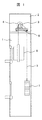
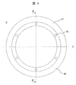
- FIG. 4 Schematic diagram showing the configuration of the elevator device of one embodiment Enlarged side view of the main part of the hoisting machine Cross-sectional view taken along the line AA shown in FIG. An enlarged cross-sectional view of the connecting portion between the sheave and the connecting portion in the hoisting machine shown in FIG. Front view of the sheave shown in FIG. 4 as viewed from the pedestal side Cross-sectional view taken along line BB shown in FIG.
- FIG. 1 is a schematic view showing the configuration of the elevator device of this embodiment.
- the elevator device has a hoistway 1 formed in the building structure and a machine room 2 formed above the hoistway 1.
- a hoisting machine 3 and a pulley 8 are arranged in the machine room 2, and a main rope 5 (rope) is wound around two pulleys (a sheave 4 and a pulley 8 of the hoisting machine 3).
- one end of the main rope 5 is connected to the car 6 arranged in the hoistway 1, and the other end of the main rope 5 is connected to the balance weight 7 arranged in the hoistway 1.
- the sheave 4 rotates to wind up the main rope 5, and the car 6 and the counterweight 7 are lifted and lowered in a sliding manner while being guided by a guide rail (not shown).
- FIG. 2 is an enlarged side view of a main part of the hoisting machine 3.
- the hoisting machine 3 has a base 30 mounted on the floor of the machine room 2, and a pedestal 31 is fixed to the upper surface of the base 30, and the pedestal 31 fixes the hoisting machine 3 to the hoisting machine 3.
- One end (tip side) of the main shaft 32 is rotatably supported.
- a disc 33 is fixed to the outer peripheral surface of the spindle 32, and brake devices 34A and 34B for applying a braking force to the rotating disc 33 are arranged above the hoisting machine 3.
- FIG. 3 is a cross-sectional view taken along the line AA of FIG.
- one end (tip side) of the spindle 32 of the hoisting machine 3 is rotatably supported by the bearing 35A on the pedestal 31 side, and the other end is rotatably supported by the bearing 35B on the housing 36 side.
- a boss portion 32a is formed on the outer peripheral surface of the main shaft 32 at the center in the axial direction, and the disc 33 is fitted on the outer peripheral surface of the boss portion 32a.
- a sheave 4 is detachably attached to the pedestal 31 side of the disc 33 by a plurality of bolts 4a.
- the housing 36 is formed with an annular storage portion 36a so as to surround the outer periphery of the other end side of the main shaft 32, and an annular stator 37 is fixed to the inner peripheral side of the storage portion 36a. ..
- a rotor 38 projecting to the outer peripheral side in the storage portion 36a is fixed to the housing 36 side of the disk 33.
- the stator 37 and the rotor 38 are arranged to face each other with a predetermined gap, and both of them form a motor for driving the hoisting machine 3.
- the stator 37 is composed of, for example, a laminated electromagnetic steel plate and a stator coil wound around the laminated electromagnetic steel plate, and the rotor 38 is, for example, spaced at a predetermined interval along the circumferential direction. It is composed of a plurality of fixed magnets.
- FIG. 4 is an enlarged cross-sectional view of the connecting portion between the disc 33 and the sheave 4.
- the sheave 4 having a groove 4f around which the main rope 5 is wound is fitted into the joint 33a of the disc 33 from the pedestal 31 side (right side in FIG. 4), and the bolt of the sheave 4 is fitted.
- the structure is such that the bolt 4a inserted into the through hole 4e of the fixing portion 4d is fastened to the screw hole 33d of the disc 33.
- a tapered fitting surface 4b whose inner diameter gradually increases from the right side to the left side of FIG. 4 is formed on the inner peripheral surface of the sheave 4.
- a reverse taper fitting surface 33c whose outer diameter gradually increases from the right side to the left side is formed on the outer peripheral surface of the coupling portion 33a so as to match this.
- FIG. 5 is a front view of the sheave 4 as viewed from the pedestal 31 side
- FIG. 6 is a cross-sectional view taken along the line BB of FIG.
- the circumferential direction of the sheave 4 of this embodiment is divided into a semi-annular sheave 41 on the upper side of the dividing surface C and a semi-annular sheave 42 on the lower side of the dividing surface C.
- a circular structure is formed as a whole.
- a plurality of the above-mentioned through holes 4e are formed at substantially equal intervals in the circumferential direction on the inner peripheral side of the semi-annular sheaves 41 and 42.
- the sheave 4 of the present embodiment can be divided into the semi-annular sheaves 41 and 42, when the old sheave 4 whose groove 4f is worn is replaced, the bolt 4a on the semi-annular sheave 41 side is replaced.
- the semi-annular sheave 41 can be easily removed without removing the pedestal 31 by removing all of the above, and the semi-annular sheave 41 can be easily removed without removing the pedestal 31 by removing all the bolts 4a on the semi-annular sheave 42 side.
- the 42 can be easily removed.
- the new sheave 4 can be easily attached by roughly reversing the procedure.
- the new sheave 4 also has a tapered fitting surface 4b that is fitted to the reverse taper fitting surface 33c of the joint portion 33a, and also has a presser that is fitted into the fitting recess 33b of the joint portion 33a. Since it has a portion 4c, it can be easily positioned or temporarily held. After that, a plurality of bolts 4a are tightened, but since the position of the bolts 4a is located above the upper end of the pedestal 31, the tightening can be easily performed. Further, if the spindle 32 can be rotated, the position of the bolt 4a between the sheave 4 and the coupling portion 33a can be adjusted to a position where it is easy to work while rotating the spindle 32.
- a tapered fitting surface 4b is formed on the semi-annular sheaves 41 and 42, and a reverse tapered fitting surface is received on the tapered fitting surface 4b of each of the semi-annular sheaves 41 and 42 fitted in the joint 33a.
- a fitting recess 33b is formed so that the holding portion 4c is formed at the tip of the semi-annular sheaves 41 and 42 on the fitting side to the fitting portion 33a, and the holding portion 4c is fitted into the connecting portion 33a. Is forming.
- FIGS. 5 and 6 semi-annular sheaves 41 and 42 having the same shape divided into two in the circumferential direction are illustrated, but each semi-annular sheave does not have to have the same shape, and three or more.
- An annular sheave 4 may be formed by combining the arc-shaped sheaves of the above.
- the elevator device has a configuration similar to that of the sheave 4 in addition to the hoisting machine 3.
- the configuration of the pulley 8 can be separated like the sheave 4 illustrated in FIGS. 5 and 6. May be.
- the old semi-annular sheaves 41 and 42 can be easily removed by simply removing the bolt 4a without removing the pedestal 31. After that, new semi-annular sheaves 41 and 41 can be easily attached.
- the present invention is not limited to the above-mentioned examples, and includes various modifications.
- the above-described examples have been described in detail in order to explain the present invention in an easy-to-understand manner, and are not necessarily limited to those having all the described configurations. It is also possible to replace a part of the configuration of one embodiment with the configuration of another embodiment, and it is also possible to add the configuration of another embodiment to the configuration of one embodiment. In addition, it is possible to add, delete, or replace a part of the configuration of each embodiment with another configuration.
Landscapes
- Engineering & Computer Science (AREA)
- Civil Engineering (AREA)
- Mechanical Engineering (AREA)
- Structural Engineering (AREA)
- Cage And Drive Apparatuses For Elevators (AREA)
Abstract
L'invention concerne un palan conçu pour permettre un travail de remplacement simple lors du remplacement d'une réa en raison de l'usure d'une gorge. Dans ce but, ledit palan est pourvu de : un disque fixé à la surface circonférentielle externe d'un arbre principal ; un socle destiné à supporter une extrémité de l'arbre principal ; un logement destiné à supporter l'autre extrémité de l'arbre principal ; une réa fixée à un côté de surface du disque et ayant une section gorge sur sa surface circonférentielle externe ; un rotor fixé à l'autre côté de surface du disque ; et un stator fixé au logement de manière à faire face au rotor, la réa étant conçue pour avoir une forme globale annulaire par combinaison d'une pluralité de réas en forme d'arc.
Priority Applications (1)
| Application Number | Priority Date | Filing Date | Title |
|---|---|---|---|
| PCT/JP2019/024226 WO2020255285A1 (fr) | 2019-06-19 | 2019-06-19 | Palan, dispositif d'ascenseur l'utilisant et dispositif de poulie |
Applications Claiming Priority (1)
| Application Number | Priority Date | Filing Date | Title |
|---|---|---|---|
| PCT/JP2019/024226 WO2020255285A1 (fr) | 2019-06-19 | 2019-06-19 | Palan, dispositif d'ascenseur l'utilisant et dispositif de poulie |
Publications (1)
| Publication Number | Publication Date |
|---|---|
| WO2020255285A1 true WO2020255285A1 (fr) | 2020-12-24 |
Family
ID=74040348
Family Applications (1)
| Application Number | Title | Priority Date | Filing Date |
|---|---|---|---|
| PCT/JP2019/024226 Ceased WO2020255285A1 (fr) | 2019-06-19 | 2019-06-19 | Palan, dispositif d'ascenseur l'utilisant et dispositif de poulie |
Country Status (1)
| Country | Link |
|---|---|
| WO (1) | WO2020255285A1 (fr) |
Citations (6)
| Publication number | Priority date | Publication date | Assignee | Title |
|---|---|---|---|---|
| JPS59195248U (ja) * | 1983-06-13 | 1984-12-25 | 三菱電機株式会社 | エレベ−タ用巻上装置の綱車 |
| WO2002064483A1 (fr) * | 2001-02-13 | 2002-08-22 | Mitsubishi Denki Kabushiki Kaisha | Rea d'entrainement d'ascenseur |
| WO2014065183A1 (fr) * | 2012-10-22 | 2014-05-01 | 株式会社Ihi | Moufle |
| JP2016204086A (ja) * | 2015-04-20 | 2016-12-08 | 株式会社日立製作所 | エレベータ装置 |
| JP2018039579A (ja) * | 2016-09-05 | 2018-03-15 | 三菱電機ビルテクノサービス株式会社 | エレベーターの綱車、及び綱車の綱溝の取替方法 |
| JP2018177415A (ja) * | 2017-04-07 | 2018-11-15 | 株式会社日立製作所 | 巻上機およびエレベーター |
-
2019
- 2019-06-19 WO PCT/JP2019/024226 patent/WO2020255285A1/fr not_active Ceased
Patent Citations (6)
| Publication number | Priority date | Publication date | Assignee | Title |
|---|---|---|---|---|
| JPS59195248U (ja) * | 1983-06-13 | 1984-12-25 | 三菱電機株式会社 | エレベ−タ用巻上装置の綱車 |
| WO2002064483A1 (fr) * | 2001-02-13 | 2002-08-22 | Mitsubishi Denki Kabushiki Kaisha | Rea d'entrainement d'ascenseur |
| WO2014065183A1 (fr) * | 2012-10-22 | 2014-05-01 | 株式会社Ihi | Moufle |
| JP2016204086A (ja) * | 2015-04-20 | 2016-12-08 | 株式会社日立製作所 | エレベータ装置 |
| JP2018039579A (ja) * | 2016-09-05 | 2018-03-15 | 三菱電機ビルテクノサービス株式会社 | エレベーターの綱車、及び綱車の綱溝の取替方法 |
| JP2018177415A (ja) * | 2017-04-07 | 2018-11-15 | 株式会社日立製作所 | 巻上機およびエレベーター |
Similar Documents
| Publication | Publication Date | Title |
|---|---|---|
| KR100740390B1 (ko) | 권상기 및 권상기 본체의 제조 방법 | |
| CN101423167A (zh) | 电梯以及该电梯使用的卷扬机和电动机 | |
| JP2016037336A (ja) | エレベータ装置およびエレベータ装置用巻上機 | |
| JP2016034872A (ja) | エレベータ用巻上機 | |
| JP5238473B2 (ja) | エレベータ用巻上機及びその駆動モータ | |
| JP2004338915A (ja) | エレベータ用巻上機 | |
| JP7032291B2 (ja) | 巻上機及びエレベーター | |
| KR101611112B1 (ko) | 엘리베이터용 권상기 및 엘리베이터용 권상기의 제조방법 | |
| JP2018177415A (ja) | 巻上機およびエレベーター | |
| JPS5958261A (ja) | 駆動用シ−ブ | |
| JPWO2005068338A1 (ja) | エレベータ用巻上機 | |
| WO2020255285A1 (fr) | Palan, dispositif d'ascenseur l'utilisant et dispositif de poulie | |
| JP4499496B2 (ja) | エレベータ用巻上機 | |
| JP5591767B2 (ja) | 薄型巻上機およびエレベータ装置 | |
| JP2013136444A (ja) | エレベータ用巻上機 | |
| JP2020075794A (ja) | 巻上機及びエレベーター | |
| CN109205443B (zh) | 卷扬机以及电梯 | |
| JP7098036B1 (ja) | エレベータの巻上機 | |
| JP6606029B2 (ja) | エレベータ用巻上機、および、エレベータ装置 | |
| WO2021124389A1 (fr) | Appareil de levage et ascenseur | |
| JP5590471B2 (ja) | 巻上機及びエレベータ | |
| JP2018177434A (ja) | エレベーター用巻上機 | |
| KR100790654B1 (ko) | 엘리베이터용 권상기 | |
| JP3787570B2 (ja) | エレベーター装置 | |
| JP2008074590A (ja) | エレベータ用の巻上機 |
Legal Events
| Date | Code | Title | Description |
|---|---|---|---|
| 121 | Ep: the epo has been informed by wipo that ep was designated in this application |
Ref document number: 19933412 Country of ref document: EP Kind code of ref document: A1 |
|
| NENP | Non-entry into the national phase |
Ref country code: DE |
|
| 122 | Ep: pct application non-entry in european phase |
Ref document number: 19933412 Country of ref document: EP Kind code of ref document: A1 |
|
| NENP | Non-entry into the national phase |
Ref country code: JP |