WO2020255325A1 - 管接続部の離脱防止構造 - Google Patents
管接続部の離脱防止構造 Download PDFInfo
- Publication number
- WO2020255325A1 WO2020255325A1 PCT/JP2019/024476 JP2019024476W WO2020255325A1 WO 2020255325 A1 WO2020255325 A1 WO 2020255325A1 JP 2019024476 W JP2019024476 W JP 2019024476W WO 2020255325 A1 WO2020255325 A1 WO 2020255325A1
- Authority
- WO
- WIPO (PCT)
- Prior art keywords
- pipe
- joint ring
- detachment
- receiving port
- insertion port
- Prior art date
- Legal status (The legal status is an assumption and is not a legal conclusion. Google has not performed a legal analysis and makes no representation as to the accuracy of the status listed.)
- Ceased
Links
Images









Classifications
-
- F—MECHANICAL ENGINEERING; LIGHTING; HEATING; WEAPONS; BLASTING
- F16—ENGINEERING ELEMENTS AND UNITS; GENERAL MEASURES FOR PRODUCING AND MAINTAINING EFFECTIVE FUNCTIONING OF MACHINES OR INSTALLATIONS; THERMAL INSULATION IN GENERAL
- F16L—PIPES; JOINTS OR FITTINGS FOR PIPES; SUPPORTS FOR PIPES, CABLES OR PROTECTIVE TUBING; MEANS FOR THERMAL INSULATION IN GENERAL
- F16L58/00—Protection of pipes or pipe fittings against corrosion or incrustation
-
- F—MECHANICAL ENGINEERING; LIGHTING; HEATING; WEAPONS; BLASTING
- F16—ENGINEERING ELEMENTS AND UNITS; GENERAL MEASURES FOR PRODUCING AND MAINTAINING EFFECTIVE FUNCTIONING OF MACHINES OR INSTALLATIONS; THERMAL INSULATION IN GENERAL
- F16L—PIPES; JOINTS OR FITTINGS FOR PIPES; SUPPORTS FOR PIPES, CABLES OR PROTECTIVE TUBING; MEANS FOR THERMAL INSULATION IN GENERAL
- F16L27/00—Adjustable joints; Joints allowing movement
- F16L27/12—Adjustable joints; Joints allowing movement allowing substantial longitudinal adjustment or movement
-
- F—MECHANICAL ENGINEERING; LIGHTING; HEATING; WEAPONS; BLASTING
- F16—ENGINEERING ELEMENTS AND UNITS; GENERAL MEASURES FOR PRODUCING AND MAINTAINING EFFECTIVE FUNCTIONING OF MACHINES OR INSTALLATIONS; THERMAL INSULATION IN GENERAL
- F16L—PIPES; JOINTS OR FITTINGS FOR PIPES; SUPPORTS FOR PIPES, CABLES OR PROTECTIVE TUBING; MEANS FOR THERMAL INSULATION IN GENERAL
- F16L21/00—Joints with sleeve or socket
- F16L21/06—Joints with sleeve or socket with a divided sleeve or ring clamping around the pipe ends
- F16L21/065—Joints with sleeve or socket with a divided sleeve or ring clamping around the pipe ends tightened by tangentially-arranged threaded pins
-
- F—MECHANICAL ENGINEERING; LIGHTING; HEATING; WEAPONS; BLASTING
- F16—ENGINEERING ELEMENTS AND UNITS; GENERAL MEASURES FOR PRODUCING AND MAINTAINING EFFECTIVE FUNCTIONING OF MACHINES OR INSTALLATIONS; THERMAL INSULATION IN GENERAL
- F16L—PIPES; JOINTS OR FITTINGS FOR PIPES; SUPPORTS FOR PIPES, CABLES OR PROTECTIVE TUBING; MEANS FOR THERMAL INSULATION IN GENERAL
- F16L21/00—Joints with sleeve or socket
- F16L21/08—Joints with sleeve or socket with additional locking means
-
- F—MECHANICAL ENGINEERING; LIGHTING; HEATING; WEAPONS; BLASTING
- F16—ENGINEERING ELEMENTS AND UNITS; GENERAL MEASURES FOR PRODUCING AND MAINTAINING EFFECTIVE FUNCTIONING OF MACHINES OR INSTALLATIONS; THERMAL INSULATION IN GENERAL
- F16L—PIPES; JOINTS OR FITTINGS FOR PIPES; SUPPORTS FOR PIPES, CABLES OR PROTECTIVE TUBING; MEANS FOR THERMAL INSULATION IN GENERAL
- F16L57/00—Protection of pipes or objects of similar shape against external or internal damage or wear
-
- F—MECHANICAL ENGINEERING; LIGHTING; HEATING; WEAPONS; BLASTING
- F16—ENGINEERING ELEMENTS AND UNITS; GENERAL MEASURES FOR PRODUCING AND MAINTAINING EFFECTIVE FUNCTIONING OF MACHINES OR INSTALLATIONS; THERMAL INSULATION IN GENERAL
- F16L—PIPES; JOINTS OR FITTINGS FOR PIPES; SUPPORTS FOR PIPES, CABLES OR PROTECTIVE TUBING; MEANS FOR THERMAL INSULATION IN GENERAL
- F16L57/00—Protection of pipes or objects of similar shape against external or internal damage or wear
- F16L57/005—Protection of pipes or objects of similar shape against external or internal damage or wear specially adapted for the ends of pipes
-
- F—MECHANICAL ENGINEERING; LIGHTING; HEATING; WEAPONS; BLASTING
- F16—ENGINEERING ELEMENTS AND UNITS; GENERAL MEASURES FOR PRODUCING AND MAINTAINING EFFECTIVE FUNCTIONING OF MACHINES OR INSTALLATIONS; THERMAL INSULATION IN GENERAL
- F16L—PIPES; JOINTS OR FITTINGS FOR PIPES; SUPPORTS FOR PIPES, CABLES OR PROTECTIVE TUBING; MEANS FOR THERMAL INSULATION IN GENERAL
- F16L21/00—Joints with sleeve or socket
- F16L21/02—Joints with sleeve or socket with elastic sealing rings between pipe and sleeve or between pipe and socket, e.g. with rolling or other prefabricated profiled rings
- F16L21/04—Joints with sleeve or socket with elastic sealing rings between pipe and sleeve or between pipe and socket, e.g. with rolling or other prefabricated profiled rings in which sealing rings are compressed by axially-movable members
-
- F—MECHANICAL ENGINEERING; LIGHTING; HEATING; WEAPONS; BLASTING
- F16—ENGINEERING ELEMENTS AND UNITS; GENERAL MEASURES FOR PRODUCING AND MAINTAINING EFFECTIVE FUNCTIONING OF MACHINES OR INSTALLATIONS; THERMAL INSULATION IN GENERAL
- F16L—PIPES; JOINTS OR FITTINGS FOR PIPES; SUPPORTS FOR PIPES, CABLES OR PROTECTIVE TUBING; MEANS FOR THERMAL INSULATION IN GENERAL
- F16L27/00—Adjustable joints; Joints allowing movement
- F16L27/12—Adjustable joints; Joints allowing movement allowing substantial longitudinal adjustment or movement
- F16L27/127—Adjustable joints; Joints allowing movement allowing substantial longitudinal adjustment or movement with means for locking the longitudinal adjustment or movement in the final mounted position
- F16L27/1275—Adjustable joints; Joints allowing movement allowing substantial longitudinal adjustment or movement with means for locking the longitudinal adjustment or movement in the final mounted position by means of at least an external threaded bolt
- F16L27/12751—Adjustable joints; Joints allowing movement allowing substantial longitudinal adjustment or movement with means for locking the longitudinal adjustment or movement in the final mounted position by means of at least an external threaded bolt the threaded bolt extending longitudinally
Definitions
- a pipe in which a joint ring having a split structure that surrounds the fitting connection portion between the insertion port of one pipe portion and the receiving port of the other pipe portion in a sealed state is exteriorized over both of the pipe portions.
- the fitting connection portion between the insertion port of one pipe portion and the receiving port of the other pipe portion is composed of a K-shaped mechanical joint.
- a sealing material such as a rubber ring is attached between the outer peripheral surface of the insertion port and the tapered inner peripheral surface of the receiving port.
- the flange portion of the push ring provided with the pressing portion capable of pressing this sealing material from the direction of the tube axis and the flange portion of the receiving port are tightened and connected with bolts and nuts.
- the joint ring with a split structure that surrounds the mechanical joint, which is the fitting connection part, in a sealed state has a cylindrical peripheral wall portion with a diameter larger than the socket and a radial inward direction from both ends of the peripheral wall portion in the pipe axis direction.
- the main configuration is an annular side wall that is integrally extended to the outside and a pipe support that is integrally extended outward from the inner diameter side end of each side wall along the pipe axis direction. I have.
- On the inner peripheral surface of both pipe support portions of the joint ring a seal portion provided with a sealing material for sealing between the outer peripheral surfaces of both pipe portions is provided.
- detachment movement preventing means for contacting and preventing the relative detachment movement of the joint ring and the joint ring beyond a certain level. It is provided.
- the detachment movement preventing means forms the inner diameter of the pipe support portion on the other end side of the joint ring on the receiving port side to be smaller than the maximum outer diameter of the tapered portion of the receiving port.
- a detachment restricting portion having a split structure provided with a locking member that bites into the outer peripheral surface is sandwiched and fixed on the outer peripheral surface of the insertion port located in the joint ring, and the outer diameter of the detachment restriction portion is set to the insertion side.
- the diameter is larger than the inner diameter of the pipe support part on one end side of the joint ring, and when the insertion port and the receiving port are separated, the separation control part that is sandwiched and fixed to the insertion port is the pipe on one end side of the joint ring. It is configured to abut on the support portion from the direction of the tube axis to prevent further detachment movement.
- the main subject of the present invention is to surely prevent the insertion and the receiving movement from being detached from the joint wheel while improving the absorption capacity against the disconnection force, and one end side of the insertion and the joint ring.
- the first characteristic configuration of the disconnection prevention structure of the pipe connection portion is a joint ring having a split structure that surrounds the fitting connection portion between the insertion port of one pipe portion and the receiving port of the other pipe portion in a sealed state.
- the socket and the insertion port are disconnected from each other at a portion that is exteriorized over both pipe portions and that faces each other in the pipe axis direction between the joint ring and the receiving side of the other pipe portion.
- a first detachment blocking portion is provided to allow relative detachment movement to the detached state and to prevent the relative detachment movement of the socket and the joint wheel in the detached state by a certain amount or more, and the joint ring is provided.
- a second detachment portion On the pipe support portion side on one end side in the pipe axis direction of the pipe, a second detachment portion is provided with a retaining portion in which the retaining resistance with the outer peripheral surface of the insertion opening increases as the insertion opening moves away.
- a blocking part is provided on the pipe support portion side on one end side in the pipe axis direction of the pipe.
- the first detachment preventing portion provided at the portion where the joint ring and the receiving side of the other pipe portion are opposed to each other in the direction of the tube axis is provided at the fitting connection portion between the insertion port and the receiving port.
- the socket is provided with respect to the pipe support portion on the other end side of the joint ring. I will never get out.
- the retaining portion of the second detachment blocking portion provided on the pipe support portion side on one end side in the pipe axis direction of the joint ring is inserted as the insertion port is detached from the pipe support portion on one end side of the joint ring. Since the retaining resistance with the outer peripheral surface of the mouth is increased, as a whole, the insertion port of one pipe portion and the pipe support portion on one end side of the joint ring are integrally formed via the second detachment prevention portion. It is firmly fixed and connected.
- the receiving port can be moved out of the pipe support portion on the other end side of the joint ring and the insertion port can be moved out of the pipe support portion on one end side of the joint ring.
- Each can be firmly blocked.
- the ability to absorb the detachment force acting on the mating connection portion is improved by the relative detachment movement until the disconnection state in which the socket and the insertion port are disconnected. Even so, when the insertion port and the socket move apart to the detached state, further detachment movement is surely prevented in cooperation with the first detachment prevention part and the second detachment prevention part to prevent fluid leakage. can do. Moreover, the bent state of the insertion port and the pipe support portion on one end side of the joint ring in the detached state is maintained within an appropriate range, and fluid leakage due to a local deterioration of the seal portion in the circumferential direction is prevented. It can be suppressed.
- the second characteristic configuration of the present invention is that the joint ring is provided with a tilt control portion that regulates the tilt of the insertion port with respect to the pipe support portion on one end side of the joint ring in the detached state. is there.
- the tilt regulating portion provided in the joint wheel , It is possible to regulate the tilt of the insertion port with respect to the pipe support portion on one end side of the joint ring.
- the bent state of the insertion port and the pipe support portion on one end side of the joint ring in the detached state is maintained within an appropriate range, and fluid leakage due to a local deterioration of the seal portion in the circumferential direction is maintained. Can be further suppressed.
- the third characteristic configuration of the present invention is that the tilt regulating portion is externally attached to the insertion port in a state in which the receiving port and the insertion port are fitted and connected to each other and in a detached state, and tilts in the detached state.
- a tilt restricting body having a split structure having a tilt regulating surface capable of contacting the outer surface of the insertion port and a fixed connecting portion for fixing and connecting the tilt regulating body to the receiving port are provided. ..
- the tilt regulation body having a split structure of the tilt regulation portion is attached to the insertion port, and the tilt regulation body is used as the socket at the fixed connecting portion. Fixed connection. Even when the socket and the insertion port move relative to each other to the detached state due to an earthquake or uneven subsidence, the tilt control body is maintained in the state of being externally attached to the insertion port. Therefore, when a bending force due to an earthquake or an unequal force due to fluid pressure acts in the detached state, the tilt regulating surface of the tilt regulating body fixedly connected to the receiving port and the outer surface of the insertion port come into contact with each other. ..
- the bent state of the insertion port and the pipe support portion on one end side of the joint ring in the detached state is surely maintained within an appropriate range, and the fluid caused by the local deterioration of the seal portion in the circumferential direction of the seal portion. Leakage can be further suppressed.
- the fourth characteristic configuration of the present invention is that the tilt restricting body is provided with a tilt regulating protrusion that abuts on the inner surface of the joint ring as the insertion port tilts in the detached state.
- the fifth characteristic configuration of the present invention is that the tilt regulation protrusion is configured so that the contact position of the joint ring with respect to the inner surface can be changed in the pipe radial direction.
- the tilt restricting body having the split structure of the tilt regulating portion when the tilt restricting body having the split structure of the tilt regulating portion is attached to the insertion port, there is a site where the receiving port and the insertion port are bent at the fitting connection portion. Even in this case, the contact position of the tilt-regulating protrusion can be changed in the pipe radial direction according to the measured distance between the protrusion-forming portion of the tilt-regulating body and the protrusion-contacting portion on the inner peripheral surface of the joint ring. it can. As a result, even in the field where the receiving port and the insertion port are bent at the fitting connection portion, the exterior assembly work of the tilt regulating portion for the insertion port can be efficiently and surely performed. Moreover, when a bending force due to an earthquake, an unequal force due to fluid pressure, or the like acts in the detached state, the tilt regulating protrusion of the tilt regulating body can be accurately brought into contact with the inner surface of the joint ring.
- the sixth characteristic configuration of the present invention is that the fitting connection portion is movable to the insertion port and a sealing material mounted between the outer peripheral surface of the insertion port and the tapered inner peripheral surface of the receiving port.
- the seal member is provided with a push ring provided with a pressing portion capable of pressing the seal member from the tube axis direction, and a fastener for tightening and fixing the receiving port and the push ring from the tube axis direction.
- the fixed connecting portion of the tilt regulating portion is formed by the fastener of the fitting connecting portion.
- the sealing material attached between the outer peripheral surface of the insertion port and the tapered inner peripheral surface of the socket is formed. , It is compressed in a sealed state by the pressing part of the push ring.
- the seventh characteristic configuration of the present invention is that the fitting connection portion is fitted and connected to the receiving port in a seal holding groove formed on the inner peripheral surface of the receiving port and opened inward in the radial direction.
- the fixed connecting portion of the tilt restricting portion is configured by mounting a sealing member that is compressed into a sealed state with the outer peripheral surface of the receiving port, with respect to the annular protrusion formed at the end of the outer peripheral surface of the receiving port.
- the engaging projection provided on the tilt restricting body and the engaging projection of the tilt regulating body are engaged with the annular projection of the receiving port in a state where they can be engaged from the outside in the radial direction of the pipe.
- the point is that it is composed of a fastener for tightening and fixing the split tilt regulating members of the tilt regulating body to the insertion slot in a holding state.
- the seal member mounted on the seal holding groove on the inner peripheral surface of the socket is compressed into a sealed state on the outer peripheral surface of the socket.
- the engaging projection provided on the tilt restricting body is outside the pipe radial direction with respect to the annular projection of the receiving port. Engage from the side. In this engaged state, by tightening and fixing the split tilt regulating members of the tilt regulating body with fasteners, the fixed connecting portion of the tilt regulating portion can be securely and firmly fixedly connected to the receiving port.
- the first detachment preventing portion is a contact surface formed on the other end side in the pipe axis direction on the inner surface between the two pipe support portions of the joint ring, and a pipe thereof. It is composed of a contact member fixed to the receiving side in a state of facing each other in the axis direction, and the contact surface of the joint ring and the contact surface of the contact member are with respect to the pipe axis. It is at a point formed on orthogonal planes that are orthogonal to each other.
- the first detachment prevention portion when a detachment force due to an earthquake, uneven settlement, etc. acts on the fitting connection portion between the insertion port and the receiving port, between both pipe support portions of the joint ring.
- the contact surface formed on the other end side of the inner surface in the direction of the tube axis and the contact member fixed to the receiving side abut from the direction of the tube axis, and are joined to the pipe portion on the receiving side. The movement away from the wheel is blocked.
- the contact surface of the joint ring and the contact surface of the contact member on the receiving side are formed as orthogonal surfaces orthogonal to the tube axis, the contact surface of the joint ring and the contact member The contact surface of the surface is in a surface contact state along the orthogonal direction.
- the detachment force can be reliably received and the detachment prevention effect can be improved, and the push-opening force of the split joint acting on the joint ring at the time of contact is reduced, so that the joint ring can be sealed at the split joint. The decrease can be suppressed.
- the first detachment prevention portion has a tapered outer circumference on the outer peripheral surface of the socket on the other end side in the pipe axis direction on the inner surface between the two pipe support portions of the joint ring.
- a detachment blocking portion that can come into contact with the surface portion from the direction of the tube axis is formed, and the contact surface of the detachment blocking portion is formed in a tapered shape having the same slope as the tapered outer peripheral surface portion on the outer peripheral surface of the socket.
- the first detachment prevention portion when a detachment force due to an earthquake, uneven settlement, etc. acts on the fitting connection portion between the insertion port and the receiving port, between both pipe support portions of the joint ring.
- the detachment preventing portion formed on the other end side in the pipe axis direction on the inner surface and the tapered outer peripheral surface portion on the outer peripheral surface of the receiving port come into contact with each other to prevent further detachment movement of both.
- the contact surface of the detachment blocking portion is formed in a tapered shape having the same slope as the tapered outer peripheral surface portion on the outer peripheral surface of the receiving port, the contact surface of the detaching blocking portion and the tapered outer peripheral surface of the receiving port are formed.
- the surface portions come into contact with each other in a surface contact state, and the detachment movement of both can be strongly prevented. Moreover, when the detachment prevention portion of the joint ring comes into contact with the tapered portion of the outer peripheral surface of the receiving port, a force is generated to push open the divided surface of the joint ring of the divided structure.
- the joint ring detachment prevention portion is formed on the other end side of the joint ring in the pipe axis direction between the two pipe support portions, only the deviation allowance from both pipe support portions is formed. The pushing-opening force is reduced, and it is possible to suppress the occurrence of fluid leakage due to the deterioration of the sealing property of the sealing portion due to the pushing-opening of the split surface of the joint ring.
- the connecting portion of the second detachment preventing portion is from the outer side in the pipe radial direction with respect to the engaging recess formed on the outer peripheral surface of the pipe support portion on one end side of the joint ring.
- the point is that it is composed of engaging protrusions that are detachably engaged.
- the engaging protrusion forming the connecting portion of the second disconnection preventing portion is on the outer side in the pipe radial direction with respect to the engaging recess formed on the outer peripheral surface of the pipe support portion on one end side of the joint ring.
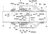
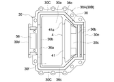
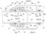
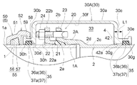
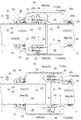
- Perspective view which shows 1st Embodiment of the detachment prevention structure of a pipe connection part Overall cross-sectional view at the time of assembly Overall sectional view at the time of withdrawal Overall cross-sectional view showing bending regulation operation in the detached state Split joint wheel case inner view Front view of the tilt control unit of the first embodiment Front view of a main part showing another connection structure of the tilt control part of the first embodiment Front view of the tilt control unit of the second embodiment Overall sectional view at the time of assembly showing the second embodiment of the disconnection prevention structure of the pipe connection portion.
- Overall vertical cross-sectional view at the time of withdrawal Overall sectional view at the time of assembly showing the third embodiment of the disconnection prevention structure of the pipe connection portion.
- Overall sectional view at the time of assembly showing the tenth embodiment of the disconnection prevention structure of the pipe connection portion.
- First Embodiment 1 to 4 show a disconnection prevention structure of a pipe connection portion used in a fluid transportation piping system.
- the insertion port 1A of the fluid pipe 1 which is an example of one pipe portion
- the receiving port 2A of the fluid pipe 2 which is an example of the other pipe portion
- the joint ring 30 having a split structure that surrounds the fitting connection portion 20 in a sealed state is exteriorized over both fluid pipes 1 and 2. As shown in FIGS.
- the socket 2A and the insertion port 1A are disconnected from each other at the portions of the joint ring 30 and the other fluid pipe 2 on the receiving port 2A side facing each other in the pipe axis direction.
- a first detachment blocking unit 4 is provided, which allows the relative detachment movement to the detached state and prevents the relative detachment movement of the receiving port 2A and the joint ring 30 in the detached state from contacting with each other.
- the insertion port 1A of the fluid pipe 1 is provided with a second detachment prevention portion 5 having a divided structure.
- the second detachment preventing portion 5 is a connecting portion 52 fixedly connected to the pipe support portion 30d on one end side in the pipe axis direction of the joint ring 30, and an insertion port 1A for the pipe support portion 30d on one end side of the joint ring 30.
- the retaining portion 55 is provided so that the retaining resistance with the outer peripheral surface 1a of the insertion port 1A increases with the detachment movement of the insertion port 1A.
- a tilt regulating portion 9 for restricting the tilt of the insertion port 1A with respect to the pipe support portion 30d on one end side of the joint ring 30 is provided in a detached state in which the receiving port 2A and the insertion port 1A are disconnected. Has been done.
- the fluid pipes 1 and 2 have been mentioned as an example of the pipe portion, but there have been various types of pipe portions conventionally.
- it constitutes a branch pipe portion of a split T-shaped pipe whose exterior is fixed to the fluid pipe in a sealed state, a branch pipe portion integrally protruding from the fluid pipe, and a part of fluid equipment.
- the pipe part and the like can be mentioned.
- the fluid pipes 1 and 2 of the present embodiment are ductile cast iron pipes constituting a water pipe for transporting clean water, which is an example of a fluid, but other cast iron pipes, steel pipes, and the like can be used.
- the fluid, industrial water, gas, etc. can be mentioned in addition to clean water.
- the fitting connection portion 20 between the insertion port 1A of one fluid pipe 1 and the receiving port 2A of the other fluid pipe 2 is composed of a K-shaped mechanical joint.
- a first seal member 21 such as a rubber ring is mounted between the outer peripheral surface 1a of the insertion port 1A and the tapered inner peripheral surface 2a of the receiving port 2A.
- a push ring 22 provided with a pressing portion 22a capable of pressing the first seal member 21 from the direction of the pipe axis is exteriorized at the insertion port 1A.
- the flange portion 22b of the push ring 22 and the flange portion 2b of the receiving port 2A are piped by a first fastener 25 such as a plurality of metal T-head bolts 23 and nuts 24 arranged at predetermined intervals in the pipe circumferential direction. It is tightened and connected from the axis direction. By tightening and connecting with the first fastener 25, the first seal member 21 is compressed into a sealed state (watertight state) by the pressing portion 22a of the push ring 22 which is attracted and fixed to the flange portion 2b of the receiving port 2A, and the sealed state is changed. Be maintained.
- a first fastener 25 such as a plurality of metal T-head bolts 23 and nuts 24 arranged at predetermined intervals in the pipe circumferential direction. It is tightened and connected from the axis direction.
- the joint ring 30 is made of cast iron having a two-divided structure that can be freely exteriorized over both fluid pipes 1 and 2 while surrounding the fitting connection portion 20 of both fluid pipes 1 and 2. It is composed of both split joint wheel cases 30A and 30B. As shown in FIGS. 2 and 5, the two split joint ring cases 30A and 30B are configured to have the same shape.
- the joint ring 30 has a cylindrical peripheral wall portion 30a having a diameter larger than that of the receiving port 2A, and an annular side wall portion integrally extending inward in the radial direction from both ends of the peripheral wall portion 30a in the pipe axis direction.
- the main configurations are 30b and 30c, and cylindrical pipe support portions 30d and 30e extending outward from the inner diameter side ends of the side wall portions 30b and 30c along the pipe axis direction.
- the side wall portion 30b on one end side on the insertion port 1A side is formed as a vertical side wall portion orthogonal to or substantially orthogonal to the tube axis.
- the side wall portion 30c on the other end side, which is on the receiving port 2A side, is configured as a tapered side wall portion having a smaller diameter toward the pipe support portion 30e side continuous with the side wall portion 30c.
- connecting flange portions 30C projecting outward in the horizontal direction are integrally formed at both ends of the joint ring 30 divided joint ring cases 30A and 30B in the pipe circumferential direction. ing.
- the connecting flange portions 30C of the two split joint wheel cases 30A and 30B are fixedly connected to each other in a sealed state (watertight state) by tightening the second fastener 34 such as the bolt 31 and the nut 32.
- the two split joint wheel cases 30A and 30B have the outer peripheral surfaces 1a of both fluid pipes 1 and 2 including the inner peripheral surface 30f (see FIG. 2) of the joint ring 30 and the fitting connection portion 20.
- a seal portion 35 (see FIG. 2) that seals the surrounding space 33 formed between the 2c and the outside with respect to the outside is provided.
- the seal portion 35 is provided with a second seal member 37 such as an annular gasket in the annular seal holding grooves 36 formed in each of the two split joint ring cases 30A and 30B. It is composed of.
- the seal holding groove 36 includes a first circumferential groove 36a formed on the inner surface of the pipe support portion 30d facing the semi-peripheral surface of the insertion port 1A and the receiving port 2A.
- Two second circumferential groove 36b and first and second circumferential groove 36a which are formed on the inner surface of the pipe support portion 30e facing the semi-peripheral surface at intervals in the pipe axis direction.
- a pipe axial groove portion 36c formed along a dividing surface of both connecting flange portions 30C in a state of communicating with the circumferential end portion of the 36b is provided.
- the second seal member 37 has a first circumferential seal portion 37a attached to the first circumferential groove 36a and a second seal member 37 attached to the second circumferential groove 36b of the two articles.
- the circumferential seal portion 37b and the tubular axial seal portion (not shown) mounted on the tubular axial groove portion 36c are integrally molded. Then, the pipe axial direction seal portions of both second seal members 37 come into contact with each other in a sealed state (watertight state) from the pipe radial direction between the divided surfaces of both connecting flange portions 30C.
- the first circumferential seal portion 37a and the second circumferential seal portion 37b of both second seal members 37 are formed on the outer peripheral surfaces 1a and 2c of both fluid pipes 1 and 2 at both pipe support portions 30d and 30e of the joint ring 30. Contact in a sealed state along the circumferential direction of the pipe.
- the first detachment preventing portion 4 is the inner peripheral surface 30f between the pipe support portions 30d and 30e of the split joint ring cases 30A and 30B, and is in the direction other than the pipe axis direction.
- a semi-circular ring projecting inward in the pipe radial direction from the pipe axis direction to a position where it can abut the head 23A of the plurality of T-head bolts 23 of the first fastener 25 at the portion displaced toward the end side.
- the detachment prevention wall portion 41 is integrally formed.
- the detachment prevention wall portion 41 is formed at the boundary portion between the peripheral wall portion 30a and the tapered side wall portion 30c on the inner peripheral surfaces 30f of the two split joint ring cases 30A and 30B.
- the side surfaces of the detachment prevention wall portion 41 are in a detached state due to the contact with the head 23A of the T-head bolt 23. It is configured on the contact surface 41a that prevents the relative detachment movement of the receiving port 2A and the joint ring 30 from contacting each other.
- a plurality of metal T-head bolts 23 arranged at predetermined intervals in the circumferential direction of the pipe are also configured as a contact member 45 fixed to the receiving port 2A side, and the head 23A of each T-head bolt 23 is configured.
- the contact surface 23a which is a flat top surface, is formed on the contact surface 45a of the contact member 45.
- Each of the contact surface 41a of the detachment prevention wall portion 41 and the contact surface 45a of the contact member 45 composed of the contact surface 23a of the head portion 23A of each T-head bolt 23 is orthogonal to the pipe axis. It is formed on the orthogonal planes.
- the contact member 45 is composed of the contact surface 41a of the detachment prevention wall portion 41 in the joint ring 30 and the contact surface 23a of the head 23A of each T head bolt 23 fixed to the receiving port 2A side.
- the contact surface 45a comes into contact with the pipe axis from the direction of the pipe axis, and the further detachment movement between the receiving port 2A of the fluid pipe 2 and the joint ring 30 is prevented.
- the detachment prevention wall portion 41 in the joint ring 30 and the contact surface 45a of the contact member 45 are formed on orthogonal surfaces orthogonal to the pipe axis, the detachment prevention wall The contact surface 41a of the portion 41 and the contact surface 45a of the contact member 45 are in a surface contact state along the orthogonal direction. As a result, the withdrawal force can be reliably received and the withdrawal prevention effect can be improved. Further, since the push-opening force of the split joints acting on the split joints 30A and 30B of the joint rings 30 is not generated at the time of contact, the sealing performance of the split joints 30A and 30B is reduced. It can be suppressed.
- the initial assembly state is a state in which the tip of the T-head bolt 23 of the fitting connection portion 20 is in contact with the inner surface of the side wall portion 30b on one end side of the joint ring 30.
- the state in which the contact surface 23a of the head 23A of the T-head bolt 23 is in contact with the contact surface 41a of the detachment prevention wall portion 41 in the joint ring 30 is the maximum detachment movement state.
- the maximum detachment movement state Become.
- the distance from the contact surface 23a of the head 23A of the T-head bolt 23 to the contact surface 41a of the detachment prevention wall portion 41 in the initial assembly state becomes the maximum detachment movement distance L.
- the connection between the insertion port 1A of one fluid tube 1 and the socket 2A of the other fluid tube 2 is released.
- the second detachment prevention portion 5 is composed of a seismic retrofitting metal fitting 50 having a divided structure.
- the seismic retrofitting metal fitting 50 is divided into two in the pipe circumferential direction, and a pair of metal split holding members 51 that are detachably held and fixed to the insertion port 1A of one of the fluid pipes 1 from the pipe radial direction. Is provided.
- the pair of split holding members 51 inserts the fluid pipe 1 by tightening and connecting the flange portions 51A provided at both ends in the pipe circumferential direction with a third fastener 47 such as a bolt 48 and a nut 49. It is firmly sandwiched and fixed to the mouth 1A.
- the connecting portion 52 of the seismic retrofitting metal fitting 50 has an annular engaging protrusion 53 protruding from the outer peripheral surface of the pipe supporting portion 30d on one end side of the joint ring 30, and a pipe radial direction outside the engaging protrusion 53. It includes an engaging recess 54 that can be engaged and disengaged from the side. Among them, the engaging recess 54 is formed as an opening inward in the pipe radial direction at a portion of each of the divided sandwiching members 51 that integrally projects from the middle portion in the pipe circumferential direction along the pipe axis direction.
- the engaging recess 54 integrally formed in the two split holding members 51 is formed at one end of the joint ring 30.
- the engagement protrusion 53 of the pipe support portion 30d on the side is engaged from the outer side in the pipe radial direction, and in this state, the flange portions 51A of the two split holding members 51 are engaged with each other with the bolt 48 and the nut 49 of the third fastener 47. Tighten and connect with.
- gap regulation bolts 58 that come into contact with the outer peripheral surface 1a of the insertion port 1A from the pipe radial direction are screwed into a plurality of pipe support portions 30d on one end side of the joint ring 30 in the pipe circumferential direction. There is. By the screwing operation of the plurality of gap regulating bolts 58, the annular gap between the inner peripheral surface of the pipe support portion 30d on one end side and the outer peripheral surface 1a of the insertion port 1A is constantly regulated.
- the retaining portion 55 of the seismic retrofitting metal fitting 50 includes a claw storage portion 56 formed on the inner peripheral surface of the two-split holding member 51 and opening inward in the radial direction, and the claw.
- a claw member 57 that is movably accommodated inward in the pipe radial direction is provided in the accommodating portion 56.
- On the inner surface of the claw member 57 a plurality of rows of sharp tapered blades along the circumferential direction of the pipe that can bite into the outer peripheral surface 1a of the insertion port 1A are formed.
- the outer surface of the claw member 57 and the ceiling surface of the claw storage portion 56 are housed in the claw storage portion 56 in a state of biting into the claw storage portion 56 of the double-split holding member 51 and the outer peripheral surface 1a of the insertion port 1A. It is formed on an inclined surface that bites and moves the claw member 57 inward in the radial direction with the relative detachment movement in the direction of the tube axis.
- the connecting portion 52 of the seismic retrofitting metal fitting 50 having a split structure provided in the insertion port 1A is fixedly connected to the pipe support portion 30d on one end side of the joint ring 30. The connection between the joint ring 30 and the seismic retrofitting metal fitting 50 is firmly maintained.
- the claw member 57 of the retaining portion 55 of the seismic retrofitting metal fitting 50 is pulled out by biting into the outer peripheral surface 1a of the insertion port 1A as the insertion port 1A detaches from the pipe support portion 30d on one end side of the joint ring 30. Stop resistance increases. Therefore, as a whole, the insertion port 1A of one of the fluid pipes 1 and the pipe support portion 30d on one end side of the joint ring 30 are integrally and firmly fixedly connected via the seismic retrofitting metal fitting 50. As a result, as shown in FIG.
- the receiving port 2A moves out of the pipe support portion 30e on the other end side of the joint ring 30 and the joint ring 30 It is possible to firmly prevent the insertion port 1A from moving out of the pipe support portion 30d on one end side.
- the pipe support portion 30d on one end side of the joint ring 30 and the retaining portion 55 of the seismic retrofitting metal fitting 50 support two locations at the insertion port 1A of the fluid pipe 1 at intervals in the pipe axis direction. As shown in 3, when the insertion port 1A and the receiving port 2A are disconnected from each other, the bending of the insertion port 1A and the pipe support portion 30d on one end side of the joint ring 30 can be suppressed.
- the tilt regulating unit 9 is inserted in a state in which the insertion port 1A of one fluid pipe 1 and the receiving port 2A of the other fluid pipe 2 are fitted and connected to each other and in a detached state.
- a tilt restricting body 90 externally attached to 1A and a fixed connecting portion 91 for fixing and connecting the tilt regulating body 90 to the receiving port 2A are provided.
- the tilt restricting body 90 is integrally formed with a tilt regulating cylinder 90b having an inner diameter slightly larger than the outer diameter of the insertion port 1A, and a tilt regulating cylinder 90b radially outward from the outer peripheral surface of the tilt regulating cylinder 90b. It has a connecting flange portion 90c that projects in a symmetrical manner.
- the tilt regulating surface 90a of the tilt restricting body 90 has an insertion port 1A with respect to the pipe support portion 30d on one end side of the joint ring 30 in a detached state in which the insertion port 1A and the receiving port 2A are disconnected. At the time of tilting, it contacts the outer surface of the end portion of the insertion port 1A to regulate further tilting.
- the tilt restricting body 90 is divided into two in the circumferential direction of the pipe, and is detachably attached to the insertion port 1A from the radial direction of the pipe. It is composed of regulating members 90A and 90B.
- the pair of split tilt regulating members 90A and 90B are inserted by tightening and connecting the connecting pieces 90d provided at both ends in the pipe circumferential direction with a fourth fastener 92 such as a bolt 93 and a nut 94. It is formed in an annular shape along the outer peripheral surface 1a of 1A.
- the connecting flange portions 90c of the split tilt regulating members 90A and 90B are on one end side of the joint ring 30 in a detached state in which the insertion port 1A and the receiving port 2A are disconnected.
- a tilt regulating protrusion 95 is provided to regulate further tilting of the insertion port 1A by abutting against the inner surface of the joint ring 30 as the insertion port 1A tilts with respect to the pipe support portion 30d.
- the tilt restricting protrusion 95 is provided at one or a plurality of connecting flange portions 90c.
- the tilt regulating protrusion 95 is formed so as to protrude outward in the pipe radial direction from two locations in the circumferential direction of each connecting flange portion 90c.
- the tilt regulating tube 90b of the split tilt regulating members 90A and 90B has a taper formed between the tapered inner peripheral surface 22c of the push ring 22 and the outer peripheral surface 1a of the insertion port 1A.
- An engaging protrusion 90e that engages with the shape gap from the direction of the tube axis is projected.
- the engaging protrusions 90e of the two split tilt regulating members 90A and 90B have a tapered inner peripheral surface 22c of the push ring 22 even when the insertion port 1A and the receiving port 2A are disconnected from each other. Engagement with is maintained.
- the fixed connecting portion 91 of the tilt regulating portion 9 is composed of the first fastener 25 of the fitting connecting portion 20. Specifically, a bolt insertion hole through which the tip of the T-head bolt 23 can be inserted into a portion of the connecting flange portion 90c of the two split tilt regulating members 90A and 90B corresponding to each T-head bolt 23 of the first fastener 25. Form 91a.
- a fixed connecting nut 91b is screwed into the tip of the T-head bolt 23 into which the bolt insertion holes 91a of the split tilt regulating members 90A and 90B are inserted. By tightening the fixed connecting nut 91b, the tilt restricting body 90 is fixedly connected to the receiving port 2A.
- the insertion port 1A may tilt with respect to the pipe support portion 30d on one end side of the joint ring 30.
- the outer surface of the end portion of the insertion port 1A abuts on the tilt control surface 90a of the tilt control body 90, and a part of the tilt control protrusion 95 of the tilt control body 90 abuts on the inner surface of the joint ring 30.
- the bent state of the insertion port 1A and the pipe support portion 30d on one end side of the joint ring 30 in the detached state is maintained within an appropriate range, and the sealing performance of the sealing portion 35 in the circumferential direction is reduced.
- the resulting fluid leakage can be suppressed.
- the configuration is not limited to this.
- the first detachment prevention portion 4 will be described with reference to FIGS. 2 and 3, both pipe support portions 30d and 30e of the joint ring 30.
- a thick-walled detachment prevention portion 42 that can be contacted is formed on the other end side of the inner surface between the pipe shafts in the direction of the pipe shaft core, in other words, on the side wall portion 30c on the other end side of the joint ring 30, from the tapered outer peripheral surface portion 2e on the outer peripheral surface 2c of the receiving port 2A and the pipe shaft core direction.
- a thick-walled detachment prevention portion 42 that can be contacted is formed.
- the contact surface 42a of the detachment prevention portion 42 is formed in a tapered shape having the same slope as the tapered outer peripheral surface portion 2e on the outer peripheral surface 2c of the receiving port 2A.
- the first detachment prevention portion 4 when a detachment force due to an earthquake, uneven settlement, or the like acts on the fitting connection portion 20 between the insertion port 1A and the receiving port 2A, the side wall on the other end side of the joint ring 30.
- the contact surface 42a of the detachment blocking portion 42 formed in the portion 30c and the tapered outer peripheral surface portion 2e on the outer peripheral surface 2c of the receiving port 2A can come into contact with each other to prevent further detachment movement of both.
- the contact surface 42a of the detachment prevention portion 42 is formed in a tapered shape having the same slope as the tapered outer peripheral surface portion 2e on the outer peripheral surface 2c of the receiving port 2A, the contact surface 42a of the detachment prevention portion 42a. And the tapered outer peripheral surface portion 2e of the receiving port 2A come into contact with each other in a surface contact state, and the detachment movement of the receiving port 2A and the joint ring 30 can be strongly prevented. Moreover, when the contact surface 42a of the detachment blocking portion 42 abuts on the tapered outer peripheral surface portion 2e of the receiving port 2A, a force is generated to push open the divided surface of the joint ring 30 of the divided structure.
- the contact surface 42a of the detachment preventing portion 42 is formed on the other end side of the joint ring 30 between the two pipe support portions 30d and 30e in the pipe axis direction, so that both pipe support portions 30d.
- the push-opening force becomes smaller by the deviation allowance at which the contact surface 42a of the detachment blocking portion 42 deviates from 30e, and fluid leakage occurs due to a decrease in the sealing property of the seal portion 35 due to the push-opening of the split surface of the joint ring 30. Can be suppressed.
- connection structure of the tilt control body 90 of the first embodiment As shown in FIG. 6, as a first embodiment of the tilt regulating body 90, the connecting pieces 90d provided at both ends of the split tilt regulating members 90A and 90B in the pipe circumferential direction are bolted to each other. It was connected by a fourth fastener 92 such as 93 and a nut 94.
- a fourth fastener 92 such as 93 and a nut 94.
- FIG. 7 may be adopted.
- a second connecting piece 90f that can be polymerized and arranged from the pipe radial direction is integrally formed at each of both ends of the split tilt regulating members 90A and 90B in the pipe circumferential direction.
- a second bolt insertion hole 91c through which the tip of the T-head bolt 23 can be inserted is formed in the second connecting piece 90f of each set to be polymerized.
- the tilt regulating protrusion 95 is configured so that the contact position with respect to the inner surface of the joint ring 30 can be changed in the pipe radial direction.
- the tilt regulating protrusion 95 is screwed into the female screw portion 95A formed at two locations in the circumferential direction of each of the split tilt regulating members 90A and 90B, and the female screw portion 95A from the pipe radial direction. It includes a tilt control bolt 95B and a lock nut 95C for fixing the tilt control bolt 95B whose contact position in the pipe radial direction is adjusted. By screwing the tilt control bolt 95B, the contact position of the joint ring 30 with respect to the inner surface is changed in the pipe radial direction.
- the tilt restricting body 90 having the split structure of the tilt regulating portion 9 is exteriorized to the insertion port 1A, there is a site where the receiving port 2A and the insertion port 1A are bent at the fitting connection portion 20.
- the contact position of the tilt control bolt 95B is set to the pipe diameter according to the measured distance between the tip of the tilt control bolt 95B of the tilt control body 90 and the protrusion contact portion on the inner peripheral surface 30f of the joint ring 30. Can be changed in direction.
- the exterior assembly work of the tilt regulating unit 9 with respect to the insertion port 1A can be efficiently and reliably performed. ..
- the tilt regulating bolt 95B of the tilt regulating body 90 can be accurately brought into contact with the inner surface of the joint ring 30. ..
- the bent state of the insertion port 1A and the pipe support portion 30d on one end side of the joint ring 30 in the detached state is maintained within an appropriate range, which is caused by the local deterioration of the sealing performance of the sealing portion 35 in the circumferential direction. It is possible to suppress the leakage of the fluid. Since the other configurations are the same as the configurations described in the first embodiment, the same numbers as those in the first embodiment are added to the same configuration parts, and the description thereof will be omitted.
- the fitting connection portion 20 between the insertion port 1A of one fluid pipe 1 and the receiving port 2A of the other fluid pipe 2 is T-shaped. It is composed of mechanical joints of. In this T-shaped mechanical joint, the outer peripheral surface 1a of the insertion port 1A is fitted and connected to the receiving port 2A in the annular seal holding groove 60 formed on the inner peripheral surface of the receiving port 2A and opening inward in the radial direction.
- a third seal member 61 such as a rubber ring that is compressed into a sealed state (watertight state) is attached to the surface.
- a tilt regulating unit 9 for regulating the tilt of the insertion port 1A is provided. As shown in FIGS. 11 and 12, the tilt regulating unit 9 is inserted in a state in which the insertion port 1A of one fluid tube 1 and the receiving port 2A of the other fluid tube 2 are fitted and connected and in a detached state.
- a tilt restricting body 90 externally attached to 1A and a fixed connecting portion 91 for fixing and connecting the tilt regulating body 90 to the receiving port 2A are provided.
- the tilt control body 90 has a tilt control surface 90a having an inner diameter slightly larger than the outer diameter of the insertion port 1A. As shown in FIG. 12, the tilt regulating surface 90a is in a detached state in which the insertion port 1A and the receiving port 2A are disconnected, and when the insertion port 1A is tilted with respect to the pipe support portion 30d on one end side of the joint ring 30. It abuts on the outer surface of the end of the insertion slot 1A to regulate further tilting.
- the tilt restricting body 90 is divided into two in the circumferential direction of the pipe, and is detachably attached to the insertion port 1A from the radial direction of the pipe.
- the split tilt regulating members 90C and 90D are provided.
- the pair of second split tilt regulating members 90C and 90D are connected by tightening 90 g of the third connecting pieces provided at both ends in the pipe circumferential direction with a fourth fastener 92 such as a T-head bolt 93A and a nut 94. By doing so, it is formed in an annular shape along the outer peripheral surface 1a of the insertion port 1A.
- both the second split tilt regulating members 90C and 90D have a pipe support portion on one end side of the joint ring 30 in a detached state in which the insertion port 1A and the receiving port 2A are disconnected.
- a tilt regulating protrusion 95 is provided to regulate the further tilt of the insertion port 1A by abutting against the inner surface of the joint ring 30 as the insertion port 1A tilts with respect to 30d.
- the tilt regulating protrusions 95 are provided at one or more locations of the divided tilt regulating members 90A and 90B.
- the tilt regulating protrusion 95 is formed so as to protrude outward from two locations in the circumferential direction of the divided tilt regulating members 90A and 90B along the pipe radial direction.
- the tilt control protrusion 95 is configured so that the contact position of the joint ring 30 with respect to the inner surface can be changed in the pipe radial direction.
- the tilt regulating protrusion 95 is screwed into the female screw portion 95A formed at two locations in the circumferential direction of each of the split tilt regulating members 90A and 90B, and the female screw portion 95A from the pipe radial direction. It includes a tilt control bolt 95B and a lock nut 95C for fixing the tilt control bolt 95B whose contact position in the pipe radial direction is adjusted. By screwing the tilt control bolt 95B, the contact position of the joint ring 30 with respect to the inner surface is changed in the pipe radial direction.
- the fixed connecting portion 91 is provided on the tilt restricting body 90 in a state where it can be engaged and disengaged from the outside in the pipe radial direction with respect to the annular protrusion 2g formed at the end of the outer peripheral surface 2c of the receiving port 2A.
- the third connecting pieces 90g of the second split tilt regulating members 90C and 90D are inserted into the insertion port 1A. It is composed of a fourth fastener 92 that is tightened and fixed in a holding state.
- the socket 2A and the insertion port 1A are disconnected from each other at the portions of the joint ring 30 and the other fluid pipe 2 on the receiving port 2A side in the direction of the tube axis.
- a first detachment blocking unit 4 is provided, which allows the relative detachment movement to the detached state and prevents the relative detachment movement of the receiving port 2A and the joint ring 30 in the detached state from contacting with each other.
- the first detachment prevention portion 4 is the inner peripheral surface 30f between the pipe support portions 30d and 30e of the two split joint ring cases 30A and 30B, and is in the direction other than the pipe axis direction.
- a protruding semicircular ring-shaped detachment prevention wall portion 41 is integrally formed.
- the detachment prevention wall portion 41 is formed at the boundary portion between the peripheral wall portion 30a and the tapered side wall portion 30c on the inner peripheral surfaces 30f of the two split joint ring cases 30A and 30B.
- the side surfaces facing the contact portions 90h of the two second division tilt regulating members 90C and 90D in the direction of the pipe axis are the hit surfaces of the two second division tilt regulating members 90C and 90D. It is configured as a contact surface 41a that prevents the relative detachment movement of the receiving port 2A and the joint ring 30 in the detached state by abutting with the contact portion 90h. Since the other configurations are the same as the configurations described in the first embodiment, the same numbers as those in the first embodiment are added to the same configuration parts, and the description thereof will be omitted.
- [Fourth Embodiment] 14 and 15 show a disconnection prevention structure of a pipe connection portion used in a fluid transportation piping system.
- the insertion port 1A of the fluid pipe 1 which is an example of one pipe portion and the receiving port 2A of the fluid pipe 2 which is an example of the other pipe portion are connected by the fitting connection portion 20.
- the joint ring 30 having a split structure that surrounds the fitting connection portion 20 in a sealed state is exteriorized over both fluid pipes 1 and 2.
- the fitting connection portion 20 is composed of a K-shaped mechanical joint as in the first embodiment. As shown in FIGS.
- the socket 2A and the insertion port 1A are disconnected from each other at the portions of the joint ring 30 and the other fluid pipe 2 on the receiving port 2A side in the direction of the tube axis.
- a first detachment blocking unit 4 is provided, which allows the relative detachment movement to the detached state and prevents the relative detachment movement of the receiving port 2A and the joint ring 30 in the detached state from contacting with each other.
- the insertion port 1A of the fluid pipe 1 is provided with a second detachment prevention portion 5 having a divided structure.
- the second detachment preventing portion 5 is a connecting portion 52 fixedly connected to the pipe support portion 30d on one end side in the pipe axis direction of the joint ring 30, and an insertion port 1A for the pipe support portion 30d on one end side of the joint ring 30.
- the retaining portion 55 is provided so that the retaining resistance with the outer peripheral surface 1a of the insertion port 1A increases with the detachment movement of the insertion port 1A.
- the joint ring 30 is made of cast iron having a two-divided structure that can be freely exteriorized over both fluid pipes 1 and 2 while surrounding the fitting connection portion 20 of both fluid pipes 1 and 2. It is composed of both split joint wheel cases 30A and 30B.
- the joint ring 30 has a cylindrical peripheral wall portion 30a having a diameter larger than that of the receiving port 2A, and an annular side wall portion 30b extending radially inward from both ends of the peripheral wall portion 30a in the pipe axis direction.
- 30c and cylindrical pipe support portions 30d, 30e extending integrally outward from the inner diameter side ends of the side wall portions 30b, 30c along the pipe axis direction are provided as the main configurations. There is.
- connections are made to both ends of the joint ring 30 divided joint ring cases 30A and 30B in the pipe circumferential direction so as to be fixedly connected to each other via a second fastener 34 such as a bolt 31 and a nut 32.
- the flange portion 30C is integrally formed.
- the divided surfaces of the two divided joint ring cases 30A and 30B are between the inner peripheral surface 30f of the joint ring 30 (see FIG. 16) and the outer peripheral surfaces 1a and 2c of both fluid pipes 1 and 2 including the fitting connection portion 20.
- a seal portion 35 (see FIG. 15) is provided to seal the surrounding space 33 formed in the water tightly to the outside. As shown in FIGS.
- the seal portion 35 has a second seal member 37 such as an annular gasket in the annular seal holding groove 36 formed on each of the divided surfaces of the two divided joint ring cases 30A and 30B. It is configured by wearing.
- the second seal members 37 are in watertight contact with each other from the pipe radial direction at both ends of the split joint ring cases 30A and 30B in the pipe circumferential direction, and both are in the pipe support portions 30d and 30e of the joint ring 30. It contacts the outer peripheral surfaces 1a and 2c of the fluid pipes 1 and 2 in a watertight state along the pipe circumferential direction.
- the first detachment preventing portion 4 is on the inner peripheral surface side of the pipe support portion 30e on the other end side of the joint ring 30 in the pipe axis direction and in the pipe support portion 30e.
- the second circumferential groove portion 36b of the seal holding groove 36 formed on the inner peripheral surface and the second circumferential seal portion 37b of the second seal member 37 attached thereto are biased toward the center side in the pipe axis direction of the joint ring 30.
- a detachment prevention portion 42 having an outer peripheral surface 2c of the receiving port 2A and an annular contact surface 42a capable of contacting from the pipe axis direction is formed at the positioned portion.
- the detachment prevention portion 42 is formed to have a diameter smaller than the inner diameter of the partition wall 30g located on both sides of the second circumferential groove portion 36b in the pipe axis direction on the inner peripheral surface of the pipe support portion 30e on the other end side.
- the inner peripheral surface of the detachment blocking portion 42 is formed so as to protrude inward in the radial direction from the inner peripheral surface of the partition wall 30 g located on both sides of the second circumferential groove portion 36b.
- the detachment prevention portion 42 is integrally formed with one partition wall 30g, and has a reinforcing structure in which the thickness in the pipe axis direction from the contact surface 42a of the detachment prevention portion 42 to the second circumferential groove portion 36b of the seal holding groove 36 is also large. It is configured in. Further, the contact surface 42a of the detachment prevention portion 42 is formed at the same or substantially the same inclination angle as the inclination angle of the tapered contact portion 2d of the outer peripheral surface 2c of the receiving port 2A.
- the tip of the T-head bolt 23 of the fitting connection portion 20 is in contact with the inner surface of the side wall portion 30b on one end side of the joint ring 30. It will be in the initial assembly state. Further, as shown in FIG. 17, the contact surface 42a of the detachment blocking portion 42 formed on the pipe support portion 30e on the other end side of the joint ring 30 corresponds to the tapered contact portion 2d of the outer peripheral surface 2c of the receiving port 2A. The state of contact is the maximum detachment movement state. As a result, as shown in FIG.
- the tip of the T-head bolt 23 is in the maximum detached movement state from the tip position of the T-head bolt 23 or the inner surface of the side wall portion 30b on one end side of the joint ring 30 in the initial assembly state.
- the distance to the position is the maximum detachment movement distance L, and in the maximum detachment movement state, the connection between the insertion port 1A of one fluid pipe 1 and the receiving port 2A of the other fluid pipe 2 is released.
- a detaching force due to an earthquake, uneven settlement, or the like acts on the fitting connection portion 20 between the insertion port 1A and the receiving port 2A, and the pipe support portion 30e on the other end side of the joint ring 30 acts.
- the contact surface 42a of the detachment blocking portion 42 formed on the inner peripheral surface side abuts on the tapered contact portion 2d of the outer peripheral surface 2c of the receiving port 2A, a force that pushes open the divided surface of the joint ring 30 of the divided structure. Occurs.
- the detachment prevention portion 42 of the joint ring 30 is formed at a portion deviated from the second circumferential groove portion 36b of the seal holding groove 36 toward the center side in the tube axis direction of the joint ring 30.
- the pushing-opening force is reduced by the amount of the deviation allowance, and it is possible to suppress the occurrence of fluid leakage due to a decrease in the sealing property (decrease in surface pressure) of the seal portion 35 due to the push-opening of the divided surface of the joint ring 30.
- the distance L1 to 36b is the joint ring 30 of the partition walls 30h on both sides in the pipe axis direction in the first circumferential groove 36a of the seal holding groove 36 formed on the inner peripheral surface of the pipe support portion 30d on one end side. It is configured to be larger than the thickness dimension in the pipe axis direction on the inner side partition wall 30h on the center side in the pipe axis direction.
- the thickness dimension corresponding to the distance L1 from the contact surface 42a of the detachment prevention portion 42 of the joint ring 30 to the groove portion 36b in the second circumferential direction of the seal portion 35 is the pipe on one end side of the joint ring 30. Since the support portion 30d is configured to be larger than the thickness dimension of the partition wall 30h of the first circumferential groove portion 36a in the pipe axis direction, the detachment prevention portion 42 that abuts on the outer peripheral surface 2c of the receiving port 2A is made sturdy. Can be configured.
- the second detachment prevention portion 5 is composed of the seismic retrofitting metal fitting 50 having a divided structure.
- the connecting portion 52 of the seismic retrofitting metal fitting 50 has an annular engaging recess 58 formed on the outer peripheral surface of the pipe supporting portion 30d on one end side and opening outward in the radial direction, and a pipe radial direction with respect to the engaging recess 58. It is composed of an engaging protrusion 59 that is engageable and disengaged from the outside.
- the engaging protrusions 59 are integrally formed so as to protrude from a plurality of locations in the pipe circumferential direction of the bipartite holding member 51 along the pipe axis direction.
- the engaging protrusion 59 integrally formed with the two split holding members 51 is supported by the pipe on one end side.
- the flange portions 51A of the two split sandwiching members 51 are fastened and connected with a third fastener 47 such as a bolt 48 and a nut 49.
- the retaining portion 55 of the seismic retrofitting metal fitting 50 has the same structure as the retaining portion 55 described in the first embodiment. Therefore, the same number as that of the first embodiment is added to the same configuration portion, and the description thereof will be omitted.
- the fitting connection portion 20 between the insertion port 1A of one fluid pipe 1 and the receiving port 2A of the other fluid pipe 2 has the same T-shape as in the third embodiment. It consists of a mechanical joint. Since the other configurations are the same as the configurations described in the fourth embodiment, the same numbers as those in the fourth embodiment are added to the same configuration parts, and the description thereof will be omitted.
- the fitting connection portion 20 between the insertion port 1A of one fluid pipe 1 and the receiving port 2A of the other fluid pipe 2 is composed of a T-shaped mechanical joint.
- an improvement of the first detachment prevention portion 4 for preventing the relative detachment movement of the other fluid pipe 2 from the receiving port 2A and the joint ring 30 by contact with each other is shown.
- the outer peripheral surface 2c of the socket 2A is located at a portion displaced toward the center of the joint ring 30 in the pipe axis direction from the second circumferential groove portion 36b and the second circumferential seal portion 37b of the second seal member 37 attached thereto.
- a detachment prevention portion 42 having an annular contact surface 42a capable of contacting from the tapered contact portion 2d and the pipe axis direction is formed.
- the detachment prevention portion 42 On the inner peripheral surface of the pipe support portion 30e on the other end side of the joint ring 30, and at a portion deviated from the detachment prevention portion 42 toward the center of the joint ring 30 in the pipe axis direction, the detachment prevention portion 42 is applied.
- An annular elastic sealing material 43 is provided to seal between the contact surface 42a and the outer peripheral surface 2c of the receiving port 2A in a state where the contact surface 42a is in contact with the tapered contact portion 2d of the outer peripheral surface 2c of the receiving port 2A.
- the second seal holding groove 44 for holding the contact surface 42a of the detachment preventing portion 42 and the elastic sealing material 43 is formed on the inner peripheral surface of the side wall portion 30c on the other end side of the joint ring 30, and the side wall portion on the other end side.
- the thickness of the 30c in the tube axis direction is larger than the thickness of the side wall portion 30b on one end side of the joint ring 30 in the tube axis direction (see FIGS. 15 in the fourth embodiment and FIG. 18 in the fifth embodiment). Has been done.
- the elastic sealing material 43 provided at the portion deviated from the contact surface 42a of the detachment preventing portion 42 toward the center side in the tube axis direction of the joint ring 30 seals between the receiving port 2A and the outer peripheral surface 2c. Therefore, the fluid does not flow into the damaged portion of the covering protective layer, and the progress of corrosion of the socket 2A at the damaged portion of the covering protective layer can be suppressed. Since the other configurations are the same as the configurations described in the fifth embodiment, the same numbers as those in the fifth embodiment are added to the same configuration parts, and the description thereof will be omitted.
- the fitting connection portion 20 between the insertion port 1A of one fluid pipe 1 and the receiving port 2A of the other fluid pipe 2 is composed of a K-shaped mechanical joint. ..
- an improvement of the first detachment prevention portion 4 for preventing the relative detachment movement of the other fluid pipe 2 from the receiving port 2A and the joint ring 30 by contact with each other is shown.
- the first detachment prevention portion 4 of this embodiment is a plurality of metal T-heads arranged at predetermined intervals in the circumferential direction of the pipe among the constituent members of the K-shaped mechanical joint constituting the fitting connection portion 20.
- the bolt 23 is also configured as a contact member 45 fixed to the receiving port 2A side.
- the contact surface 23a which is the flat top surface of the head portion 23A of each T-head bolt 23, is formed on the contact surface 45a of the contact member 45.
- the inner surface portion facing the head portion 23A of each T head bolt 23 in the pipe axis direction is configured as the contact surface 46.
- Each of the contact surface 46 formed on the inner surface of the side wall portion 30c and the contact surface 23a of the head portion 23A of each T-head bolt 23 is formed as an orthogonal surface orthogonal to the pipe axis.
- the detachment force can be reliably received and the detachment prevention effect can be improved. Since the other configurations are the same as the configurations described in the fourth embodiment, the same numbers as those in the fourth embodiment are added to the same configuration parts, and the description thereof will be omitted.
- the flat contact surface 23a of the head 23A of each T-head bolt 23 is also configured as the contact surface 45a of the contact member 45, as shown in FIG. 21A.
- a contact member 45 having a contact surface 46 of the side wall portion 30c of the joint ring 30 and a contact surface 45a capable of contacting from the pipe axis direction is integrally formed on the head portion 23A of each T-head bolt 23. May be carried out.
- the contact surface 46 of the joint ring 30 and the contact surface 45a of the contact member 45 on each T-head bolt 23 on the receiving port 2A side are formed on orthogonal surfaces orthogonal to the pipe axis. ..
- the contact surface 46 of the joint ring 30 and the contact surface 45a of the contact member 45 in each T-head bolt 23 come into contact with each other, and the detachment force can be reliably received to improve the detachment prevention effect.
- the head portion 23A of each T-head bolt 23 is provided with a contact surface 46 of the side wall portion 30c of the joint ring 30 and a contact surface 45a capable of contacting from the pipe axis direction.
- the abutting member 45 provided may be fitted and fixed as an attachment.
- the contact surface 46 of the joint ring 30 and the contact surface 45a of the contact member 45B of each T-head bolt 23 on the receiving port 2A side are formed on orthogonal surfaces orthogonal to the pipe axis. ..
- the contact surface 46 of the joint ring 30 and the contact surface 45a of the contact member 45B of each T-head bolt 23 come into contact with each other, and the detachment force can be reliably received to improve the detachment prevention effect.
- the fitting connection portion 20 between the insertion port 1A of one fluid pipe 1 and the receiving port 2A of the other fluid pipe 2 is composed of a T-shaped mechanical joint. ..
- an improvement of the first detachment prevention portion 4 for preventing the relative detachment movement of the other fluid pipe 2 from the receiving port 2A and the joint ring 30 by contact with each other is shown.
- the first detachment prevention unit 4 of this embodiment is an example of the contact member 45 fixed to the receiving port 2A side of the other fluid pipe 2 from the outside in the pipe radial direction with respect to the receiving port 2A of the fluid pipe 2.
- a metal contact band 70 having a split structure (two split structure in the embodiment) that is held and fixed is used.
- the contact band 70 is provided with an annular first positioning portion 70b that abuts on the end surface of the receiving port 2A on the connection port side and a second positioning portion 70c that abuts on the tapered portion of the outer peripheral surface 2c of the receiving port 2A. Has been done. Therefore, in a state where the contact band 70 is tightened and fixed to the outer peripheral surface of the receiving port 2A, the first positioning portion 70b and the second positioning portion 70c prevent the contact band 70 from moving in the tube axis direction. ..
- the tip surface 70a of the second positioning portion 70c of the contact band 70 is formed on the contact surface 45a of the contact member 45.
- the inner surface portion facing the tip surface 70a of the second positioning portion 45c of the contact band 70 in the pipe axis direction abuts. It is configured on the surface 46.
- the contact surface 46 of the joint ring 30 and the tip surface 70a of the contact band 70 fixed to the receiving port 2A are formed on orthogonal surfaces orthogonal to the pipe axis.
- the contact surface 46 of the joint ring 30 and the contact surface 45a of the contact band 70 come into contact with each other, and the detachment force can be reliably received to improve the detachment prevention effect. Since the other configurations are the same as the configurations described in the fourth embodiment, the same numbers as those in the fourth embodiment are added to the same configuration parts, and the description thereof will be omitted.
- the fitting connection portion 20 between the insertion port 1A of one fluid pipe 1 and the receiving port 2A of the other fluid pipe 2 is composed of a K-shaped mechanical joint. ..
- an improvement of the first detachment prevention portion 4 for abutting and preventing the relative detachment movement of the other fluid pipe 2 between the receiving port 2A and the joint ring 30 above a certain level is shown.
- the first detachment prevention portion 4 of this embodiment is an example of the contact member 45 fixed to the receiving port 2A side of the other fluid pipe 2, and is an example of the contact member 45, which is from the outside in the pipe radial direction with respect to the flange portion 2b of the receiving port 2A.
- a metal receiving band 71 that is held and fixed in an engaged state is used.
- the tip surface 71a of the receiving band 71 is formed on the contact surface 45a of the contact member 45.
- the inner surface portion facing the tip surface 71a of the receiving band 71 in the tube axis direction is configured as the contact surface 46. There is.
- each of the contact surface 46 of the joint ring 30 and the tip surface 71a of the socket band 71 fixed to the socket 2A are formed as orthogonal planes orthogonal to the pipe axis.
- the contact surface 46 of the joint ring 30 and the contact surface 45a of the receiving band 71 come into contact with each other, and the detaching force can be reliably received to improve the detachment preventing effect. Since the other configurations are the same as the configurations described in the fourth embodiment, the same numbers as those in the fourth embodiment are added to the same configuration parts, and the description thereof will be omitted.
- the fitting connection portion 20 between the insertion port 1A of one fluid pipe 1 and the receiving port 2A of the other fluid pipe 2 is composed of a K-shaped mechanical joint. ..
- a seismic retrofitting metal fitting having a split structure in which the insertion port 1A of one fluid pipe 1 and the pipe support portion 30d on one end side of the joint ring 30 in the pipe axis direction are integrally fixedly connected. Shows 50 improvements.
- the first circumferential direction groove portion 36a of the seal holding groove 36 formed on the inner peripheral surface thereof and the groove portion 36a in the first circumferential direction.
- An extension pipe support portion 30j having an annular space that opens inward in the radial direction is integrally formed on the end portion side located on the seismic retrofitting metal fitting 50 side with respect to the first circumferential direction seal portion 37a attached thereto.
- An annular engaging recess 58 that opens radially outward is formed on the outer peripheral surface of the pipe support portion 30d on one end side including the extension pipe support portion 30j.
- the engaging projection 59 integrally formed with the double-split holding member 51 of the seismic retrofitting metal fitting 50 is outside the pipe radial direction at the outer end side portion of the range corresponding to the extension pipe support portion 30j. Engage from the side.
- the engagement position of the seismic retrofitting metal fitting 50 with the pipe support portion 30d on one end side of the joint ring 30 by the engagement protrusion 59 is the seal holding groove 36 formed on the inner peripheral surface of the pipe support portion 30d. It is separated from the first circumferential direction groove portion 36a of the above and the first circumferential direction seal portion 37a of the second seal member 37 attached thereto to the outer end side. Therefore, as shown in FIG. 17, bending of the insertion port 1A and the pipe support portion 30d on one end side of the joint ring 30 can be suppressed in the detached state in which the insertion port 1A and the receiving port 2A are disconnected. ..
- the fitting connection portion 20 between the insertion port 1A of one fluid pipe 1 and the receiving port 2A of the other fluid pipe 2 is composed of a K-shaped mechanical joint. ..
- an improvement of the first detachment prevention portion 4 for preventing the relative detachment movement of the other fluid pipe 2 from the receiving port 2A and the joint ring 30 by contact with each other is shown.
- a metal holding ring 80 having a split structure (in the embodiment, a two-split structure) that can be detachably held and fixed from the outside in the pipe radial direction with respect to the bent portion extending over the outer peripheral surface portion 2f is used.
- the holding ring 80 is provided with a semicircular split ring 80A that is split into two in the circumferential direction of the pipe.
- the pair of split rings 80A are firmly sandwiched and fixed to the bent portion of the receiving port 2A by tightening and connecting the connecting pieces 80B provided at both ends in the pipe circumferential direction with bolts 81.
- One end surface 80a of the holding ring 80 in the tube axis direction is configured as a tapered end surface that abuts on the tapered outer peripheral surface portion 2e on the outer peripheral surface 2c of the receiving port 2A in a surface contact state.
- the other end surface 80b of the holding ring 80 in the tube axis direction includes the other end surface of the split ring 80A in the tube axis direction and the other end surface of the connecting piece 80B in the tube axis direction, and the contact surface of the contact member 45. It is configured in 45a.
- the inner surface of the side wall portion 30c on the other end side of the joint ring 30 in the direction of the tube axis is formed as an abutting surface 46 capable of contacting the other end surface 80b of the holding ring 80 from the direction of the tube axis.
- the contact surface 46 formed by the inner surface of the side wall portion 30c of the joint ring 30 and the contact surface 45a formed by the other end surface 80b of the holding ring 80 are formed on orthogonal surfaces orthogonal to the pipe axis. ing.
- the detachment force can be firmly received by this contact. Nevertheless, since the contact surface 46 of the joint ring 30 and the contact surface 45a formed by the other end surface 80b of the holding ring 80 are in a surface contact state along the direction orthogonal to the pipe axis, the joint ring is in contact with the joint ring. By reducing the pushing-opening force of the split joint portion acting on the joint ring 30, it is possible to suppress a decrease in sealing performance (decrease in the surface pressure of the second seal member 37) at the split joint portion of the joint ring 30. Since the other configurations are the same as the configurations described in the fourth embodiment, the same numbers as those in the fourth embodiment are added to the same configuration parts, and the description thereof will be omitted.
- the tilt restrictor 90 is tilted by abutting the outer surface of the insertion port 1A that tilts with respect to the pipe support portion 30d on one end side of the joint ring 30.
- the tilt regulation surface 90a and the inner surface of the joint ring 30 are abutted with the inclination of the insertion port 1A with respect to the pipe support portion 30d on one end side of the joint ring 30, thereby restricting further inclination of the insertion port 1A.
- a tilt-regulating protrusion 95 and a tilt-regulating protrusion 95 are provided.
- the present invention is not limited to this configuration, and for example, it may be carried out only on one of the tilt regulating surfaces 90a or the tilt regulating protrusion 95.
- the contact position of the joint ring 30 with respect to the inner surface is changed in the pipe radial direction by the screwing operation of the tilt regulating bolt 95B.
- the present invention is not limited to this configuration, and for example, a plurality of tilt regulating protrusions 95 having different lengths in the pipe radial direction may be selectively replaced with respect to the tilt regulating body 90 to tilt. By replacing the regulating protrusion 95, the contact position of the joint ring 30 with respect to the inner surface may be changed in the pipe radial direction.
- the present invention reliably prevents the insertion and the receiving port from moving apart with respect to the joint ring while improving the absorption capacity for the disconnection force, and is in a bent state between the insertion and the pipe support portion on one end side of the joint ring.
Landscapes
- Engineering & Computer Science (AREA)
- General Engineering & Computer Science (AREA)
- Mechanical Engineering (AREA)
- Joints With Sleeves (AREA)
- Joints Allowing Movement (AREA)
Abstract
離脱力に対する吸収能力の向上を図りながら、継ぎ輪に対する挿口及び受口の離脱移動を確実に阻止し、且つ、挿口と継ぎ輪の一端側の管支持部との屈曲状態を適正な範囲に維持する。挿口(1A)と受口(2A)との嵌合接続部(20)を密封状態で囲繞する分割構造の継ぎ輪(30)が両管部(1,2)に亘って外装され、継ぎ輪(30)と受口(2A)側との相対向する部位には、受口(2A)と継ぎ輪(30)との一定以上の相対離脱移動を当接阻止する第1離脱阻止部(4)が設けられ、継ぎ輪(30)の管軸芯方向の一端側の管支持部(30d)側には、挿口(1A)の離脱移動に連れて当該挿口(1A)の外周面との間での抜止め抵抗が増大する抜止部(55)を備えた第2離脱阻止部(5)が設けられている。
Description
本発明は、一方の管部の挿口と他方の管部の受口との嵌合接続部を密封状態で囲繞する分割構造の継ぎ輪が、前記両管部に亘って外装されている管接続部の離脱防止構造に関する。
上述の管接続部の離脱防止構造として、特許文献1に示す管取付け構造が存在する。この管取付け構造では、一方の管部の挿口と他方の管部の受口との嵌合接続部がK形のメカニカル継手から構成されている。このメカニカル継手は、挿口の外周面と受口のテーパー状の内周面との間にゴム輪等のシール材を装着する。このシール材を管軸芯方向から押圧可能な押圧部を備えた押輪のフランジ部と受口のフランジ部とをボルト・ナットで締め付け連結する。この締め付け連結により、受口のフランジ部に引き寄せ固定される押輪の押圧部でシール材が水密状態に圧縮され、その水密状態が維持される。
また、嵌合接続部であるメカニカル継手を密封状態で囲繞する分割構造の継ぎ輪は、受口よりも大径の円筒状の周壁部と、周壁部の管軸芯方向両端から径方向内方に一体的に延設される円環状の側壁部と、各側壁部の内径側端部から管軸芯方向に沿って外方に一体的に延設される管支持部と、を主要構成として備えている。
継ぎ輪の両管支持部の内周面には、両管部の外周面との間を密封するシール材が装着されたシール部が設けられている。
継ぎ輪の両管支持部の内周面には、両管部の外周面との間を密封するシール材が装着されたシール部が設けられている。
さらに、継ぎ輪と他方の管部の受口側との管軸芯方向で相対向する部位には、受口と継ぎ輪との一定以上の相対離脱移動を当接阻止する離脱移動阻止手段が設けられている。離脱移動阻止手段は、受口側となる継ぎ輪の他端側の管支持部の内径を、受口のテーパー部の最大外径よりも小径に形成している。挿口と受口との離脱時に、継ぎ輪の他端側の管支持部が受口のテーパー部に管軸芯方向から当接して、それ以上の離脱移動を阻止するように構成されている。
また、継ぎ輪内に位置する挿口の外周面には、当該外周面に食い込む係止部材を備えた分割構造の離脱規制部が挟持固定され、この離脱規制部の外径を、挿口側となる継ぎ輪の一端側の管支持部の内径よりも大径に形成し、挿口と受口との離脱時に、挿口に挟持固定されている離脱規制部が継ぎ輪の一端側の管支持部に管軸芯方向から当接して、それ以上の離脱移動を阻止するように構成されている。
特許文献1に示す管取付け構造では、挿口と受口との離脱時に、挿口に挟持固定されている離脱規制部が継ぎ輪の一端側の管支持部に管軸芯方向から当接するだけであり、挿口と継ぎ輪の一端側の管支持部との屈曲を規制する機能は有しない。そのため、挿口と受口とが離脱したとき、挿口と継ぎ輪の一端側の管支持部とが大きく屈曲し、継ぎ輪の一端側の管支持部の内周面に設けられているシール部の周方向での密封性が局部的に低下し、その密封性が低下した部位から流体の漏洩が発生する不都合がある。
この実情に鑑み、本発明の主たる課題は、離脱力に対する吸収能力の向上を図りながら、継ぎ輪に対する挿口及び受口の離脱移動を確実に阻止し、且つ、挿口と継ぎ輪の一端側の管支持部との屈曲状態を適正な範囲に維持して、シール部の周方向での局部的な密封低下に起因する流体の漏洩を抑制することのできる管接続部の離脱防止構造を提供する点にある。
本発明による管接続部の離脱防止構造の第1特徴構成は、一方の管部の挿口と他方の管部の受口との嵌合接続部を密封状態で囲繞する分割構造の継ぎ輪が前記両管部に亘って外装され、前記継ぎ輪と他方の前記管部の受口側との管軸芯方向で相対向する部位には、前記受口と前記挿口とが接続解除される離脱状態までの相対離脱移動を許容し、且つ、前記離脱状態での前記受口と前記継ぎ輪との一定以上の相対離脱移動を当接阻止する第1離脱阻止部が設けられ、前記継ぎ輪の管軸芯方向の一端側の管支持部側には、前記挿口の離脱移動に連れて前記挿口の外周面との間での抜止め抵抗が増大する抜止部を備えた第2離脱阻止部が設けられている点にある。
上記構成によれば、継ぎ輪と他方の管部の受口側との管軸芯方向で相対向する部位に設けた第1離脱阻止部により、挿口と受口との嵌合接続部に地震や不同沈下等に起因する離脱力が作用したとき、受口と挿口とが接続解除される離脱状態までの相対離脱移動を許容する。これにより、挿口と受口との嵌合接続部に作用する大きな離脱力を吸収することができる。それでいて、離脱状態での受口と継ぎ輪との一定以上の相対離脱移動に対しては確実に当接阻止することができるので、継ぎ輪の他端側の管支持部に対して受口が抜け出すことはない。
また、継ぎ輪の管軸芯方向の一端側の管支持部側に設けた第2離脱阻止部の抜止部は、継ぎ輪の一端側の管支持部に対する挿口の離脱移動に連れて当該挿口の外周面との間での抜止め抵抗が増大するので、全体として、一方の管部の挿口と継ぎ輪の一端側の管支持部とが第2離脱阻止部を介して一体的に強固に固定連結される。
これにより、挿口と受口とが離脱しても、継ぎ輪の他端側の管支持部に対する受口の抜け出し移動、及び、継ぎ輪の一端側の管支持部に対する挿口の抜け出し移動をそれぞれ強固に阻止することができる。
これにより、挿口と受口とが離脱しても、継ぎ輪の他端側の管支持部に対する受口の抜け出し移動、及び、継ぎ輪の一端側の管支持部に対する挿口の抜け出し移動をそれぞれ強固に阻止することができる。
しかも、継ぎ輪の一端側の管支持部での本来の管支持機能と、第2離脱阻止部の抜止部による管支持機能とにより、管部の挿口における管軸芯方向に間隔をおいた二箇所を支持することができる。これにより、挿口と受口とが接続解除される離脱状態まで離脱移動したとき、地震や、流体圧による不平均力等に起因する屈曲力が作用しても、挿口と継ぎ輪の一端側の管支持部との屈曲を抑制することができる。
したがって、受口と挿口とが接続解除される離脱状態までの相対離脱移動によって、嵌合接続部に作用する離脱力の吸収能力を向上する。それでいて、挿口と受口とが離脱状態まで離脱移動したときには、それ以上の離脱移動を第1離脱阻止部及び第2離脱阻止部との協働で確実に阻止して、流体の漏洩を防止することができる。しかも、離脱状態での挿口と継ぎ輪の一端側の管支持部との屈曲状態を適正な範囲に維持して、シール部の周方向での局部的な密封低下に起因する流体の漏洩を抑制することができる。
本発明の第2特徴構成は、前記継ぎ輪内には、前記離脱状態において、前記継ぎ輪の一端側の管支持部に対する前記挿口の傾動を規制する傾動規制部が設けられている点にある。
上記構成によれば、挿口と受口とが離脱状態にあるとき、地震や、流体圧による不平均力等に起因する屈曲力が作用しても、継ぎ輪内に設けた傾動規制部によって、継ぎ輪の一端側の管支持部に対する挿口の傾動を規制することができる。これにより、離脱状態での挿口と継ぎ輪の一端側の管支持部との屈曲状態を適正な範囲に維持して、シール部の周方向での局部的な密封低下に起因する流体の漏洩を一層抑制することができる。
本発明の第3特徴構成は、前記傾動規制部には、前記受口と前記挿口とが嵌合接続されている状態及び離脱状態において前記挿口に外装され、且つ、前記離脱状態で傾動する前記挿口の外面に当接可能な傾動規制面を備えた分割構造の傾動規制体と、前記傾動規制体を前記受口に固定連結する固定連結部と、が備えられている点にある。
上記構成によれば、受口と挿口とが嵌合接続されている状態で、傾動規制部の分割構造の傾動規制体を挿口に外装し、固定連結部で傾動規制体を受口に固定連結する。地震や不同沈下等に起因して受口と挿口とが離脱状態にまで相対離脱移動したときにも、傾動規制体は挿口に外装された状態が維持される。そのため、離脱状態において、地震や、流体圧による不平均力等に起因する屈曲力が作用したとき、受口に固定連結されている傾動規制体の傾動規制面と挿口の外面とが当接する。これにより、離脱状態での挿口と継ぎ輪の一端側の管支持部との屈曲状態が適正な範囲に確実に維持され、シール部の周方向での局部的な密封低下に起因する流体の漏洩を一層抑制することができる。
本発明の第4特徴構成は、前記傾動規制体には、前記離脱状態での前記挿口の傾動に伴って前記継ぎ輪の内面に当接する傾動規制突起部が設けられている点にある。
上記構成によれば、離脱状態において、地震や、流体圧による不平均力等に起因する屈曲力が作用したとき、受口に固定連結されている傾動規制体の傾動規制面と挿口の外面とが当接し、且つ、傾動規制体の傾動規制突起部が継ぎ輪の内面に当接する。この管径方向内方側と外方側での当接により、離脱状態での挿口と継ぎ輪の一端側の管支持部との屈曲状態が適正な範囲に確実に維持することができ、シール部の周方向での局部的な密封低下に起因する流体の漏洩を一層抑制することができる。
本発明の第5特徴構成は、前記傾動規制突起部は、前記継ぎ輪の内面に対する当接位置を管径方向に変更可能に構成されている点にある。
上記構成によれば、傾動規制部の分割構造の傾動規制体を挿口に外装するとき、受口と挿口とが嵌合接続部で屈曲している現場が存在する。この場合でも、傾動規制体の突起形成部位と継ぎ輪の内周面における突起当接部位との間の実測距離に応じて、傾動規制突起部の当接位置を管径方向に変更することができる。これにより、受口と挿口とが嵌合接続部で屈曲している現場であっても、挿口に対する傾動規制部の外装組付け作業を能率良く確実に行うことができる。しかも、離脱状態において、地震や、流体圧による不平均力等に起因する屈曲力が作用したときには、傾動規制体の傾動規制突起部を継ぎ輪の内面に的確に当接させることができる。
本発明の第6特徴構成は、前記嵌合接続部は、前記挿口の外周面と前記受口のテーパー状の内周面との間に装着されるシール材と、前記挿口に移動自在に外装され、且つ、前記シール部材を管軸芯方向から押圧可能な押圧部を備えた押輪と、前記受口と前記押輪とを管軸芯方向から締め付け固定する締結具と、を備え、前記傾動規制部の前記固定連結部は、前記嵌合接続部の前記締結具で構成されている点にある。
上記構成によれば、受口と押輪とを締結具で管軸芯方向から締め付け固定すると、挿口の外周面と受口のテーパー状の内周面との間に装着されているシール材が、押輪の押圧部で密封状態に圧縮される。この嵌合接続部を密封するための押輪用の締結具を用いて、受口に対して傾動規制部の固定連結部を確実、強固に固定連結することができる。
本発明の第7特徴構成は、前記嵌合接続部は、前記受口の内周面に形成した径方向内方に開口するシール保持溝に、前記受口に嵌合接続された前記挿口の外周面との間で密封状態に圧縮されるシール部材を装着して構成され、前記傾動規制部の前記固定連結部は、前記受口の外周面の端部に形成された環状突起に対して管径方向外方から係合可能な状態で前記傾動規制体に設けた係合突起と、前記傾動規制体の係合突起を前記受口の前記環状突起に係合させた状態で、前記傾動規制体の分割傾動規制部材同士を前記挿口に挾持状態で締め付け固定する締結具とから構成されている点にある。
上記構成によれば、受口と挿口とを嵌合接続すると、受口の内周面のシール保持溝に装着されているシール部材が、挿口の外周面で密封状態に圧縮される。この嵌合接続部を構成する受口の外周面の端部に形成されている環状突起を用いて、傾動規制体に設けた係合突起を、受口の環状突起に対して管径方向外方から係合させる。この係合状態で、傾動規制体の分割傾動規制部材同士を締結具で締め付け固定することにより、受口に対して傾動規制部の固定連結部を確実、強固に固定連結することができる。
本発明の第8特徴構成は、前記第1離脱阻止部は、前記継ぎ輪の前記両管支持部間の内面における管軸芯方向の他端側に形成された当接面と、これに管軸芯方向で相対向する状態で前記受口側に固定された当接部材とからなり、前記継ぎ輪の前記当接面と前記当接部材の当接面とが、管軸芯に対して直交する直交面に形成されている点にある。
上記構成によれば、第1離脱阻止部においては、挿口と受口との嵌合接続部に地震や不同沈下等に起因する離脱力が作用したとき、継ぎ輪の両管支持部間の内面における管軸芯方向の他端側に形成された当接面と受口側に固定された当接部材とが管軸芯方向から当接して、それ以上の受口側の管部と継ぎ輪との離脱移動が阻止される。このとき、継ぎ輪の当接面と受口側の当接部材の当接面とが管軸芯に対して直交する直交面に形成されているため、継ぎ輪の当接面と当接部材の当接面とが直交方向に沿った面当たり状態となる。これにより、離脱力を確実に受け止めて離脱阻止効果を向上することができるとともに、当接時に継ぎ輪に作用する分割接合部の押し開き力が小さくなり、継ぎ輪の分割接合部での密封性低下を抑制することができる。
本発明の第9特徴構成は、前記第1離脱阻止部は、前記継ぎ輪の前記両管支持部間の内面における管軸芯方向の他端側に、前記受口の外周面におけるテーパー状外周面部分と管軸芯方向から当接可能な離脱阻止部を形成し、この離脱阻止部の当接面を、前記受口の外周面におけるテーパー状外周面部分と同一勾配のテーパー状に形成されている点にある。
上記構成によれば、第1離脱阻止部においては、挿口と受口との嵌合接続部に地震や不同沈下等に起因する離脱力が作用したとき、継ぎ輪の両管支持部間の内面における管軸芯方向の他端側に形成した離脱阻止部と、受口の外周面におけるテーパー状外周面部分とが当接して、それ以上の両者の離脱移動を阻止することができる。このとき、離脱阻止部の当接面は、受口の外周面におけるテーパー状外周面部分と同一勾配のテーパー状に形成されているので、離脱阻止部の当接面と受口のテーパー状外周面部分とが面当たり状態で当接し、両者の離脱移動を強力に阻止することができる。
しかも、継ぎ輪の離脱阻止部が受口の外周面のテーパー部分に当接すると、分割構造の継ぎ輪の分割面を押し開く力が発生する。しかし、本発明では、継ぎ輪の離脱阻止部は、継ぎ輪の両管支持部間における管軸芯方向の他端側に形成されているので、両管支持部からの偏位代の分だけ押し開き力が小さくなり、継ぎ輪の分割面の押し開きに伴うシール部の密封性低下による流体の漏洩発生を抑制することができる。
しかも、継ぎ輪の離脱阻止部が受口の外周面のテーパー部分に当接すると、分割構造の継ぎ輪の分割面を押し開く力が発生する。しかし、本発明では、継ぎ輪の離脱阻止部は、継ぎ輪の両管支持部間における管軸芯方向の他端側に形成されているので、両管支持部からの偏位代の分だけ押し開き力が小さくなり、継ぎ輪の分割面の押し開きに伴うシール部の密封性低下による流体の漏洩発生を抑制することができる。
本発明の第10特徴構成は、前記第2離脱阻止部の連結部は、前記継ぎ輪の一端側の管支持部の外周面に形成された係合凹部に対して管径方向外方側から着脱可能に係合される係合突起から構成されている点にある。
上記構成によれば、第2離脱阻止部の連結部を構成する係合突起が、継ぎ輪の一端側の管支持部の外周面に形成された係合凹部に対して管径方向外方側から係合されているため、挿口と受口とが離脱したとき、一方の管部の挿口と継ぎ輪の一端側の管支持部との屈曲を抑制することができる。これにより、管部の挿口と継ぎ輪の一端側の管支持部との屈曲状態をより適正な範囲に維持して、シール部の周方向での局部的な密封性低下に起因する流体の漏洩を抑制することができる。
本発明の実施形態を図面に基づいて説明する。
〔第1実施形態〕
図1~図4は、流体の輸送配管系統に用いられる管接続部の離脱防止構造を示す。この管接続部の離脱防止構造では、一方の管部の一例である流体管1の挿口1Aと他方の管部の一例である流体管2の受口2Aとが嵌合接続部20で接続されている。この嵌合接続部20を密封状態で囲繞する分割構造の継ぎ輪30は、両流体管1,2に亘って外装されている。
継ぎ輪30と他方の流体管2の受口2A側との管軸芯方向で相対向する部位には、図2、図3に示すように、受口2Aと挿口1Aとが接続解除される離脱状態までの相対離脱移動を許容し、且つ、離脱状態での受口2Aと継ぎ輪30との一定以上の相対離脱移動を当接阻止する第1離脱阻止部4が設けられている。
一方の流体管1の挿口1Aには、図2、図3に示すように、分割構造の第2離脱阻止部5が設けられている。この第2離脱阻止部5は、継ぎ輪30の管軸芯方向の一端側の管支持部30dに固定連結される連結部52と、継ぎ輪30の一端側の管支持部30dに対する挿口1Aの離脱移動に伴って、当該挿口1Aの外周面1aとの間での抜止め抵抗が増大する抜止部55と、を備える。
継ぎ輪30内には、受口2Aと挿口1Aとが接続解除された離脱状態において、継ぎ輪30の一端側の管支持部30dに対する挿口1Aの傾動を規制する傾動規制部9が設けられている。
〔第1実施形態〕
図1~図4は、流体の輸送配管系統に用いられる管接続部の離脱防止構造を示す。この管接続部の離脱防止構造では、一方の管部の一例である流体管1の挿口1Aと他方の管部の一例である流体管2の受口2Aとが嵌合接続部20で接続されている。この嵌合接続部20を密封状態で囲繞する分割構造の継ぎ輪30は、両流体管1,2に亘って外装されている。
継ぎ輪30と他方の流体管2の受口2A側との管軸芯方向で相対向する部位には、図2、図3に示すように、受口2Aと挿口1Aとが接続解除される離脱状態までの相対離脱移動を許容し、且つ、離脱状態での受口2Aと継ぎ輪30との一定以上の相対離脱移動を当接阻止する第1離脱阻止部4が設けられている。
一方の流体管1の挿口1Aには、図2、図3に示すように、分割構造の第2離脱阻止部5が設けられている。この第2離脱阻止部5は、継ぎ輪30の管軸芯方向の一端側の管支持部30dに固定連結される連結部52と、継ぎ輪30の一端側の管支持部30dに対する挿口1Aの離脱移動に伴って、当該挿口1Aの外周面1aとの間での抜止め抵抗が増大する抜止部55と、を備える。
継ぎ輪30内には、受口2Aと挿口1Aとが接続解除された離脱状態において、継ぎ輪30の一端側の管支持部30dに対する挿口1Aの傾動を規制する傾動規制部9が設けられている。
上述の管接続部の離脱防止構造では、管部として流体管1,2を例に挙げたが、管部としては従来から種々の形態のものが存在する。例えば、図示はしないが、流体管に密封状態で外装固定される分割構造の割T字管の分岐管部や流体管に一体的に突出形成された分岐管部、流体機材の一部を構成する管部等を挙げることができる。
さらに、本実施形態の流体管1,2は、流体の一例である上水を輸送するための水道管を構成するダクタイル鋳鉄管であるが、その他の鋳鉄管や鋼管等を使用することができ、流体としても、上水以外に工業用水やガス等を挙げることができる。
さらに、本実施形態の流体管1,2は、流体の一例である上水を輸送するための水道管を構成するダクタイル鋳鉄管であるが、その他の鋳鉄管や鋼管等を使用することができ、流体としても、上水以外に工業用水やガス等を挙げることができる。
一方の流体管1の挿口1Aと他方の流体管2の受口2Aとの嵌合接続部20は、図1~図3に示すように、K形のメカニカル継手から構成されている。このK形のメカニカル継手では、挿口1Aの外周面1aと受口2Aのテーパー状の内周面2aとの間に、ゴム輪等の第1シール部材21が装着されている。この第1シール部材21を管軸芯方向から押圧可能な押圧部22aを備えた押輪22が挿口1Aに外装されている。押輪22のフランジ部22bと受口2Aのフランジ部2bとは、管周方向に所定間隔を置いて配置される複数の金属製のT頭ボルト23・ナット24等の第1締結具25によって管軸芯方向から締め付け連結されている。この第1締結具25による締め付け連結により、受口2Aのフランジ部2bに引き寄せ固定される押輪22の押圧部22aで第1シール部材21が密封状態(水密状態)に圧縮され、その密封状態が維持される。
継ぎ輪30は、図1~図5に示すように、両流体管1,2の嵌合接続部20を囲繞する状態で両流体管1,2に亘って外装自在な二分割構造の鋳鉄製の両分割継ぎ輪ケース30A,30Bから構成されている。両分割継ぎ輪ケース30A,30Bは、図2、図5に示すように、同一形状に構成されている。
継ぎ輪30には、受口2Aよりも大径の円筒状の周壁部30aと、周壁部30aの管軸芯方向両端から径方向内方側に一体的に延設される円環状の側壁部30b,30cと、各側壁部30b,30cの内径側端部から管軸芯方向に沿って外方に一体的に延設される筒状の管支持部30d,30eと、が主要構成として備えられている。挿口1A側となる一端側の側壁部30bは、管軸芯に対して直交又は略直交する垂直状側壁部に構成されている。受口2A側となる他端側の側壁部30cは、それに連続する管支持部30e側ほど小径となるテーパー状側壁部に構成されている。
継ぎ輪30には、受口2Aよりも大径の円筒状の周壁部30aと、周壁部30aの管軸芯方向両端から径方向内方側に一体的に延設される円環状の側壁部30b,30cと、各側壁部30b,30cの内径側端部から管軸芯方向に沿って外方に一体的に延設される筒状の管支持部30d,30eと、が主要構成として備えられている。挿口1A側となる一端側の側壁部30bは、管軸芯に対して直交又は略直交する垂直状側壁部に構成されている。受口2A側となる他端側の側壁部30cは、それに連続する管支持部30e側ほど小径となるテーパー状側壁部に構成されている。
図1、図5に示すように、継ぎ輪30の両分割継ぎ輪ケース30A,30Bの管周方向両端部には、外方側に水平方向に沿って突出する連結フランジ部30Cが一体形成されている。両分割継ぎ輪ケース30A,30Bの連結フランジ部30Cは、ボルト31・ナット32等の第2締結具34の締付け操作によって密封状態(水密状態)に固定連結されている。両分割継ぎ輪ケース30A,30Bには、図2に示すように、継ぎ輪30の内周面30f(図2参照)と嵌合接続部20を含む両流体管1,2の外周面1a,2cとの間に形成される囲繞空間33を外部に対して密封するシール部35(図2参照)が設けられている。
シール部35は、図2、図3に示すように、両分割継ぎ輪ケース30A,30Bの各々に形成された環状のシール保持溝36に、環状のガスケット等の第2シール部材37を装着して構成されている。
シール保持溝36は、図5に示すように、挿口1Aの半外周面に対面する管支持部30dの内面に形成された管周方向に沿う第1周方向溝部36aと、受口2Aの半外周面に対面する管支持部30eの内面に管軸芯方向に間隔をあけて形成された管周方向に沿う二条の第2周方向溝部36bと、第1・第2周方向溝部36a,36bの周方向端部に連通する状態で両連結フランジ部30Cの分割面に沿って形成される管軸方向溝部36cと、を備える。
第2シール部材37は、図2、図3に示すように、第1周方向溝部36aに装着される第1周方向シール部分37aと、二条の第2周方向溝部36bに装着される第2周方向シール部分37bと、管軸方向溝部36cに装着される管軸方向シール部分(図示省略)と、を一体成形して構成されている。
そして、両第2シール部材37の管軸方向シール部分は、両連結フランジ部30Cの分割面間において管径方向から互いに密封状態(水密状態)で接触する。両第2シール部材37の第1周方向シール部分37a及び第2周方向シール部分37bは、継ぎ輪30の両管支持部30d,30eにおいて、両流体管1,2の外周面1a,2cに管周方向に沿って密封状態で接触する。
シール保持溝36は、図5に示すように、挿口1Aの半外周面に対面する管支持部30dの内面に形成された管周方向に沿う第1周方向溝部36aと、受口2Aの半外周面に対面する管支持部30eの内面に管軸芯方向に間隔をあけて形成された管周方向に沿う二条の第2周方向溝部36bと、第1・第2周方向溝部36a,36bの周方向端部に連通する状態で両連結フランジ部30Cの分割面に沿って形成される管軸方向溝部36cと、を備える。
第2シール部材37は、図2、図3に示すように、第1周方向溝部36aに装着される第1周方向シール部分37aと、二条の第2周方向溝部36bに装着される第2周方向シール部分37bと、管軸方向溝部36cに装着される管軸方向シール部分(図示省略)と、を一体成形して構成されている。
そして、両第2シール部材37の管軸方向シール部分は、両連結フランジ部30Cの分割面間において管径方向から互いに密封状態(水密状態)で接触する。両第2シール部材37の第1周方向シール部分37a及び第2周方向シール部分37bは、継ぎ輪30の両管支持部30d,30eにおいて、両流体管1,2の外周面1a,2cに管周方向に沿って密封状態で接触する。
第1離脱阻止部4は、図2、図5に示すように、両分割継ぎ輪ケース30A,30Bの両管支持部30d,30e間の内周面30fで、且つ、管軸芯方向の他端側に偏位した部位に、第1締結具25の複数のT頭ボルト23の頭部23Aと管軸芯方向から当接可能な位置にまで管径方向内方側に突出する半円環状の離脱阻止壁部41が一体形成されている。本実施形態では、離脱阻止壁部41は、両分割継ぎ輪ケース30A,30Bの内周面30fにおける周壁部30aとテーパー状の側壁部30cとの境界部位に形成されている。
離脱阻止壁部41の両側面のうち、複数のT頭ボルト23の頭部23Aと管軸芯方向で相対向する側面が、T頭ボルト23の頭部23Aとの当接によって、離脱状態での受口2Aと継ぎ輪30との一定以上の相対離脱移動を当接阻止する当接面41aに構成されている。
管周方向に所定間隔を置いて配置される複数の金属製のT頭ボルト23が、受口2A側に固定される当接部材45に兼用構成され、各T頭ボルト23の頭部23Aの偏平な頂面である当接面23aは、当接部材45の当接面45aに構成されている。
離脱阻止壁部41の当接面41aと、各T頭ボルト23の頭部23Aの当接面23aをもって構成される当接部材45の当接面45aの各々は、管軸芯に対して直交する直交面に形成されている。
離脱阻止壁部41の両側面のうち、複数のT頭ボルト23の頭部23Aと管軸芯方向で相対向する側面が、T頭ボルト23の頭部23Aとの当接によって、離脱状態での受口2Aと継ぎ輪30との一定以上の相対離脱移動を当接阻止する当接面41aに構成されている。
管周方向に所定間隔を置いて配置される複数の金属製のT頭ボルト23が、受口2A側に固定される当接部材45に兼用構成され、各T頭ボルト23の頭部23Aの偏平な頂面である当接面23aは、当接部材45の当接面45aに構成されている。
離脱阻止壁部41の当接面41aと、各T頭ボルト23の頭部23Aの当接面23aをもって構成される当接部材45の当接面45aの各々は、管軸芯に対して直交する直交面に形成されている。
そして、一方の流体管1の挿口1Aと他方の流体管2の受口2Aとの嵌合接続部20に地震や不動沈下等に起因する離脱力が作用した時、図3に示すように、継ぎ輪30内の離脱阻止壁部41の当接面41aと、受口2A側に固定された各T頭ボルト23の頭部23Aの当接面23aをもって構成される当接部材45の当接面45aとが管軸芯方向から面当たりで当接し、それ以上の流体管2の受口2Aと継ぎ輪30との離脱移動が阻止される。このとき、継ぎ輪30内の離脱阻止壁部41の当接面41aと当接部材45の当接面45aは、管軸芯に対して直交する直交面に形成されているため、離脱阻止壁部41の当接面41aと当接部材45の当接面45aとが直交方向に沿った面当たり状態となる。これにより、離脱力を確実に受け止めて離脱阻止効果を向上することができる。さらに、当接時に継ぎ輪30の両分割継ぎ輪ケース30A,30Bに作用する分割接合部の押し開き力が発生しない為、両分割継ぎ輪ケース30A,30Bの分割接合部での密封性低下を抑制することができる。
本実施形態においては、図2に示すように、嵌合接続部20のT頭ボルト23の先端が、継ぎ輪30の一端側の側壁部30bの内面に当接した状態が初期組付け状態となる。また、図3に示すように、T頭ボルト23の頭部23Aの当接面23aが、継ぎ輪30内の離脱阻止壁部41の当接面41aに当接した状態が最大離脱移動状態となる。
これにより、図2に示すように、初期組付け状態でのT頭ボルト23の頭部23Aの当接面23aから離脱阻止壁部41の当接面41aまでの間隔が最大離脱移動距離Lとなり、最大離脱移動状態では、図3に示すように、一方の流体管1の挿口1Aと他方の流体管2の受口2Aとの接続が解除された離脱状態にある。
これにより、図2に示すように、初期組付け状態でのT頭ボルト23の頭部23Aの当接面23aから離脱阻止壁部41の当接面41aまでの間隔が最大離脱移動距離Lとなり、最大離脱移動状態では、図3に示すように、一方の流体管1の挿口1Aと他方の流体管2の受口2Aとの接続が解除された離脱状態にある。
第2離脱阻止部5は、図1、図2に示すように、分割構造の耐震補強金具50から構成されている。この耐震補強金具50には、管周方向で二分割され、且つ、一方の流体管1の挿口1Aに対して管径方向から脱着自在に挟持固定される一対の金属製の分割挟持部材51が備えられている。この一対の分割挟持部材51は、それの管周方向の両端部に設けられたフランジ部51A同士をボルト48・ナット49等の第3締結具47で締め付け連結することにより、流体管1の挿口1Aに強固に挟持固定される。
耐震補強金具50の連結部52は、継ぎ輪30の一端側の管支持部30dの外周面に突出形成された円環状の係合突起53と、当該係合突起53に対して管径方向外方側から係脱自在に係合される係合凹部54と、を備える。そのうち、係合凹部54は、各分割挟持部材51の管周方向中間部位から管軸芯方向に沿って一体的に突出する部位において、管径方向内方に向かって開口形成されている。
耐震補強金具50を流体管1の挿口1Aに取付ける場合には、図1、図2に示すように、両分割挟持部材51に一体形成されている係合凹部54を、継ぎ輪30の一端側の管支持部30dの係合突起53に対して管径方向外方側から係合し、この状態で両分割挟持部材51のフランジ部51A同士を第3締結具47のボルト48・ナット49で締め付け連結する。
耐震補強金具50を流体管1の挿口1Aに取付ける場合には、図1、図2に示すように、両分割挟持部材51に一体形成されている係合凹部54を、継ぎ輪30の一端側の管支持部30dの係合突起53に対して管径方向外方側から係合し、この状態で両分割挟持部材51のフランジ部51A同士を第3締結具47のボルト48・ナット49で締め付け連結する。
図1に示すように、継ぎ輪30の一端側の管支持部30dの管周方向複数個所には、挿口1Aの外周面1aに管径方向から当接する隙間規制ボルト58が螺合されている。この複数の隙間規制ボルト58の螺合操作により、一端側の管支持部30dの内周面と挿口1Aの外周面1aとの間の環状隙間を一定に規制する。
そして、地震や不同沈下等に起因する強い離脱力が作用したとき、耐震補強金具50の係合凹部54と継ぎ輪30の一端側の管支持部30dの係合突起53とが管軸芯方向から係合する。この係合状態で離脱方向にさらに強い力が作用したとき、継ぎ輪30の一端側の管支持部30dが管軸芯側に変形して、耐震補強金具50の係合凹部54と継ぎ輪30の係合突起53との係合が外れる可能性がある。しかし、本実施形態では、複数の隙間規制ボルト58によって、継ぎ輪30の一端側の管支持部30dが管軸芯側に変形することを抑制することができ、耐震補強金具50の係合凹部54と継ぎ輪30の係合突起53との係合状態を強力に維持することができる。
そして、地震や不同沈下等に起因する強い離脱力が作用したとき、耐震補強金具50の係合凹部54と継ぎ輪30の一端側の管支持部30dの係合突起53とが管軸芯方向から係合する。この係合状態で離脱方向にさらに強い力が作用したとき、継ぎ輪30の一端側の管支持部30dが管軸芯側に変形して、耐震補強金具50の係合凹部54と継ぎ輪30の係合突起53との係合が外れる可能性がある。しかし、本実施形態では、複数の隙間規制ボルト58によって、継ぎ輪30の一端側の管支持部30dが管軸芯側に変形することを抑制することができ、耐震補強金具50の係合凹部54と継ぎ輪30の係合突起53との係合状態を強力に維持することができる。
耐震補強金具50の抜止部55は、図2、図5に示すように、両分割挟持部材51の内周面に形成された径方向内方に向かって開口する爪収納部56と、当該爪収納部56内に管径方向内方に移動自在に収容される爪部材57と、を備えている。爪部材57の内面には、挿口1Aの外周面1aに食い込み可能な管周方向に沿う複数列の先鋭なテーパー状の刃部が形成されている。
爪部材57の外面及び爪収納部56の天井面は、両分割挟持部材51の爪収納部56と挿口1Aの外周面1aに食い込む状態で爪収納部56内に収納されている爪部材57との管軸芯方向での相対離脱移動に伴って、爪部材57を径方向内方側に食い込み移動させる傾斜面に形成されている。
爪部材57の外面及び爪収納部56の天井面は、両分割挟持部材51の爪収納部56と挿口1Aの外周面1aに食い込む状態で爪収納部56内に収納されている爪部材57との管軸芯方向での相対離脱移動に伴って、爪部材57を径方向内方側に食い込み移動させる傾斜面に形成されている。
そして、一方の流体管1の挿口1Aと他方の流体管2の受口2Aとの嵌合接続部20に地震や不同沈下等に起因する離脱力が作用したとき、一方の流体管1の挿口1Aと継ぎ輪30との間においては、挿口1Aに設けた分割構造の耐震補強金具50の連結部52が継ぎ輪30の一端側の管支持部30dに固定連結されているので、継ぎ輪30と耐震補強金具50との連結が強固に維持される。さらに、耐震補強金具50の抜止部55の爪部材57は、継ぎ輪30の一端側の管支持部30dに対する挿口1Aの離脱移動に伴って当該挿口1Aの外周面1aに食い込むことにより抜止め抵抗が増大する。そのため、全体として、一方の流体管1の挿口1Aと継ぎ輪30の一端側の管支持部30dとが耐震補強金具50を介して一体的に強固に固定連結される。
これにより、図3に示すように、挿口1Aと受口2Aとが離脱しても、継ぎ輪30の他端側の管支持部30eに対する受口2Aの抜け出し移動、及び、継ぎ輪30の一端側の管支持部30dに対する挿口1Aの抜け出し移動をそれぞれ強固に阻止することができる。
しかも、継ぎ輪30の一端側の管支持部30dと耐震補強金具50の抜止部55とにより、流体管1の挿口1Aにおける管軸芯方向に間隔をおいた二箇所を支持するので、図3に示すように、挿口1Aと受口2Aとが接続解除された離脱状態において、挿口1Aと継ぎ輪30の一端側の管支持部30dとの屈曲を抑制することができる。
これにより、図3に示すように、挿口1Aと受口2Aとが離脱しても、継ぎ輪30の他端側の管支持部30eに対する受口2Aの抜け出し移動、及び、継ぎ輪30の一端側の管支持部30dに対する挿口1Aの抜け出し移動をそれぞれ強固に阻止することができる。
しかも、継ぎ輪30の一端側の管支持部30dと耐震補強金具50の抜止部55とにより、流体管1の挿口1Aにおける管軸芯方向に間隔をおいた二箇所を支持するので、図3に示すように、挿口1Aと受口2Aとが接続解除された離脱状態において、挿口1Aと継ぎ輪30の一端側の管支持部30dとの屈曲を抑制することができる。
傾動規制部9は、図2、図3に示すように、一方の流体管1の挿口1Aと他方の流体管2の受口2Aとが嵌合接続されている状態及び離脱状態において挿口1Aに外装される傾動規制体90と、この傾動規制体90を受口2Aに固定連結する固定連結部91と、を備える。傾動規制体90は、挿口1Aの外径よりも僅かに大きな内径の傾動規制面90aを形成してある傾動規制筒部90bと、傾動規制筒部90bの外周面から径方向外方に一体的に突出する連結フランジ部90cと、を有する。
傾動規制体90の傾動規制面90aは、図3に示すように、挿口1Aと受口2Aとが接続解除された離脱状態において、継ぎ輪30の一端側の管支持部30dに対する挿口1Aの傾動時に、挿口1Aの端部の外面に当接してそれ以上の傾動を規制する。
傾動規制体90の傾動規制面90aは、図3に示すように、挿口1Aと受口2Aとが接続解除された離脱状態において、継ぎ輪30の一端側の管支持部30dに対する挿口1Aの傾動時に、挿口1Aの端部の外面に当接してそれ以上の傾動を規制する。
傾動規制体90は、図6に示すように、管周方向で二分割され、且つ、挿口1Aに対して管径方向から脱着自在に外装される半円環状の一対の金属製の分割傾動規制部材90A、90Bから構成されている。この一対の分割傾動規制部材90A、90Bは、それの管周方向の両端部に設けられた連結片90d同士をボルト93・ナット94等の第4締結具92で締め付け連結することにより、挿口1Aの外周面1aに沿った円環状に構成される。
両分割傾動規制部材90A、90Bの連結フランジ部90cには、図2、図6に示すように、挿口1Aと受口2Aとが接続解除された離脱状態において、継ぎ輪30の一端側の管支持部30dに対する挿口1Aの傾動に伴って継ぎ輪30の内面に当接することにより、それ以上の挿口1Aの傾動を規制する傾動規制突起部95が設けられている。この傾動規制突起部95は、各連結フランジ部90cの一箇所又は複数個所に設けられる。本実施形態では、傾動規制突起部95は、各連結フランジ部90cの円周方向の二箇所から管径方向外方側に突出形成されている。
両分割傾動規制部材90A、90Bの傾動規制筒部90bには、図2に示すように、押輪22のテーパー状の内周面22cと挿口1Aの外周面1aとの間に形成されるテーパー状間隙に管軸芯方向から係合する係合突起90eが突出形成されている。両分割傾動規制部材90A、90Bの係合突起90eは、図3に示すように、挿口1Aと受口2Aとが接続解除された離脱状態においても、押輪22のテーパー状の内周面22cとの係合が維持される。この離脱状態での両分割傾動規制部材90A、90Bの係合突起90eと押輪22のテーパー状の内周面22cとの係合により、継ぎ輪30の一端側の管支持部30dに対する挿口1Aの傾動が規制される。
傾動規制部9の固定連結部91は、図2、図6に示すように、嵌合接続部20の第1締結具25で構成されている。具体的には、両分割傾動規制部材90A、90Bの連結フランジ部90cにおける第1締結具25の各T頭ボルト23に対応する部位に、T頭ボルト23の先端部を挿通可能なボルト挿通孔91aを形成する。両分割傾動規制部材90A、90Bの各ボルト挿通孔91aの挿通されたT頭ボルト23の先端部に固定連結用ナット91bを螺合する。この固定連結用ナット91bを締め付け操作して、傾動規制体90を受口2Aに固定連結する。
そして、図3に示すように、挿口1Aと受口2Aとが接続解除された離脱状態において、地震や、流体圧による不平均力等に起因する屈曲力が作用し、図4に示すように、継ぎ輪30の一端側の管支持部30dに対して挿口1Aが傾動することがある。このとき、挿口1Aの端部の外面が傾動規制体90の傾動規制面90aに当接し、且つ、傾動規制体90の一部の傾動規制突起部95が継ぎ輪30の内面に当接する。これにより、離脱状態での挿口1Aと継ぎ輪30の一端側の管支持部30dとの屈曲状態を適正な範囲に維持して、シール部35の周方向での局部的な密封性低下に起因する流体の漏洩を抑制することができる。
尚、上述の第1実施形態の第1離脱阻止部4では、継ぎ輪30内に設けた離脱阻止壁部41の当接面41aと、受口2A側に固定された各T頭ボルト23の頭部23Aとの接当によって、受口2Aと継ぎ輪30との離脱移動を阻止するように構成した。しかし、この構成に限定されるものではない。例えば、離脱阻止壁部41が設けられていない継ぎ輪30の場合では、第1離脱阻止部4は、図2、図3を参酌して説明すると、継ぎ輪30の両管支持部30d,30e間の内面における管軸芯方向の他端側、換言すれば、継ぎ輪30の他端側の側壁部30cに、受口2Aの外周面2cにおけるテーパー状外周面部分2eと管軸芯方向から当接可能な厚肉の離脱阻止部42を形成する。この離脱阻止部42の当接面42aを、受口2Aの外周面2cにおけるテーパー状外周面部分2eと同一勾配のテーパー状に形成する。
上述の第1離脱阻止部4においては、挿口1Aと受口2Aとの嵌合接続部20に地震や不同沈下等に起因する離脱力が作用したとき、継ぎ輪30の他端側の側壁部30cに形成した離脱阻止部42の当接面42aと、受口2Aの外周面2cにおけるテーパー状外周面部分2eとが当接して、それ以上の両者の離脱移動を阻止することができる。このとき、離脱阻止部42の当接面42aは、受口2Aの外周面2cにおけるテーパー状外周面部分2eと同一勾配のテーパー状に形成されているので、離脱阻止部42の当接面42aと受口2Aのテーパー状外周面部分2eとが面当たり状態で当接し、受口2Aと継ぎ輪30との離脱移動を強力に阻止することができる。
しかも、離脱阻止部42の当接面42aが受口2Aのテーパー状外周面部分2eに当接すると、分割構造の継ぎ輪30の分割面を押し開く力が発生する。しかし、本発明では、離脱阻止部42の当接面42aは、継ぎ輪30の両管支持部30d,30e間における管軸芯方向の他端側に形成されているので、両管支持部30d,30eから離脱阻止部42の当接面42aが偏位する偏位代だけ押し開き力が小さくなり、継ぎ輪30の分割面の押し開きに伴うシール部35の密封性低下による流体の漏洩発生を抑制することができる。
しかも、離脱阻止部42の当接面42aが受口2Aのテーパー状外周面部分2eに当接すると、分割構造の継ぎ輪30の分割面を押し開く力が発生する。しかし、本発明では、離脱阻止部42の当接面42aは、継ぎ輪30の両管支持部30d,30e間における管軸芯方向の他端側に形成されているので、両管支持部30d,30eから離脱阻止部42の当接面42aが偏位する偏位代だけ押し開き力が小さくなり、継ぎ輪30の分割面の押し開きに伴うシール部35の密封性低下による流体の漏洩発生を抑制することができる。
〔第1実施形態の傾動規制体90の別の連結構造〕
上述の第1実施形態では、図6に示すように、傾動規制体90の第1実施例として、両分割傾動規制部材90A、90Bの管周方向両端部に設けられた連結片90d同士をボルト93・ナット94等の第4締結具92で連結した。この傾動規制体90の連結構造に代えて、図7に示す別の連結構造を採用してもよい。この別の連結構造では、両分割傾動規制部材90A、90Bの管周方向両端部の各々に、管径方向から重合配置可能な第2連結片90fを一体形成する。重合配置される各組の第2連結片90fに、T頭ボルト23の先端部が挿通可能な第2ボルト挿通孔91cを形成する。これにより、傾動規制部9の固定連結部91を構成するT頭ボルト23及び固定連結用ナット91bを利用して、両分割傾動規制部材90A、90Bを円環状に連結することができる。
上述の第1実施形態では、図6に示すように、傾動規制体90の第1実施例として、両分割傾動規制部材90A、90Bの管周方向両端部に設けられた連結片90d同士をボルト93・ナット94等の第4締結具92で連結した。この傾動規制体90の連結構造に代えて、図7に示す別の連結構造を採用してもよい。この別の連結構造では、両分割傾動規制部材90A、90Bの管周方向両端部の各々に、管径方向から重合配置可能な第2連結片90fを一体形成する。重合配置される各組の第2連結片90fに、T頭ボルト23の先端部が挿通可能な第2ボルト挿通孔91cを形成する。これにより、傾動規制部9の固定連結部91を構成するT頭ボルト23及び固定連結用ナット91bを利用して、両分割傾動規制部材90A、90Bを円環状に連結することができる。
[傾動規制体90の第2実施例]
図8に示す傾動規制体90の第2実施例では、傾動規制突起部95を、継ぎ輪30の内面に対する当接位置を管径方向に変更可能に構成してある。具体的には、傾動規制突起部95は、各分割傾動規制部材90A、90Bの円周方向の二箇所に形成した雌ネジ部95Aと、この雌ネジ部95Aに管径方向から螺合される傾動規制ボルト95Bと、管径方向での当接位置が調節された傾動規制ボルト95Bを固定するロックナット95Cと、を備える。この傾動規制ボルト95Bの螺合操作によって継ぎ輪30の内面に対する当接位置を管径方向に変更する。
図8に示す傾動規制体90の第2実施例では、傾動規制突起部95を、継ぎ輪30の内面に対する当接位置を管径方向に変更可能に構成してある。具体的には、傾動規制突起部95は、各分割傾動規制部材90A、90Bの円周方向の二箇所に形成した雌ネジ部95Aと、この雌ネジ部95Aに管径方向から螺合される傾動規制ボルト95Bと、管径方向での当接位置が調節された傾動規制ボルト95Bを固定するロックナット95Cと、を備える。この傾動規制ボルト95Bの螺合操作によって継ぎ輪30の内面に対する当接位置を管径方向に変更する。
そして、傾動規制部9の分割構造の傾動規制体90を挿口1Aに外装するとき、受口2Aと挿口1Aとが嵌合接続部20で屈曲している現場が存在する。この場合でも、傾動規制体90の傾動規制ボルト95Bの先端と継ぎ輪30の内周面30fにおける突起当接部位との間の実測距離に応じて、傾動規制ボルト95Bの当接位置を管径方向に変更することができる。これにより、受口2Aと挿口1Aとが嵌合接続部20で屈曲している現場であっても、挿口1Aに対する傾動規制部9の外装組付け作業を能率良く確実に行うことができる。しかも、離脱状態において、地震や、流体圧による不平均力等に起因する屈曲力が作用したときには、傾動規制体90の傾動規制ボルト95Bを継ぎ輪30の内面に的確に当接させることができる。
〔第2実施形態〕
図9、図10に示す管接続部の離脱防止構造の第2実施形態では、上述の第1実施形態で説明した傾動規制体90の傾動規制突起部95を省略してある。そのため、図10に示すように、挿口1Aと受口2Aとが接続解除された離脱状態において、地震や、流体圧による不平均力等に起因する屈曲力が作用し、継ぎ輪30の一端側の管支持部30dに対して挿口1Aが傾動する。このとき、挿口1Aの端部の外面が傾動規制体90の傾動規制面90aに当接する。これにより、離脱状態での挿口1Aと継ぎ輪30の一端側の管支持部30dとの屈曲状態を適正な範囲に維持し、シール部35の周方向での局部的な密封性低下に起因する流体の漏洩を抑制することができる。
尚、その他の構成は、第1実施形態で説明した構成と同一であるから、同一の構成箇所には、第1実施形態と同一の番号を付記してそれの説明は省略する。
図9、図10に示す管接続部の離脱防止構造の第2実施形態では、上述の第1実施形態で説明した傾動規制体90の傾動規制突起部95を省略してある。そのため、図10に示すように、挿口1Aと受口2Aとが接続解除された離脱状態において、地震や、流体圧による不平均力等に起因する屈曲力が作用し、継ぎ輪30の一端側の管支持部30dに対して挿口1Aが傾動する。このとき、挿口1Aの端部の外面が傾動規制体90の傾動規制面90aに当接する。これにより、離脱状態での挿口1Aと継ぎ輪30の一端側の管支持部30dとの屈曲状態を適正な範囲に維持し、シール部35の周方向での局部的な密封性低下に起因する流体の漏洩を抑制することができる。
尚、その他の構成は、第1実施形態で説明した構成と同一であるから、同一の構成箇所には、第1実施形態と同一の番号を付記してそれの説明は省略する。
〔第3実施形態〕
図11~図13に示す管接続部の離脱防止構造の第3実施形態では、一方の流体管1の挿口1Aと他方の流体管2の受口2Aとの嵌合接続部20がT形のメカニカル継手から構成されている。このT形のメカニカル継手は、受口2Aの内周面に形成した径方向内方に開口する円環状のシール保持溝60に、受口2Aに嵌合接続された挿口1Aの外周面1aとの間で密封状態(水密状態)に圧縮されるゴム輪等の第3シール部材61を装着して構成されている。
図11~図13に示す管接続部の離脱防止構造の第3実施形態では、一方の流体管1の挿口1Aと他方の流体管2の受口2Aとの嵌合接続部20がT形のメカニカル継手から構成されている。このT形のメカニカル継手は、受口2Aの内周面に形成した径方向内方に開口する円環状のシール保持溝60に、受口2Aに嵌合接続された挿口1Aの外周面1aとの間で密封状態(水密状態)に圧縮されるゴム輪等の第3シール部材61を装着して構成されている。
嵌合接続部20を密封状態で囲繞する分割構造の継ぎ輪30内には、受口2Aと挿口1Aとが接続解除された離脱状態において、継ぎ輪30の一端側の管支持部30dに対する挿口1Aの傾動を規制する傾動規制部9が設けられている。
傾動規制部9は、図11、図12に示すように、一方の流体管1の挿口1Aと他方の流体管2の受口2Aとが嵌合接続されている状態及び離脱状態において挿口1Aに外装される傾動規制体90と、この傾動規制体90を受口2Aに固定連結する固定連結部91と、を備える。傾動規制体90は、挿口1Aの外径よりも僅かに大きな内径の傾動規制面90aを有する。この傾動規制面90aは、図12に示すように、挿口1Aと受口2Aとが接続解除された離脱状態において、継ぎ輪30の一端側の管支持部30dに対する挿口1Aの傾動時に、挿口1Aの端部の外面に当接してそれ以上の傾動を規制する。
傾動規制部9は、図11、図12に示すように、一方の流体管1の挿口1Aと他方の流体管2の受口2Aとが嵌合接続されている状態及び離脱状態において挿口1Aに外装される傾動規制体90と、この傾動規制体90を受口2Aに固定連結する固定連結部91と、を備える。傾動規制体90は、挿口1Aの外径よりも僅かに大きな内径の傾動規制面90aを有する。この傾動規制面90aは、図12に示すように、挿口1Aと受口2Aとが接続解除された離脱状態において、継ぎ輪30の一端側の管支持部30dに対する挿口1Aの傾動時に、挿口1Aの端部の外面に当接してそれ以上の傾動を規制する。
傾動規制体90は、図13に示すように、管周方向で二分割され、且つ、挿口1Aに対して管径方向から脱着自在に外装される半円環状の一対の金属製の第2分割傾動規制部材90C、90Dを備える。この一対の第2分割傾動規制部材90C、90Dは、それの管周方向の両端部に設けられた第3連結片90g同士をT頭ボルト93A・ナット94等の第4締結具92で締め付け連結することにより、挿口1Aの外周面1aに沿った円環状に構成される。
両第2分割傾動規制部材90C、90Dには、図11、図13に示すように、挿口1Aと受口2Aとが接続解除された離脱状態において、継ぎ輪30の一端側の管支持部30dに対する挿口1Aの傾動に伴って継ぎ輪30の内面に当接することにより、それ以上の挿口1Aの傾動を規制する傾動規制突起部95が設けられている。この傾動規制突起部95は、各分割傾動規制部材90A、90Bの一箇所又は複数個所に設けられる。本実施形態では、傾動規制突起部95は、各分割傾動規制部材90A、90Bの円周方向の二箇所から管径方向に沿って外方側に突出形成されている。
傾動規制突起部95は、継ぎ輪30の内面に対する当接位置を管径方向に変更可能に構成されている。具体的には、傾動規制突起部95は、各分割傾動規制部材90A、90Bの円周方向の二箇所に形成した雌ネジ部95Aと、この雌ネジ部95Aに管径方向から螺合される傾動規制ボルト95Bと、管径方向での当接位置が調節された傾動規制ボルト95Bを固定するロックナット95Cと、を備える。この傾動規制ボルト95Bの螺合操作によって継ぎ輪30の内面に対する当接位置を管径方向に変更する。
固定連結部91は、受口2Aの外周面2cの端部に形成された環状突起2gに対して管径方向外方から係脱可能な状態で傾動規制体90に設けた第2係合突起91dと、傾動規制体90の第2係合突起91dを受口2Aの環状突起2gに係合させた状態で、第2分割傾動規制部材90C、90Dの第3連結片90g同士を挿口1Aに挾持状態で締め付け固定する第4締結具92とから構成されている。
継ぎ輪30と他方の流体管2の受口2A側との管軸芯方向で相対向する部位には、図11、図12に示すように、受口2Aと挿口1Aとが接続解除される離脱状態までの相対離脱移動を許容し、且つ、離脱状態での受口2Aと継ぎ輪30との一定以上の相対離脱移動を当接阻止する第1離脱阻止部4が設けられている。
第1離脱阻止部4は、図11、図12に示すように、両分割継ぎ輪ケース30A,30Bの両管支持部30d,30e間の内周面30fで、且つ、管軸芯方向の他端側に偏位した部位に、両第2分割傾動規制部材90C、90Dの他端側に形成した当接部90hと管軸芯方向から当接可能な位置にまで管径方向内方側に突出する半円環状の離脱阻止壁部41が一体形成されている。本実施形態では、離脱阻止壁部41は、両分割継ぎ輪ケース30A,30Bの内周面30fにおける周壁部30aとテーパー状の側壁部30cとの境界部位に形成されている。
離脱阻止壁部41の両側面のうち、両第2分割傾動規制部材90C、90Dの当接部90hと管軸芯方向で相対向する側面が、両第2分割傾動規制部材90C、90Dの当接部90hとの当接によって、離脱状態での受口2Aと継ぎ輪30との一定以上の相対離脱移動を当接阻止する当接面41aに構成されている。
尚、その他の構成は、第1実施形態で説明した構成と同一であるから、同一の構成箇所には、第1実施形態と同一の番号を付記してそれの説明は省略する。
第1離脱阻止部4は、図11、図12に示すように、両分割継ぎ輪ケース30A,30Bの両管支持部30d,30e間の内周面30fで、且つ、管軸芯方向の他端側に偏位した部位に、両第2分割傾動規制部材90C、90Dの他端側に形成した当接部90hと管軸芯方向から当接可能な位置にまで管径方向内方側に突出する半円環状の離脱阻止壁部41が一体形成されている。本実施形態では、離脱阻止壁部41は、両分割継ぎ輪ケース30A,30Bの内周面30fにおける周壁部30aとテーパー状の側壁部30cとの境界部位に形成されている。
離脱阻止壁部41の両側面のうち、両第2分割傾動規制部材90C、90Dの当接部90hと管軸芯方向で相対向する側面が、両第2分割傾動規制部材90C、90Dの当接部90hとの当接によって、離脱状態での受口2Aと継ぎ輪30との一定以上の相対離脱移動を当接阻止する当接面41aに構成されている。
尚、その他の構成は、第1実施形態で説明した構成と同一であるから、同一の構成箇所には、第1実施形態と同一の番号を付記してそれの説明は省略する。
〔第4実施形態〕
図14、図15は、流体の輸送配管系統に用いられる管接続部の離脱防止構造を示す。この管接続部の離脱防止構造では、一方の管部の一例である流体管1の挿口1Aと他方の管部の一例である流体管2の受口2Aとが嵌合接続部20で接続され、この嵌合接続部20を密封状態で囲繞する分割構造の継ぎ輪30は、両流体管1,2に亘って外装されている。嵌合接続部20は、第1実施形態と同様に、K形のメカニカル継手から構成されている。
継ぎ輪30と他方の流体管2の受口2A側との管軸芯方向で相対向する部位には、図15、図17に示すように、受口2Aと挿口1Aとが接続解除される離脱状態までの相対離脱移動を許容し、且つ、離脱状態での受口2Aと継ぎ輪30との一定以上の相対離脱移動を当接阻止する第1離脱阻止部4が設けられている。
一方の流体管1の挿口1Aには、図15、図17に示すように、分割構造の第2離脱阻止部5が設けられている。この第2離脱阻止部5は、継ぎ輪30の管軸芯方向の一端側の管支持部30dに固定連結される連結部52と、継ぎ輪30の一端側の管支持部30dに対する挿口1Aの離脱移動に伴って、当該挿口1Aの外周面1aとの間での抜止め抵抗が増大する抜止部55と、を備える。
図14、図15は、流体の輸送配管系統に用いられる管接続部の離脱防止構造を示す。この管接続部の離脱防止構造では、一方の管部の一例である流体管1の挿口1Aと他方の管部の一例である流体管2の受口2Aとが嵌合接続部20で接続され、この嵌合接続部20を密封状態で囲繞する分割構造の継ぎ輪30は、両流体管1,2に亘って外装されている。嵌合接続部20は、第1実施形態と同様に、K形のメカニカル継手から構成されている。
継ぎ輪30と他方の流体管2の受口2A側との管軸芯方向で相対向する部位には、図15、図17に示すように、受口2Aと挿口1Aとが接続解除される離脱状態までの相対離脱移動を許容し、且つ、離脱状態での受口2Aと継ぎ輪30との一定以上の相対離脱移動を当接阻止する第1離脱阻止部4が設けられている。
一方の流体管1の挿口1Aには、図15、図17に示すように、分割構造の第2離脱阻止部5が設けられている。この第2離脱阻止部5は、継ぎ輪30の管軸芯方向の一端側の管支持部30dに固定連結される連結部52と、継ぎ輪30の一端側の管支持部30dに対する挿口1Aの離脱移動に伴って、当該挿口1Aの外周面1aとの間での抜止め抵抗が増大する抜止部55と、を備える。
継ぎ輪30は、図15、図16に示すように、両流体管1,2の嵌合接続部20を囲繞する状態で両流体管1,2に亘って外装自在な二分割構造の鋳鉄製の両分割継ぎ輪ケース30A,30Bから構成されている。継ぎ輪30には、受口2Aよりも大径の円筒状の周壁部30aと、周壁部30aの管軸芯方向両端から径方向内方に一体的に延設される円環状の側壁部30b,30cと、各側壁部30b,30cの内径側端部から管軸芯方向に沿って外方に一体的に延設される筒状の管支持部30d,30eとが主要構成として備えられている。
継ぎ輪30の両分割継ぎ輪ケース30A,30Bの管周方向両端部には、図14に示すように、ボルト31・ナット32等の第2締結具34を介して互いに固定連結するための連結フランジ部30Cが一体形成されている。両分割継ぎ輪ケース30A,30Bの分割面には、継ぎ輪30の内周面30f(図16参照)と嵌合接続部20を含む両流体管1,2の外周面1a,2cとの間に形成される囲繞空間33を外部に対して水密に密封するシール部35(図15参照)が設けられている。
シール部35は、図15、図16に示すように、両分割継ぎ輪ケース30A,30Bの分割面の各々に形成された環状のシール保持溝36に、環状のガスケット等の第2シール部材37を装着して構成されている。両第2シール部材37は、両分割継ぎ輪ケース30A,30Bの管周方向両端部においては管径方向から互いに水密状態で接触し、継ぎ輪30の両管支持部30d,30eにおいては、両流体管1,2の外周面1a,2cに管周方向に沿って水密状態で接触する。
シール部35は、図15、図16に示すように、両分割継ぎ輪ケース30A,30Bの分割面の各々に形成された環状のシール保持溝36に、環状のガスケット等の第2シール部材37を装着して構成されている。両第2シール部材37は、両分割継ぎ輪ケース30A,30Bの管周方向両端部においては管径方向から互いに水密状態で接触し、継ぎ輪30の両管支持部30d,30eにおいては、両流体管1,2の外周面1a,2cに管周方向に沿って水密状態で接触する。
第1離脱阻止部4は、図15~図17に示すように、継ぎ輪30の管軸芯方向の他端側の管支持部30eの内周面側で、且つ、当該管支持部30eの内周面に形成されたシール保持溝36の第2周方向溝部36b及びそれに装着された第2シール部材37の第2周方向シール部分37bよりも継ぎ輪30の管軸芯方向中央側に偏位した部位に、受口2Aの外周面2cと管軸芯方向から当接可能な円環状の当接面42aを備えた離脱阻止部42を形成して構成されている。
この離脱阻止部42は、他端側の管支持部30eの内周面において第2周方向溝部36bの管軸芯方向両側に位置する区画壁30gの内径よりも小径に形成されている。換言すれば、離脱阻止部42の内周面は、第2周方向溝部36bの両側に位置する区画壁30gの内周面よりも径方向内方側に突出形成されている。離脱阻止部42は一方の区画壁30gと一体形成され、離脱阻止部42の当接面42aからシール保持溝36の第2周方向溝部36bまでの管軸芯方向の厚みも大となる補強構造に構成されている。
また、離脱阻止部42の当接面42aは、受口2Aの外周面2cのテーパー状当接部位2dの傾斜角度と同一又は略同一の傾斜角度に形成されている。
この離脱阻止部42は、他端側の管支持部30eの内周面において第2周方向溝部36bの管軸芯方向両側に位置する区画壁30gの内径よりも小径に形成されている。換言すれば、離脱阻止部42の内周面は、第2周方向溝部36bの両側に位置する区画壁30gの内周面よりも径方向内方側に突出形成されている。離脱阻止部42は一方の区画壁30gと一体形成され、離脱阻止部42の当接面42aからシール保持溝36の第2周方向溝部36bまでの管軸芯方向の厚みも大となる補強構造に構成されている。
また、離脱阻止部42の当接面42aは、受口2Aの外周面2cのテーパー状当接部位2dの傾斜角度と同一又は略同一の傾斜角度に形成されている。
そして、一方の流体管1の挿口1Aと他方の流体管2の受口2Aとの嵌合接続部20に地震や不同沈下等に起因する離脱力が作用したとき、他方の流体管2の受口2Aと継ぎ輪30の他端側の管支持部30eとの間においては、それらの管軸芯方向で相対向する部位に設けた離脱阻止部42の当接面42aと受口2Aの外周面2cのテーパー状当接部位2dとの当接により、他方の流体管2の受口2Aと継ぎ輪30の他端側の管支持部30eとの一定以上の相対離脱移動を当接阻止することができる。
そのため、本実施形態においては、図15、図16に示すように、嵌合接続部20のT頭ボルト23の先端が、継ぎ輪30の一端側の側壁部30bの内面に当接した状態が初期組付け状態となる。また、図17に示すように、継ぎ輪30の他端側の管支持部30eに形成した離脱阻止部42の当接面42aが受口2Aの外周面2cのテーパー状当接部位2dに当接した状態が最大離脱移動状態となる。
これにより、図17に示すように、初期組付け状態で、のT頭ボルト23の先端位置又は継ぎ輪30の一端側の側壁部30bの内面から最大離脱移動状態にあるT頭ボルト23の先端位置までの間隔が最大離脱移動距離Lとなり、最大離脱移動状態では、一方の流体管1の挿口1Aと他方の流体管2の受口2Aとの接続が解除された離脱状態にある。
これにより、図17に示すように、初期組付け状態で、のT頭ボルト23の先端位置又は継ぎ輪30の一端側の側壁部30bの内面から最大離脱移動状態にあるT頭ボルト23の先端位置までの間隔が最大離脱移動距離Lとなり、最大離脱移動状態では、一方の流体管1の挿口1Aと他方の流体管2の受口2Aとの接続が解除された離脱状態にある。
そして、上述のように、挿口1Aと受口2Aとの嵌合接続部20に地震や不同沈下等に起因する離脱力が作用して、継ぎ輪30の他端側の管支持部30eの内周面側に形成された離脱阻止部42の当接面42aが受口2Aの外周面2cのテーパー状当接部位2dに当接すると、分割構造の継ぎ輪30の分割面を押し開く力が発生する。しかし、本発明では、継ぎ輪30の離脱阻止部42は、シール保持溝36の第2周方向溝部36bよりも継ぎ輪30の管軸芯方向中央側に偏位した部位に形成されているため、その偏位代の分だけ押し開く力が小さくなり、継ぎ輪30の分割面の押し開きに伴うシール部35の密封性低下(面圧低下)による流体の漏洩発生を抑制することができる。
また、図16に示すように、離脱阻止部42の当接位置である当接面42aから他端側の管支持部30eの内周面に形成されたシール保持溝36の第2周方向溝部36bまでの距離L1は、一端側の管支持部30dの内周面に形成されたシール保持溝36の第1周方向溝部36aにおける管軸芯方向両側の区画壁30hのうち、継ぎ輪30の管軸芯方向中央側となる内方側の区画壁30hにおける管軸芯方向の厚み寸法よりも大に構成されている。
図16に示すように、継ぎ輪30の離脱阻止部42の当接面42aからシール部35の第2周方向溝部36bまでの距離L1に相当する厚み寸法が、継ぎ輪30の一端側の管支持部30dにおける第1周方向溝部36aの区画壁30hの管軸芯方向での厚み寸法よりも大に構成されているので、受口2Aの外周面2cに当接する離脱阻止部42を頑丈に構成することができる。
図16に示すように、継ぎ輪30の離脱阻止部42の当接面42aからシール部35の第2周方向溝部36bまでの距離L1に相当する厚み寸法が、継ぎ輪30の一端側の管支持部30dにおける第1周方向溝部36aの区画壁30hの管軸芯方向での厚み寸法よりも大に構成されているので、受口2Aの外周面2cに当接する離脱阻止部42を頑丈に構成することができる。
第2離脱阻止部5は、図15、図16に示すように、分割構造の耐震補強金具50から構成されている。耐震補強金具50の連結部52は、一端側の管支持部30dの外周面に形成された径方向外方に開口する環状の係合凹部58と、当該係合凹部58に対して管径方向外方側から係脱自在に係合される係合突起59から構成されている。そのうち、係合突起59は、両分割挟持部材51の管周方向の複数個所から管軸芯方向に沿って一体的に突出形成されている。
耐震補強金具50を流体管1の挿口1Aに取付ける場合には、図14、図15に示すように、両分割挟持部材51に一体形成されている係合突起59を、一端側の管支持部30dの係合凹部58に対して管径方向外方側から係合し、この状態で両分割挟持部材51のフランジ部51A同士をボルト48・ナット49等の第3締結具47で締め付け連結する。
尚、耐震補強金具50の抜止部55は、第1実施形態で説明した抜止部55と同一構造に構成されている。そのため、同一の構成箇所には、第1実施形態と同一の番号を付記してそれの説明は省略する。
耐震補強金具50を流体管1の挿口1Aに取付ける場合には、図14、図15に示すように、両分割挟持部材51に一体形成されている係合突起59を、一端側の管支持部30dの係合凹部58に対して管径方向外方側から係合し、この状態で両分割挟持部材51のフランジ部51A同士をボルト48・ナット49等の第3締結具47で締め付け連結する。
尚、耐震補強金具50の抜止部55は、第1実施形態で説明した抜止部55と同一構造に構成されている。そのため、同一の構成箇所には、第1実施形態と同一の番号を付記してそれの説明は省略する。
〔第5実施形態〕
図18に示す管接続部の離脱防止構造では、一方の流体管1の挿口1Aと他方の流体管2の受口2Aとの嵌合接続部20が、第3実施形態と同じT形のメカニカル継手から構成されている。その他の構成は、第4実施形態で説明した構成と同一であるから、同一の構成箇所には、第4実施形態と同一の番号を付記してそれの説明は省略する。
図18に示す管接続部の離脱防止構造では、一方の流体管1の挿口1Aと他方の流体管2の受口2Aとの嵌合接続部20が、第3実施形態と同じT形のメカニカル継手から構成されている。その他の構成は、第4実施形態で説明した構成と同一であるから、同一の構成箇所には、第4実施形態と同一の番号を付記してそれの説明は省略する。
〔第6実施形態〕
図19に示す管接続部の離脱防止構造では、一方の流体管1の挿口1Aと他方の流体管2の受口2Aとの嵌合接続部20が、T形のメカニカル継手から構成されている。この管接続部の離脱防止構造において、他方の流体管2の受口2Aと継ぎ輪30との一定以上の相対離脱移動を当接阻止する第1離脱阻止部4の改良を示す。この実施形態においても、継ぎ輪30の管軸芯方向の他端側の管支持部30eの内周面側で、且つ、当該管支持部30eの内周面に形成されたシール保持溝36の第2周方向溝部36b及びそれに装着された第2シール部材37の第2周方向シール部分37bよりも継ぎ輪30の管軸芯方向中央側に偏位した部位に、受口2Aの外周面2cのテーパー状当接部位2dと管軸芯方向から当接可能な円環状の当接面42aを備えた離脱阻止部42が形成されている。
図19に示す管接続部の離脱防止構造では、一方の流体管1の挿口1Aと他方の流体管2の受口2Aとの嵌合接続部20が、T形のメカニカル継手から構成されている。この管接続部の離脱防止構造において、他方の流体管2の受口2Aと継ぎ輪30との一定以上の相対離脱移動を当接阻止する第1離脱阻止部4の改良を示す。この実施形態においても、継ぎ輪30の管軸芯方向の他端側の管支持部30eの内周面側で、且つ、当該管支持部30eの内周面に形成されたシール保持溝36の第2周方向溝部36b及びそれに装着された第2シール部材37の第2周方向シール部分37bよりも継ぎ輪30の管軸芯方向中央側に偏位した部位に、受口2Aの外周面2cのテーパー状当接部位2dと管軸芯方向から当接可能な円環状の当接面42aを備えた離脱阻止部42が形成されている。
継ぎ輪30の他端側の管支持部30eの内周面で、且つ、離脱阻止部42よりも継ぎ輪30の管軸芯方向中央側に偏位した部位には、離脱阻止部42の当接面42aが受口2Aの外周面2cのテーパー状当接部位2dに当接した状態で当該受口2Aの外周面2cとの間を密封する環状の弾性シール材43が設けられている。
離脱阻止部42の当接面42a及び弾性シール材43を保持する第2シール保持溝44は、継ぎ輪30の他端側の側壁部30cの内周面に形成され、他端側の側壁部30cの管軸芯方向の厚みは、継ぎ輪30の一端側の側壁部30bの管軸芯方向の厚み(第4実施形態の図15、第5実施形態の図18参照)よりも大に構成されている。
離脱阻止部42の当接面42a及び弾性シール材43を保持する第2シール保持溝44は、継ぎ輪30の他端側の側壁部30cの内周面に形成され、他端側の側壁部30cの管軸芯方向の厚みは、継ぎ輪30の一端側の側壁部30bの管軸芯方向の厚み(第4実施形態の図15、第5実施形態の図18参照)よりも大に構成されている。
一方の流体管1の挿口1Aと他方の流体管2の受口2Aとの嵌合接続部20に地震や不同沈下等に起因する離脱力が作用したとき、継ぎ輪30の他端側の管支持部30eの内周面側に形成された離脱阻止部42の当接面42aが受口2Aの外周面2cのテーパー状当接部位2dに当接して、それ以上の両者の離脱移動が阻止される。このとき、離脱阻止部42の当接面42aが当接した受口2Aの外周面2cに形成される粉体塗装等の被覆保護層が損傷する。しかし、離脱阻止部42の当接面42aよりも継ぎ輪30の管軸芯方向中央側に偏位した部位に設けられた弾性シール材43が受口2Aの外周面2cとの間を密封しているため、被覆保護層の損傷個所に流体が流入することがなく、被覆保護層の損傷個所での受口2Aの腐食進行を抑制することができる。
尚、その他の構成は、第5実施形態で説明した構成と同一であるから、同一の構成箇所には、第5実施形態と同一の番号を付記してそれの説明は省略する。
尚、その他の構成は、第5実施形態で説明した構成と同一であるから、同一の構成箇所には、第5実施形態と同一の番号を付記してそれの説明は省略する。
〔第7実施形態〕
図20に示す管接続部の離脱防止構造では、一方の流体管1の挿口1Aと他方の流体管2の受口2Aとの嵌合接続部20がK形のメカニカル継手から構成されている。この管接続部の離脱防止構造において、他方の流体管2の受口2Aと継ぎ輪30との一定以上の相対離脱移動を当接阻止する第1離脱阻止部4の改良を示す。
この実施形態の第1離脱阻止部4は、嵌合接続部20を構成するK形のメカニカル継手の構成部材のうち、管周方向に所定間隔を置いて配置される複数の金属製のT頭ボルト23が、受口2A側に固定される当接部材45に兼用構成されている。各T頭ボルト23の頭部23Aの偏平な頂面である当接面23aは、当接部材45の当接面45aに構成されている。
また、継ぎ輪30の管軸芯方向他端側の側壁部30cの内面のうち、各T頭ボルト23の頭部23Aに管軸芯方向で相対向する内面部分が当接面46に構成されている。この側壁部30cの内面に形成された当接面46と、各T頭ボルト23の頭部23Aの当接面23aの各々は、管軸芯に対して直交する直交面に形成されている。
図20に示す管接続部の離脱防止構造では、一方の流体管1の挿口1Aと他方の流体管2の受口2Aとの嵌合接続部20がK形のメカニカル継手から構成されている。この管接続部の離脱防止構造において、他方の流体管2の受口2Aと継ぎ輪30との一定以上の相対離脱移動を当接阻止する第1離脱阻止部4の改良を示す。
この実施形態の第1離脱阻止部4は、嵌合接続部20を構成するK形のメカニカル継手の構成部材のうち、管周方向に所定間隔を置いて配置される複数の金属製のT頭ボルト23が、受口2A側に固定される当接部材45に兼用構成されている。各T頭ボルト23の頭部23Aの偏平な頂面である当接面23aは、当接部材45の当接面45aに構成されている。
また、継ぎ輪30の管軸芯方向他端側の側壁部30cの内面のうち、各T頭ボルト23の頭部23Aに管軸芯方向で相対向する内面部分が当接面46に構成されている。この側壁部30cの内面に形成された当接面46と、各T頭ボルト23の頭部23Aの当接面23aの各々は、管軸芯に対して直交する直交面に形成されている。
一方の流体管1の挿口1Aと他方の流体管2の受口2Aとの嵌合接続部20に地震や不同沈下等に起因する離脱力が作用したとき、継ぎ輪30の他端側の側壁部30cの内面に形成された当接面46と、受口2A側に固定された各T頭ボルト23の頭部23Aの当接面45aとが管軸芯方向から面当たりで当接して、それ以上の流体管2の受口2Aと継ぎ輪30との離脱移動が阻止される。この継ぎ輪30の当接面46と各T頭ボルト23の当接面23aとの面当たりにより、離脱力を確実に受け止めて離脱阻止効果を向上することができる。
尚、その他の構成は、第4実施形態で説明した構成と同一であるから、同一の構成箇所には、第4実施形態と同一の番号を付記してそれの説明は省略する。
尚、その他の構成は、第4実施形態で説明した構成と同一であるから、同一の構成箇所には、第4実施形態と同一の番号を付記してそれの説明は省略する。
また、上述の第7実施形態では、各T頭ボルト23の頭部23Aの偏平な当接面23aを当接部材45の当接面45aに兼用構成したが、図21(a)に示すように、各T頭ボルト23の頭部23Aに、継ぎ輪30の側壁部30cの当接面46と管軸芯方向から当接可能な当接面45aを備えた当接部材45を一体形成して実施してもよい。
この場合も、継ぎ輪30の当接面46と受口2A側の各T頭ボルト23における当接部材45の当接面45aとが管軸芯に対して直交する直交面に形成されている。これにより、継ぎ輪30の当接面46と各T頭ボルト23における当接部材45の当接面45aとが面当たりとなり、離脱力を確実に受け止めて離脱阻止効果を向上することができる。
この場合も、継ぎ輪30の当接面46と受口2A側の各T頭ボルト23における当接部材45の当接面45aとが管軸芯に対して直交する直交面に形成されている。これにより、継ぎ輪30の当接面46と各T頭ボルト23における当接部材45の当接面45aとが面当たりとなり、離脱力を確実に受け止めて離脱阻止効果を向上することができる。
さらに、図21(b)に示すように、各T頭ボルト23の頭部23Aに、継ぎ輪30の側壁部30cの当接面46と管軸芯方向から当接可能な当接面45aを備えた当接部材45をアタッチメントとして嵌合固定して実施してもよい。
この場合も、継ぎ輪30の当接面46と受口2A側の各T頭ボルト23における当接部材45Bの当接面45aとが管軸芯に対して直交する直交面に形成されている。これにより、継ぎ輪30の当接面46と各T頭ボルト23における当接部材45Bの当接面45aとが面当たりとなり、離脱力を確実に受け止めて離脱阻止効果を向上することができる。
この場合も、継ぎ輪30の当接面46と受口2A側の各T頭ボルト23における当接部材45Bの当接面45aとが管軸芯に対して直交する直交面に形成されている。これにより、継ぎ輪30の当接面46と各T頭ボルト23における当接部材45Bの当接面45aとが面当たりとなり、離脱力を確実に受け止めて離脱阻止効果を向上することができる。
〔第8実施形態〕
図22に示す管接続部の離脱防止構造では、一方の流体管1の挿口1Aと他方の流体管2の受口2Aとの嵌合接続部20がT形のメカニカル継手から構成されている。この管接続部の離脱防止構造において、他方の流体管2の受口2Aと継ぎ輪30との一定以上の相対離脱移動を当接阻止する第1離脱阻止部4の改良を示す。
この実施形態の第1離脱阻止部4では、他方の流体管2の受口2A側に固定される当接部材45の一例で、流体管2の受口2Aに対して管径方向外方から挾持固定される分割構造(当該実施形態では二分割構造)の金属製の当接バンド70が用いられる。この当接バンド70には、受口2Aの接続口側の端面に当接する環状の第1位置決め部70bと、受口2Aの外周面2cのテーパー部分に当接する第2位置決め部70cとが設けられている。そのため、当接バンド70を受口2Aの外周面に締め付け固定した状態では、第1位置決め部70bと第2位置決め部70cとにより当接バンド70の管軸芯方向での移動が阻止されている。
図22に示す管接続部の離脱防止構造では、一方の流体管1の挿口1Aと他方の流体管2の受口2Aとの嵌合接続部20がT形のメカニカル継手から構成されている。この管接続部の離脱防止構造において、他方の流体管2の受口2Aと継ぎ輪30との一定以上の相対離脱移動を当接阻止する第1離脱阻止部4の改良を示す。
この実施形態の第1離脱阻止部4では、他方の流体管2の受口2A側に固定される当接部材45の一例で、流体管2の受口2Aに対して管径方向外方から挾持固定される分割構造(当該実施形態では二分割構造)の金属製の当接バンド70が用いられる。この当接バンド70には、受口2Aの接続口側の端面に当接する環状の第1位置決め部70bと、受口2Aの外周面2cのテーパー部分に当接する第2位置決め部70cとが設けられている。そのため、当接バンド70を受口2Aの外周面に締め付け固定した状態では、第1位置決め部70bと第2位置決め部70cとにより当接バンド70の管軸芯方向での移動が阻止されている。
当接バンド70の第2位置決め部70cの先端面70aが、当接部材45の当接面45aに構成されている。継ぎ輪30の管軸芯方向他端側の側壁部30cの内面のうち、当接バンド70の第2位置決め部45cの先端面70aに対して管軸芯方向で相対向する内面部分が当接面46に構成されている。この場合も、継ぎ輪30の当接面46と、受口2Aに固定された当接バンド70の先端面70aとが管軸芯に対して直交する直交面に形成されている。これにより、継ぎ輪30の当接面46と当接バンド70の当接面45aとが面当たりとなり、離脱力を確実に受け止めて離脱阻止効果を向上することができる。
尚、その他の構成は、第4実施形態で説明した構成と同一であるから、同一の構成箇所には、第4実施形態と同一の番号を付記してそれの説明は省略する。
尚、その他の構成は、第4実施形態で説明した構成と同一であるから、同一の構成箇所には、第4実施形態と同一の番号を付記してそれの説明は省略する。
〔第9実施形態〕
図23に示す管接続部の離脱防止構造では、一方の流体管1の挿口1Aと他方の流体管2の受口2Aとの嵌合接続部20がK形のメカニカル継手から構成されている。この管接続部の離脱防止構造において、他方の流体管2の受口2Aと継ぎ輪30との一定以上の相対離脱移動を当接阻止する第1離脱阻止部4の改良を示す。
この実施形態の第1離脱阻止部4は、他方の流体管2の受口2A側に固定される当接部材45の一例で、受口2Aのフランジ部2bに対して管径方向外方から係合された状態で挾持固定される金属製の受口バンド71が用いられる。この受口バンド71の先端面71aが、当接部材45の当接面45aに構成されている。継ぎ輪30の管軸芯方向他端側の側壁部30cの内面のうち、受口バンド71の先端面71aに対して管軸芯方向で相対向する内面部分が当接面46に構成されている。
この場合も、継ぎ輪30の当接面46と受口2Aに固定された受口バンド71の先端面71aの各々は、管軸芯に対して直交する直交面に形成されている。これにより、継ぎ輪30の当接面46と受口バンド71の当接面45aとが面当たりとなり、離脱力を確実に受け止めて離脱阻止効果を向上することができる。
尚、その他の構成は、第4実施形態で説明した構成と同一であるから、同一の構成箇所には、第4実施形態と同一の番号を付記してそれの説明は省略する。
図23に示す管接続部の離脱防止構造では、一方の流体管1の挿口1Aと他方の流体管2の受口2Aとの嵌合接続部20がK形のメカニカル継手から構成されている。この管接続部の離脱防止構造において、他方の流体管2の受口2Aと継ぎ輪30との一定以上の相対離脱移動を当接阻止する第1離脱阻止部4の改良を示す。
この実施形態の第1離脱阻止部4は、他方の流体管2の受口2A側に固定される当接部材45の一例で、受口2Aのフランジ部2bに対して管径方向外方から係合された状態で挾持固定される金属製の受口バンド71が用いられる。この受口バンド71の先端面71aが、当接部材45の当接面45aに構成されている。継ぎ輪30の管軸芯方向他端側の側壁部30cの内面のうち、受口バンド71の先端面71aに対して管軸芯方向で相対向する内面部分が当接面46に構成されている。
この場合も、継ぎ輪30の当接面46と受口2Aに固定された受口バンド71の先端面71aの各々は、管軸芯に対して直交する直交面に形成されている。これにより、継ぎ輪30の当接面46と受口バンド71の当接面45aとが面当たりとなり、離脱力を確実に受け止めて離脱阻止効果を向上することができる。
尚、その他の構成は、第4実施形態で説明した構成と同一であるから、同一の構成箇所には、第4実施形態と同一の番号を付記してそれの説明は省略する。
〔第10実施形態〕
図24に示す管接続部の離脱防止構造では、一方の流体管1の挿口1Aと他方の流体管2の受口2Aとの嵌合接続部20がK形のメカニカル継手から構成されている。この管接続部の離脱防止構造において、一方の流体管1の挿口1Aと継ぎ輪30の管軸芯方向の一端側の管支持部30dとを一体的に固定連結する分割構造の耐震補強金具50の改良を示す。
この実施形態の耐震補強金具50では、継ぎ輪30の管軸芯方向の一端側の管支持部30dのうち、それの内周面に形成されたシール保持溝36の第1周方向溝部36a及びそれに装着された第1周方向シール部分37aよりも耐震補強金具50側に位置する端部側に、径方向内方に向かって開口する環状空間を備えた延長管支持部30jが一体形成されている。
この延長管支持部30jを含む一端側の管支持部30dの外周面に、径方向外方に開口する環状の係合凹部58を形成する。この係合凹部58内のうち、延長管支持部30jに対応する範囲の外端側部位に、耐震補強金具50の両分割挟持部材51に一体形成されている係合突起59を管径方向外方から係合させる。
図24に示す管接続部の離脱防止構造では、一方の流体管1の挿口1Aと他方の流体管2の受口2Aとの嵌合接続部20がK形のメカニカル継手から構成されている。この管接続部の離脱防止構造において、一方の流体管1の挿口1Aと継ぎ輪30の管軸芯方向の一端側の管支持部30dとを一体的に固定連結する分割構造の耐震補強金具50の改良を示す。
この実施形態の耐震補強金具50では、継ぎ輪30の管軸芯方向の一端側の管支持部30dのうち、それの内周面に形成されたシール保持溝36の第1周方向溝部36a及びそれに装着された第1周方向シール部分37aよりも耐震補強金具50側に位置する端部側に、径方向内方に向かって開口する環状空間を備えた延長管支持部30jが一体形成されている。
この延長管支持部30jを含む一端側の管支持部30dの外周面に、径方向外方に開口する環状の係合凹部58を形成する。この係合凹部58内のうち、延長管支持部30jに対応する範囲の外端側部位に、耐震補強金具50の両分割挟持部材51に一体形成されている係合突起59を管径方向外方から係合させる。
この実施形態の場合は、継ぎ輪30の一端側の管支持部30dに対する耐震補強金具50の係合突起59による係合位置が、管支持部30dの内周面に形成されたシール保持溝36の第1周方向溝部36a及びそれに装着された第2シール部材37の第1周方向シール部分37aよりも外端側に離間する。そのため、図17に示すように、挿口1Aと受口2Aとが接続解除された離脱状態において、挿口1Aと継ぎ輪30の一端側の管支持部30dとの屈曲を抑制することができる。これにより、流体管1の挿口1Aと継ぎ輪30の一端側の管支持部30dとの屈曲状態を適正な範囲に維持して、シール部35の周方向での局部的な密封性低下に起因する流体の漏洩を抑制することができる。
〔第11実施形態〕
図25に示す管接続部の離脱防止構造では、一方の流体管1の挿口1Aと他方の流体管2の受口2Aとの嵌合接続部20がK形のメカニカル継手から構成されている。この管接続部の離脱防止構造において、他方の流体管2の受口2Aと継ぎ輪30との一定以上の相対離脱移動を当接阻止する第1離脱阻止部4の改良を示す。
この実施形態の第1離脱阻止部4では、他方の流体管2の受口2A側に固定される当接部材45の一例で、受口2Aの外周面2cにおけるテーパー状外周面部分2eとストレート状外周面部分2fとに渡る屈曲部位に対して管径方向外方から脱着自在に挾持固定可能な分割構造(当該実施形態では二分割構造)の金属製の挾持リング80が用いられる。この挾持リング80には、管周方向で二分割された半円弧状の分割リング80Aが備えられている。この一対の分割リング80Aは、それの管周方向の両端部に設けられた連結片80B同士をボルト81で締め付け連結することにより、受口2Aの屈曲部位に強固に挟持固定される。
図25に示す管接続部の離脱防止構造では、一方の流体管1の挿口1Aと他方の流体管2の受口2Aとの嵌合接続部20がK形のメカニカル継手から構成されている。この管接続部の離脱防止構造において、他方の流体管2の受口2Aと継ぎ輪30との一定以上の相対離脱移動を当接阻止する第1離脱阻止部4の改良を示す。
この実施形態の第1離脱阻止部4では、他方の流体管2の受口2A側に固定される当接部材45の一例で、受口2Aの外周面2cにおけるテーパー状外周面部分2eとストレート状外周面部分2fとに渡る屈曲部位に対して管径方向外方から脱着自在に挾持固定可能な分割構造(当該実施形態では二分割構造)の金属製の挾持リング80が用いられる。この挾持リング80には、管周方向で二分割された半円弧状の分割リング80Aが備えられている。この一対の分割リング80Aは、それの管周方向の両端部に設けられた連結片80B同士をボルト81で締め付け連結することにより、受口2Aの屈曲部位に強固に挟持固定される。
挾持リング80の管軸芯方向の一端面80aは、受口2Aの外周面2cにおけるテーパー状外周面部分2eに面当たり状態で当接するテーパー状端面に構成されている。挾持リング80の管軸芯方向の他端面80bは、分割リング80Aの管軸芯方向の他端面及び連結片80Bの管軸芯方向の他端面を含み、且つ、当接部材45の当接面45aに構成されている。継ぎ輪30の管軸芯方向他端側の側壁部30cの内面は、挾持リング80の他端面80bに対して管軸芯方向から当接可能な当接面46に構成されている。継ぎ輪30の側壁部30cの内面をもって構成される当接面46と、挾持リング80の他端面80bをもって構成される当接面45aとは、管軸芯に対して直交する直交面に形成されている。
そして、一方の流体管1の挿口1Aと他方の流体管2の受口2Aとの嵌合接続部20に地震や不同沈下等に起因する離脱力が作用したとき、継ぎ輪30の他端側の側壁部30cの内面に形成された当接面46は、受口2Aの外周面2cにおける屈曲部位に挾持固定されている挾持リング80の他端面80bに管軸芯方向から当接する。挾持リング80のテーパー状の一端面80aは、受口2Aの外周面2cにおけるテーパー状外周面部分2eに管軸芯方向から面当たり状態で当接する。この当接によって離脱力を強固に受止めることができる。それでいて、継ぎ輪30の当接面46と挾持リング80の他端面80bをもって構成される当接面45aとは、管軸芯に対する直交方向に沿った面当たり状態にあるため、当接時に継ぎ輪30に作用する分割接合部の押し開き力を小さくして、継ぎ輪30の分割接合部での密封性低下(第2シール部材37の面圧低下)を抑制することができる。
尚、その他の構成は、第4実施形態で説明した構成と同一であるから、同一の構成箇所には、第4実施形態と同一の番号を付記してそれの説明は省略する。
尚、その他の構成は、第4実施形態で説明した構成と同一であるから、同一の構成箇所には、第4実施形態と同一の番号を付記してそれの説明は省略する。
〔その他の実施形態〕
(1)上述の第1実施形態では、傾動規制体90に、継ぎ輪30の一端側の管支持部30dに対して傾動する挿口1Aの外面に当接することにより、当該挿口1Aの傾動を規制する傾動規制面90aと、継ぎ輪30の一端側の管支持部30dに対する挿口1Aの傾動に伴って継ぎ輪30の内面に当接することにより、それ以上の挿口1Aの傾動を規制する傾動規制突起部95と、を設けた。しかしながら、この構成に限定されるものではなく、例えば、一方の傾動規制面90a又は傾動規制突起部95のみで実施してもよい。
(1)上述の第1実施形態では、傾動規制体90に、継ぎ輪30の一端側の管支持部30dに対して傾動する挿口1Aの外面に当接することにより、当該挿口1Aの傾動を規制する傾動規制面90aと、継ぎ輪30の一端側の管支持部30dに対する挿口1Aの傾動に伴って継ぎ輪30の内面に当接することにより、それ以上の挿口1Aの傾動を規制する傾動規制突起部95と、を設けた。しかしながら、この構成に限定されるものではなく、例えば、一方の傾動規制面90a又は傾動規制突起部95のみで実施してもよい。
(2)上述の傾動規制体90の第2実施例では、傾動規制ボルト95Bの螺合操作によって継ぎ輪30の内面に対する当接位置を管径方向に変更するように構成した。しかしながら、この構成に限定されるものではなく、例えば、管径方向での長さが異なる複数の傾動規制突起部95を、傾動規制体90に対して選択的に付け替え自在に構成して、傾動規制突起部95の付け替えにより、継ぎ輪30の内面に対する当接位置を管径方向に変更してもよい。
(3)上述の各実施形態では、挿口1Aと受口2Aとが接続解除された離脱状態では、挿口1Aの端部が第1シール部材21から抜け出した状態に設定した。しかし、挿口1Aの端部が第1シール部材21に位置している場合も、挿口1Aと受口2Aとが実質的に接続解除された離脱状態にある。
本発明は、離脱力に対する吸収能力の向上を図りながら、継ぎ輪に対する挿口及び受口の離脱移動を確実に阻止し、且つ、挿口と継ぎ輪の一端側の管支持部との屈曲状態を適正な範囲に維持して、シール部の周方向での局部的な密封低下に起因する流体の漏洩を抑制する管接続部の離脱防止構造に好適に利用できる。
1 管部(流体管)
1A 挿口
1a 外周面
2 第2離脱阻止部
2A 受口
2a 内周面
2c 外周面
2e テーパー状外周面部分
2g 環状突起
4 第1離脱阻止部
5 第2離脱阻止部
9 傾動規制部
20 嵌合接続部
21 シール部材(第1シール部)
22 押輪
22a 押圧部
25 締結具(第1締結具)
30 継ぎ輪
30d 管支持部
30e 管支持部
41 離脱阻止壁部
41a 当接面
42 離脱阻止部
42a 当接面
45 当接部材
45B 当接部材
45a 当接面
46 当接面
52 連結部
53 係合突起
54 係合凹部
55 抜止部
58 係合凹部
59 係合突起
60 シール保持溝
61 シール部材(第3シール部材)
90 傾動規制体
90A 分割傾動規制部材
90B 分割傾動規制部材
90C 第2分割傾動規制部材
90D 第2分割傾動規制部材
90a 傾動規制面
91 固定連結部
91d 係合突起(第2係合突起)
92 締結具(第4締結具)
95 傾動規制突起部
1A 挿口
1a 外周面
2 第2離脱阻止部
2A 受口
2a 内周面
2c 外周面
2e テーパー状外周面部分
2g 環状突起
4 第1離脱阻止部
5 第2離脱阻止部
9 傾動規制部
20 嵌合接続部
21 シール部材(第1シール部)
22 押輪
22a 押圧部
25 締結具(第1締結具)
30 継ぎ輪
30d 管支持部
30e 管支持部
41 離脱阻止壁部
41a 当接面
42 離脱阻止部
42a 当接面
45 当接部材
45B 当接部材
45a 当接面
46 当接面
52 連結部
53 係合突起
54 係合凹部
55 抜止部
58 係合凹部
59 係合突起
60 シール保持溝
61 シール部材(第3シール部材)
90 傾動規制体
90A 分割傾動規制部材
90B 分割傾動規制部材
90C 第2分割傾動規制部材
90D 第2分割傾動規制部材
90a 傾動規制面
91 固定連結部
91d 係合突起(第2係合突起)
92 締結具(第4締結具)
95 傾動規制突起部
Claims (10)
- 一方の管部の挿口と他方の管部の受口との嵌合接続部を密封状態で囲繞する分割構造の継ぎ輪が前記両管部に亘って外装され、前記継ぎ輪と他方の前記管部の受口側との管軸芯方向で相対向する部位には、前記受口と前記挿口とが接続解除される離脱状態までの相対離脱移動を許容し、且つ、前記離脱状態での前記受口と前記継ぎ輪との一定以上の相対離脱移動を当接阻止する第1離脱阻止部が設けられ、前記継ぎ輪の管軸芯方向の一端側の管支持部側には、前記挿口の離脱移動に連れて前記挿口の外周面との間での抜止め抵抗が増大する抜止部を備えた第2離脱阻止部が設けられている管接続部の離脱防止構造。
- 前記継ぎ輪内には、前記離脱状態において、前記継ぎ輪の一端側の管支持部に対する前記挿口の傾動を規制する傾動規制部が設けられている請求項1記載の管接続部の離脱防止構造。
- 前記傾動規制部には、前記受口と前記挿口とが嵌合接続されている状態及び離脱状態において前記挿口に外装され、且つ、前記離脱状態で傾動する前記挿口の外面に当接可能な傾動規制面を備えた分割構造の傾動規制体と、前記傾動規制体を前記受口に固定連結する固定連結部と、が備えられている請求項2記載の管接続部の離脱防止構造。
- 前記傾動規制体には、前記離脱状態での前記挿口の傾動に伴って前記継ぎ輪の内面に当接する傾動規制突起部が設けられている請求項3記載の管接続部の離脱防止構造。
- 前記傾動規制突起部は、前記継ぎ輪の内面に対する当接位置を管径方向に変更可能に構成されている請求項4記載の管接続部の離脱防止構造。
- 前記嵌合接続部は、前記挿口の外周面と前記受口のテーパー状の内周面との間に装着されるシール材と、前記挿口に移動自在に外装され、且つ、前記シール部材を管軸芯方向から押圧可能な押圧部を備えた押輪と、前記受口と前記押輪とを管軸芯方向から締め付け固定する締結具と、を備え、前記傾動規制部の前記固定連結部は、前記嵌合接続部の前記締結具で構成されている請求項2~5のいずれか1項に記載の管接続部の離脱防止構造。
- 前記嵌合接続部は、前記受口の内周面に形成した径方向内方に開口するシール保持溝に、前記受口に嵌合接続された前記挿口の外周面との間で密封状態に圧縮されるシール部材を装着して構成され、前記傾動規制部の前記固定連結部は、前記受口の外周面の端部に形成された環状突起の内側面に対して管軸線方向から係合可能な状態で前記傾動規制体に設けた係合突起と、前記傾動規制体の係合突起を前記受口の前記環状突起に係合させた状態で、前記傾動規制体の分割傾動規制部材同士を前記挿口に挾持状態で締め付け固定する締結具とから構成されている請求項2~5のいずれか1項に記載の管接続部の離脱防止構造。
- 前記第1離脱阻止部は、前記継ぎ輪の前記両管支持部間の内面における管軸芯方向の他端側に形成された当接面と、これに管軸芯方向で相対向する状態で前記受口側に固定された当接部材とからなり、前記継ぎ輪の前記当接面と前記当接部材の当接面とが、管軸芯に対して直交する直交面に形成されている請求項1~7のいずれか1項に記載の管接続部の離脱防止構造。
- 前記第1離脱阻止部は、前記継ぎ輪の前記両管支持部間の内面における管軸芯方向の他端側に、前記受口の外周面におけるテーパー状外周面部分と管軸芯方向から当接可能な離脱阻止部を形成し、この離脱阻止部の当接面を、前記受口の外周面におけるテーパー状外周面部分と同一勾配のテーパー状に形成されている請求項1~7のいずれか1項に記載の管接続部の離脱防止構造。
- 前記第2離脱阻止部の連結部は、前記継ぎ輪の一端側の管支持部の外周面に形成された係合凹部に対して管径方向外方側から着脱可能に係合される係合突起から構成されている請求項1~9のいずれか1項に記載の管接続部の離脱防止構造。
Priority Applications (4)
| Application Number | Priority Date | Filing Date | Title |
|---|---|---|---|
| EP19934174.4A EP3988832B1 (en) | 2019-06-20 | 2019-06-20 | Separation prevention structure for pipe connection part |
| CN201980097437.2A CN113939682B (zh) | 2019-06-20 | 2019-06-20 | 管连接部的脱离防止构造 |
| US17/601,789 US12031649B2 (en) | 2019-06-20 | 2019-06-20 | Disengagement prevention structure for pipe connecting portion |
| PCT/JP2019/024476 WO2020255325A1 (ja) | 2019-06-20 | 2019-06-20 | 管接続部の離脱防止構造 |
Applications Claiming Priority (1)
| Application Number | Priority Date | Filing Date | Title |
|---|---|---|---|
| PCT/JP2019/024476 WO2020255325A1 (ja) | 2019-06-20 | 2019-06-20 | 管接続部の離脱防止構造 |
Publications (1)
| Publication Number | Publication Date |
|---|---|
| WO2020255325A1 true WO2020255325A1 (ja) | 2020-12-24 |
Family
ID=74040367
Family Applications (1)
| Application Number | Title | Priority Date | Filing Date |
|---|---|---|---|
| PCT/JP2019/024476 Ceased WO2020255325A1 (ja) | 2019-06-20 | 2019-06-20 | 管接続部の離脱防止構造 |
Country Status (4)
| Country | Link |
|---|---|
| US (1) | US12031649B2 (ja) |
| EP (1) | EP3988832B1 (ja) |
| CN (1) | CN113939682B (ja) |
| WO (1) | WO2020255325A1 (ja) |
Cited By (1)
| Publication number | Priority date | Publication date | Assignee | Title |
|---|---|---|---|---|
| CN117571273A (zh) * | 2023-10-18 | 2024-02-20 | 上海申华声学装备有限公司 | 一种消声器的检测实验室及检测方法 |
Families Citing this family (1)
| Publication number | Priority date | Publication date | Assignee | Title |
|---|---|---|---|---|
| USD1070021S1 (en) * | 2023-12-15 | 2025-04-08 | Stuart G. Goldsberry | Underground irrigation equipment protective device |
Citations (2)
| Publication number | Priority date | Publication date | Assignee | Title |
|---|---|---|---|---|
| JP2001187996A (ja) * | 1999-12-28 | 2001-07-10 | Suido Gijutsu Kaihatsu Kiko:Kk | 管接続部用補強継手 |
| JP2016080129A (ja) * | 2014-10-21 | 2016-05-16 | コスモ工機株式会社 | 離脱防止装置 |
Family Cites Families (19)
| Publication number | Priority date | Publication date | Assignee | Title |
|---|---|---|---|---|
| JPS58191486U (ja) | 1982-06-15 | 1983-12-20 | 新日本製鐵株式会社 | 伸縮管継手における漏洩検知装置付き2重シ−ル装置 |
| US4506919A (en) * | 1983-01-03 | 1985-03-26 | Amsted Industries Incorporated | Restrained mechanical pipe joint |
| JPS6359290U (ja) | 1986-10-06 | 1988-04-20 | ||
| AU669967B2 (en) * | 1993-01-22 | 1996-06-27 | Hans Oetiker Ag Maschinen- Und Apparatefabrik | Insertable type safety coupling for pressure pipes |
| JPH0914570A (ja) * | 1995-06-27 | 1997-01-17 | Tokyo Gas Co Ltd | ライフライン管路の耐震強化装置 |
| JPH0914569A (ja) * | 1995-06-27 | 1997-01-17 | Tokyo Gas Co Ltd | ライフライン管路の耐震強化装置 |
| JP3771667B2 (ja) * | 1997-03-28 | 2006-04-26 | コスモ工機株式会社 | 伸縮可撓管継手 |
| JP3687404B2 (ja) * | 1998-03-31 | 2005-08-24 | 東海ゴム工業株式会社 | チューブ接続構造体 |
| JP2001182875A (ja) * | 1999-12-27 | 2001-07-06 | Hidesaburo Ishii | 耐圧接続チューブの中空接続栓装置 |
| US6913294B2 (en) * | 2002-11-14 | 2005-07-05 | Halla Climate Control Canada, Inc. | Coupling for coaxial connection of fluid conduits |
| JP4286004B2 (ja) * | 2003-01-07 | 2009-06-24 | 株式会社クボタ | 管の継手構造 |
| JP4248386B2 (ja) * | 2003-12-17 | 2009-04-02 | 東京都 | 管接続構造 |
| JP4434831B2 (ja) * | 2004-05-19 | 2010-03-17 | 株式会社水道技術開発機構 | 管接続構造及び受口管部への管内作業機の取付け方法 |
| CN101949478A (zh) * | 2010-10-19 | 2011-01-19 | 无锡市金羊管道附件有限公司 | 双球补偿接头 |
| JP6132760B2 (ja) * | 2013-12-27 | 2017-05-24 | 大阪市 | 接続管離脱防止構造及びそれに用いられる離脱阻止具 |
| CN104913133B (zh) * | 2014-03-10 | 2018-09-18 | 科斯摩工机股份有限公司 | 流体管的脱离防止装置和管接头 |
| JP2016138637A (ja) | 2015-01-29 | 2016-08-04 | コスモ工機株式会社 | 管取付構造 |
| KR101900397B1 (ko) * | 2016-12-08 | 2018-09-21 | 충북대학교 산학협력단 | 배관용 내진장치 |
| JP6864750B2 (ja) * | 2017-01-19 | 2021-04-28 | ビクターリック カンパニー | 直結互換スプリンクラー |
-
2019
- 2019-06-20 WO PCT/JP2019/024476 patent/WO2020255325A1/ja not_active Ceased
- 2019-06-20 CN CN201980097437.2A patent/CN113939682B/zh active Active
- 2019-06-20 EP EP19934174.4A patent/EP3988832B1/en active Active
- 2019-06-20 US US17/601,789 patent/US12031649B2/en active Active
Patent Citations (2)
| Publication number | Priority date | Publication date | Assignee | Title |
|---|---|---|---|---|
| JP2001187996A (ja) * | 1999-12-28 | 2001-07-10 | Suido Gijutsu Kaihatsu Kiko:Kk | 管接続部用補強継手 |
| JP2016080129A (ja) * | 2014-10-21 | 2016-05-16 | コスモ工機株式会社 | 離脱防止装置 |
Non-Patent Citations (1)
| Title |
|---|
| See also references of EP3988832A4 * |
Cited By (2)
| Publication number | Priority date | Publication date | Assignee | Title |
|---|---|---|---|---|
| CN117571273A (zh) * | 2023-10-18 | 2024-02-20 | 上海申华声学装备有限公司 | 一种消声器的检测实验室及检测方法 |
| CN117571273B (zh) * | 2023-10-18 | 2024-05-10 | 上海申华声学装备有限公司 | 一种消声器的检测实验室及检测方法 |
Also Published As
| Publication number | Publication date |
|---|---|
| EP3988832C0 (en) | 2025-02-26 |
| CN113939682A (zh) | 2022-01-14 |
| CN113939682B (zh) | 2024-01-02 |
| EP3988832A1 (en) | 2022-04-27 |
| US12031649B2 (en) | 2024-07-09 |
| EP3988832A4 (en) | 2023-01-04 |
| EP3988832B1 (en) | 2025-02-26 |
| US20220205568A1 (en) | 2022-06-30 |
Similar Documents
| Publication | Publication Date | Title |
|---|---|---|
| JP7384579B2 (ja) | 管接続部の離脱防止構造 | |
| US11879571B2 (en) | Captured element coupling | |
| US6626466B1 (en) | Anti-mismatch or near-sized coupling segments | |
| JP7051417B2 (ja) | 管接続部の離脱防止構造 | |
| US10605394B2 (en) | Fitting having tabbed retainer and observation apertures | |
| JP2009513914A (ja) | 角度をなす空洞を有する継手 | |
| US12486931B2 (en) | Bar linkage for friction-fit range reducer | |
| CN108603622A (zh) | 具有楔入槽的管元件 | |
| JP7013283B2 (ja) | 管接続部の離脱防止構造 | |
| WO2020255325A1 (ja) | 管接続部の離脱防止構造 | |
| JP7543500B2 (ja) | 管接続部の離脱防止構造 | |
| US4909548A (en) | Compound-taper flange assembly | |
| JP3939100B2 (ja) | 耐震継手ならびに耐震管路 | |
| HK40061126A (en) | Separation prevention structure for pipe connection part | |
| US7549678B2 (en) | Systems for actuating a pipe connection | |
| JP2022033428A (ja) | 管接続部の離脱防止構造およびそれの組付け方法 | |
| HK40061126B (zh) | 管连接部的脱离防止构造 | |
| JPH0113900Y2 (ja) | ||
| JP2023028137A (ja) | 離脱防止装置 | |
| HK1256126B (en) | Pipe element having wedging groove |
Legal Events
| Date | Code | Title | Description |
|---|---|---|---|
| 121 | Ep: the epo has been informed by wipo that ep was designated in this application |
Ref document number: 19934174 Country of ref document: EP Kind code of ref document: A1 |
|
| NENP | Non-entry into the national phase |
Ref country code: DE |
|
| WWE | Wipo information: entry into national phase |
Ref document number: 2019934174 Country of ref document: EP |
|
| ENP | Entry into the national phase |
Ref document number: 2019934174 Country of ref document: EP Effective date: 20220120 |
|
| NENP | Non-entry into the national phase |
Ref country code: JP |