WO2020255325A1 - Structure de prévention de séparation pour partie de raccordement de tuyau - Google Patents
Structure de prévention de séparation pour partie de raccordement de tuyau Download PDFInfo
- Publication number
- WO2020255325A1 WO2020255325A1 PCT/JP2019/024476 JP2019024476W WO2020255325A1 WO 2020255325 A1 WO2020255325 A1 WO 2020255325A1 JP 2019024476 W JP2019024476 W JP 2019024476W WO 2020255325 A1 WO2020255325 A1 WO 2020255325A1
- Authority
- WO
- WIPO (PCT)
- Prior art keywords
- pipe
- joint ring
- detachment
- receiving port
- insertion port
- Prior art date
- Legal status (The legal status is an assumption and is not a legal conclusion. Google has not performed a legal analysis and makes no representation as to the accuracy of the status listed.)
- Ceased
Links
Images









Classifications
-
- F—MECHANICAL ENGINEERING; LIGHTING; HEATING; WEAPONS; BLASTING
- F16—ENGINEERING ELEMENTS AND UNITS; GENERAL MEASURES FOR PRODUCING AND MAINTAINING EFFECTIVE FUNCTIONING OF MACHINES OR INSTALLATIONS; THERMAL INSULATION IN GENERAL
- F16L—PIPES; JOINTS OR FITTINGS FOR PIPES; SUPPORTS FOR PIPES, CABLES OR PROTECTIVE TUBING; MEANS FOR THERMAL INSULATION IN GENERAL
- F16L58/00—Protection of pipes or pipe fittings against corrosion or incrustation
-
- F—MECHANICAL ENGINEERING; LIGHTING; HEATING; WEAPONS; BLASTING
- F16—ENGINEERING ELEMENTS AND UNITS; GENERAL MEASURES FOR PRODUCING AND MAINTAINING EFFECTIVE FUNCTIONING OF MACHINES OR INSTALLATIONS; THERMAL INSULATION IN GENERAL
- F16L—PIPES; JOINTS OR FITTINGS FOR PIPES; SUPPORTS FOR PIPES, CABLES OR PROTECTIVE TUBING; MEANS FOR THERMAL INSULATION IN GENERAL
- F16L27/00—Adjustable joints; Joints allowing movement
- F16L27/12—Adjustable joints; Joints allowing movement allowing substantial longitudinal adjustment or movement
-
- F—MECHANICAL ENGINEERING; LIGHTING; HEATING; WEAPONS; BLASTING
- F16—ENGINEERING ELEMENTS AND UNITS; GENERAL MEASURES FOR PRODUCING AND MAINTAINING EFFECTIVE FUNCTIONING OF MACHINES OR INSTALLATIONS; THERMAL INSULATION IN GENERAL
- F16L—PIPES; JOINTS OR FITTINGS FOR PIPES; SUPPORTS FOR PIPES, CABLES OR PROTECTIVE TUBING; MEANS FOR THERMAL INSULATION IN GENERAL
- F16L21/00—Joints with sleeve or socket
- F16L21/06—Joints with sleeve or socket with a divided sleeve or ring clamping around the pipe ends
- F16L21/065—Joints with sleeve or socket with a divided sleeve or ring clamping around the pipe ends tightened by tangentially-arranged threaded pins
-
- F—MECHANICAL ENGINEERING; LIGHTING; HEATING; WEAPONS; BLASTING
- F16—ENGINEERING ELEMENTS AND UNITS; GENERAL MEASURES FOR PRODUCING AND MAINTAINING EFFECTIVE FUNCTIONING OF MACHINES OR INSTALLATIONS; THERMAL INSULATION IN GENERAL
- F16L—PIPES; JOINTS OR FITTINGS FOR PIPES; SUPPORTS FOR PIPES, CABLES OR PROTECTIVE TUBING; MEANS FOR THERMAL INSULATION IN GENERAL
- F16L21/00—Joints with sleeve or socket
- F16L21/08—Joints with sleeve or socket with additional locking means
-
- F—MECHANICAL ENGINEERING; LIGHTING; HEATING; WEAPONS; BLASTING
- F16—ENGINEERING ELEMENTS AND UNITS; GENERAL MEASURES FOR PRODUCING AND MAINTAINING EFFECTIVE FUNCTIONING OF MACHINES OR INSTALLATIONS; THERMAL INSULATION IN GENERAL
- F16L—PIPES; JOINTS OR FITTINGS FOR PIPES; SUPPORTS FOR PIPES, CABLES OR PROTECTIVE TUBING; MEANS FOR THERMAL INSULATION IN GENERAL
- F16L57/00—Protection of pipes or objects of similar shape against external or internal damage or wear
-
- F—MECHANICAL ENGINEERING; LIGHTING; HEATING; WEAPONS; BLASTING
- F16—ENGINEERING ELEMENTS AND UNITS; GENERAL MEASURES FOR PRODUCING AND MAINTAINING EFFECTIVE FUNCTIONING OF MACHINES OR INSTALLATIONS; THERMAL INSULATION IN GENERAL
- F16L—PIPES; JOINTS OR FITTINGS FOR PIPES; SUPPORTS FOR PIPES, CABLES OR PROTECTIVE TUBING; MEANS FOR THERMAL INSULATION IN GENERAL
- F16L57/00—Protection of pipes or objects of similar shape against external or internal damage or wear
- F16L57/005—Protection of pipes or objects of similar shape against external or internal damage or wear specially adapted for the ends of pipes
-
- F—MECHANICAL ENGINEERING; LIGHTING; HEATING; WEAPONS; BLASTING
- F16—ENGINEERING ELEMENTS AND UNITS; GENERAL MEASURES FOR PRODUCING AND MAINTAINING EFFECTIVE FUNCTIONING OF MACHINES OR INSTALLATIONS; THERMAL INSULATION IN GENERAL
- F16L—PIPES; JOINTS OR FITTINGS FOR PIPES; SUPPORTS FOR PIPES, CABLES OR PROTECTIVE TUBING; MEANS FOR THERMAL INSULATION IN GENERAL
- F16L21/00—Joints with sleeve or socket
- F16L21/02—Joints with sleeve or socket with elastic sealing rings between pipe and sleeve or between pipe and socket, e.g. with rolling or other prefabricated profiled rings
- F16L21/04—Joints with sleeve or socket with elastic sealing rings between pipe and sleeve or between pipe and socket, e.g. with rolling or other prefabricated profiled rings in which sealing rings are compressed by axially-movable members
-
- F—MECHANICAL ENGINEERING; LIGHTING; HEATING; WEAPONS; BLASTING
- F16—ENGINEERING ELEMENTS AND UNITS; GENERAL MEASURES FOR PRODUCING AND MAINTAINING EFFECTIVE FUNCTIONING OF MACHINES OR INSTALLATIONS; THERMAL INSULATION IN GENERAL
- F16L—PIPES; JOINTS OR FITTINGS FOR PIPES; SUPPORTS FOR PIPES, CABLES OR PROTECTIVE TUBING; MEANS FOR THERMAL INSULATION IN GENERAL
- F16L27/00—Adjustable joints; Joints allowing movement
- F16L27/12—Adjustable joints; Joints allowing movement allowing substantial longitudinal adjustment or movement
- F16L27/127—Adjustable joints; Joints allowing movement allowing substantial longitudinal adjustment or movement with means for locking the longitudinal adjustment or movement in the final mounted position
- F16L27/1275—Adjustable joints; Joints allowing movement allowing substantial longitudinal adjustment or movement with means for locking the longitudinal adjustment or movement in the final mounted position by means of at least an external threaded bolt
- F16L27/12751—Adjustable joints; Joints allowing movement allowing substantial longitudinal adjustment or movement with means for locking the longitudinal adjustment or movement in the final mounted position by means of at least an external threaded bolt the threaded bolt extending longitudinally
Definitions
- a pipe in which a joint ring having a split structure that surrounds the fitting connection portion between the insertion port of one pipe portion and the receiving port of the other pipe portion in a sealed state is exteriorized over both of the pipe portions.
- the fitting connection portion between the insertion port of one pipe portion and the receiving port of the other pipe portion is composed of a K-shaped mechanical joint.
- a sealing material such as a rubber ring is attached between the outer peripheral surface of the insertion port and the tapered inner peripheral surface of the receiving port.
- the flange portion of the push ring provided with the pressing portion capable of pressing this sealing material from the direction of the tube axis and the flange portion of the receiving port are tightened and connected with bolts and nuts.
- the joint ring with a split structure that surrounds the mechanical joint, which is the fitting connection part, in a sealed state has a cylindrical peripheral wall portion with a diameter larger than the socket and a radial inward direction from both ends of the peripheral wall portion in the pipe axis direction.
- the main configuration is an annular side wall that is integrally extended to the outside and a pipe support that is integrally extended outward from the inner diameter side end of each side wall along the pipe axis direction. I have.
- On the inner peripheral surface of both pipe support portions of the joint ring a seal portion provided with a sealing material for sealing between the outer peripheral surfaces of both pipe portions is provided.
- detachment movement preventing means for contacting and preventing the relative detachment movement of the joint ring and the joint ring beyond a certain level. It is provided.
- the detachment movement preventing means forms the inner diameter of the pipe support portion on the other end side of the joint ring on the receiving port side to be smaller than the maximum outer diameter of the tapered portion of the receiving port.
- a detachment restricting portion having a split structure provided with a locking member that bites into the outer peripheral surface is sandwiched and fixed on the outer peripheral surface of the insertion port located in the joint ring, and the outer diameter of the detachment restriction portion is set to the insertion side.
- the diameter is larger than the inner diameter of the pipe support part on one end side of the joint ring, and when the insertion port and the receiving port are separated, the separation control part that is sandwiched and fixed to the insertion port is the pipe on one end side of the joint ring. It is configured to abut on the support portion from the direction of the tube axis to prevent further detachment movement.
- the main subject of the present invention is to surely prevent the insertion and the receiving movement from being detached from the joint wheel while improving the absorption capacity against the disconnection force, and one end side of the insertion and the joint ring.
- the first characteristic configuration of the disconnection prevention structure of the pipe connection portion is a joint ring having a split structure that surrounds the fitting connection portion between the insertion port of one pipe portion and the receiving port of the other pipe portion in a sealed state.
- the socket and the insertion port are disconnected from each other at a portion that is exteriorized over both pipe portions and that faces each other in the pipe axis direction between the joint ring and the receiving side of the other pipe portion.
- a first detachment blocking portion is provided to allow relative detachment movement to the detached state and to prevent the relative detachment movement of the socket and the joint wheel in the detached state by a certain amount or more, and the joint ring is provided.
- a second detachment portion On the pipe support portion side on one end side in the pipe axis direction of the pipe, a second detachment portion is provided with a retaining portion in which the retaining resistance with the outer peripheral surface of the insertion opening increases as the insertion opening moves away.
- a blocking part is provided on the pipe support portion side on one end side in the pipe axis direction of the pipe.
- the first detachment preventing portion provided at the portion where the joint ring and the receiving side of the other pipe portion are opposed to each other in the direction of the tube axis is provided at the fitting connection portion between the insertion port and the receiving port.
- the socket is provided with respect to the pipe support portion on the other end side of the joint ring. I will never get out.
- the retaining portion of the second detachment blocking portion provided on the pipe support portion side on one end side in the pipe axis direction of the joint ring is inserted as the insertion port is detached from the pipe support portion on one end side of the joint ring. Since the retaining resistance with the outer peripheral surface of the mouth is increased, as a whole, the insertion port of one pipe portion and the pipe support portion on one end side of the joint ring are integrally formed via the second detachment prevention portion. It is firmly fixed and connected.
- the receiving port can be moved out of the pipe support portion on the other end side of the joint ring and the insertion port can be moved out of the pipe support portion on one end side of the joint ring.
- Each can be firmly blocked.
- the ability to absorb the detachment force acting on the mating connection portion is improved by the relative detachment movement until the disconnection state in which the socket and the insertion port are disconnected. Even so, when the insertion port and the socket move apart to the detached state, further detachment movement is surely prevented in cooperation with the first detachment prevention part and the second detachment prevention part to prevent fluid leakage. can do. Moreover, the bent state of the insertion port and the pipe support portion on one end side of the joint ring in the detached state is maintained within an appropriate range, and fluid leakage due to a local deterioration of the seal portion in the circumferential direction is prevented. It can be suppressed.
- the second characteristic configuration of the present invention is that the joint ring is provided with a tilt control portion that regulates the tilt of the insertion port with respect to the pipe support portion on one end side of the joint ring in the detached state. is there.
- the tilt regulating portion provided in the joint wheel , It is possible to regulate the tilt of the insertion port with respect to the pipe support portion on one end side of the joint ring.
- the bent state of the insertion port and the pipe support portion on one end side of the joint ring in the detached state is maintained within an appropriate range, and fluid leakage due to a local deterioration of the seal portion in the circumferential direction is maintained. Can be further suppressed.
- the third characteristic configuration of the present invention is that the tilt regulating portion is externally attached to the insertion port in a state in which the receiving port and the insertion port are fitted and connected to each other and in a detached state, and tilts in the detached state.
- a tilt restricting body having a split structure having a tilt regulating surface capable of contacting the outer surface of the insertion port and a fixed connecting portion for fixing and connecting the tilt regulating body to the receiving port are provided. ..
- the tilt regulation body having a split structure of the tilt regulation portion is attached to the insertion port, and the tilt regulation body is used as the socket at the fixed connecting portion. Fixed connection. Even when the socket and the insertion port move relative to each other to the detached state due to an earthquake or uneven subsidence, the tilt control body is maintained in the state of being externally attached to the insertion port. Therefore, when a bending force due to an earthquake or an unequal force due to fluid pressure acts in the detached state, the tilt regulating surface of the tilt regulating body fixedly connected to the receiving port and the outer surface of the insertion port come into contact with each other. ..
- the bent state of the insertion port and the pipe support portion on one end side of the joint ring in the detached state is surely maintained within an appropriate range, and the fluid caused by the local deterioration of the seal portion in the circumferential direction of the seal portion. Leakage can be further suppressed.
- the fourth characteristic configuration of the present invention is that the tilt restricting body is provided with a tilt regulating protrusion that abuts on the inner surface of the joint ring as the insertion port tilts in the detached state.
- the fifth characteristic configuration of the present invention is that the tilt regulation protrusion is configured so that the contact position of the joint ring with respect to the inner surface can be changed in the pipe radial direction.
- the tilt restricting body having the split structure of the tilt regulating portion when the tilt restricting body having the split structure of the tilt regulating portion is attached to the insertion port, there is a site where the receiving port and the insertion port are bent at the fitting connection portion. Even in this case, the contact position of the tilt-regulating protrusion can be changed in the pipe radial direction according to the measured distance between the protrusion-forming portion of the tilt-regulating body and the protrusion-contacting portion on the inner peripheral surface of the joint ring. it can. As a result, even in the field where the receiving port and the insertion port are bent at the fitting connection portion, the exterior assembly work of the tilt regulating portion for the insertion port can be efficiently and surely performed. Moreover, when a bending force due to an earthquake, an unequal force due to fluid pressure, or the like acts in the detached state, the tilt regulating protrusion of the tilt regulating body can be accurately brought into contact with the inner surface of the joint ring.
- the sixth characteristic configuration of the present invention is that the fitting connection portion is movable to the insertion port and a sealing material mounted between the outer peripheral surface of the insertion port and the tapered inner peripheral surface of the receiving port.
- the seal member is provided with a push ring provided with a pressing portion capable of pressing the seal member from the tube axis direction, and a fastener for tightening and fixing the receiving port and the push ring from the tube axis direction.
- the fixed connecting portion of the tilt regulating portion is formed by the fastener of the fitting connecting portion.
- the sealing material attached between the outer peripheral surface of the insertion port and the tapered inner peripheral surface of the socket is formed. , It is compressed in a sealed state by the pressing part of the push ring.
- the seventh characteristic configuration of the present invention is that the fitting connection portion is fitted and connected to the receiving port in a seal holding groove formed on the inner peripheral surface of the receiving port and opened inward in the radial direction.
- the fixed connecting portion of the tilt restricting portion is configured by mounting a sealing member that is compressed into a sealed state with the outer peripheral surface of the receiving port, with respect to the annular protrusion formed at the end of the outer peripheral surface of the receiving port.
- the engaging projection provided on the tilt restricting body and the engaging projection of the tilt regulating body are engaged with the annular projection of the receiving port in a state where they can be engaged from the outside in the radial direction of the pipe.
- the point is that it is composed of a fastener for tightening and fixing the split tilt regulating members of the tilt regulating body to the insertion slot in a holding state.
- the seal member mounted on the seal holding groove on the inner peripheral surface of the socket is compressed into a sealed state on the outer peripheral surface of the socket.
- the engaging projection provided on the tilt restricting body is outside the pipe radial direction with respect to the annular projection of the receiving port. Engage from the side. In this engaged state, by tightening and fixing the split tilt regulating members of the tilt regulating body with fasteners, the fixed connecting portion of the tilt regulating portion can be securely and firmly fixedly connected to the receiving port.
- the first detachment preventing portion is a contact surface formed on the other end side in the pipe axis direction on the inner surface between the two pipe support portions of the joint ring, and a pipe thereof. It is composed of a contact member fixed to the receiving side in a state of facing each other in the axis direction, and the contact surface of the joint ring and the contact surface of the contact member are with respect to the pipe axis. It is at a point formed on orthogonal planes that are orthogonal to each other.
- the first detachment prevention portion when a detachment force due to an earthquake, uneven settlement, etc. acts on the fitting connection portion between the insertion port and the receiving port, between both pipe support portions of the joint ring.
- the contact surface formed on the other end side of the inner surface in the direction of the tube axis and the contact member fixed to the receiving side abut from the direction of the tube axis, and are joined to the pipe portion on the receiving side. The movement away from the wheel is blocked.
- the contact surface of the joint ring and the contact surface of the contact member on the receiving side are formed as orthogonal surfaces orthogonal to the tube axis, the contact surface of the joint ring and the contact member The contact surface of the surface is in a surface contact state along the orthogonal direction.
- the detachment force can be reliably received and the detachment prevention effect can be improved, and the push-opening force of the split joint acting on the joint ring at the time of contact is reduced, so that the joint ring can be sealed at the split joint. The decrease can be suppressed.
- the first detachment prevention portion has a tapered outer circumference on the outer peripheral surface of the socket on the other end side in the pipe axis direction on the inner surface between the two pipe support portions of the joint ring.
- a detachment blocking portion that can come into contact with the surface portion from the direction of the tube axis is formed, and the contact surface of the detachment blocking portion is formed in a tapered shape having the same slope as the tapered outer peripheral surface portion on the outer peripheral surface of the socket.
- the first detachment prevention portion when a detachment force due to an earthquake, uneven settlement, etc. acts on the fitting connection portion between the insertion port and the receiving port, between both pipe support portions of the joint ring.
- the detachment preventing portion formed on the other end side in the pipe axis direction on the inner surface and the tapered outer peripheral surface portion on the outer peripheral surface of the receiving port come into contact with each other to prevent further detachment movement of both.
- the contact surface of the detachment blocking portion is formed in a tapered shape having the same slope as the tapered outer peripheral surface portion on the outer peripheral surface of the receiving port, the contact surface of the detaching blocking portion and the tapered outer peripheral surface of the receiving port are formed.
- the surface portions come into contact with each other in a surface contact state, and the detachment movement of both can be strongly prevented. Moreover, when the detachment prevention portion of the joint ring comes into contact with the tapered portion of the outer peripheral surface of the receiving port, a force is generated to push open the divided surface of the joint ring of the divided structure.
- the joint ring detachment prevention portion is formed on the other end side of the joint ring in the pipe axis direction between the two pipe support portions, only the deviation allowance from both pipe support portions is formed. The pushing-opening force is reduced, and it is possible to suppress the occurrence of fluid leakage due to the deterioration of the sealing property of the sealing portion due to the pushing-opening of the split surface of the joint ring.
- the connecting portion of the second detachment preventing portion is from the outer side in the pipe radial direction with respect to the engaging recess formed on the outer peripheral surface of the pipe support portion on one end side of the joint ring.
- the point is that it is composed of engaging protrusions that are detachably engaged.
- the engaging protrusion forming the connecting portion of the second disconnection preventing portion is on the outer side in the pipe radial direction with respect to the engaging recess formed on the outer peripheral surface of the pipe support portion on one end side of the joint ring.
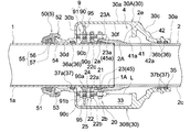
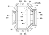
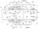
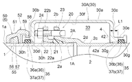
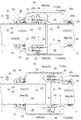
- Perspective view which shows 1st Embodiment of the detachment prevention structure of a pipe connection part Overall cross-sectional view at the time of assembly Overall sectional view at the time of withdrawal Overall cross-sectional view showing bending regulation operation in the detached state Split joint wheel case inner view Front view of the tilt control unit of the first embodiment Front view of a main part showing another connection structure of the tilt control part of the first embodiment Front view of the tilt control unit of the second embodiment Overall sectional view at the time of assembly showing the second embodiment of the disconnection prevention structure of the pipe connection portion.
- Overall vertical cross-sectional view at the time of withdrawal Overall sectional view at the time of assembly showing the third embodiment of the disconnection prevention structure of the pipe connection portion.
- Overall sectional view at the time of assembly showing the tenth embodiment of the disconnection prevention structure of the pipe connection portion.
- First Embodiment 1 to 4 show a disconnection prevention structure of a pipe connection portion used in a fluid transportation piping system.
- the insertion port 1A of the fluid pipe 1 which is an example of one pipe portion
- the receiving port 2A of the fluid pipe 2 which is an example of the other pipe portion
- the joint ring 30 having a split structure that surrounds the fitting connection portion 20 in a sealed state is exteriorized over both fluid pipes 1 and 2. As shown in FIGS.
- the socket 2A and the insertion port 1A are disconnected from each other at the portions of the joint ring 30 and the other fluid pipe 2 on the receiving port 2A side facing each other in the pipe axis direction.
- a first detachment blocking unit 4 is provided, which allows the relative detachment movement to the detached state and prevents the relative detachment movement of the receiving port 2A and the joint ring 30 in the detached state from contacting with each other.
- the insertion port 1A of the fluid pipe 1 is provided with a second detachment prevention portion 5 having a divided structure.
- the second detachment preventing portion 5 is a connecting portion 52 fixedly connected to the pipe support portion 30d on one end side in the pipe axis direction of the joint ring 30, and an insertion port 1A for the pipe support portion 30d on one end side of the joint ring 30.
- the retaining portion 55 is provided so that the retaining resistance with the outer peripheral surface 1a of the insertion port 1A increases with the detachment movement of the insertion port 1A.
- a tilt regulating portion 9 for restricting the tilt of the insertion port 1A with respect to the pipe support portion 30d on one end side of the joint ring 30 is provided in a detached state in which the receiving port 2A and the insertion port 1A are disconnected. Has been done.
- the fluid pipes 1 and 2 have been mentioned as an example of the pipe portion, but there have been various types of pipe portions conventionally.
- it constitutes a branch pipe portion of a split T-shaped pipe whose exterior is fixed to the fluid pipe in a sealed state, a branch pipe portion integrally protruding from the fluid pipe, and a part of fluid equipment.
- the pipe part and the like can be mentioned.
- the fluid pipes 1 and 2 of the present embodiment are ductile cast iron pipes constituting a water pipe for transporting clean water, which is an example of a fluid, but other cast iron pipes, steel pipes, and the like can be used.
- the fluid, industrial water, gas, etc. can be mentioned in addition to clean water.
- the fitting connection portion 20 between the insertion port 1A of one fluid pipe 1 and the receiving port 2A of the other fluid pipe 2 is composed of a K-shaped mechanical joint.
- a first seal member 21 such as a rubber ring is mounted between the outer peripheral surface 1a of the insertion port 1A and the tapered inner peripheral surface 2a of the receiving port 2A.
- a push ring 22 provided with a pressing portion 22a capable of pressing the first seal member 21 from the direction of the pipe axis is exteriorized at the insertion port 1A.
- the flange portion 22b of the push ring 22 and the flange portion 2b of the receiving port 2A are piped by a first fastener 25 such as a plurality of metal T-head bolts 23 and nuts 24 arranged at predetermined intervals in the pipe circumferential direction. It is tightened and connected from the axis direction. By tightening and connecting with the first fastener 25, the first seal member 21 is compressed into a sealed state (watertight state) by the pressing portion 22a of the push ring 22 which is attracted and fixed to the flange portion 2b of the receiving port 2A, and the sealed state is changed. Be maintained.
- a first fastener 25 such as a plurality of metal T-head bolts 23 and nuts 24 arranged at predetermined intervals in the pipe circumferential direction. It is tightened and connected from the axis direction.
- the joint ring 30 is made of cast iron having a two-divided structure that can be freely exteriorized over both fluid pipes 1 and 2 while surrounding the fitting connection portion 20 of both fluid pipes 1 and 2. It is composed of both split joint wheel cases 30A and 30B. As shown in FIGS. 2 and 5, the two split joint ring cases 30A and 30B are configured to have the same shape.
- the joint ring 30 has a cylindrical peripheral wall portion 30a having a diameter larger than that of the receiving port 2A, and an annular side wall portion integrally extending inward in the radial direction from both ends of the peripheral wall portion 30a in the pipe axis direction.
- the main configurations are 30b and 30c, and cylindrical pipe support portions 30d and 30e extending outward from the inner diameter side ends of the side wall portions 30b and 30c along the pipe axis direction.
- the side wall portion 30b on one end side on the insertion port 1A side is formed as a vertical side wall portion orthogonal to or substantially orthogonal to the tube axis.
- the side wall portion 30c on the other end side, which is on the receiving port 2A side, is configured as a tapered side wall portion having a smaller diameter toward the pipe support portion 30e side continuous with the side wall portion 30c.
- connecting flange portions 30C projecting outward in the horizontal direction are integrally formed at both ends of the joint ring 30 divided joint ring cases 30A and 30B in the pipe circumferential direction. ing.
- the connecting flange portions 30C of the two split joint wheel cases 30A and 30B are fixedly connected to each other in a sealed state (watertight state) by tightening the second fastener 34 such as the bolt 31 and the nut 32.
- the two split joint wheel cases 30A and 30B have the outer peripheral surfaces 1a of both fluid pipes 1 and 2 including the inner peripheral surface 30f (see FIG. 2) of the joint ring 30 and the fitting connection portion 20.
- a seal portion 35 (see FIG. 2) that seals the surrounding space 33 formed between the 2c and the outside with respect to the outside is provided.
- the seal portion 35 is provided with a second seal member 37 such as an annular gasket in the annular seal holding grooves 36 formed in each of the two split joint ring cases 30A and 30B. It is composed of.
- the seal holding groove 36 includes a first circumferential groove 36a formed on the inner surface of the pipe support portion 30d facing the semi-peripheral surface of the insertion port 1A and the receiving port 2A.
- Two second circumferential groove 36b and first and second circumferential groove 36a which are formed on the inner surface of the pipe support portion 30e facing the semi-peripheral surface at intervals in the pipe axis direction.
- a pipe axial groove portion 36c formed along a dividing surface of both connecting flange portions 30C in a state of communicating with the circumferential end portion of the 36b is provided.
- the second seal member 37 has a first circumferential seal portion 37a attached to the first circumferential groove 36a and a second seal member 37 attached to the second circumferential groove 36b of the two articles.
- the circumferential seal portion 37b and the tubular axial seal portion (not shown) mounted on the tubular axial groove portion 36c are integrally molded. Then, the pipe axial direction seal portions of both second seal members 37 come into contact with each other in a sealed state (watertight state) from the pipe radial direction between the divided surfaces of both connecting flange portions 30C.
- the first circumferential seal portion 37a and the second circumferential seal portion 37b of both second seal members 37 are formed on the outer peripheral surfaces 1a and 2c of both fluid pipes 1 and 2 at both pipe support portions 30d and 30e of the joint ring 30. Contact in a sealed state along the circumferential direction of the pipe.
- the first detachment preventing portion 4 is the inner peripheral surface 30f between the pipe support portions 30d and 30e of the split joint ring cases 30A and 30B, and is in the direction other than the pipe axis direction.
- a semi-circular ring projecting inward in the pipe radial direction from the pipe axis direction to a position where it can abut the head 23A of the plurality of T-head bolts 23 of the first fastener 25 at the portion displaced toward the end side.
- the detachment prevention wall portion 41 is integrally formed.
- the detachment prevention wall portion 41 is formed at the boundary portion between the peripheral wall portion 30a and the tapered side wall portion 30c on the inner peripheral surfaces 30f of the two split joint ring cases 30A and 30B.
- the side surfaces of the detachment prevention wall portion 41 are in a detached state due to the contact with the head 23A of the T-head bolt 23. It is configured on the contact surface 41a that prevents the relative detachment movement of the receiving port 2A and the joint ring 30 from contacting each other.
- a plurality of metal T-head bolts 23 arranged at predetermined intervals in the circumferential direction of the pipe are also configured as a contact member 45 fixed to the receiving port 2A side, and the head 23A of each T-head bolt 23 is configured.
- the contact surface 23a which is a flat top surface, is formed on the contact surface 45a of the contact member 45.
- Each of the contact surface 41a of the detachment prevention wall portion 41 and the contact surface 45a of the contact member 45 composed of the contact surface 23a of the head portion 23A of each T-head bolt 23 is orthogonal to the pipe axis. It is formed on the orthogonal planes.
- the contact member 45 is composed of the contact surface 41a of the detachment prevention wall portion 41 in the joint ring 30 and the contact surface 23a of the head 23A of each T head bolt 23 fixed to the receiving port 2A side.
- the contact surface 45a comes into contact with the pipe axis from the direction of the pipe axis, and the further detachment movement between the receiving port 2A of the fluid pipe 2 and the joint ring 30 is prevented.
- the detachment prevention wall portion 41 in the joint ring 30 and the contact surface 45a of the contact member 45 are formed on orthogonal surfaces orthogonal to the pipe axis, the detachment prevention wall The contact surface 41a of the portion 41 and the contact surface 45a of the contact member 45 are in a surface contact state along the orthogonal direction. As a result, the withdrawal force can be reliably received and the withdrawal prevention effect can be improved. Further, since the push-opening force of the split joints acting on the split joints 30A and 30B of the joint rings 30 is not generated at the time of contact, the sealing performance of the split joints 30A and 30B is reduced. It can be suppressed.
- the initial assembly state is a state in which the tip of the T-head bolt 23 of the fitting connection portion 20 is in contact with the inner surface of the side wall portion 30b on one end side of the joint ring 30.
- the state in which the contact surface 23a of the head 23A of the T-head bolt 23 is in contact with the contact surface 41a of the detachment prevention wall portion 41 in the joint ring 30 is the maximum detachment movement state.
- the maximum detachment movement state Become.
- the distance from the contact surface 23a of the head 23A of the T-head bolt 23 to the contact surface 41a of the detachment prevention wall portion 41 in the initial assembly state becomes the maximum detachment movement distance L.
- the connection between the insertion port 1A of one fluid tube 1 and the socket 2A of the other fluid tube 2 is released.
- the second detachment prevention portion 5 is composed of a seismic retrofitting metal fitting 50 having a divided structure.
- the seismic retrofitting metal fitting 50 is divided into two in the pipe circumferential direction, and a pair of metal split holding members 51 that are detachably held and fixed to the insertion port 1A of one of the fluid pipes 1 from the pipe radial direction. Is provided.
- the pair of split holding members 51 inserts the fluid pipe 1 by tightening and connecting the flange portions 51A provided at both ends in the pipe circumferential direction with a third fastener 47 such as a bolt 48 and a nut 49. It is firmly sandwiched and fixed to the mouth 1A.
- the connecting portion 52 of the seismic retrofitting metal fitting 50 has an annular engaging protrusion 53 protruding from the outer peripheral surface of the pipe supporting portion 30d on one end side of the joint ring 30, and a pipe radial direction outside the engaging protrusion 53. It includes an engaging recess 54 that can be engaged and disengaged from the side. Among them, the engaging recess 54 is formed as an opening inward in the pipe radial direction at a portion of each of the divided sandwiching members 51 that integrally projects from the middle portion in the pipe circumferential direction along the pipe axis direction.
- the engaging recess 54 integrally formed in the two split holding members 51 is formed at one end of the joint ring 30.
- the engagement protrusion 53 of the pipe support portion 30d on the side is engaged from the outer side in the pipe radial direction, and in this state, the flange portions 51A of the two split holding members 51 are engaged with each other with the bolt 48 and the nut 49 of the third fastener 47. Tighten and connect with.
- gap regulation bolts 58 that come into contact with the outer peripheral surface 1a of the insertion port 1A from the pipe radial direction are screwed into a plurality of pipe support portions 30d on one end side of the joint ring 30 in the pipe circumferential direction. There is. By the screwing operation of the plurality of gap regulating bolts 58, the annular gap between the inner peripheral surface of the pipe support portion 30d on one end side and the outer peripheral surface 1a of the insertion port 1A is constantly regulated.
- the retaining portion 55 of the seismic retrofitting metal fitting 50 includes a claw storage portion 56 formed on the inner peripheral surface of the two-split holding member 51 and opening inward in the radial direction, and the claw.
- a claw member 57 that is movably accommodated inward in the pipe radial direction is provided in the accommodating portion 56.
- On the inner surface of the claw member 57 a plurality of rows of sharp tapered blades along the circumferential direction of the pipe that can bite into the outer peripheral surface 1a of the insertion port 1A are formed.
- the outer surface of the claw member 57 and the ceiling surface of the claw storage portion 56 are housed in the claw storage portion 56 in a state of biting into the claw storage portion 56 of the double-split holding member 51 and the outer peripheral surface 1a of the insertion port 1A. It is formed on an inclined surface that bites and moves the claw member 57 inward in the radial direction with the relative detachment movement in the direction of the tube axis.
- the connecting portion 52 of the seismic retrofitting metal fitting 50 having a split structure provided in the insertion port 1A is fixedly connected to the pipe support portion 30d on one end side of the joint ring 30. The connection between the joint ring 30 and the seismic retrofitting metal fitting 50 is firmly maintained.
- the claw member 57 of the retaining portion 55 of the seismic retrofitting metal fitting 50 is pulled out by biting into the outer peripheral surface 1a of the insertion port 1A as the insertion port 1A detaches from the pipe support portion 30d on one end side of the joint ring 30. Stop resistance increases. Therefore, as a whole, the insertion port 1A of one of the fluid pipes 1 and the pipe support portion 30d on one end side of the joint ring 30 are integrally and firmly fixedly connected via the seismic retrofitting metal fitting 50. As a result, as shown in FIG.
- the receiving port 2A moves out of the pipe support portion 30e on the other end side of the joint ring 30 and the joint ring 30 It is possible to firmly prevent the insertion port 1A from moving out of the pipe support portion 30d on one end side.
- the pipe support portion 30d on one end side of the joint ring 30 and the retaining portion 55 of the seismic retrofitting metal fitting 50 support two locations at the insertion port 1A of the fluid pipe 1 at intervals in the pipe axis direction. As shown in 3, when the insertion port 1A and the receiving port 2A are disconnected from each other, the bending of the insertion port 1A and the pipe support portion 30d on one end side of the joint ring 30 can be suppressed.
- the tilt regulating unit 9 is inserted in a state in which the insertion port 1A of one fluid pipe 1 and the receiving port 2A of the other fluid pipe 2 are fitted and connected to each other and in a detached state.
- a tilt restricting body 90 externally attached to 1A and a fixed connecting portion 91 for fixing and connecting the tilt regulating body 90 to the receiving port 2A are provided.
- the tilt restricting body 90 is integrally formed with a tilt regulating cylinder 90b having an inner diameter slightly larger than the outer diameter of the insertion port 1A, and a tilt regulating cylinder 90b radially outward from the outer peripheral surface of the tilt regulating cylinder 90b. It has a connecting flange portion 90c that projects in a symmetrical manner.
- the tilt regulating surface 90a of the tilt restricting body 90 has an insertion port 1A with respect to the pipe support portion 30d on one end side of the joint ring 30 in a detached state in which the insertion port 1A and the receiving port 2A are disconnected. At the time of tilting, it contacts the outer surface of the end portion of the insertion port 1A to regulate further tilting.
- the tilt restricting body 90 is divided into two in the circumferential direction of the pipe, and is detachably attached to the insertion port 1A from the radial direction of the pipe. It is composed of regulating members 90A and 90B.
- the pair of split tilt regulating members 90A and 90B are inserted by tightening and connecting the connecting pieces 90d provided at both ends in the pipe circumferential direction with a fourth fastener 92 such as a bolt 93 and a nut 94. It is formed in an annular shape along the outer peripheral surface 1a of 1A.
- the connecting flange portions 90c of the split tilt regulating members 90A and 90B are on one end side of the joint ring 30 in a detached state in which the insertion port 1A and the receiving port 2A are disconnected.
- a tilt regulating protrusion 95 is provided to regulate further tilting of the insertion port 1A by abutting against the inner surface of the joint ring 30 as the insertion port 1A tilts with respect to the pipe support portion 30d.
- the tilt restricting protrusion 95 is provided at one or a plurality of connecting flange portions 90c.
- the tilt regulating protrusion 95 is formed so as to protrude outward in the pipe radial direction from two locations in the circumferential direction of each connecting flange portion 90c.
- the tilt regulating tube 90b of the split tilt regulating members 90A and 90B has a taper formed between the tapered inner peripheral surface 22c of the push ring 22 and the outer peripheral surface 1a of the insertion port 1A.
- An engaging protrusion 90e that engages with the shape gap from the direction of the tube axis is projected.
- the engaging protrusions 90e of the two split tilt regulating members 90A and 90B have a tapered inner peripheral surface 22c of the push ring 22 even when the insertion port 1A and the receiving port 2A are disconnected from each other. Engagement with is maintained.
- the fixed connecting portion 91 of the tilt regulating portion 9 is composed of the first fastener 25 of the fitting connecting portion 20. Specifically, a bolt insertion hole through which the tip of the T-head bolt 23 can be inserted into a portion of the connecting flange portion 90c of the two split tilt regulating members 90A and 90B corresponding to each T-head bolt 23 of the first fastener 25. Form 91a.
- a fixed connecting nut 91b is screwed into the tip of the T-head bolt 23 into which the bolt insertion holes 91a of the split tilt regulating members 90A and 90B are inserted. By tightening the fixed connecting nut 91b, the tilt restricting body 90 is fixedly connected to the receiving port 2A.
- the insertion port 1A may tilt with respect to the pipe support portion 30d on one end side of the joint ring 30.
- the outer surface of the end portion of the insertion port 1A abuts on the tilt control surface 90a of the tilt control body 90, and a part of the tilt control protrusion 95 of the tilt control body 90 abuts on the inner surface of the joint ring 30.
- the bent state of the insertion port 1A and the pipe support portion 30d on one end side of the joint ring 30 in the detached state is maintained within an appropriate range, and the sealing performance of the sealing portion 35 in the circumferential direction is reduced.
- the resulting fluid leakage can be suppressed.
- the configuration is not limited to this.
- the first detachment prevention portion 4 will be described with reference to FIGS. 2 and 3, both pipe support portions 30d and 30e of the joint ring 30.
- a thick-walled detachment prevention portion 42 that can be contacted is formed on the other end side of the inner surface between the pipe shafts in the direction of the pipe shaft core, in other words, on the side wall portion 30c on the other end side of the joint ring 30, from the tapered outer peripheral surface portion 2e on the outer peripheral surface 2c of the receiving port 2A and the pipe shaft core direction.
- a thick-walled detachment prevention portion 42 that can be contacted is formed.
- the contact surface 42a of the detachment prevention portion 42 is formed in a tapered shape having the same slope as the tapered outer peripheral surface portion 2e on the outer peripheral surface 2c of the receiving port 2A.
- the first detachment prevention portion 4 when a detachment force due to an earthquake, uneven settlement, or the like acts on the fitting connection portion 20 between the insertion port 1A and the receiving port 2A, the side wall on the other end side of the joint ring 30.
- the contact surface 42a of the detachment blocking portion 42 formed in the portion 30c and the tapered outer peripheral surface portion 2e on the outer peripheral surface 2c of the receiving port 2A can come into contact with each other to prevent further detachment movement of both.
- the contact surface 42a of the detachment prevention portion 42 is formed in a tapered shape having the same slope as the tapered outer peripheral surface portion 2e on the outer peripheral surface 2c of the receiving port 2A, the contact surface 42a of the detachment prevention portion 42a. And the tapered outer peripheral surface portion 2e of the receiving port 2A come into contact with each other in a surface contact state, and the detachment movement of the receiving port 2A and the joint ring 30 can be strongly prevented. Moreover, when the contact surface 42a of the detachment blocking portion 42 abuts on the tapered outer peripheral surface portion 2e of the receiving port 2A, a force is generated to push open the divided surface of the joint ring 30 of the divided structure.
- the contact surface 42a of the detachment preventing portion 42 is formed on the other end side of the joint ring 30 between the two pipe support portions 30d and 30e in the pipe axis direction, so that both pipe support portions 30d.
- the push-opening force becomes smaller by the deviation allowance at which the contact surface 42a of the detachment blocking portion 42 deviates from 30e, and fluid leakage occurs due to a decrease in the sealing property of the seal portion 35 due to the push-opening of the split surface of the joint ring 30. Can be suppressed.
- connection structure of the tilt control body 90 of the first embodiment As shown in FIG. 6, as a first embodiment of the tilt regulating body 90, the connecting pieces 90d provided at both ends of the split tilt regulating members 90A and 90B in the pipe circumferential direction are bolted to each other. It was connected by a fourth fastener 92 such as 93 and a nut 94.
- a fourth fastener 92 such as 93 and a nut 94.
- FIG. 7 may be adopted.
- a second connecting piece 90f that can be polymerized and arranged from the pipe radial direction is integrally formed at each of both ends of the split tilt regulating members 90A and 90B in the pipe circumferential direction.
- a second bolt insertion hole 91c through which the tip of the T-head bolt 23 can be inserted is formed in the second connecting piece 90f of each set to be polymerized.
- the tilt regulating protrusion 95 is configured so that the contact position with respect to the inner surface of the joint ring 30 can be changed in the pipe radial direction.
- the tilt regulating protrusion 95 is screwed into the female screw portion 95A formed at two locations in the circumferential direction of each of the split tilt regulating members 90A and 90B, and the female screw portion 95A from the pipe radial direction. It includes a tilt control bolt 95B and a lock nut 95C for fixing the tilt control bolt 95B whose contact position in the pipe radial direction is adjusted. By screwing the tilt control bolt 95B, the contact position of the joint ring 30 with respect to the inner surface is changed in the pipe radial direction.
- the tilt restricting body 90 having the split structure of the tilt regulating portion 9 is exteriorized to the insertion port 1A, there is a site where the receiving port 2A and the insertion port 1A are bent at the fitting connection portion 20.
- the contact position of the tilt control bolt 95B is set to the pipe diameter according to the measured distance between the tip of the tilt control bolt 95B of the tilt control body 90 and the protrusion contact portion on the inner peripheral surface 30f of the joint ring 30. Can be changed in direction.
- the exterior assembly work of the tilt regulating unit 9 with respect to the insertion port 1A can be efficiently and reliably performed. ..
- the tilt regulating bolt 95B of the tilt regulating body 90 can be accurately brought into contact with the inner surface of the joint ring 30. ..
- the bent state of the insertion port 1A and the pipe support portion 30d on one end side of the joint ring 30 in the detached state is maintained within an appropriate range, which is caused by the local deterioration of the sealing performance of the sealing portion 35 in the circumferential direction. It is possible to suppress the leakage of the fluid. Since the other configurations are the same as the configurations described in the first embodiment, the same numbers as those in the first embodiment are added to the same configuration parts, and the description thereof will be omitted.
- the fitting connection portion 20 between the insertion port 1A of one fluid pipe 1 and the receiving port 2A of the other fluid pipe 2 is T-shaped. It is composed of mechanical joints of. In this T-shaped mechanical joint, the outer peripheral surface 1a of the insertion port 1A is fitted and connected to the receiving port 2A in the annular seal holding groove 60 formed on the inner peripheral surface of the receiving port 2A and opening inward in the radial direction.
- a third seal member 61 such as a rubber ring that is compressed into a sealed state (watertight state) is attached to the surface.
- a tilt regulating unit 9 for regulating the tilt of the insertion port 1A is provided. As shown in FIGS. 11 and 12, the tilt regulating unit 9 is inserted in a state in which the insertion port 1A of one fluid tube 1 and the receiving port 2A of the other fluid tube 2 are fitted and connected and in a detached state.
- a tilt restricting body 90 externally attached to 1A and a fixed connecting portion 91 for fixing and connecting the tilt regulating body 90 to the receiving port 2A are provided.
- the tilt control body 90 has a tilt control surface 90a having an inner diameter slightly larger than the outer diameter of the insertion port 1A. As shown in FIG. 12, the tilt regulating surface 90a is in a detached state in which the insertion port 1A and the receiving port 2A are disconnected, and when the insertion port 1A is tilted with respect to the pipe support portion 30d on one end side of the joint ring 30. It abuts on the outer surface of the end of the insertion slot 1A to regulate further tilting.
- the tilt restricting body 90 is divided into two in the circumferential direction of the pipe, and is detachably attached to the insertion port 1A from the radial direction of the pipe.
- the split tilt regulating members 90C and 90D are provided.
- the pair of second split tilt regulating members 90C and 90D are connected by tightening 90 g of the third connecting pieces provided at both ends in the pipe circumferential direction with a fourth fastener 92 such as a T-head bolt 93A and a nut 94. By doing so, it is formed in an annular shape along the outer peripheral surface 1a of the insertion port 1A.
- both the second split tilt regulating members 90C and 90D have a pipe support portion on one end side of the joint ring 30 in a detached state in which the insertion port 1A and the receiving port 2A are disconnected.
- a tilt regulating protrusion 95 is provided to regulate the further tilt of the insertion port 1A by abutting against the inner surface of the joint ring 30 as the insertion port 1A tilts with respect to 30d.
- the tilt regulating protrusions 95 are provided at one or more locations of the divided tilt regulating members 90A and 90B.
- the tilt regulating protrusion 95 is formed so as to protrude outward from two locations in the circumferential direction of the divided tilt regulating members 90A and 90B along the pipe radial direction.
- the tilt control protrusion 95 is configured so that the contact position of the joint ring 30 with respect to the inner surface can be changed in the pipe radial direction.
- the tilt regulating protrusion 95 is screwed into the female screw portion 95A formed at two locations in the circumferential direction of each of the split tilt regulating members 90A and 90B, and the female screw portion 95A from the pipe radial direction. It includes a tilt control bolt 95B and a lock nut 95C for fixing the tilt control bolt 95B whose contact position in the pipe radial direction is adjusted. By screwing the tilt control bolt 95B, the contact position of the joint ring 30 with respect to the inner surface is changed in the pipe radial direction.
- the fixed connecting portion 91 is provided on the tilt restricting body 90 in a state where it can be engaged and disengaged from the outside in the pipe radial direction with respect to the annular protrusion 2g formed at the end of the outer peripheral surface 2c of the receiving port 2A.
- the third connecting pieces 90g of the second split tilt regulating members 90C and 90D are inserted into the insertion port 1A. It is composed of a fourth fastener 92 that is tightened and fixed in a holding state.
- the socket 2A and the insertion port 1A are disconnected from each other at the portions of the joint ring 30 and the other fluid pipe 2 on the receiving port 2A side in the direction of the tube axis.
- a first detachment blocking unit 4 is provided, which allows the relative detachment movement to the detached state and prevents the relative detachment movement of the receiving port 2A and the joint ring 30 in the detached state from contacting with each other.
- the first detachment prevention portion 4 is the inner peripheral surface 30f between the pipe support portions 30d and 30e of the two split joint ring cases 30A and 30B, and is in the direction other than the pipe axis direction.
- a protruding semicircular ring-shaped detachment prevention wall portion 41 is integrally formed.
- the detachment prevention wall portion 41 is formed at the boundary portion between the peripheral wall portion 30a and the tapered side wall portion 30c on the inner peripheral surfaces 30f of the two split joint ring cases 30A and 30B.
- the side surfaces facing the contact portions 90h of the two second division tilt regulating members 90C and 90D in the direction of the pipe axis are the hit surfaces of the two second division tilt regulating members 90C and 90D. It is configured as a contact surface 41a that prevents the relative detachment movement of the receiving port 2A and the joint ring 30 in the detached state by abutting with the contact portion 90h. Since the other configurations are the same as the configurations described in the first embodiment, the same numbers as those in the first embodiment are added to the same configuration parts, and the description thereof will be omitted.
- [Fourth Embodiment] 14 and 15 show a disconnection prevention structure of a pipe connection portion used in a fluid transportation piping system.
- the insertion port 1A of the fluid pipe 1 which is an example of one pipe portion and the receiving port 2A of the fluid pipe 2 which is an example of the other pipe portion are connected by the fitting connection portion 20.
- the joint ring 30 having a split structure that surrounds the fitting connection portion 20 in a sealed state is exteriorized over both fluid pipes 1 and 2.
- the fitting connection portion 20 is composed of a K-shaped mechanical joint as in the first embodiment. As shown in FIGS.
- the socket 2A and the insertion port 1A are disconnected from each other at the portions of the joint ring 30 and the other fluid pipe 2 on the receiving port 2A side in the direction of the tube axis.
- a first detachment blocking unit 4 is provided, which allows the relative detachment movement to the detached state and prevents the relative detachment movement of the receiving port 2A and the joint ring 30 in the detached state from contacting with each other.
- the insertion port 1A of the fluid pipe 1 is provided with a second detachment prevention portion 5 having a divided structure.
- the second detachment preventing portion 5 is a connecting portion 52 fixedly connected to the pipe support portion 30d on one end side in the pipe axis direction of the joint ring 30, and an insertion port 1A for the pipe support portion 30d on one end side of the joint ring 30.
- the retaining portion 55 is provided so that the retaining resistance with the outer peripheral surface 1a of the insertion port 1A increases with the detachment movement of the insertion port 1A.
- the joint ring 30 is made of cast iron having a two-divided structure that can be freely exteriorized over both fluid pipes 1 and 2 while surrounding the fitting connection portion 20 of both fluid pipes 1 and 2. It is composed of both split joint wheel cases 30A and 30B.
- the joint ring 30 has a cylindrical peripheral wall portion 30a having a diameter larger than that of the receiving port 2A, and an annular side wall portion 30b extending radially inward from both ends of the peripheral wall portion 30a in the pipe axis direction.
- 30c and cylindrical pipe support portions 30d, 30e extending integrally outward from the inner diameter side ends of the side wall portions 30b, 30c along the pipe axis direction are provided as the main configurations. There is.
- connections are made to both ends of the joint ring 30 divided joint ring cases 30A and 30B in the pipe circumferential direction so as to be fixedly connected to each other via a second fastener 34 such as a bolt 31 and a nut 32.
- the flange portion 30C is integrally formed.
- the divided surfaces of the two divided joint ring cases 30A and 30B are between the inner peripheral surface 30f of the joint ring 30 (see FIG. 16) and the outer peripheral surfaces 1a and 2c of both fluid pipes 1 and 2 including the fitting connection portion 20.
- a seal portion 35 (see FIG. 15) is provided to seal the surrounding space 33 formed in the water tightly to the outside. As shown in FIGS.
- the seal portion 35 has a second seal member 37 such as an annular gasket in the annular seal holding groove 36 formed on each of the divided surfaces of the two divided joint ring cases 30A and 30B. It is configured by wearing.
- the second seal members 37 are in watertight contact with each other from the pipe radial direction at both ends of the split joint ring cases 30A and 30B in the pipe circumferential direction, and both are in the pipe support portions 30d and 30e of the joint ring 30. It contacts the outer peripheral surfaces 1a and 2c of the fluid pipes 1 and 2 in a watertight state along the pipe circumferential direction.
- the first detachment preventing portion 4 is on the inner peripheral surface side of the pipe support portion 30e on the other end side of the joint ring 30 in the pipe axis direction and in the pipe support portion 30e.
- the second circumferential groove portion 36b of the seal holding groove 36 formed on the inner peripheral surface and the second circumferential seal portion 37b of the second seal member 37 attached thereto are biased toward the center side in the pipe axis direction of the joint ring 30.
- a detachment prevention portion 42 having an outer peripheral surface 2c of the receiving port 2A and an annular contact surface 42a capable of contacting from the pipe axis direction is formed at the positioned portion.
- the detachment prevention portion 42 is formed to have a diameter smaller than the inner diameter of the partition wall 30g located on both sides of the second circumferential groove portion 36b in the pipe axis direction on the inner peripheral surface of the pipe support portion 30e on the other end side.
- the inner peripheral surface of the detachment blocking portion 42 is formed so as to protrude inward in the radial direction from the inner peripheral surface of the partition wall 30 g located on both sides of the second circumferential groove portion 36b.
- the detachment prevention portion 42 is integrally formed with one partition wall 30g, and has a reinforcing structure in which the thickness in the pipe axis direction from the contact surface 42a of the detachment prevention portion 42 to the second circumferential groove portion 36b of the seal holding groove 36 is also large. It is configured in. Further, the contact surface 42a of the detachment prevention portion 42 is formed at the same or substantially the same inclination angle as the inclination angle of the tapered contact portion 2d of the outer peripheral surface 2c of the receiving port 2A.
- the tip of the T-head bolt 23 of the fitting connection portion 20 is in contact with the inner surface of the side wall portion 30b on one end side of the joint ring 30. It will be in the initial assembly state. Further, as shown in FIG. 17, the contact surface 42a of the detachment blocking portion 42 formed on the pipe support portion 30e on the other end side of the joint ring 30 corresponds to the tapered contact portion 2d of the outer peripheral surface 2c of the receiving port 2A. The state of contact is the maximum detachment movement state. As a result, as shown in FIG.
- the tip of the T-head bolt 23 is in the maximum detached movement state from the tip position of the T-head bolt 23 or the inner surface of the side wall portion 30b on one end side of the joint ring 30 in the initial assembly state.
- the distance to the position is the maximum detachment movement distance L, and in the maximum detachment movement state, the connection between the insertion port 1A of one fluid pipe 1 and the receiving port 2A of the other fluid pipe 2 is released.
- a detaching force due to an earthquake, uneven settlement, or the like acts on the fitting connection portion 20 between the insertion port 1A and the receiving port 2A, and the pipe support portion 30e on the other end side of the joint ring 30 acts.
- the contact surface 42a of the detachment blocking portion 42 formed on the inner peripheral surface side abuts on the tapered contact portion 2d of the outer peripheral surface 2c of the receiving port 2A, a force that pushes open the divided surface of the joint ring 30 of the divided structure. Occurs.
- the detachment prevention portion 42 of the joint ring 30 is formed at a portion deviated from the second circumferential groove portion 36b of the seal holding groove 36 toward the center side in the tube axis direction of the joint ring 30.
- the pushing-opening force is reduced by the amount of the deviation allowance, and it is possible to suppress the occurrence of fluid leakage due to a decrease in the sealing property (decrease in surface pressure) of the seal portion 35 due to the push-opening of the divided surface of the joint ring 30.
- the distance L1 to 36b is the joint ring 30 of the partition walls 30h on both sides in the pipe axis direction in the first circumferential groove 36a of the seal holding groove 36 formed on the inner peripheral surface of the pipe support portion 30d on one end side. It is configured to be larger than the thickness dimension in the pipe axis direction on the inner side partition wall 30h on the center side in the pipe axis direction.
- the thickness dimension corresponding to the distance L1 from the contact surface 42a of the detachment prevention portion 42 of the joint ring 30 to the groove portion 36b in the second circumferential direction of the seal portion 35 is the pipe on one end side of the joint ring 30. Since the support portion 30d is configured to be larger than the thickness dimension of the partition wall 30h of the first circumferential groove portion 36a in the pipe axis direction, the detachment prevention portion 42 that abuts on the outer peripheral surface 2c of the receiving port 2A is made sturdy. Can be configured.
- the second detachment prevention portion 5 is composed of the seismic retrofitting metal fitting 50 having a divided structure.
- the connecting portion 52 of the seismic retrofitting metal fitting 50 has an annular engaging recess 58 formed on the outer peripheral surface of the pipe supporting portion 30d on one end side and opening outward in the radial direction, and a pipe radial direction with respect to the engaging recess 58. It is composed of an engaging protrusion 59 that is engageable and disengaged from the outside.
- the engaging protrusions 59 are integrally formed so as to protrude from a plurality of locations in the pipe circumferential direction of the bipartite holding member 51 along the pipe axis direction.
- the engaging protrusion 59 integrally formed with the two split holding members 51 is supported by the pipe on one end side.
- the flange portions 51A of the two split sandwiching members 51 are fastened and connected with a third fastener 47 such as a bolt 48 and a nut 49.
- the retaining portion 55 of the seismic retrofitting metal fitting 50 has the same structure as the retaining portion 55 described in the first embodiment. Therefore, the same number as that of the first embodiment is added to the same configuration portion, and the description thereof will be omitted.
- the fitting connection portion 20 between the insertion port 1A of one fluid pipe 1 and the receiving port 2A of the other fluid pipe 2 has the same T-shape as in the third embodiment. It consists of a mechanical joint. Since the other configurations are the same as the configurations described in the fourth embodiment, the same numbers as those in the fourth embodiment are added to the same configuration parts, and the description thereof will be omitted.
- the fitting connection portion 20 between the insertion port 1A of one fluid pipe 1 and the receiving port 2A of the other fluid pipe 2 is composed of a T-shaped mechanical joint.
- an improvement of the first detachment prevention portion 4 for preventing the relative detachment movement of the other fluid pipe 2 from the receiving port 2A and the joint ring 30 by contact with each other is shown.
- the outer peripheral surface 2c of the socket 2A is located at a portion displaced toward the center of the joint ring 30 in the pipe axis direction from the second circumferential groove portion 36b and the second circumferential seal portion 37b of the second seal member 37 attached thereto.
- a detachment prevention portion 42 having an annular contact surface 42a capable of contacting from the tapered contact portion 2d and the pipe axis direction is formed.
- the detachment prevention portion 42 On the inner peripheral surface of the pipe support portion 30e on the other end side of the joint ring 30, and at a portion deviated from the detachment prevention portion 42 toward the center of the joint ring 30 in the pipe axis direction, the detachment prevention portion 42 is applied.
- An annular elastic sealing material 43 is provided to seal between the contact surface 42a and the outer peripheral surface 2c of the receiving port 2A in a state where the contact surface 42a is in contact with the tapered contact portion 2d of the outer peripheral surface 2c of the receiving port 2A.
- the second seal holding groove 44 for holding the contact surface 42a of the detachment preventing portion 42 and the elastic sealing material 43 is formed on the inner peripheral surface of the side wall portion 30c on the other end side of the joint ring 30, and the side wall portion on the other end side.
- the thickness of the 30c in the tube axis direction is larger than the thickness of the side wall portion 30b on one end side of the joint ring 30 in the tube axis direction (see FIGS. 15 in the fourth embodiment and FIG. 18 in the fifth embodiment). Has been done.
- the elastic sealing material 43 provided at the portion deviated from the contact surface 42a of the detachment preventing portion 42 toward the center side in the tube axis direction of the joint ring 30 seals between the receiving port 2A and the outer peripheral surface 2c. Therefore, the fluid does not flow into the damaged portion of the covering protective layer, and the progress of corrosion of the socket 2A at the damaged portion of the covering protective layer can be suppressed. Since the other configurations are the same as the configurations described in the fifth embodiment, the same numbers as those in the fifth embodiment are added to the same configuration parts, and the description thereof will be omitted.
- the fitting connection portion 20 between the insertion port 1A of one fluid pipe 1 and the receiving port 2A of the other fluid pipe 2 is composed of a K-shaped mechanical joint. ..
- an improvement of the first detachment prevention portion 4 for preventing the relative detachment movement of the other fluid pipe 2 from the receiving port 2A and the joint ring 30 by contact with each other is shown.
- the first detachment prevention portion 4 of this embodiment is a plurality of metal T-heads arranged at predetermined intervals in the circumferential direction of the pipe among the constituent members of the K-shaped mechanical joint constituting the fitting connection portion 20.
- the bolt 23 is also configured as a contact member 45 fixed to the receiving port 2A side.
- the contact surface 23a which is the flat top surface of the head portion 23A of each T-head bolt 23, is formed on the contact surface 45a of the contact member 45.
- the inner surface portion facing the head portion 23A of each T head bolt 23 in the pipe axis direction is configured as the contact surface 46.
- Each of the contact surface 46 formed on the inner surface of the side wall portion 30c and the contact surface 23a of the head portion 23A of each T-head bolt 23 is formed as an orthogonal surface orthogonal to the pipe axis.
- the detachment force can be reliably received and the detachment prevention effect can be improved. Since the other configurations are the same as the configurations described in the fourth embodiment, the same numbers as those in the fourth embodiment are added to the same configuration parts, and the description thereof will be omitted.
- the flat contact surface 23a of the head 23A of each T-head bolt 23 is also configured as the contact surface 45a of the contact member 45, as shown in FIG. 21A.
- a contact member 45 having a contact surface 46 of the side wall portion 30c of the joint ring 30 and a contact surface 45a capable of contacting from the pipe axis direction is integrally formed on the head portion 23A of each T-head bolt 23. May be carried out.
- the contact surface 46 of the joint ring 30 and the contact surface 45a of the contact member 45 on each T-head bolt 23 on the receiving port 2A side are formed on orthogonal surfaces orthogonal to the pipe axis. ..
- the contact surface 46 of the joint ring 30 and the contact surface 45a of the contact member 45 in each T-head bolt 23 come into contact with each other, and the detachment force can be reliably received to improve the detachment prevention effect.
- the head portion 23A of each T-head bolt 23 is provided with a contact surface 46 of the side wall portion 30c of the joint ring 30 and a contact surface 45a capable of contacting from the pipe axis direction.
- the abutting member 45 provided may be fitted and fixed as an attachment.
- the contact surface 46 of the joint ring 30 and the contact surface 45a of the contact member 45B of each T-head bolt 23 on the receiving port 2A side are formed on orthogonal surfaces orthogonal to the pipe axis. ..
- the contact surface 46 of the joint ring 30 and the contact surface 45a of the contact member 45B of each T-head bolt 23 come into contact with each other, and the detachment force can be reliably received to improve the detachment prevention effect.
- the fitting connection portion 20 between the insertion port 1A of one fluid pipe 1 and the receiving port 2A of the other fluid pipe 2 is composed of a T-shaped mechanical joint. ..
- an improvement of the first detachment prevention portion 4 for preventing the relative detachment movement of the other fluid pipe 2 from the receiving port 2A and the joint ring 30 by contact with each other is shown.
- the first detachment prevention unit 4 of this embodiment is an example of the contact member 45 fixed to the receiving port 2A side of the other fluid pipe 2 from the outside in the pipe radial direction with respect to the receiving port 2A of the fluid pipe 2.
- a metal contact band 70 having a split structure (two split structure in the embodiment) that is held and fixed is used.
- the contact band 70 is provided with an annular first positioning portion 70b that abuts on the end surface of the receiving port 2A on the connection port side and a second positioning portion 70c that abuts on the tapered portion of the outer peripheral surface 2c of the receiving port 2A. Has been done. Therefore, in a state where the contact band 70 is tightened and fixed to the outer peripheral surface of the receiving port 2A, the first positioning portion 70b and the second positioning portion 70c prevent the contact band 70 from moving in the tube axis direction. ..
- the tip surface 70a of the second positioning portion 70c of the contact band 70 is formed on the contact surface 45a of the contact member 45.
- the inner surface portion facing the tip surface 70a of the second positioning portion 45c of the contact band 70 in the pipe axis direction abuts. It is configured on the surface 46.
- the contact surface 46 of the joint ring 30 and the tip surface 70a of the contact band 70 fixed to the receiving port 2A are formed on orthogonal surfaces orthogonal to the pipe axis.
- the contact surface 46 of the joint ring 30 and the contact surface 45a of the contact band 70 come into contact with each other, and the detachment force can be reliably received to improve the detachment prevention effect. Since the other configurations are the same as the configurations described in the fourth embodiment, the same numbers as those in the fourth embodiment are added to the same configuration parts, and the description thereof will be omitted.
- the fitting connection portion 20 between the insertion port 1A of one fluid pipe 1 and the receiving port 2A of the other fluid pipe 2 is composed of a K-shaped mechanical joint. ..
- an improvement of the first detachment prevention portion 4 for abutting and preventing the relative detachment movement of the other fluid pipe 2 between the receiving port 2A and the joint ring 30 above a certain level is shown.
- the first detachment prevention portion 4 of this embodiment is an example of the contact member 45 fixed to the receiving port 2A side of the other fluid pipe 2, and is an example of the contact member 45, which is from the outside in the pipe radial direction with respect to the flange portion 2b of the receiving port 2A.
- a metal receiving band 71 that is held and fixed in an engaged state is used.
- the tip surface 71a of the receiving band 71 is formed on the contact surface 45a of the contact member 45.
- the inner surface portion facing the tip surface 71a of the receiving band 71 in the tube axis direction is configured as the contact surface 46. There is.
- each of the contact surface 46 of the joint ring 30 and the tip surface 71a of the socket band 71 fixed to the socket 2A are formed as orthogonal planes orthogonal to the pipe axis.
- the contact surface 46 of the joint ring 30 and the contact surface 45a of the receiving band 71 come into contact with each other, and the detaching force can be reliably received to improve the detachment preventing effect. Since the other configurations are the same as the configurations described in the fourth embodiment, the same numbers as those in the fourth embodiment are added to the same configuration parts, and the description thereof will be omitted.
- the fitting connection portion 20 between the insertion port 1A of one fluid pipe 1 and the receiving port 2A of the other fluid pipe 2 is composed of a K-shaped mechanical joint. ..
- a seismic retrofitting metal fitting having a split structure in which the insertion port 1A of one fluid pipe 1 and the pipe support portion 30d on one end side of the joint ring 30 in the pipe axis direction are integrally fixedly connected. Shows 50 improvements.
- the first circumferential direction groove portion 36a of the seal holding groove 36 formed on the inner peripheral surface thereof and the groove portion 36a in the first circumferential direction.
- An extension pipe support portion 30j having an annular space that opens inward in the radial direction is integrally formed on the end portion side located on the seismic retrofitting metal fitting 50 side with respect to the first circumferential direction seal portion 37a attached thereto.
- An annular engaging recess 58 that opens radially outward is formed on the outer peripheral surface of the pipe support portion 30d on one end side including the extension pipe support portion 30j.
- the engaging projection 59 integrally formed with the double-split holding member 51 of the seismic retrofitting metal fitting 50 is outside the pipe radial direction at the outer end side portion of the range corresponding to the extension pipe support portion 30j. Engage from the side.
- the engagement position of the seismic retrofitting metal fitting 50 with the pipe support portion 30d on one end side of the joint ring 30 by the engagement protrusion 59 is the seal holding groove 36 formed on the inner peripheral surface of the pipe support portion 30d. It is separated from the first circumferential direction groove portion 36a of the above and the first circumferential direction seal portion 37a of the second seal member 37 attached thereto to the outer end side. Therefore, as shown in FIG. 17, bending of the insertion port 1A and the pipe support portion 30d on one end side of the joint ring 30 can be suppressed in the detached state in which the insertion port 1A and the receiving port 2A are disconnected. ..
- the fitting connection portion 20 between the insertion port 1A of one fluid pipe 1 and the receiving port 2A of the other fluid pipe 2 is composed of a K-shaped mechanical joint. ..
- an improvement of the first detachment prevention portion 4 for preventing the relative detachment movement of the other fluid pipe 2 from the receiving port 2A and the joint ring 30 by contact with each other is shown.
- a metal holding ring 80 having a split structure (in the embodiment, a two-split structure) that can be detachably held and fixed from the outside in the pipe radial direction with respect to the bent portion extending over the outer peripheral surface portion 2f is used.
- the holding ring 80 is provided with a semicircular split ring 80A that is split into two in the circumferential direction of the pipe.
- the pair of split rings 80A are firmly sandwiched and fixed to the bent portion of the receiving port 2A by tightening and connecting the connecting pieces 80B provided at both ends in the pipe circumferential direction with bolts 81.
- One end surface 80a of the holding ring 80 in the tube axis direction is configured as a tapered end surface that abuts on the tapered outer peripheral surface portion 2e on the outer peripheral surface 2c of the receiving port 2A in a surface contact state.
- the other end surface 80b of the holding ring 80 in the tube axis direction includes the other end surface of the split ring 80A in the tube axis direction and the other end surface of the connecting piece 80B in the tube axis direction, and the contact surface of the contact member 45. It is configured in 45a.
- the inner surface of the side wall portion 30c on the other end side of the joint ring 30 in the direction of the tube axis is formed as an abutting surface 46 capable of contacting the other end surface 80b of the holding ring 80 from the direction of the tube axis.
- the contact surface 46 formed by the inner surface of the side wall portion 30c of the joint ring 30 and the contact surface 45a formed by the other end surface 80b of the holding ring 80 are formed on orthogonal surfaces orthogonal to the pipe axis. ing.
- the detachment force can be firmly received by this contact. Nevertheless, since the contact surface 46 of the joint ring 30 and the contact surface 45a formed by the other end surface 80b of the holding ring 80 are in a surface contact state along the direction orthogonal to the pipe axis, the joint ring is in contact with the joint ring. By reducing the pushing-opening force of the split joint portion acting on the joint ring 30, it is possible to suppress a decrease in sealing performance (decrease in the surface pressure of the second seal member 37) at the split joint portion of the joint ring 30. Since the other configurations are the same as the configurations described in the fourth embodiment, the same numbers as those in the fourth embodiment are added to the same configuration parts, and the description thereof will be omitted.
- the tilt restrictor 90 is tilted by abutting the outer surface of the insertion port 1A that tilts with respect to the pipe support portion 30d on one end side of the joint ring 30.
- the tilt regulation surface 90a and the inner surface of the joint ring 30 are abutted with the inclination of the insertion port 1A with respect to the pipe support portion 30d on one end side of the joint ring 30, thereby restricting further inclination of the insertion port 1A.
- a tilt-regulating protrusion 95 and a tilt-regulating protrusion 95 are provided.
- the present invention is not limited to this configuration, and for example, it may be carried out only on one of the tilt regulating surfaces 90a or the tilt regulating protrusion 95.
- the contact position of the joint ring 30 with respect to the inner surface is changed in the pipe radial direction by the screwing operation of the tilt regulating bolt 95B.
- the present invention is not limited to this configuration, and for example, a plurality of tilt regulating protrusions 95 having different lengths in the pipe radial direction may be selectively replaced with respect to the tilt regulating body 90 to tilt. By replacing the regulating protrusion 95, the contact position of the joint ring 30 with respect to the inner surface may be changed in the pipe radial direction.
- the present invention reliably prevents the insertion and the receiving port from moving apart with respect to the joint ring while improving the absorption capacity for the disconnection force, and is in a bent state between the insertion and the pipe support portion on one end side of the joint ring.
Landscapes
- Engineering & Computer Science (AREA)
- General Engineering & Computer Science (AREA)
- Mechanical Engineering (AREA)
- Joints With Sleeves (AREA)
- Joints Allowing Movement (AREA)
Abstract
La présente invention permet de prévenir de manière fiable le mouvement de séparation d'une ouverture d'insertion et d'une ouverture de réception par rapport à un collier tout en améliorant la capacité d'absorption de force de séparation, et de maintenir l'état plié de l'ouverture d'insertion et une section de support de tuyau sur un côté du collier dans une plage appropriée. Un collier (30), qui présente une structure divisée et entoure une partie de contre-raccordement (20) d'une ouverture d'insertion (1A) et d'une ouverture de réception (2A) dans un état étanche, est ajusté à l'extérieur des deux sections de tuyau (1, 2). Une première partie de prévention de séparation (4), destinée à venir en butée et à empêcher un degré fixe ou plus de mouvement de séparation relatif de l'ouverture de réception (2A) et du collier (30), est disposée à un emplacement où le collier (30) et l'ouverture de réception (2A) se font face, et une seconde partie de prévention de séparation (5), munie d'une partie de retenue (55) dont la résistance à l'arrachement entre la surface circonférentielle externe de l'ouverture d'insertion (1A) et la partie de retenue augmente conjointement avec le mouvement de séparation de l'ouverture d'insertion (1A), est disposée sur une section de support de tuyau (30d) sur un côté du collier (30) dans la direction axiale de tuyau.
Priority Applications (4)
| Application Number | Priority Date | Filing Date | Title |
|---|---|---|---|
| EP19934174.4A EP3988832B1 (fr) | 2019-06-20 | 2019-06-20 | Structure de prévention de séparation pour partie de raccordement de tuyau |
| CN201980097437.2A CN113939682B (zh) | 2019-06-20 | 2019-06-20 | 管连接部的脱离防止构造 |
| US17/601,789 US12031649B2 (en) | 2019-06-20 | 2019-06-20 | Disengagement prevention structure for pipe connecting portion |
| PCT/JP2019/024476 WO2020255325A1 (fr) | 2019-06-20 | 2019-06-20 | Structure de prévention de séparation pour partie de raccordement de tuyau |
Applications Claiming Priority (1)
| Application Number | Priority Date | Filing Date | Title |
|---|---|---|---|
| PCT/JP2019/024476 WO2020255325A1 (fr) | 2019-06-20 | 2019-06-20 | Structure de prévention de séparation pour partie de raccordement de tuyau |
Publications (1)
| Publication Number | Publication Date |
|---|---|
| WO2020255325A1 true WO2020255325A1 (fr) | 2020-12-24 |
Family
ID=74040367
Family Applications (1)
| Application Number | Title | Priority Date | Filing Date |
|---|---|---|---|
| PCT/JP2019/024476 Ceased WO2020255325A1 (fr) | 2019-06-20 | 2019-06-20 | Structure de prévention de séparation pour partie de raccordement de tuyau |
Country Status (4)
| Country | Link |
|---|---|
| US (1) | US12031649B2 (fr) |
| EP (1) | EP3988832B1 (fr) |
| CN (1) | CN113939682B (fr) |
| WO (1) | WO2020255325A1 (fr) |
Cited By (1)
| Publication number | Priority date | Publication date | Assignee | Title |
|---|---|---|---|---|
| CN117571273A (zh) * | 2023-10-18 | 2024-02-20 | 上海申华声学装备有限公司 | 一种消声器的检测实验室及检测方法 |
Families Citing this family (1)
| Publication number | Priority date | Publication date | Assignee | Title |
|---|---|---|---|---|
| USD1070021S1 (en) * | 2023-12-15 | 2025-04-08 | Stuart G. Goldsberry | Underground irrigation equipment protective device |
Citations (2)
| Publication number | Priority date | Publication date | Assignee | Title |
|---|---|---|---|---|
| JP2001187996A (ja) * | 1999-12-28 | 2001-07-10 | Suido Gijutsu Kaihatsu Kiko:Kk | 管接続部用補強継手 |
| JP2016080129A (ja) * | 2014-10-21 | 2016-05-16 | コスモ工機株式会社 | 離脱防止装置 |
Family Cites Families (19)
| Publication number | Priority date | Publication date | Assignee | Title |
|---|---|---|---|---|
| JPS58191486U (ja) | 1982-06-15 | 1983-12-20 | 新日本製鐵株式会社 | 伸縮管継手における漏洩検知装置付き2重シ−ル装置 |
| US4506919A (en) * | 1983-01-03 | 1985-03-26 | Amsted Industries Incorporated | Restrained mechanical pipe joint |
| JPS6359290U (fr) | 1986-10-06 | 1988-04-20 | ||
| AU669967B2 (en) * | 1993-01-22 | 1996-06-27 | Hans Oetiker Ag Maschinen- Und Apparatefabrik | Insertable type safety coupling for pressure pipes |
| JPH0914570A (ja) * | 1995-06-27 | 1997-01-17 | Tokyo Gas Co Ltd | ライフライン管路の耐震強化装置 |
| JPH0914569A (ja) * | 1995-06-27 | 1997-01-17 | Tokyo Gas Co Ltd | ライフライン管路の耐震強化装置 |
| JP3771667B2 (ja) * | 1997-03-28 | 2006-04-26 | コスモ工機株式会社 | 伸縮可撓管継手 |
| JP3687404B2 (ja) * | 1998-03-31 | 2005-08-24 | 東海ゴム工業株式会社 | チューブ接続構造体 |
| JP2001182875A (ja) * | 1999-12-27 | 2001-07-06 | Hidesaburo Ishii | 耐圧接続チューブの中空接続栓装置 |
| US6913294B2 (en) * | 2002-11-14 | 2005-07-05 | Halla Climate Control Canada, Inc. | Coupling for coaxial connection of fluid conduits |
| JP4286004B2 (ja) * | 2003-01-07 | 2009-06-24 | 株式会社クボタ | 管の継手構造 |
| JP4248386B2 (ja) * | 2003-12-17 | 2009-04-02 | 東京都 | 管接続構造 |
| JP4434831B2 (ja) * | 2004-05-19 | 2010-03-17 | 株式会社水道技術開発機構 | 管接続構造及び受口管部への管内作業機の取付け方法 |
| CN101949478A (zh) * | 2010-10-19 | 2011-01-19 | 无锡市金羊管道附件有限公司 | 双球补偿接头 |
| JP6132760B2 (ja) * | 2013-12-27 | 2017-05-24 | 大阪市 | 接続管離脱防止構造及びそれに用いられる離脱阻止具 |
| CN104913133B (zh) * | 2014-03-10 | 2018-09-18 | 科斯摩工机股份有限公司 | 流体管的脱离防止装置和管接头 |
| JP2016138637A (ja) | 2015-01-29 | 2016-08-04 | コスモ工機株式会社 | 管取付構造 |
| KR101900397B1 (ko) * | 2016-12-08 | 2018-09-21 | 충북대학교 산학협력단 | 배관용 내진장치 |
| JP6864750B2 (ja) * | 2017-01-19 | 2021-04-28 | ビクターリック カンパニー | 直結互換スプリンクラー |
-
2019
- 2019-06-20 WO PCT/JP2019/024476 patent/WO2020255325A1/fr not_active Ceased
- 2019-06-20 CN CN201980097437.2A patent/CN113939682B/zh active Active
- 2019-06-20 EP EP19934174.4A patent/EP3988832B1/fr active Active
- 2019-06-20 US US17/601,789 patent/US12031649B2/en active Active
Patent Citations (2)
| Publication number | Priority date | Publication date | Assignee | Title |
|---|---|---|---|---|
| JP2001187996A (ja) * | 1999-12-28 | 2001-07-10 | Suido Gijutsu Kaihatsu Kiko:Kk | 管接続部用補強継手 |
| JP2016080129A (ja) * | 2014-10-21 | 2016-05-16 | コスモ工機株式会社 | 離脱防止装置 |
Non-Patent Citations (1)
| Title |
|---|
| See also references of EP3988832A4 * |
Cited By (2)
| Publication number | Priority date | Publication date | Assignee | Title |
|---|---|---|---|---|
| CN117571273A (zh) * | 2023-10-18 | 2024-02-20 | 上海申华声学装备有限公司 | 一种消声器的检测实验室及检测方法 |
| CN117571273B (zh) * | 2023-10-18 | 2024-05-10 | 上海申华声学装备有限公司 | 一种消声器的检测实验室及检测方法 |
Also Published As
| Publication number | Publication date |
|---|---|
| EP3988832C0 (fr) | 2025-02-26 |
| CN113939682A (zh) | 2022-01-14 |
| CN113939682B (zh) | 2024-01-02 |
| EP3988832A1 (fr) | 2022-04-27 |
| US12031649B2 (en) | 2024-07-09 |
| EP3988832A4 (fr) | 2023-01-04 |
| EP3988832B1 (fr) | 2025-02-26 |
| US20220205568A1 (en) | 2022-06-30 |
Similar Documents
| Publication | Publication Date | Title |
|---|---|---|
| JP7384579B2 (ja) | 管接続部の離脱防止構造 | |
| US11879571B2 (en) | Captured element coupling | |
| US6626466B1 (en) | Anti-mismatch or near-sized coupling segments | |
| JP7051417B2 (ja) | 管接続部の離脱防止構造 | |
| US10605394B2 (en) | Fitting having tabbed retainer and observation apertures | |
| JP2009513914A (ja) | 角度をなす空洞を有する継手 | |
| US12486931B2 (en) | Bar linkage for friction-fit range reducer | |
| CN108603622A (zh) | 具有楔入槽的管元件 | |
| JP7013283B2 (ja) | 管接続部の離脱防止構造 | |
| WO2020255325A1 (fr) | Structure de prévention de séparation pour partie de raccordement de tuyau | |
| JP7543500B2 (ja) | 管接続部の離脱防止構造 | |
| US4909548A (en) | Compound-taper flange assembly | |
| JP3939100B2 (ja) | 耐震継手ならびに耐震管路 | |
| HK40061126A (en) | Separation prevention structure for pipe connection part | |
| US7549678B2 (en) | Systems for actuating a pipe connection | |
| JP2022033428A (ja) | 管接続部の離脱防止構造およびそれの組付け方法 | |
| HK40061126B (zh) | 管连接部的脱离防止构造 | |
| JPH0113900Y2 (fr) | ||
| JP2023028137A (ja) | 離脱防止装置 | |
| HK1256126B (en) | Pipe element having wedging groove |
Legal Events
| Date | Code | Title | Description |
|---|---|---|---|
| 121 | Ep: the epo has been informed by wipo that ep was designated in this application |
Ref document number: 19934174 Country of ref document: EP Kind code of ref document: A1 |
|
| NENP | Non-entry into the national phase |
Ref country code: DE |
|
| WWE | Wipo information: entry into national phase |
Ref document number: 2019934174 Country of ref document: EP |
|
| ENP | Entry into the national phase |
Ref document number: 2019934174 Country of ref document: EP Effective date: 20220120 |
|
| NENP | Non-entry into the national phase |
Ref country code: JP |