WO2020255499A1 - Dispositif de pompe - Google Patents
Dispositif de pompe Download PDFInfo
- Publication number
- WO2020255499A1 WO2020255499A1 PCT/JP2020/011198 JP2020011198W WO2020255499A1 WO 2020255499 A1 WO2020255499 A1 WO 2020255499A1 JP 2020011198 W JP2020011198 W JP 2020011198W WO 2020255499 A1 WO2020255499 A1 WO 2020255499A1
- Authority
- WO
- WIPO (PCT)
- Prior art keywords
- impeller
- pump device
- magnet
- housing
- dynamic pressure
- Prior art date
- Legal status (The legal status is an assumption and is not a legal conclusion. Google has not performed a legal analysis and makes no representation as to the accuracy of the status listed.)
- Ceased
Links
Images



Classifications
-
- A—HUMAN NECESSITIES
- A61—MEDICAL OR VETERINARY SCIENCE; HYGIENE
- A61M—DEVICES FOR INTRODUCING MEDIA INTO, OR ONTO, THE BODY; DEVICES FOR TRANSDUCING BODY MEDIA OR FOR TAKING MEDIA FROM THE BODY; DEVICES FOR PRODUCING OR ENDING SLEEP OR STUPOR
- A61M60/00—Blood pumps; Devices for mechanical circulatory actuation; Balloon pumps for circulatory assistance
- A61M60/20—Type thereof
- A61M60/205—Non-positive displacement blood pumps
- A61M60/216—Non-positive displacement blood pumps including a rotating member acting on the blood, e.g. impeller
- A61M60/226—Non-positive displacement blood pumps including a rotating member acting on the blood, e.g. impeller the blood flow through the rotating member having mainly radial components
- A61M60/232—Centrifugal pumps
-
- A—HUMAN NECESSITIES
- A61—MEDICAL OR VETERINARY SCIENCE; HYGIENE
- A61M—DEVICES FOR INTRODUCING MEDIA INTO, OR ONTO, THE BODY; DEVICES FOR TRANSDUCING BODY MEDIA OR FOR TAKING MEDIA FROM THE BODY; DEVICES FOR PRODUCING OR ENDING SLEEP OR STUPOR
- A61M60/00—Blood pumps; Devices for mechanical circulatory actuation; Balloon pumps for circulatory assistance
- A61M60/10—Location thereof with respect to the patient's body
- A61M60/104—Extracorporeal pumps, i.e. the blood being pumped outside the patient's body
- A61M60/109—Extracorporeal pumps, i.e. the blood being pumped outside the patient's body incorporated within extracorporeal blood circuits or systems
-
- A—HUMAN NECESSITIES
- A61—MEDICAL OR VETERINARY SCIENCE; HYGIENE
- A61M—DEVICES FOR INTRODUCING MEDIA INTO, OR ONTO, THE BODY; DEVICES FOR TRANSDUCING BODY MEDIA OR FOR TAKING MEDIA FROM THE BODY; DEVICES FOR PRODUCING OR ENDING SLEEP OR STUPOR
- A61M60/00—Blood pumps; Devices for mechanical circulatory actuation; Balloon pumps for circulatory assistance
- A61M60/10—Location thereof with respect to the patient's body
- A61M60/122—Implantable pumps or pumping devices, i.e. the blood being pumped inside the patient's body
- A61M60/126—Implantable pumps or pumping devices, i.e. the blood being pumped inside the patient's body implantable via, into, inside, in line, branching on, or around a blood vessel
- A61M60/148—Implantable pumps or pumping devices, i.e. the blood being pumped inside the patient's body implantable via, into, inside, in line, branching on, or around a blood vessel in line with a blood vessel using resection or like techniques, e.g. permanent endovascular heart assist devices
-
- A—HUMAN NECESSITIES
- A61—MEDICAL OR VETERINARY SCIENCE; HYGIENE
- A61M—DEVICES FOR INTRODUCING MEDIA INTO, OR ONTO, THE BODY; DEVICES FOR TRANSDUCING BODY MEDIA OR FOR TAKING MEDIA FROM THE BODY; DEVICES FOR PRODUCING OR ENDING SLEEP OR STUPOR
- A61M60/00—Blood pumps; Devices for mechanical circulatory actuation; Balloon pumps for circulatory assistance
- A61M60/30—Medical purposes thereof other than the enhancement of the cardiac output
- A61M60/36—Medical purposes thereof other than the enhancement of the cardiac output for specific blood treatment; for specific therapy
- A61M60/38—Blood oxygenation
-
- A—HUMAN NECESSITIES
- A61—MEDICAL OR VETERINARY SCIENCE; HYGIENE
- A61M—DEVICES FOR INTRODUCING MEDIA INTO, OR ONTO, THE BODY; DEVICES FOR TRANSDUCING BODY MEDIA OR FOR TAKING MEDIA FROM THE BODY; DEVICES FOR PRODUCING OR ENDING SLEEP OR STUPOR
- A61M60/00—Blood pumps; Devices for mechanical circulatory actuation; Balloon pumps for circulatory assistance
- A61M60/40—Details relating to driving
- A61M60/403—Details relating to driving for non-positive displacement blood pumps
- A61M60/419—Details relating to driving for non-positive displacement blood pumps the force acting on the blood contacting member being permanent magnetic, e.g. from a rotating magnetic coupling between driving and driven magnets
-
- A—HUMAN NECESSITIES
- A61—MEDICAL OR VETERINARY SCIENCE; HYGIENE
- A61M—DEVICES FOR INTRODUCING MEDIA INTO, OR ONTO, THE BODY; DEVICES FOR TRANSDUCING BODY MEDIA OR FOR TAKING MEDIA FROM THE BODY; DEVICES FOR PRODUCING OR ENDING SLEEP OR STUPOR
- A61M60/00—Blood pumps; Devices for mechanical circulatory actuation; Balloon pumps for circulatory assistance
- A61M60/80—Constructional details other than related to driving
- A61M60/802—Constructional details other than related to driving of non-positive displacement blood pumps
- A61M60/818—Bearings
- A61M60/824—Hydrodynamic or fluid film bearings
-
- F—MECHANICAL ENGINEERING; LIGHTING; HEATING; WEAPONS; BLASTING
- F04—POSITIVE - DISPLACEMENT MACHINES FOR LIQUIDS; PUMPS FOR LIQUIDS OR ELASTIC FLUIDS
- F04D—NON-POSITIVE-DISPLACEMENT PUMPS
- F04D13/00—Pumping installations or systems
- F04D13/02—Units comprising pumps and their driving means
-
- F—MECHANICAL ENGINEERING; LIGHTING; HEATING; WEAPONS; BLASTING
- F04—POSITIVE - DISPLACEMENT MACHINES FOR LIQUIDS; PUMPS FOR LIQUIDS OR ELASTIC FLUIDS
- F04D—NON-POSITIVE-DISPLACEMENT PUMPS
- F04D13/00—Pumping installations or systems
- F04D13/02—Units comprising pumps and their driving means
- F04D13/06—Units comprising pumps and their driving means the pump being electrically driven
-
- F—MECHANICAL ENGINEERING; LIGHTING; HEATING; WEAPONS; BLASTING
- F04—POSITIVE - DISPLACEMENT MACHINES FOR LIQUIDS; PUMPS FOR LIQUIDS OR ELASTIC FLUIDS
- F04D—NON-POSITIVE-DISPLACEMENT PUMPS
- F04D29/00—Details, component parts, or accessories
- F04D29/04—Shafts or bearings, or assemblies thereof
- F04D29/046—Bearings
- F04D29/047—Bearings hydrostatic; hydrodynamic
-
- F—MECHANICAL ENGINEERING; LIGHTING; HEATING; WEAPONS; BLASTING
- F04—POSITIVE - DISPLACEMENT MACHINES FOR LIQUIDS; PUMPS FOR LIQUIDS OR ELASTIC FLUIDS
- F04D—NON-POSITIVE-DISPLACEMENT PUMPS
- F04D29/00—Details, component parts, or accessories
- F04D29/04—Shafts or bearings, or assemblies thereof
- F04D29/046—Bearings
- F04D29/048—Bearings magnetic; electromagnetic
-
- F—MECHANICAL ENGINEERING; LIGHTING; HEATING; WEAPONS; BLASTING
- F16—ENGINEERING ELEMENTS AND UNITS; GENERAL MEASURES FOR PRODUCING AND MAINTAINING EFFECTIVE FUNCTIONING OF MACHINES OR INSTALLATIONS; THERMAL INSULATION IN GENERAL
- F16C—SHAFTS; FLEXIBLE SHAFTS; ELEMENTS OR CRANKSHAFT MECHANISMS; ROTARY BODIES OTHER THAN GEARING ELEMENTS; BEARINGS
- F16C17/00—Sliding-contact bearings for exclusively rotary movement
- F16C17/10—Sliding-contact bearings for exclusively rotary movement for both radial and axial load
-
- F—MECHANICAL ENGINEERING; LIGHTING; HEATING; WEAPONS; BLASTING
- F16—ENGINEERING ELEMENTS AND UNITS; GENERAL MEASURES FOR PRODUCING AND MAINTAINING EFFECTIVE FUNCTIONING OF MACHINES OR INSTALLATIONS; THERMAL INSULATION IN GENERAL
- F16C—SHAFTS; FLEXIBLE SHAFTS; ELEMENTS OR CRANKSHAFT MECHANISMS; ROTARY BODIES OTHER THAN GEARING ELEMENTS; BEARINGS
- F16C32/00—Bearings not otherwise provided for
- F16C32/04—Bearings not otherwise provided for using magnetic or electric supporting means
Definitions
- the present invention relates to a pump device for flowing a fluid.
- a pump device In an artificial heart-lung machine that flows a patient's blood (fluid), a pump device is used as a power source for blood circulation.
- a centrifugal pump device that rotates an impeller provided in a housing, draws blood into the housing by centrifugal force accompanying the rotation, and discharges blood from the housing. Has been done.
- the pump device disclosed in Japanese Patent Application Laid-Open No. 2012-21413 forms a magnetic coupling between the motor chamber and the impeller, and rotates the impeller while attracting the magnet (permanent magnet) of the impeller downward. Further, this pump device is provided with dynamic pressure grooves on the facing surfaces of the housings facing each other above and below the impeller. As a result, dynamic pressure is generated above and below the impeller, and the impeller rotates in a balanced state.
- the present invention has been made in connection with the above-mentioned technology of a pump device, and provides a pump device capable of satisfactorily flowing a fluid by suppressing a shearing force in a dynamic pressure gap with a simple configuration.
- the purpose is.
- one aspect of the present invention is a pump device including an impeller and a housing for rotatably accommodating the impeller, wherein the impeller is the opposite of a fin portion and the fin portion.
- the housing is provided with a movable side cylinder portion provided on the side, and the housing is provided with an accommodating portion for accommodating the movable side cylinder portion, and the side peripheral surface of the movable side cylinder portion and the accommodating portion facing the side peripheral surface.
- a dynamic pressure gap that generates dynamic pressure in the radial direction when the impeller rotates is formed between the facing surfaces of the impeller, and at least one of the side peripheral surface and the facing surface is relative to the axial center of the impeller. When the impeller rises with the rotation of the impeller, the dynamic pressure gap expands.
- the above pump device can stably rotate the impeller by the dynamic pressure at the time of rotation of the impeller due to the dynamic pressure gap between the side peripheral surface and the facing surface. Moreover, in the pump device, since at least one of the side peripheral surface and the facing surface is inclined, the dynamic pressure gap is widened when the impeller floats due to the dynamic pressure, and the shearing force of the dynamic pressure gap can be suppressed. it can. As a result, the pump device can satisfactorily flow the fluid, and for example, when the fluid flowing in the housing is blood, it is possible to significantly reduce the occurrence of hemolysis due to the shearing force.
- FIG. 2 is a sectional view taken along line II-II of FIG. 1 showing a separated state of the pump main body and the driving device of the pump device. It is a side sectional view which shows the main part of a pump device.
- FIG. 4A is a sectional view taken along line IVA-IVA of FIG. 3 showing a magnetic coupling mechanism.
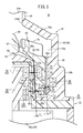
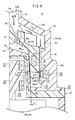
- FIG. 4B is a sectional view taken along line IVB-IVB of FIG. 3 showing the first and second repulsion mechanisms. It is a side sectional view which shows the dynamic pressure bearing of an impeller and a housing in an enlarged manner.
- FIG. 7A is a schematic explanatory view of the pump device according to the first modification.
- FIG. 7B is a schematic explanatory view of the pump device according to the second modification.
- FIG. 7C is a schematic explanatory view of the pump device according to the third modification.
- the pump device 10 is an artificial heart-lung machine device 12 that assists (or substitutes for) the cardiopulmonary function of a patient, and is a power source for removing blood from the patient and sending blood into the body. Used as a source.
- the pump device 10 is configured as a centrifugal pump having an impeller 14 in the device and flowing a fluid by a centrifugal force accompanying the rotation of the impeller 14.
- the heart-lung machine 12 connects a blood removal tube 16 having a blood removal lumen 16a and a blood feeding tube 18 having a blood feeding lumen 18a to a pump device 10 to form a circulation circuit for circulating blood with a patient. doing.
- the tip opening of the blood removal tube 16 is placed in an appropriate biological organ (for example, the femoral vein), and the tip opening of the blood feeding tube 18 is placed in an appropriate biological organ (for example, the femoral artery). Will be done.
- the pump device 10 sucks the patient's blood through the blood removal lumen 16a and sends the blood to the patient through the blood feeding lumen 18a.
- the artificial heart-lung machine 12 may have a configuration in which a reservoir, an artificial lung, or the like (both not shown) are connected in the middle of a circulation circuit (blood removal tube 16 or blood feeding tube 18) in addition to the pump device 10.
- the pump device 10 includes a pump body 20 accommodating the impeller 14, a drive device 22 for rotating the impeller 14, and a control unit 24 (Controller) for controlling the drive of the drive device 22.
- the housing 26 of the pump device 10 is made of a resin material and can be divided into a main body side housing 28 which constitutes the outer shape of the pump main body 20 and a drive side housing 30 which constitutes the outer shape of the drive device 22.
- the main body side housing 28 and the drive side housing 30 are detachably configured and can be assembled to each other at the time of use, so that the driving force of the driving device 22 can be transmitted to the impeller 14 of the pump main body 20.
- the pump body 20 is removed from the drive device 22 and discarded. That is, the pump body 20 is configured as a disposable type that is replaced after each use and is disposable or sterilized.
- the drive device 22 is configured as a reuse type, and at the next use opportunity, a new pump body 20 is attached to operate the impeller 14 of the pump body 20.
- the main body side housing 28 of the pump main body 20 has an internal space 32 in which the impeller 14 is rotatably accommodated and blood flows in and out.
- the main body side housing 28 has a fixed side box portion 29a formed in a substantially conical shape on the upper side and a disk shape on the lower side, and a fixed side tubular portion 29b formed in a substantially cylindrical shape connected to the fixed side box portion 29a in the lower part. It is composed of a housing unit).
- a blood inflow port 34 connected to the blood removal tube 16 is provided at the ceiling and center of the fixed side box portion 29a. Inside the blood inflow port 34, an inflow path 34a communicating with the internal space 32 is provided. The inflow path 34a communicates with the opening 34a1 provided at the protruding end of the blood inflow port 34 and also communicates with the inflow port 34a2 provided at the boundary with the internal space 32.
- a blood outflow port 36 connected to the blood feeding tube 18 is provided on the outer periphery of the fixed side box portion 29a.
- the blood outflow port 36 projects tangentially from the outer circumference of the fixed side box portion 29a.
- an outflow passage 36a communicating with the internal space 32 is provided inside the blood outflow port 36.
- the outflow passage 36a communicates with the opening 36a1 (see FIG. 1) provided at the protruding end of the blood outflow port 36, and also communicates with the outflow port 36a2 provided at the boundary with the internal space 32.
- the internal space 32 is formed in a shape corresponding to the outer shape of the main body side housing 28 (fixed side box portion 29a, fixed side tubular portion 29b).
- the upper side of the internal space 32 (hereinafter referred to as the upper space 32a) is formed by the inner surface of the fixed side box portion 29a, and the fin portion 60 of the impeller 14 is arranged.
- the lower central portion of the upper space 32a is composed of a shaft-shaped portion 38 of the main body side housing 28 protruding toward the inflow port 34a2 of the blood inflow port 34.
- the fixed-side tubular portion 29b of the main body-side housing 28 has a cylindrical outer peripheral wall 40, a bottom wall 42 forming a lower end portion of the main body-side housing 28, and the above-mentioned axial-shaped portion 38 provided inside the outer peripheral wall 40. And include.
- the lower side of the internal space 32 (hereinafter referred to as the lower space 32b) is formed in a cylindrical shape by the inner surface of the fixed side tubular portion 29b, and rotatably accommodates the driven rotating structure portion 62 of the impeller 14 described later.
- first repulsive magnet 44 is provided near the lower part of the outer peripheral wall 40.
- the first repulsive magnet 44 forms a first repulsive mechanism 86 that repels each other with the impeller-side repulsive magnet 76 provided on the impeller 14.
- the first repulsion mechanism 86 will be described later.
- the shaft-shaped portion 38 provided inside the fixed-side tubular portion 29b has a cylindrical inner peripheral wall 48 and a chevron portion 50 connected to the upper end portion of the inner peripheral wall 48, and the inner peripheral wall 48 and the chevron portion 50.
- An insertion hole 52 is formed inside. That is, the lower space 32b orbits the side of the insertion hole 52. The lower end side of the insertion hole 52 is opened, and the drive side housing 30 is inserted when the pump body 20 and the drive device 22 are assembled.
- the chevron portion 50 of the shaft-shaped portion 38 is formed in a conical shape, and a bearing portion 54 that rotatably supports the impeller 14 is provided at the top thereof.
- the bearing portion 54 is formed in a hemispherical shape and supports the lower side of the rotating shaft body 68 provided in the center of the impeller 14. When the line passing through the hemispherical center and the apex is extended, the bearing portion 54 overlaps the center of the inflow port 34a2 of the blood inflow port 34, and this center is the main body side housing 28 (shaft-shaped portion 38, outer peripheral wall 40). It also coincides with the axis St of.
- the impeller 14 is formed in a cylindrical shape and is accommodated in both the upper space 32a and the lower space 32b in the main body side housing 28.
- the impeller 14 has a fin portion 60 at the upper part and a driven rotating structure portion 62 at the lower part. Inside the fin portion 60 and the driven rotating structure portion 62, a space portion 64 in which the shaft-shaped portion 38 is arranged is formed.
- the fin portion 60 generates a centrifugal force in the blood in the upper space 32a when the impeller 14 rotates.
- the fin portion 60 includes a conical wall portion 66 connected to the upper end of the driven rotating structure portion 62, a rotating shaft body 68 pivotally supported by the bearing portion 54 at the center of the conical wall portion 66, and an upward direction from the upper surface of the conical wall portion 66. It is provided with a plurality of protruding wall portions 70 that project to the surface.
- the space surrounded by the conical wall portion 66 and the pair of protruding wall portions 70 is a flow passage 60a in which the upper portion is open and blood flows.
- the shape of the fin portion 60 is not limited to this, and for example, a shroud (not shown) may be provided on the upper portion of the protruding wall portion 70 to cover the flow passage 60a.
- the conical wall portion 66 is steeper than the chevron portion 50 of the main body side housing 28, and its upper surface is curved in an arch shape. Therefore, a gap (hereinafter referred to as an upper gap 66a) is formed between the chevron portion 50 and the conical wall portion 66.
- the conical wall portion 66 around the rotating shaft body 68 is provided with a plurality of (three) washout holes 67 penetrating the conical wall portion 66.
- the washout hole 67 is formed as an elongated hole long in the circumferential direction, and allows blood to flow through the upper space 32a above the conical wall portion 66 and the upper gap 66a.
- the rotating shaft body 68 is formed in a conical shape that smoothly connects to the conical wall portion 66 and is steeply inclined upward from the protruding wall portion 70.
- the outer periphery of the lower side of the rotating shaft body 68 projects downward and inward in an arc shape, and a concave receiving portion 69 recessed upward is provided in the lower central portion of the rotating shaft body 68.
- the concave receiving portion 69 is formed on an arc concave surface having a curvature smaller than that of the hemispherical bearing portion 54, and comes into contact with the bearing portion 54 when the impeller 14 is not rotating.
- the lower end surface of the movable side tubular portion 72 is separated from the bottom wall 42 of the main body side housing 28 even when the concave receiving portion 69 and the bearing portion 54 are in contact with each other. Further, the concave receiving portion 69 rises from the bearing portion 54 as the impeller 14 rotates.
- the bearing structure of the impeller 14 and the main body side housing 28 is not limited to the above configuration, and various configurations may be adopted.
- the bearing structure may have a configuration in which a pin (not shown) is provided in the center of the main body side housing 28, while a hole (not shown) into which the pin is inserted is provided in the impeller 14.
- the plurality of protruding wall portions 70 of the fin portion 60 extend from the position near the outside of the washout hole 67 to the vicinity of the outer edge of the conical wall portion 66.
- Each protruding wall portion 70 is slightly curved and extends in a plan view. As a result, each protruding wall portion 70 smoothly flows the blood that has entered the flow passage 60a radially outward when the impeller 14 rotates.
- the driven rotating structure portion 62 of the impeller 14 is connected to the conical wall portion 66 of the fin portion 60, and has a cylindrical movable side cylinder portion 72 having a predetermined thickness in the radial direction of the impeller 14.
- the diameter of the movable side cylinder portion 72 is set, for example, in the range of 20 mm to 50 mm. In this embodiment, an impeller 14 having a diameter of 30 mm is applied.
- the movable side cylinder portion 72 has a side peripheral surface (inner peripheral surface 72a, outer peripheral surface 72b) extending parallel to the axial center Si of the impeller 14.
- a driven magnet 74 and an impeller side repulsive magnet 76 are installed inside the movable side cylinder portion 72.
- the driven magnet 74 is arranged at the same height as the driving magnet 92 of the driving device 22 with the pump body 20 and the driving device 22 mounted, and forms a magnetic coupling mechanism 84 with the driving magnet 92. More specifically, the driven magnet 74 is fixed on the upper side of the movable side tubular portion 72 toward the inner side in the radial direction (inner peripheral surface 72a). Further, the axial length (thickness) parallel to the axial center of the driven magnet 74 is set to be substantially the same as the axial length of the driving magnet 92.
- the driven magnet 74 is configured as a driven side multi-pole magnetizing ring magnet 75 that orbits with a constant radius R1 with respect to the axial center Si of the impeller 14.
- the driven side multi-pole magnetizing ring magnet 75 is magnetized so that a plurality of N poles and S poles are alternately arranged along the circumferential direction.
- Examples of the material constituting the driven magnet 74 (driven side multi-pole magnetizing ring magnet 75) include hard magnetic materials such as alnico, ferrite, and neodymium.
- the number of polarities of the driven side multi-pole magnetizing ring magnet 75 is 6 (that is, 3 counter-poles) in FIG. 4A, but is not limited to this.
- the driven magnet 74 is not limited to being configured as a multi-pole magnetizing ring, and is formed in a ring shape by arranging a plurality of arc-shaped magnets having counter poles (N pole, S pole) in the circumferential direction. You may be.
- the impeller-side repulsive magnet 76 is fixed to the lower side of the driven rotating structure portion 62 slightly toward the outer side (outer peripheral surface 72b) in the radial direction. That is, the radius R2 of the impeller side repulsive magnet 76 is longer than the radius R1 of the driven magnet 74. Further, the driven magnet 74 and the impeller side repulsive magnet 76 are largely separated vertically in the driven rotating structure portion 62 so as to suppress the influence of mutual magnetic fields. A shield portion (not shown) that limits the influence of mutual magnetic fields may be provided between the driven magnet 74 and the impeller side repulsive magnet 76.
- the impeller side repulsive magnet 76 is configured as an impeller side inner and outer peripheral unipolar magnetizing ring magnet 77 that orbits with a constant radius R2 from the axis Si of the impeller 14.
- the inner outer peripheral single-pole magnetizing ring magnet 77 on the impeller side has a first polarity (S pole in FIG. 3) over the entire circumference of the outer peripheral portion, and has a second polarity opposite to the first polarity over the entire circumference of the inner peripheral portion. It is magnetized so as to have (N pole in FIG. 3).
- the material constituting the impeller-side repulsive magnet 76 is not particularly limited, and the material mentioned in the driven magnet 74 can be applied.
- the first repulsive magnet 44 is installed on the outer peripheral wall 40 of the fixed side tubular portion 29b facing the driven rotating structure portion 62 of the impeller 14.
- the first repulsive magnet 44 is arranged radially outside and slightly above the impeller side repulsive magnet 76 (position offset in the direction approaching the inflow port 34a2).
- the lower end of the first repulsive magnet 44 is located above the upper end of the impeller side repulsive magnet 76.
- the first repulsive magnet 44 is configured as an outer inner and outer peripheral unipolar magnetizing ring magnet 45 that orbits a position farthest from the axial center St of the main body side housing 28 with a constant radius R3.
- the outer inner and outer peripheral unipolar magnetizing ring magnet 45 has a first polarity (N pole in FIG. 3) over the entire circumference of the outer peripheral portion, and has a second polarity (opposite to the first polarity) over the entire circumference of the inner peripheral portion. In FIG. 3, it is magnetized so as to have an S pole).
- the material constituting the first repulsive magnet 44 is not particularly limited, and the material mentioned in the driven magnet 74 can be applied.
- the impeller-side repulsive magnet 76 and the first repulsive magnet 44 formed on the inflow port 34a2 side of the impeller-side repulsive magnet 76 are the impeller-side repulsive magnet 76 radially inward and downward with respect to the first repulsive magnet 44.
- the repulsive force of the first repulsive mechanism 86 is set to be larger than the attractive force of the magnetic coupling mechanism 84 when the axial center Si of the impeller 14 matches the axial center St of the main body side housing 28.
- the inner peripheral surface 72a of the movable side tubular portion 72 of the impeller 14 and the facing surface 48a of the inner peripheral wall 48 of the housing 26 (main body side housing 28) are dynamically pressured based on the rotation of the impeller 14.
- the bearing 78 is formed.
- the dynamic pressure bearing 78 is a journal bearing that makes the movable side cylinder portion 72 non-contact from the inner peripheral wall 48 by the blood flowing between the facing surface 48a and the inner peripheral surface 72a during the rotation of the impeller 14.
- the dynamic pressure gap (first gap 80 between the facing surface 48a and the inner peripheral surface 72a) of the dynamic pressure bearing 78 is the outer peripheral surface 72b (side circumference) of the movable side cylinder portion 72. It is set sufficiently smaller than the second gap 82 between the surface) and the facing surface 40a of the main body side housing 28 (outer peripheral wall 40).
- the interval I1 of the first gap 80 when the impeller 14 is not rotated is set in the range of 50 ⁇ m to 200 ⁇ m when the fluid is blood, for example, although it depends on the viscosity of the flowing fluid.
- the distance I2 of the second gap 82 is set in the range of, for example, 0.8 mm to 1.2 mm.
- the facing surface 48a and the inner peripheral surface 72a (first gap 80) according to the present embodiment are formed so as to be inclined with respect to the axial centers Si and St of the impeller 14 and the axial portion 38. That is, the facing surface 48a and the inner peripheral surface 72a are formed in a tapered shape that is inclined inward in the radial direction toward the inflow port 34a2, and extend in parallel with each other.
- the facing surface 48a and the inner peripheral surface 72a formed in a tapered shape in this way increase the distance I1 of the first gap 80 by ascending the impeller 14 with the dynamic pressure of the impeller 14 during high-speed rotation.
- the facing surface 40a and the outer peripheral surface 72b forming the second gap 82 extend parallel to the axial centers Si and St.
- the inclination angle ⁇ of the facing surface 48a and the inner peripheral surface 72a with respect to the axial center Si and St is set in the range of, for example, about 0.05 ° to 0.1 °, although it depends on the dimensions of the impeller 14 and the housing 26. It is good.
- the inclination angle ⁇ in this way, for example, when the impeller 14 floats 1 mm from the position when the rotation is stopped, the interval I1 of the first gap 80 can be widened by 50 ⁇ m. If the inclination angle ⁇ is smaller than 0.05 °, the distance I1 of the first gap 80 does not change even if the impeller 14 floats.
- the length of the inner peripheral surface 72a and the facing surface 48a facing each other while inclining each other is preferably set in the range of 10 mm to 100 mm. As a result, even if the impeller 14 floats, an appropriate dynamic pressure can be stably obtained.
- the drive device 22 of the pump device 10 includes a drive-side housing 30 and a motor mechanism 90 housed in the drive-side housing 30. Further, the drive device 22 has a drive magnet 92 and a second repulsion magnet 100 provided in the motor mechanism 90 and attracted to and from the impeller 14.
- the drive-side housing 30 has an annular mounting groove 94 on the upper surface for mounting the pump main body 20 (main body-side housing 28). Further, the portion inside the drive-side housing 30 in the radial direction from the mounting groove 94 is a central convex portion 96 inserted into the insertion hole 52 of the main body-side housing 28.
- the main body side housing 28 of the pump main body 20 and the drive side housing 30 of the drive device 22 are engaged by inserting the central convex portion 96 into the insertion hole 52 while inserting the bottom wall 42 into the mounting groove 94. .. Needless to say, the engagement structure between the pump body 20 and the drive device 22 is not particularly limited.
- a motor body 90a of the motor mechanism 90 is provided inside the drive-side housing 30, and the motor body 90a rotates the rotating body 98 at an appropriate rotation speed under the control of the control unit 24.
- the rotating body 98 protrudes from the motor body 90a and is inserted into the protruding space in the central convex portion 96, and the upper portion thereof bulges outward in the radial direction.
- the pump body 20 and the drive device 22 are mounted, the axis Si of the impeller 14 and the axis Ss of the rotating body 98 overlap each other.
- the upper part of the rotating body 98 is cut out in the upper part and the lower part of the outer peripheral surface on the outer side in the radial direction in a side sectional view, and the driving magnet 92 and the second repulsive magnet 100 are held in this part.
- the drive magnet 92 is fixed to the protruding end of the rotating body 98
- the second repulsive magnet 100 is fixed to the lower part of the bulging portion of the rotating body 98.
- the drive magnet 92 and the second repulsion magnet 100 rotate integrally with the rotating body 98.
- the drive magnet 92 is configured as a drive-side multi-pole magnetizing ring magnet 93 that orbits with a radius R4 shorter than the radius R1 of the driven magnet 74 with respect to the axial center Ss of the rotating body 98.
- the drive-side multi-pole magnetizing ring magnet 93 is magnetized so that a plurality of (six) polarities (N-pole and S-pole) are alternately arranged along the circumferential direction. ..
- the drive magnet 92 is arranged to face the driven magnet 74 on the radial inside of the driven magnet 74 with the pump body 20 and the drive device 22 mounted, thereby forming a magnetic coupling mechanism 84 between the driven magnet 92 and the driven magnet 74. To do.
- the material mentioned in the driven magnet 74 can be appropriately selected.
- the drive magnet 92 is not limited to being composed of a multi-pole magnetizing ring magnet, and is formed in a ring shape by arranging a plurality of arc-shaped magnets having counter poles (N pole, S pole) in the circumferential direction. It may have been done.
- the second repulsive magnet 100 forms a second repulsive mechanism 88 that repels each other with the impeller side repulsive magnet 76.
- the second repulsive magnet 100 is composed of an inner inner peripheral unipolar magnetizing ring magnet 101 that orbits the axial center Ss of the rotating body 98 with the same radius R4 as the driving magnet 92.
- the inner and outer peripheral unipolar magnetizing ring magnet 101 has a first polarity (N pole in FIG. 3) over the entire circumference of the outer peripheral portion, and has a second polarity (opposite to the first polarity) over the entire circumference of the inner peripheral portion. In FIG. 3, it is magnetized so as to have an S pole).
- the material constituting the second repulsive magnet 100 is not particularly limited, and the material mentioned in the driven magnet 74 can be applied.
- the first repulsive magnet 44, the impeller side repulsive magnet 76, and the second repulsive magnet 100 are not limited to being configured as a unipolar magnetizing ring, and have an arcuate shape having opposite poles on the inner peripheral portion and the outer peripheral portion.
- a plurality of magnets may be arranged in the circumferential direction to form a ring.
- the second repulsive magnet 100 is arranged slightly below the impeller side repulsive magnet 76 (at a position offset in the direction away from the inflow port 34a2) with the pump body 20 and the drive device 22 mounted. Therefore, the impeller-side repulsive magnet 76 and the second repulsive magnet 100 generate a repulsive force (repulsive force) that pushes out the impeller-side repulsive magnet 76 on the radial side of the second repulsive magnet 100 and on the inflow port 34a2 side.
- the first distance D1 (shortest distance) between the impeller side repulsive magnet 76 and the first repulsive magnet 44 is shorter than the second distance D2 (shortest distance) between the impeller side repulsive magnet 76 and the second repulsive magnet 100.
- the axial length of the second repulsive magnet 100 is formed longer than the axial length of the first repulsive magnet 44, and a large magnetic flux density is generated with the impeller side repulsive magnet 76.
- the second repulsion mechanism 88 configured in this way applies an upward repulsive force to the impeller 14 when the rotation of the impeller 14 is stopped, but the first repulsion mechanism 86 does not cause the impeller 14 to rise significantly from the bearing portion 54. Balanced to.
- control unit 24 of the pump device 10 is composed of a well-known computer having an input / output interface (not shown), a memory, and a processor, and controls the drive of the motor mechanism 90.
- a monitor, a speaker, an operation button, and the like are provided on the outer surface of the control unit 24, and a user such as a doctor or a nurse sets the drive content of the pump device 10 by operating the operation button.
- the control unit 24 controls the power supply of the battery based on the user's setting information, and rotates the rotating body 98 in the range of, for example, 0 to 10000 rpm.
- the pump device 10 is basically configured as described above, and its operation will be described below.
- the heart-lung machine 12 including the pump device 10 is constructed for a patient who assists cardiopulmonary function.
- the user connects the blood removal tube 16 to the blood inflow port 34 of the pump body 20 and the blood supply tube 18 to the blood outflow port 36 of the pump body 20.
- the first repulsive magnet 44 of the pump main body 20 and the impeller side repulsive magnet 76 form a first repulsive mechanism 86 that repels each other. Therefore, in the pump main body 20 alone, the impeller 14 is pressed in the direction away from the inflow port 34a2 of the main body side housing 28, and the rotating shaft body 68 of the impeller 14 is suppressed from being displaced from the bearing portion 54 when being carried.
- the pump device 10 is assembled by attaching the pump body 20 to the drive device 22.
- the driven magnet 74 and the driving magnet 92 adjacent in the radial direction form a magnetic coupling mechanism 84 with different polarities facing each other.
- the magnetic coupling mechanism 84 generates a magnetic coupling force so that the rotational force of the rotating body 98 can be transmitted to the impeller 14.
- the impeller-side repulsive magnet 76 of the impeller 14 and the second repulsive magnet 100 of the drive device 22 form a second repulsive mechanism 88 that repels each other. That is, in the housing 26, the first repulsion mechanism 86 applies an even repulsive force from the outer side of the impeller 14 to the inner side and the entire circumferential direction, and the second repulsion mechanism 88 is lateral to the inner side of the impeller 14. An even repulsive force is applied from the outside to the entire circumferential direction. Therefore, the impeller 14 receives a repulsive force from the inside and outside of the entire circumferential direction, and the posture is corrected so that the axis Si of the impeller 14 coincides with the axis St of the main body side housing 28.
- the second repulsive magnet 100 pushes out the impeller side repulsive magnet 76 so as to be outward and upward (direction approaching the inflow port 34a2). Therefore, the concave receiving portion 69 of the impeller 14 is likely to be lifted from the bearing portion 54.
- the impeller 14 is in contact with the bearing portion 54 in the mounted state and when the rotation is stopped, but the impeller 14 is not limited to this, and the second repulsion is made so that the impeller 14 floats slightly from the bearing portion 54 when the rotation is stopped.
- the repulsive force of the mechanism 88 may be set.
- the blood flowing into the internal space 32 from the inflow path 34a wraps around from the radial outside of the upper space 32a to the lower space 32b.
- the diameter is on the lower end side of the lower space 32b (between the lower end surface of the movable side cylinder portion 72 and the bottom wall 42). Head inward.
- the blood flows upward through the first gap 80 between the axial portion 38 and the driven rotating structure portion 62, reaches the upper gap 66a, and returns to the upper space 32a via the washout hole 67.
- the dynamic pressure bearing 78 When the impeller 14 rotates, the dynamic pressure bearing 78 is formed by the blood flowing in the first gap 80.
- the dynamic pressure bearing 78 maintains the non-contact property of the impeller 14 with respect to the shaft-shaped portion 38 by generating dynamic pressure in the radial direction, and the axial center Si of the impeller 14 is set to the axial center St of the main body side housing 28. Match.
- the pressure on the outlet 36a2 side of the internal space 32 decreases as the blood flows out from the outflow passage 36a.
- the posture of the axis Si of the impeller 14 is aligned with the axis St by the first and second repulsion mechanisms 86 and 88 and the dynamic pressure bearing 78, so that the vicinity of the outflow port 36a2 is located. It is possible to suppress the lowering posture change and allow blood to flow well.
- the impeller 14 may rise more than necessary by receiving the repulsive force of the first repulsion mechanism 86 (first repulsion magnet 44). Be restricted.
- the impeller 14 rotates at high speed (for example, rotation of 3000 rpm or more), the impeller 14 floats toward the inflow port 34a2, so that the distance I1 between the first gap 80 between the facing surface 48a and the inner peripheral surface 72a expands and the distance I1' It becomes. Therefore, the shearing force generated in the first gap 80 due to the high-speed rotation of the impeller 14 can be suppressed. Therefore, it is possible to significantly reduce hemolysis that is likely to occur due to shearing force.
- the present invention is not limited to the above embodiment, and various modifications can be made according to the gist of the invention.
- the facing surface 48a of the housing 26 and the inner peripheral surface 72a of the impeller 14 are tilted at the same inclination angle ⁇ so that they are parallel to each other, and the first gap 80 is set to a constant interval.
- the facing surface 48a forming the dynamic pressure bearing 78 and the inner peripheral surface 72a may be set to different inclination angles ⁇ (that is, the facing surface 48a and the inner peripheral surface 72a are not parallel to each other). May be good).
- the inclination angle ⁇ of the facing surface 48a with respect to the axial center Si is set to be larger than the inclination angle ⁇ of the inner peripheral surface 72a, so that the distance I1 of the first gap 80 is further widened when the impeller 14 is ascended. Can be done.
- the pump device 10 may be configured not to include one or both of the first and second repulsion mechanisms 86 and 88.
- the pump device 10 may be configured not to include one or both of the first and second repulsion mechanisms 86 and 88.
- the installation positions of the first repulsive magnet 44 and the second repulsive magnet 100 are not particularly limited.
- the first repulsive magnet 44 may be provided not only in the pump main body 20 (main body side housing 28) but also in the drive device 22 (drive side housing 30).
- the second repulsive magnet 100 may be provided not only in the drive device 22 (rotating body 98) but also in the pump main body 20 (main body side housing 28).
- the inner peripheral surface 72a of the movable side tubular portion 72 of the impeller 14 is inclined with respect to the axial center Si, while the fixed side tubular portion 29b of the housing 26.
- the facing surface 48a of the above is parallel to the axis Si.
- the facing surface 48a of the fixed side tubular portion 29b of the housing 26 is inclined with respect to the axial center Si, while the movable side tubular portion 72 of the impeller 14
- the inner peripheral surface 72a is parallel to the axial center Si.
- the facing surface 40a of the outer peripheral wall 40 of the housing 26 (fixed side cylinder portion 29b) and the outer peripheral surface 72b of the movable side cylinder portion 72 of the impeller 14 ( The dynamic pressure bearing 79 is formed in the second gap 82 between the side peripheral surface).
- the facing surface 40a and the outer peripheral surface 72b are formed in a tapered shape inclined with respect to the axial center Si. Specifically, the facing surface 40a and the outer peripheral surface 72b are inclined so as to spread outward in the radial direction toward the inflow port 34a2.
- the dynamic pressure bearing 79 is formed on the radial outer side of the impeller 14, and the dynamic pressure bearing 79 is inclined so that the distance I2 of the dynamic pressure gap (second gap 82) when the impeller 14 floats. Can be expanded. Therefore, the same effect as that of the pump device 10 can be obtained.
- the dynamic pressure bearing 79 formed on the outer side of the impeller 14 in the radial direction may also have a configuration in which only one of the facing surface 40a and the outer peripheral surface 72b is inclined as in the first and second modifications.
- One aspect of the present invention is a pump device 10, 10A to 10C including an impeller 14 and a housing 26 for rotatably accommodating the impeller 14, wherein the impeller 14 is on the opposite side of the fin portion 60 and the fin portion 60.
- the housing 26 includes a housing portion (fixed side cylinder portion 29b) for accommodating the movable side cylinder portion 72, and the housing 26 has a side peripheral surface (inner peripheral surface 72a) of the movable side cylinder portion 72.
- a dynamic pressure gap (first gap 80, first gap 80, first gap 80, 2 Gap 82) is formed, and at least one of the side peripheral surfaces and the facing surfaces 40a and 48a is inclined with respect to the axial center Si of the impeller 14, so that the impeller 14 is rotated as the impeller 14 rotates.
- the dynamic pressure gap widens when ascending.
- the impeller 14 has a dynamic pressure gap (first gap 80, second gap 82) between the side peripheral surfaces (inner peripheral surface 72a, outer peripheral surface 72b) and the facing surfaces 40a and 48a.
- the impeller 14 can be stably rotated by the dynamic pressure during rotation.
- the dynamic pressure gap is widened when the impeller 14 floats due to the dynamic pressure, and the dynamic pressure is increased.
- the shearing force of the gap can be suppressed.
- the pump devices 10, 10A to 10C can satisfactorily flow the fluid, and for example, when the fluid flowing in the housing 26 is blood, it is possible to significantly reduce the occurrence of hemolysis due to shearing force. Become.
- the side peripheral surfaces (inner peripheral surface 72a, outer peripheral surface 72b) and the facing surfaces 40a and 48a are inclined in parallel with each other.
- the pump devices 10 and 10C can have a constant interval while inclining the dynamic pressure gaps (first gap 80, second gap 82) along the axial direction of the impeller 14. Therefore, the pump devices 10 and 10C can suppress the shearing force while maintaining a good rotational posture by the dynamic pressure even if the impeller 14 floats.
- the dynamic pressure gap (first gap 80) is formed inside the movable side cylinder portion 72.
- the pump devices 10, 10A, and 10B can smoothly guide the fluid flowing on the outside of the movable side cylinder portion 72 to the dynamic pressure gap on the inside, and sufficiently exert the dynamic pressure in the dynamic pressure gap.
- the impeller 14 can be rotated stably.
- the inclined side peripheral surfaces (inner peripheral surface 72a, outer peripheral surface 72b) and the facing surfaces 40a and 48a have an inclination angle ⁇ of the impeller 14 with respect to the axial center Si in the range of 0.05 ° to 0.1 °. It is set.
- the pump devices 10, 10A to 10C can appropriately widen the distance between the dynamic pressure gaps (first gap 80, second gap 82) when the impeller 14 rises with rotation, and the shearing force. Can be effectively suppressed.
- the distance between the dynamic pressure gaps (first gap 80, second gap 82) is set in the range of 50 ⁇ m to 200 ⁇ m.
- the pump devices 10, 10A to 10C can stably support and rotate the impeller 14 by the dynamic pressure bearings 78 and 79 formed between the housing 26 and the impeller 14.
- the housing 26 has a hemispherical bearing portion 54
- the impeller 14 has a concave receiving portion 69 that rises from the bearing portion 54 during rotation while contacting the bearing portion 54 when the rotation is stopped.
- the pump devices 10, 10A to 10C can easily raise the impeller 14 when the impeller 14 rotates, and can suppress the occurrence of hemolysis between the bearing portion 54 and the concave receiving portion 69. ..
- the impeller 14 includes a ring-shaped impeller-side repulsive magnet 76 along the circumferential direction of the movable-side tubular portion 72, and the housing 26 has a fixed-side repulsive magnet (th) that repels each other with the impeller-side repulsive magnet 76. It includes one repulsive magnet 44 and a second repulsive magnet 100).
- the pump devices 10, 10A to 10C repel each other between the impeller side repulsive magnet 76 and the fixed side repulsive magnet, and the impeller 14 can be rotated more stably by the repulsive mechanism and the dynamic pressure gap.
Landscapes
- Health & Medical Sciences (AREA)
- Engineering & Computer Science (AREA)
- Heart & Thoracic Surgery (AREA)
- Mechanical Engineering (AREA)
- Cardiology (AREA)
- Life Sciences & Earth Sciences (AREA)
- General Health & Medical Sciences (AREA)
- Anesthesiology (AREA)
- Biomedical Technology (AREA)
- Hematology (AREA)
- Veterinary Medicine (AREA)
- Animal Behavior & Ethology (AREA)
- Public Health (AREA)
- General Engineering & Computer Science (AREA)
- Physics & Mathematics (AREA)
- Fluid Mechanics (AREA)
- Vascular Medicine (AREA)
- Emergency Medicine (AREA)
- Electromagnetism (AREA)
- Structures Of Non-Positive Displacement Pumps (AREA)
- External Artificial Organs (AREA)
Abstract
La présente invention concerne un dispositif de pompe (10) qui est pourvu : d'une turbine (14) ; et d'un carter (26) qui reçoit en rotation la turbine (14). La turbine (14) est pourvue d'une partie ailette (60) et d'une partie cylindrique côté mobile (72) et le carter (26) est pourvu d'une partie cylindrique côté fixe (29b) qui reçoit la partie cylindrique côté mobile (72). Un premier espace (80) est formé entre la surface circonférentielle interne (72a) de la partie cylindrique côté mobile (72) et la surface en regard (48a) qui fait face à la surface circonférentielle interne (72a). La surface circonférentielle interne (72a) et la surface en regard (48a) s'inclinent par rapport au noyau d'arbre (Si) de la turbine (14) et ainsi, le premier espace (80) s'étend lorsque la turbine (14) flotte en fonction de la rotation de la turbine (14).
Priority Applications (2)
| Application Number | Priority Date | Filing Date | Title |
|---|---|---|---|
| JP2021527364A JP7352630B2 (ja) | 2019-06-19 | 2020-03-13 | ポンプ装置 |
| US17/527,224 US12544555B2 (en) | 2019-06-19 | 2021-11-16 | Pump device for pumping blood |
Applications Claiming Priority (2)
| Application Number | Priority Date | Filing Date | Title |
|---|---|---|---|
| JP2019-113877 | 2019-06-19 | ||
| JP2019113877 | 2019-06-19 |
Related Child Applications (1)
| Application Number | Title | Priority Date | Filing Date |
|---|---|---|---|
| US17/527,224 Continuation US12544555B2 (en) | 2019-06-19 | 2021-11-16 | Pump device for pumping blood |
Publications (1)
| Publication Number | Publication Date |
|---|---|
| WO2020255499A1 true WO2020255499A1 (fr) | 2020-12-24 |
Family
ID=74040021
Family Applications (1)
| Application Number | Title | Priority Date | Filing Date |
|---|---|---|---|
| PCT/JP2020/011198 Ceased WO2020255499A1 (fr) | 2019-06-19 | 2020-03-13 | Dispositif de pompe |
Country Status (3)
| Country | Link |
|---|---|
| US (1) | US12544555B2 (fr) |
| JP (1) | JP7352630B2 (fr) |
| WO (1) | WO2020255499A1 (fr) |
Cited By (1)
| Publication number | Priority date | Publication date | Assignee | Title |
|---|---|---|---|---|
| JPWO2022185961A1 (fr) * | 2021-03-04 | 2022-09-09 |
Families Citing this family (22)
| Publication number | Priority date | Publication date | Assignee | Title |
|---|---|---|---|---|
| DE102018201030B4 (de) | 2018-01-24 | 2025-10-16 | Kardion Gmbh | Magnetkuppelelement mit magnetischer Lagerungsfunktion |
| DE102018207594A1 (de) | 2018-05-16 | 2019-11-21 | Kardion Gmbh | Rotor, Magnetkupplungsvorrichtung, Elektromotor für ein Herzunterstützungssystem, Pumpeneinheit für ein Herzunterstützungssystem sowie Verfahren zum Herstellen eines Rotors |
| DE102018207611A1 (de) | 2018-05-16 | 2019-11-21 | Kardion Gmbh | Rotorlagerungssystem |
| DE102018207575A1 (de) | 2018-05-16 | 2019-11-21 | Kardion Gmbh | Magnetische Stirndreh-Kupplung zur Übertragung von Drehmomenten |
| DE102018208550A1 (de) | 2018-05-30 | 2019-12-05 | Kardion Gmbh | Leitungsvorrichtung zum Leiten eines Blutstroms für ein Herzunterstützungssystem, Herzunterstützungssystem und Verfahren zum Herstellen einer Leitungsvorrichtung |
| DE102018208538A1 (de) | 2018-05-30 | 2019-12-05 | Kardion Gmbh | Intravasale Blutpumpe und Verfahren zur Herstellung von elektrischen Leiterbahnen |
| DE102018208539A1 (de) | 2018-05-30 | 2019-12-05 | Kardion Gmbh | Motorgehäusemodul zum Abdichten eines Motorraums eines Motors eines Herzunterstützungssystems und Herzunterstützungssystem und Verfahren zum Montieren eines Herzunterstützungssystems |
| DE102018208549A1 (de) | 2018-05-30 | 2019-12-05 | Kardion Gmbh | Elektronikmodul für ein Herzunterstützungssystem und Verfahren zum Herstellen eines Elektronikmoduls für ein Herzunterstützungssystem |
| DE102018208541A1 (de) | 2018-05-30 | 2019-12-05 | Kardion Gmbh | Axialpumpe für ein Herzunterstützungssystem und Verfahren zum Herstellen einer Axialpumpe für ein Herzunterstützungssystem |
| DE102018210058A1 (de) | 2018-06-21 | 2019-12-24 | Kardion Gmbh | Statorschaufelvorrichtung zur Strömungsführung eines aus einer Austrittsöffnung eines Herzunterstützungssystems ausströmenden Fluids, Herzunterstützungssystem mit Statorschaufelvorrichtung, Verfahren zum Betreiben einer Statorschaufelvorrichtung und Herstellverfahren |
| DE102018210076A1 (de) | 2018-06-21 | 2019-12-24 | Kardion Gmbh | Verfahren und Vorrichtung zum Erkennen eines Verschleißzustands eines Herzunterstützungssystems, Verfahren und Vorrichtung zum Betreiben eines Herzunterstützungssystems und Herzunterstützungssystem |
| DE102018211297A1 (de) | 2018-07-09 | 2020-01-09 | Kardion Gmbh | Herzunterstützungssystem und Verfahren zur Überwachung der Integrität einer Haltestruktur eines Herzunterstützungssystems |
| DE102018211328A1 (de) | 2018-07-10 | 2020-01-16 | Kardion Gmbh | Laufradgehäuse für ein implantierbares, vaskuläres Unterstützungssystem |
| DE102018211327A1 (de) | 2018-07-10 | 2020-01-16 | Kardion Gmbh | Laufrad für ein implantierbares, vaskuläres Unterstützungssystem |
| DE102018212153A1 (de) | 2018-07-20 | 2020-01-23 | Kardion Gmbh | Zulaufleitung für eine Pumpeneinheit eines Herzunterstützungssystems, Herzunterstützungssystem und Verfahren zum Herstellen einer Zulaufleitung für eine Pumpeneinheit eines Herzunterstützungssystems |
| AU2019320533B2 (en) | 2018-08-07 | 2024-11-21 | Kardion Gmbh | Bearing device for a cardiac support system, and method for flushing an intermediate space in a bearing device for a cardiac support system |
| DE102020102474A1 (de) | 2020-01-31 | 2021-08-05 | Kardion Gmbh | Pumpe zum Fördern eines Fluids und Verfahren zum Herstellen einer Pumpe |
| CA3192451A1 (fr) | 2020-09-14 | 2022-03-17 | Johannes Bette | Pompe de support cardiovasculaire dotee d'un impulseur a zone d'ecoulement variable |
| US11670336B2 (en) * | 2020-10-08 | 2023-06-06 | Seagate Technology Llc | Magnetic bearings for data storage devices |
| JP2023550938A (ja) | 2020-11-20 | 2023-12-06 | カルディオン ゲーエムベーハー | ガイドワイヤ補助具付き機械的循環支持システム |
| CN114668967B (zh) * | 2022-03-14 | 2023-09-12 | 心擎医疗(苏州)股份有限公司 | 高水力学性能的离心式磁悬浮血泵 |
| CN118142076B (zh) * | 2024-03-14 | 2024-10-22 | 山东中医药大学第二附属医院(山东省中西医结合医院) | 一种泵血叶轮及辅助血液循环装置 |
Citations (5)
| Publication number | Priority date | Publication date | Assignee | Title |
|---|---|---|---|---|
| JPH03151979A (ja) * | 1989-10-24 | 1991-06-28 | Minnesota Mining & Mfg Co <3M> | 使い捨て式ポンプ作用ユニット |
| JP2002315824A (ja) * | 2001-04-23 | 2002-10-29 | National Institute Of Advanced Industrial & Technology | 人工心臓用回転ポンプ |
| US20110238172A1 (en) * | 2006-08-06 | 2011-09-29 | Mustafa Akdis | Blood pump |
| JP2013160136A (ja) * | 2012-02-06 | 2013-08-19 | Medtech Heart Inc | 血液ポンプ |
| WO2019044738A1 (fr) * | 2017-08-29 | 2019-03-07 | テルモ株式会社 | Dispositif de pompe |
Family Cites Families (4)
| Publication number | Priority date | Publication date | Assignee | Title |
|---|---|---|---|---|
| US5840070A (en) * | 1996-02-20 | 1998-11-24 | Kriton Medical, Inc. | Sealless rotary blood pump |
| JP4016441B2 (ja) * | 1996-10-02 | 2007-12-05 | 株式会社ジェイ・エム・エス | ターボ式血液ポンプ |
| DE102005039446B4 (de) * | 2005-08-18 | 2009-06-25 | Ilias-Medical Gmbh | Vorrichtung zur An- und Abreicherung von Stoffen in einer Flüssigkeit |
| JP5681403B2 (ja) | 2010-07-12 | 2015-03-11 | ソーラテック コーポレイション | 遠心式ポンプ装置 |
-
2020
- 2020-03-13 WO PCT/JP2020/011198 patent/WO2020255499A1/fr not_active Ceased
- 2020-03-13 JP JP2021527364A patent/JP7352630B2/ja active Active
-
2021
- 2021-11-16 US US17/527,224 patent/US12544555B2/en active Active
Patent Citations (5)
| Publication number | Priority date | Publication date | Assignee | Title |
|---|---|---|---|---|
| JPH03151979A (ja) * | 1989-10-24 | 1991-06-28 | Minnesota Mining & Mfg Co <3M> | 使い捨て式ポンプ作用ユニット |
| JP2002315824A (ja) * | 2001-04-23 | 2002-10-29 | National Institute Of Advanced Industrial & Technology | 人工心臓用回転ポンプ |
| US20110238172A1 (en) * | 2006-08-06 | 2011-09-29 | Mustafa Akdis | Blood pump |
| JP2013160136A (ja) * | 2012-02-06 | 2013-08-19 | Medtech Heart Inc | 血液ポンプ |
| WO2019044738A1 (fr) * | 2017-08-29 | 2019-03-07 | テルモ株式会社 | Dispositif de pompe |
Cited By (2)
| Publication number | Priority date | Publication date | Assignee | Title |
|---|---|---|---|---|
| JPWO2022185961A1 (fr) * | 2021-03-04 | 2022-09-09 | ||
| WO2022185961A1 (fr) * | 2021-03-04 | 2022-09-09 | テルモ株式会社 | Dispositif de pompe |
Also Published As
| Publication number | Publication date |
|---|---|
| JPWO2020255499A1 (fr) | 2020-12-24 |
| US20220072296A1 (en) | 2022-03-10 |
| JP7352630B2 (ja) | 2023-09-28 |
| US12544555B2 (en) | 2026-02-10 |
Similar Documents
| Publication | Publication Date | Title |
|---|---|---|
| WO2020255499A1 (fr) | Dispositif de pompe | |
| US11686318B2 (en) | Centrifugal blood pump device | |
| KR101356414B1 (ko) | 회전 혈액 펌프 | |
| US11801377B2 (en) | Centrifugal blood pump | |
| US5360317A (en) | Centrifugal blood pump | |
| EP0591208B1 (fr) | Pompe a liquide a roue helice soulevee par levitation | |
| US20140179983A1 (en) | Stabilizing drive for contactless rotary blood pump impeller | |
| JP2022545590A (ja) | インターベンション式心室補助装置 | |
| JPWO2015098708A1 (ja) | 遠心ポンプ | |
| JP7422730B2 (ja) | ポンプ装置 | |
| JP2005118237A (ja) | 軸方向または径方向に動圧軸受を有する遠心血液ポンプ | |
| JP7123059B2 (ja) | ポンプ装置 | |
| JP7422729B2 (ja) | ポンプ装置 | |
| JP7764380B2 (ja) | ポンプ装置 | |
| JP7355502B2 (ja) | ポンプ装置 | |
| JP7149875B2 (ja) | ポンプ装置 | |
| EP3854447B1 (fr) | Pompe sanguine centrifuge | |
| JP2605192B2 (ja) | 血液ポンプ | |
| JP2019058442A (ja) | ポンプ装置 | |
| JP2019154574A (ja) | ポンプ装置 | |
| JP2003079720A (ja) | 血液ポンプ | |
| JP2003093500A (ja) | 血液ポンプ | |
| JPH05111535A (ja) | 血液ポンプ | |
| JP2012161525A (ja) | 遠心式血液ポンプおよび遠心式血液ポンプ装置 | |
| JPH05212111A (ja) | 血液ポンプ |
Legal Events
| Date | Code | Title | Description |
|---|---|---|---|
| 121 | Ep: the epo has been informed by wipo that ep was designated in this application |
Ref document number: 20827326 Country of ref document: EP Kind code of ref document: A1 |
|
| ENP | Entry into the national phase |
Ref document number: 2021527364 Country of ref document: JP Kind code of ref document: A |
|
| NENP | Non-entry into the national phase |
Ref country code: DE |
|
| 122 | Ep: pct application non-entry in european phase |
Ref document number: 20827326 Country of ref document: EP Kind code of ref document: A1 |