WO2020255564A1 - Unité de moteur et corps mobile - Google Patents
Unité de moteur et corps mobile Download PDFInfo
- Publication number
- WO2020255564A1 WO2020255564A1 PCT/JP2020/017979 JP2020017979W WO2020255564A1 WO 2020255564 A1 WO2020255564 A1 WO 2020255564A1 JP 2020017979 W JP2020017979 W JP 2020017979W WO 2020255564 A1 WO2020255564 A1 WO 2020255564A1
- Authority
- WO
- WIPO (PCT)
- Prior art keywords
- motor
- connector
- motor unit
- substrate
- case
- Prior art date
- Legal status (The legal status is an assumption and is not a legal conclusion. Google has not performed a legal analysis and makes no representation as to the accuracy of the status listed.)
- Ceased
Links
Images







Classifications
-
- H—ELECTRICITY
- H02—GENERATION; CONVERSION OR DISTRIBUTION OF ELECTRIC POWER
- H02K—DYNAMO-ELECTRIC MACHINES
- H02K5/00—Casings; Enclosures; Supports
- H02K5/04—Casings or enclosures characterised by the shape, form or construction thereof
- H02K5/22—Auxiliary parts of casings not covered by groups H02K5/06-H02K5/20, e.g. shaped to form connection boxes or terminal boxes
- H02K5/225—Terminal boxes or connection arrangements
-
- F—MECHANICAL ENGINEERING; LIGHTING; HEATING; WEAPONS; BLASTING
- F04—POSITIVE - DISPLACEMENT MACHINES FOR LIQUIDS; PUMPS FOR LIQUIDS OR ELASTIC FLUIDS
- F04D—NON-POSITIVE-DISPLACEMENT PUMPS
- F04D25/00—Pumping installations or systems
- F04D25/02—Units comprising pumps and their driving means
- F04D25/06—Units comprising pumps and their driving means the pump being electrically driven
- F04D25/0693—Details or arrangements of the wiring
-
- H—ELECTRICITY
- H02—GENERATION; CONVERSION OR DISTRIBUTION OF ELECTRIC POWER
- H02K—DYNAMO-ELECTRIC MACHINES
- H02K11/00—Structural association of dynamo-electric machines with electric components or with devices for shielding, monitoring or protection
- H02K11/30—Structural association with control circuits or drive circuits
- H02K11/33—Drive circuits, e.g. power electronics
-
- H—ELECTRICITY
- H02—GENERATION; CONVERSION OR DISTRIBUTION OF ELECTRIC POWER
- H02K—DYNAMO-ELECTRIC MACHINES
- H02K15/00—Processes or apparatus specially adapted for manufacturing, assembling, maintaining or repairing of dynamo-electric machines
- H02K15/30—Manufacture of winding connections
- H02K15/32—Manufacture of terminal arrangements; Connecting the terminals to external circuits
-
- H—ELECTRICITY
- H02—GENERATION; CONVERSION OR DISTRIBUTION OF ELECTRIC POWER
- H02K—DYNAMO-ELECTRIC MACHINES
- H02K5/00—Casings; Enclosures; Supports
- H02K5/04—Casings or enclosures characterised by the shape, form or construction thereof
- H02K5/08—Insulating casings
-
- H—ELECTRICITY
- H02—GENERATION; CONVERSION OR DISTRIBUTION OF ELECTRIC POWER
- H02K—DYNAMO-ELECTRIC MACHINES
- H02K7/00—Arrangements for handling mechanical energy structurally associated with dynamo-electric machines, e.g. structural association with mechanical driving motors or auxiliary dynamo-electric machines
- H02K7/14—Structural association with mechanical loads, e.g. with hand-held machine tools or fans
-
- F—MECHANICAL ENGINEERING; LIGHTING; HEATING; WEAPONS; BLASTING
- F05—INDEXING SCHEMES RELATING TO ENGINES OR PUMPS IN VARIOUS SUBCLASSES OF CLASSES F01-F04
- F05D—INDEXING SCHEME FOR ASPECTS RELATING TO NON-POSITIVE-DISPLACEMENT MACHINES OR ENGINES, GAS-TURBINES OR JET-PROPULSION PLANTS
- F05D2260/00—Function
- F05D2260/30—Retaining components in desired mutual position
-
- H—ELECTRICITY
- H01—ELECTRIC ELEMENTS
- H01R—ELECTRICALLY-CONDUCTIVE CONNECTIONS; STRUCTURAL ASSOCIATIONS OF A PLURALITY OF MUTUALLY-INSULATED ELECTRICAL CONNECTING ELEMENTS; COUPLING DEVICES; CURRENT COLLECTORS
- H01R13/00—Details of coupling devices of the kinds covered by groups H01R12/70 or H01R24/00 - H01R33/00
- H01R13/73—Means for mounting coupling parts to apparatus or structures, e.g. to a wall
-
- H—ELECTRICITY
- H01—ELECTRIC ELEMENTS
- H01R—ELECTRICALLY-CONDUCTIVE CONNECTIONS; STRUCTURAL ASSOCIATIONS OF A PLURALITY OF MUTUALLY-INSULATED ELECTRICAL CONNECTING ELEMENTS; COUPLING DEVICES; CURRENT COLLECTORS
- H01R25/00—Coupling parts adapted for simultaneous co-operation with two or more identical counterparts, e.g. for distributing energy to two or more circuits
- H01R25/006—Coupling parts adapted for simultaneous co-operation with two or more identical counterparts, e.g. for distributing energy to two or more circuits the coupling part being secured to apparatus or structure, e.g. duplex wall receptacle
-
- H—ELECTRICITY
- H02—GENERATION; CONVERSION OR DISTRIBUTION OF ELECTRIC POWER
- H02K—DYNAMO-ELECTRIC MACHINES
- H02K2211/00—Specific aspects not provided for in the other groups of this subclass relating to measuring or protective devices or electric components
- H02K2211/03—Machines characterised by circuit boards, e.g. pcb
Definitions
- the present disclosure relates to a motor unit and a moving body, and more particularly to a motor unit including a connector and a moving body including the motor unit.
- Patent Document 1 describes a motor (motor unit) including a connector.
- a part of the housing of the motor is formed by molding a resin material, and a power supply connector for supplying an exciting current is integrally molded in the housing.
- the present disclosure is an invention made in view of the above points.
- An object of the present disclosure is to provide a motor unit and a moving body capable of relieving stress from a connector to a substrate.
- the motor unit includes a motor, a substrate, a motor case, a connector, and a regulation unit.
- a motor including a rotating shaft extending in the axial direction rotates about the axis of the rotating shaft as the center of rotation.
- a circuit element constituting a drive circuit for driving a motor is provided on the substrate.
- the motor case houses the motor and holds the substrate.
- the connector includes a connection terminal that is directly connected to the board.
- the regulating unit regulates the movement of the connector with respect to the substrate by contacting the connector.
- the regulation unit regulates the movement of the connector at least in the axial direction.
- the motor unit may further include a board guide.
- the board guide may support the board.
- the motor case may hold the substrate via the substrate guide.
- the connector may be integrated with the board guide.
- the motor case may include a metal part.
- the motor unit may further include a bottom plate.
- the bottom plate may be attached to the motor case so as to cover the opening of the motor case.
- the regulating part may include a contact part. The contact may come into contact with the bottom plate when a force is applied to the connector in the direction in which the bottom plate is attached.
- the bottom plate and the contact portion are in contact with each other in a state where no external force is applied.
- the regulation part may include a claw part that holds the connector by snap fit.
- the regulating portion may have a fixing portion that is integrally formed with the connector and is screwed to the fan case.
- connection terminal may include an elastic portion having elasticity.
- the motor unit includes a motor, a substrate, a motor case, blades, a fan case, and a connector.
- the rotor including the rotating shaft extending in the axial direction rotates about the axial center of the rotating shaft as the center of rotation.
- a circuit element constituting a drive circuit for driving a motor is provided on the substrate.
- the motor case houses the motor and holds the substrate.
- the blades are rotated by a motor.
- the fan case houses the blades.
- the connector includes a connection terminal that is directly connected to the board.
- the connector further includes a housing for accommodating the connection terminals. The accommodating portion is provided integrally with the fan case.
- the stress from the connector to the substrate can be relaxed.
- FIG. 8 is an external view of the motor unit according to the second embodiment.
- FIG. 9 is an enlarged view of a main part of the same motor unit.
- FIG. 10 is an exploded perspective view of a main part of the motor unit according to the third embodiment.
- FIG. 11 is an exploded perspective view of the motor unit according to the fourth embodiment.
- FIG. 12 is an external view of a main part of the motor unit according to the fifth embodiment.
- FIG. 13 is a schematic view of the vehicle according to the sixth embodiment.
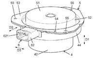
- FIG. 1 is an external view of the motor unit 1 according to the first embodiment.
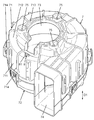
- FIG. 3 is an external view of a main part of the same motor unit 1.
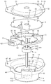
- FIG. 4 is an exploded perspective view of a main part of the same motor unit 1.
- the motor unit 1 according to the first embodiment includes a motor 11 (see FIG. 13), a substrate 2, a substrate guide 3, a motor case 4, and a bottom plate 5.
- a connector 6, a blade 12 (see FIG. 13), a fan case 7, and a regulating unit 8 are provided.
- the motor unit 1 is used for, for example, a moving body.
- Examples of the moving body in which the motor unit 1 is used include vehicles such as a four-wheeled vehicle, a two-wheeled vehicle, and a three-wheeled vehicle.
- the motor 11 is housed in the motor case 4 as shown in FIG.
- the motor 11 has a rotor 111, a stator 112 facing the rotor 111, a rotating shaft 113 extending in the axial direction, and a bearing 114 supporting the rotating shaft 113.
- the rotor 111 has a rotor frame 115 and a rotor magnet 116, and rotates about the axis of the rotation shaft 113 as a rotation center.
- the motor 11 rotates with the first direction D1 as the axial direction.
- the motor 11 is, for example, an inner rotor type motor as shown in FIG.
- the motor 11 is directly or indirectly connected to the blade 12 (see FIG. 13), and the blade 12 rotates in conjunction with the rotation of the motor 11.
- the motor 11 is not limited to the inner rotor type motor, and may be an outer rotor type motor.
- the substrate 2 shown in FIG. 4 is, for example, a printed circuit board.
- the substrate 2 is formed in a substantially circular shape in a plan view.
- the substrate 2 has a through hole 21 in the center through which the rotating shaft 113 is passed.
- the substrate 2 has a plurality of (three in the illustrated example) mounting holes 22.
- the substrate 2 is housed in the motor case 4 while being held by the substrate guide 3.
- the board 2 is provided with a plurality of circuit elements for driving the motor 11.
- a plurality of circuit elements provided on the substrate 2 constitute a drive circuit 13 (see FIG. 13) that drives the motor 11.
- the drive circuit 13 is electrically connected to the motor 11 via an electric path such as a lead wire.
- the drive circuit 13 generates drive power for driving the motor 11 from the power supplied from the control device 92 (see FIG. 13) via the connector 6 and the cable 93 (see FIG. 13).
- the drive circuit 13 supplies the generated drive power to the motor 11.
- the motor 11 is rotationally driven by being supplied with drive power from the drive circuit 13.
- the substrate guide 3 is formed in an annular shape having an opening 31 at the center.
- the substrate 2 is arranged on one surface of the first direction D1.
- the substrate guide 3 holds the substrate 2 between the bottom plate 5 and the substrate guide 3 in the first direction D1.
- a plurality of (three in the illustrated example) protruding portions 32 are formed on the outer peripheral portion of the surface of the substrate guide 3 on the substrate 2 side.
- Each protruding portion 32 is formed in a columnar shape and protrudes in the first direction D1.
- Each protrusion 32 penetrates the circular mounting hole 22 formed in the substrate 2 and is heated.
- the substrate guide 3 has a plurality of (three in the illustrated example) insertion holes 33 formed on the outer peripheral portion of the opening 31. A lead wire connecting the motor 11 and the substrate 2 is passed through each insertion hole 33.
- the motor case 4 is a metal member formed in a bottomed cylindrical shape in which one of the first directions D1 is open, and the motor 11 is housed therein. Contain.
- the motor case 4 holds the substrate 2.
- the motor case 4 holds the substrate 2 via the substrate guide 3.
- the motor case 4 has a bottom surface portion 41, a tubular portion 42, an annular portion 43, a tubular portion 44, and a tip portion 45.
- the bottom surface portion 41, the tubular portion 42, the annular portion 43, the tubular portion 44, and the tip portion 45 are integrally formed.
- the bottom surface portion 41 has, for example, a disk shape.
- the tubular portion 42 is provided so as to project from the outer peripheral edge of the bottom surface portion 41.
- the annular portion 43 is provided at the tip of the tubular portion 42.
- the tubular portion 44 is provided so as to project from the outer peripheral edge of the annular portion 43.
- the tip portion 45 is provided at the tip of the tubular portion 44.
- the tip portion 45 has a plurality of (two in the illustrated example) through holes 46 and a plurality of (three in the illustrated example) through holes 47.
- the bottom plate 5 is a metal member formed in a bottomed cylindrical shape in which one of the first directions D1 is open.
- the bottom plate 5 has a bottom surface portion 51, a tubular portion 52, and a tip portion 53.
- the bottom surface portion 51, the cylinder portion 52, and the tip portion 53 are integrally formed.
- the bottom surface portion 51 has, for example, a disk shape.
- the tubular portion 52 is provided so as to project from the outer peripheral edge of the bottom surface portion 51.
- the tip portion 53 is provided at the tip of the tubular portion 52.
- the tip portion 53 has a plurality of (only one is shown) through holes 54 and a plurality of (three in the illustrated example) through holes 55.
- the bottom plate 5 is attached to the motor case 4 so as to cover the opening of the motor case 4. More specifically, screws are inserted into the plurality of through holes 46 of the motor case 4 and the plurality of through holes 54 of the bottom plate 5, and the motor case 4 and the bottom plate 5 are screw-fixed.
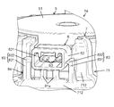
- FIG. 2 is an enlarged view of a main part of the motor unit 1 according to the first embodiment.
- the connector 6 is a connecting member that electrically connects the substrate 2 and the cable 93 (see FIG. 13).
- the connector 6 is a through-hole mounting type connector, and the insertion / removal direction of the connector 6 is along the second direction D2 (radial direction) orthogonal to the first direction D1.
- FIG. 6 is a perspective view showing the attachment of the connector 6 in the motor unit 1 according to the first embodiment.
- the connector 6 includes a connection unit 61 and an accommodating portion 62.
- the plurality of connection terminals 63 are directly connected to the board 2. More specifically, the plurality of connection terminals 63 are electrically connected to the substrate 2 and the cable 93 (see FIG. 13).
- the plurality of connection terminals 63 are made of a metal such as brass.
- the plurality of connection terminals 63 are held by the terminal holding portions 64 so as to line up in the third direction D3.
- the third direction D3 is orthogonal to both the first direction D1 and the second direction D2.
- Each connection terminal 63 has a main body 631, a board connection pin 632, and a cable connection pin 633.
- the main body 631, the board connection pin 632, and the cable connection pin 633 are integrally formed.
- the main body 631 connects the substrate connection pin 632 formed at one end of the second direction D2 and the cable connection pin 633 formed at the other end of the second direction D2. It is formed.
- the main body 631 is formed in a rectangular plate shape, and a part of the main body 631 is sealed in a resin terminal holding portion 64. A plurality of connection terminals 63 are integrally held by the terminal holding portion 64.
- the plurality of substrate connection pins 632 are formed in a prismatic shape along the first direction D1 and penetrate the pin insertion holes 23 formed in the substrate 2.
- Each board connection pin 632 is electrically and mechanically connected to the board 2 by being soldered to the board 2.
- the plurality of board connection pins 632 are formed so as to be lined up along the third direction D3.
- the plurality of substrate connecting pins 632 are formed at substantially equal intervals in the third direction D3.
- the substantially equal spacing referred to here includes not only the case where the spacing between the plurality of substrate connecting pins 632 is completely the same, but also the case where the spacing is deviated within an error range.
- the plurality of cable connection pins 633 are formed so as to be lined up along the third direction D3.
- Each cable connection pin 633 is formed so as to extend from the end of the second direction D2 in the main body portion 631 to the second direction D2, and protrudes from the terminal holding portion 64.
- Each cable connection pin 633 is electrically and mechanically connected to the pin receiving member of the connector of the cable 93 (see FIG. 13).
- the terminal holding portion 64 is a resin molded product made of, for example, PBT (Poly Butene terephthate) or the like.
- the terminal holding unit 64 integrally holds a plurality of connection terminals 63.
- the terminal holding portion 64 holds a plurality of connecting terminals 63 by hoop molding.
- the terminal holding portion 64 is integrally molded with a plurality of connection terminals 63 in a state of being connected to the frame. Then, after molding, each connection terminal 63 is separated from the frame. Further, the connection terminals 63 are separated from each other.
- the terminal holding portion 64 and the plurality of connection terminals 63 are integrally molded by hoop molding.
- connection terminal 63 the manufacturing error of the position of the connection terminal 63 is suppressed as compared with the insert molding in which the plurality of connection terminals 63 are integrally molded with the terminal holding portion 64 in an independent state.
- the plurality of bent portions of the connection terminal 63 are formed by bending after the terminal holding portion 64 is formed.
- the accommodating portion 62 is a resin molded product made of, for example, PBT or the like. In the first embodiment, the accommodating portion 62 is formed integrally with the substrate guide 3.
- the accommodating portion 62 is formed in a square tubular shape having an accommodating hole 621 penetrating in the second direction D2.
- the accommodating portion 62 is formed so as to project in the second direction D2 from the end portion of the substrate guide 3.
- the accommodating hole 621 has a rectangular cross section orthogonal to the second direction D2.
- the connection unit 61 is inserted into the accommodating hole 621 from one side (board guide 3 side) of the second direction D2, and the connector of the cable 93 (see FIG. 13) is inserted from the other side of the second direction D2.
- the plurality of connection terminals 63 of the connection unit 61 and the cable 93 are electrically connected.
- connection unit 61 having the connection terminal 63 is formed separately from the accommodating portion 62 that holds the substrate 2.
- workability when assembling the connection terminal 63 into the connector 6 is improved as compared with the case where the connection unit and the accommodating portion are integrally formed, and the position of the connection terminal 63 at the time of manufacturing the connection unit 61 is improved. Manufacturing error can be suppressed.
- the blades 12 are rotated by a motor 11 (see FIG. 13). More specifically, the blade 12 is housed in the fan case 7 in a state of being directly or indirectly connected to the motor 11. For example, the blade 12 is attached to a portion of the rotating shaft 113 that protrudes from the motor case 4. In the fan case 7, the blades 12 rotate in conjunction with the rotation of the motor 11. Thereby, the cooling effect can be enhanced.
- the fan case 7 shown in FIG. 1 houses the blades 12 (see FIG. 13).
- the fan case 7 further accommodates the motor case 4, the bottom plate 5, and the connector 6.
- the fan case 7 is made of resin or the like.
- FIG. 7 is an external view of the fan case 7 of the motor unit 1 according to the first embodiment.
- the fan case 7 has a first member 71 and a second member 72.
- the first member 71 includes a base portion 711, an annular portion 712, a protruding portion 713, and a plurality of protruding portions 714.
- the base 711 has a tubular shape.
- the annular portion 712 projects inward from one end (upper end of FIG. 7) of the base portion 711.
- the protruding portion 713 projects from the inner peripheral end of the annular portion 712 in the first direction D1.
- the plurality of protrusions 714 are provided at the other end of the base portion 711 (the lower end of FIG. 7).
- the plurality of protrusions 714 are provided around the other end side of the base portion 711 at a certain distance from each other.
- the fan case 7 has an exhaust port 74 for exhaust.
- the exhaust port 74 has an opening surface whose normal is the direction orthogonal to the first direction D1.
- the fan case 7 has a plurality of (three in the illustrated example) through holes 75.
- the plurality of through holes 75 are formed in the first member 71.
- the motor case 4 and the bottom plate 5 fixed, the motor case 4 has a plurality of through holes 47 (see FIG. 4), the bottom plate 5 has a plurality of through holes 55 (see FIG. 4), and the fan case 7.
- the motor case 4 and the bottom plate 5 are attached to the fan case 7 by inserting the screws 14 (see FIG. 1) into the plurality of through holes 75.
- Regulation unit 8 The regulation unit 8 shown in FIG. 2 regulates the movement of the connector 6 with respect to the substrate 2 by coming into contact with the connector 6.
- the regulation unit 8 includes the protrusion 81 as shown in FIG.
- the protruding portion 81 is made of resin or the like, protrudes from a part of the fan case 7, and faces the connector 6. More specifically, the protruding portion 81 protrudes from a part of the annular portion 712 of the fan case 7 along the first direction D1 and faces the connector 6 through the gap in the first direction D1.
- the protrusion 81 is made of, for example, a resin.
- the protruding portion 81 is formed integrally with the fan case 7. When a force in the direction approaching the protrusion 81 (downward in FIG. 2) is applied to the connector 6 in the first direction D1, the connector 6 comes into contact with the protrusion 81. When the connector 6 comes into contact with the protruding portion 81, the connector 6 cannot move further downward. As a result, the downward movement of the connector 6 can be restricted.
- FIG. 5A is a cross-sectional view of a main part of the motor unit according to the first embodiment in a normal state.
- FIG. 5B is a cross-sectional view of a main part of the motor unit of the same as above in a state where a force is applied.
- the regulating unit 8 includes a contact unit 82.
- the contact portion 82 is made of resin or the like.
- the contact portion 82 is provided in the accommodating portion 62 of the connector 6.
- the contact portion 82 has a predetermined gap ⁇ 1 with the bottom plate 5.
- the contact portion 82 is thicker in the radial direction than the periphery.
- the protrusion 81 and the contact 82 regulate the movement of the connector 6 in at least the first direction D1.
- a force is applied to the connector 6 along the opening side of the first direction D1 (upward in FIG. 5B), that is, in the axial direction in which the bottom plate 5 is attached.
- the contact portion 82 comes into contact with the bottom plate 5.
- the regulating portion 8 restricts the movement of the connector 6 in the first direction D1.
- the protruding portion 81 and the contact portion 82 restrict movement in opposite directions with respect to the connector 6.
- the contact portion 82 may be in contact with the bottom plate 5 in the axial direction in which the bottom plate 5 is attached and in a normal state in which no force is applied to the connector 6.
- the regulation unit 8 comes into contact with the connector 6 to restrict the movement of the connector 6 with respect to the substrate 2.
- the deformation of the connector 6 can be reduced, so that the stress from the connector 6 to the substrate 2 can be relaxed.
- the movement of the connector 6 in the axial direction (first direction D1) of the motor 11 is regulated.
- the deformation of the connector 6 in the first direction D1 can be reduced, so that the stress from the connector 6 to the substrate 2 can be further relaxed.
- the insertion / removal direction of the connector 6 is along the radial direction (second direction D2). As a result, the stress from the connector 6 to the substrate 2 can be further relaxed.
- the motor unit 1 according to the first embodiment is provided with a protruding portion 81 that protrudes from a part of the fan case 7 and faces the connector 6.
- the regulating portion 8 can be integrally formed with the fan case 7.
- the motor case 4 holds the substrate 2 via the substrate guide 3. As a result, the substrate 2 can be stably held.
- the connector 6 is provided with a connection terminal 63 including an elastic portion having elasticity. As a result, when a force is applied to the connector 6, the force can be relaxed at the connection terminal 63.
- the motor unit 1 includes a through-hole mounting type connector 6. As a result, the connector 6 can be easily connected to the substrate 2 as compared with the surface mount connector.
- the motor case 4 is made of metal, but the motor case 4 is not limited to all metal parts. As a modification of the first embodiment, only a part of the motor case 4 may be a metal part. In short, the motor case 4 preferably includes a metal portion.
- the motor case 4 includes a resin member and a metal member.
- the motor case 4 holds the substrate 2 with a resin member.
- the resin member holds the substrate 2 directly or via the substrate guide 3.
- the metal member is provided around the resin member.
- the motor unit 1 according to the above modification also has the same effect as the motor unit 1 according to the first embodiment.
- FIG. 8 is an external view of the motor unit 1a according to the second embodiment.
- FIG. 9 is an enlarged view of a main part of the motor unit 1a of the above.
- the motor unit 1a according to the second embodiment is different from the motor unit 1 according to the first embodiment (see FIG. 1) in that it has a snap-fit structure.
- the same components as those of the motor unit 1 according to the first embodiment are designated by the same reference numerals and the description thereof will be omitted.
- the motor unit 1a has a motor 11 (see FIG. 4), a substrate 2, a substrate guide 3, a motor case 4, a bottom plate 5, and a connector, similarly to the motor unit 1 according to the first embodiment.
- a vane 12 (see FIG. 13), and a fan case 7 are provided.
- the motor unit 1a includes a regulation unit 8a as shown in FIGS. 8 and 9 in place of the regulation unit 8 of the first embodiment.
- the motor unit 1a is used for a moving body such as a vehicle, like the motor unit 1 according to the first embodiment.
- the regulating portion 8a includes a plurality of (two in the illustrated example) protruding portions 81a and a plurality of (two in the illustrated example) claw portions 83.
- the regulation unit 8a of the second embodiment the same configuration and function as the regulation unit 8 of the first embodiment (see FIG. 2) will not be described.
- the plurality of protrusions 81a are provided side by side along the third direction D3.
- Each protruding portion 81a has a rectangular plate shape, projects from a part of the fan case 7, and faces the connector 6. More specifically, each protruding portion 81a protrudes from a part of the annular portion 712 of the fan case 7 along the first direction D1.
- Each protrusion 81a faces the connector 6 via a gap in the first direction D1.
- Each protrusion 81a is made of, for example, a resin.
- Each protrusion 81a is integrally formed with the fan case 7.
- Each protrusion 81a is made of the same material as the fan case 7.
- the plurality of claws 83 hold the connector 6 with a snap fit.
- Each claw portion 83 projects from a part of the fan case 7 and is located on both sides of the connector 6 in the third direction D3. More specifically, each claw portion 83 projects from a part of the annular portion 712 of the fan case 7 along the first direction D1.
- Each claw portion 83 is made of, for example, a resin.
- Each claw portion 83 is formed integrally with the fan case 7.
- Each claw portion 83 is made of the same material as the fan case 7.
- Each claw portion 83 has a base portion 831 and a tip portion 832.
- the base portion 831 and the tip portion 832 are integrally formed.
- the base 831 has a rectangular plate shape. One end of the base 831 in the longitudinal direction is connected to the annular portion 712 of the fan case 7.
- the tip portion 832 is provided so as to project from the other end of the base portion 831 toward the connector 6.
- a claw portion 83 for holding the connector 6 is provided.
- the connector 6 can be fixed by a snap fit. Therefore, the movement of the connector 6 can be easily regulated.
- FIG. 10 is an exploded perspective view of a main part of the motor unit 1b according to the third embodiment.
- the motor unit 1b according to the third embodiment is different from the motor unit 1 according to the first embodiment (see FIG. 1) in that the connector 6b is divided and formed as shown in FIG.
- the same components as those of the motor unit 1 according to the first embodiment are designated by the same reference numerals and the description thereof will be omitted.
- the motor unit 1b includes a motor 11, a substrate 2, a substrate guide 3, a motor case 4, a bottom plate 5, and blades 12 (see FIG. 13), similarly to the motor unit 1 according to the first embodiment. ), A fan case 7, and a regulation unit 8 (see FIG. 2). Further, the motor unit 1b includes a connector 6b as shown in FIG. 10 instead of the connector 6 of the first embodiment (see FIG. 2).
- the motor unit 1b is used for a moving body such as a vehicle, like the motor unit 1 according to the first embodiment.
- the connector 6b includes a connection unit 61b and an accommodating portion 62b.
- the same configuration and function as the connector 6 of the first embodiment (see FIG. 2) will not be described.
- the connection unit 61b includes a plurality of (four in the illustrated example) connection terminals 63b and a terminal holding portion 64b.
- the plurality of connection terminals 63b are connected to the substrate 2.
- the terminal holding portion 64b is made of, for example, resin, and is attached to the substrate 2 in a state where a plurality of connecting terminals 63b are lined up along the third direction D3.
Landscapes
- Engineering & Computer Science (AREA)
- Power Engineering (AREA)
- Microelectronics & Electronic Packaging (AREA)
- Mechanical Engineering (AREA)
- General Engineering & Computer Science (AREA)
- Manufacturing & Machinery (AREA)
- Motor Or Generator Frames (AREA)
- Connection Of Motors, Electrical Generators, Mechanical Devices, And The Like (AREA)
- Structures Of Non-Positive Displacement Pumps (AREA)
Abstract
Priority Applications (4)
| Application Number | Priority Date | Filing Date | Title |
|---|---|---|---|
| EP20827561.0A EP3989413A4 (fr) | 2019-06-20 | 2020-04-27 | Unité de moteur et corps mobile |
| CN202080042392.1A CN113939981B (zh) | 2019-06-20 | 2020-04-27 | 电动机单元和移动体 |
| JP2021527424A JP7457892B2 (ja) | 2019-06-20 | 2020-04-27 | モータユニット及び移動体 |
| US17/617,273 US11990820B2 (en) | 2019-06-20 | 2020-04-27 | Motor unit and moving body |
Applications Claiming Priority (2)
| Application Number | Priority Date | Filing Date | Title |
|---|---|---|---|
| JP2019115002 | 2019-06-20 | ||
| JP2019-115002 | 2019-06-20 |
Publications (1)
| Publication Number | Publication Date |
|---|---|
| WO2020255564A1 true WO2020255564A1 (fr) | 2020-12-24 |
Family
ID=74037243
Family Applications (1)
| Application Number | Title | Priority Date | Filing Date |
|---|---|---|---|
| PCT/JP2020/017979 Ceased WO2020255564A1 (fr) | 2019-06-20 | 2020-04-27 | Unité de moteur et corps mobile |
Country Status (5)
| Country | Link |
|---|---|
| US (1) | US11990820B2 (fr) |
| EP (1) | EP3989413A4 (fr) |
| JP (1) | JP7457892B2 (fr) |
| CN (1) | CN113939981B (fr) |
| WO (1) | WO2020255564A1 (fr) |
Cited By (6)
| Publication number | Priority date | Publication date | Assignee | Title |
|---|---|---|---|---|
| US20210226508A1 (en) * | 2020-01-16 | 2021-07-22 | Ebm-Papst St. Georgen Gmbh & Co. Kg | Assembly with a plug connector installable orthogonally to the installation direction |
| WO2022009565A1 (fr) * | 2020-07-06 | 2022-01-13 | パナソニックIpマネジメント株式会社 | Carter de ventilateur, unité de moteur et corps mobile |
| JP2022179352A (ja) * | 2021-05-21 | 2022-12-02 | ハンオン システムズ | 3相コネクタ一体型ステータ及びこれを含む電動圧縮機 |
| JP2022183754A (ja) * | 2021-05-31 | 2022-12-13 | 日本電産サンキョー株式会社 | モータ、およびポンプ装置 |
| WO2023061035A1 (fr) * | 2021-10-12 | 2023-04-20 | 捷温有限责任公司 | Soufflante, dispositif de ventilation, siège de véhicule ou système de batterie, procédé de fabrication, et dispositif |
| JP2025510850A (ja) * | 2022-03-25 | 2025-04-15 | プラスチック・オムニウム・アドヴァンスド・イノベーション・アンド・リサーチ | 電装品の接続装置 |
Citations (7)
| Publication number | Priority date | Publication date | Assignee | Title |
|---|---|---|---|---|
| JPH02311137A (ja) | 1989-05-24 | 1990-12-26 | Fanuc Ltd | 一体成形コネクタを有したモータの構造 |
| JPH0564410A (ja) * | 1991-09-04 | 1993-03-12 | Matsushita Electric Ind Co Ltd | コネクタ入力方式ステツピングモータ |
| JPH11146600A (ja) * | 1997-11-11 | 1999-05-28 | Asmo Co Ltd | モータ装置 |
| JP2015106970A (ja) * | 2013-11-29 | 2015-06-08 | 株式会社デンソー | 駆動装置 |
| JP2018027005A (ja) * | 2016-08-11 | 2018-02-15 | ハンオン システムズ | インバータ一体型bldcモータ |
| WO2018096708A1 (fr) * | 2016-11-23 | 2018-05-31 | 日本電産株式会社 | Moteur et dispositif de direction à assistance électrique |
| WO2018142875A1 (fr) * | 2017-01-31 | 2018-08-09 | パナソニックIpマネジメント株式会社 | Soufflante |
Family Cites Families (11)
| Publication number | Priority date | Publication date | Assignee | Title |
|---|---|---|---|---|
| JP2005261087A (ja) * | 2004-03-11 | 2005-09-22 | Zexel Valeo Climate Control Corp | ブラシレスモータ |
| JP2013090532A (ja) * | 2011-10-21 | 2013-05-13 | Mitsuba Corp | ブラシレスモータ |
| JP6134127B2 (ja) * | 2012-11-21 | 2017-05-24 | 三菱重工業株式会社 | ヒートシンクを有する機器 |
| EP2779371B1 (fr) * | 2013-03-11 | 2015-09-30 | Grundfos Holding A/S | Groupe motopompe |
| DE102014209975A1 (de) * | 2014-05-26 | 2015-11-26 | Ksb Aktiengesellschaft | Motoradapter |
| JP6668043B2 (ja) * | 2015-11-09 | 2020-03-18 | 株式会社デンソー | モータ |
| JP6536499B2 (ja) * | 2016-07-01 | 2019-07-03 | 株式会社デンソー | モータ装置 |
| WO2018029894A1 (fr) * | 2016-08-12 | 2018-02-15 | 日本電産株式会社 | Moteur et dispositif de direction assistée électrique |
| JP2018133883A (ja) * | 2017-02-14 | 2018-08-23 | 日本電産サンキョー株式会社 | モータおよびポンプ装置 |
| JP7043338B2 (ja) * | 2017-05-26 | 2022-03-29 | ミネベアミツミ株式会社 | 遠心ファン |
| DE102020100988A1 (de) * | 2020-01-16 | 2021-07-22 | Ebm-Papst St. Georgen Gmbh & Co. Kg | Baugruppe mit orthogonal zur Montagerichtung der Baugruppe montierbaren Steckverbinder |
-
2020
- 2020-04-27 US US17/617,273 patent/US11990820B2/en active Active
- 2020-04-27 EP EP20827561.0A patent/EP3989413A4/fr active Pending
- 2020-04-27 WO PCT/JP2020/017979 patent/WO2020255564A1/fr not_active Ceased
- 2020-04-27 JP JP2021527424A patent/JP7457892B2/ja active Active
- 2020-04-27 CN CN202080042392.1A patent/CN113939981B/zh active Active
Patent Citations (7)
| Publication number | Priority date | Publication date | Assignee | Title |
|---|---|---|---|---|
| JPH02311137A (ja) | 1989-05-24 | 1990-12-26 | Fanuc Ltd | 一体成形コネクタを有したモータの構造 |
| JPH0564410A (ja) * | 1991-09-04 | 1993-03-12 | Matsushita Electric Ind Co Ltd | コネクタ入力方式ステツピングモータ |
| JPH11146600A (ja) * | 1997-11-11 | 1999-05-28 | Asmo Co Ltd | モータ装置 |
| JP2015106970A (ja) * | 2013-11-29 | 2015-06-08 | 株式会社デンソー | 駆動装置 |
| JP2018027005A (ja) * | 2016-08-11 | 2018-02-15 | ハンオン システムズ | インバータ一体型bldcモータ |
| WO2018096708A1 (fr) * | 2016-11-23 | 2018-05-31 | 日本電産株式会社 | Moteur et dispositif de direction à assistance électrique |
| WO2018142875A1 (fr) * | 2017-01-31 | 2018-08-09 | パナソニックIpマネジメント株式会社 | Soufflante |
Non-Patent Citations (1)
| Title |
|---|
| See also references of EP3989413A4 |
Cited By (11)
| Publication number | Priority date | Publication date | Assignee | Title |
|---|---|---|---|---|
| US20210226508A1 (en) * | 2020-01-16 | 2021-07-22 | Ebm-Papst St. Georgen Gmbh & Co. Kg | Assembly with a plug connector installable orthogonally to the installation direction |
| WO2022009565A1 (fr) * | 2020-07-06 | 2022-01-13 | パナソニックIpマネジメント株式会社 | Carter de ventilateur, unité de moteur et corps mobile |
| JP2022179352A (ja) * | 2021-05-21 | 2022-12-02 | ハンオン システムズ | 3相コネクタ一体型ステータ及びこれを含む電動圧縮機 |
| JP7258201B2 (ja) | 2021-05-21 | 2023-04-14 | ハンオン システムズ | 3相コネクタ一体型ステータ及びこれを含む電動圧縮機 |
| JP2022183754A (ja) * | 2021-05-31 | 2022-12-13 | 日本電産サンキョー株式会社 | モータ、およびポンプ装置 |
| CN115483784A (zh) * | 2021-05-31 | 2022-12-16 | 日本电产三协株式会社 | 马达及泵装置 |
| JP7662420B2 (ja) | 2021-05-31 | 2025-04-15 | ニデックインスツルメンツ株式会社 | モータ、およびポンプ装置 |
| CN115483784B (zh) * | 2021-05-31 | 2025-10-17 | 日本电产三协株式会社 | 马达及泵装置 |
| WO2023061035A1 (fr) * | 2021-10-12 | 2023-04-20 | 捷温有限责任公司 | Soufflante, dispositif de ventilation, siège de véhicule ou système de batterie, procédé de fabrication, et dispositif |
| JP2025510850A (ja) * | 2022-03-25 | 2025-04-15 | プラスチック・オムニウム・アドヴァンスド・イノベーション・アンド・リサーチ | 電装品の接続装置 |
| US12537326B2 (en) | 2022-03-25 | 2026-01-27 | Plastic Omnium Advanced Innovation And Research | Connection device for an electrical component |
Also Published As
| Publication number | Publication date |
|---|---|
| CN113939981A (zh) | 2022-01-14 |
| CN113939981B (zh) | 2024-08-13 |
| EP3989413A4 (fr) | 2022-08-24 |
| JP7457892B2 (ja) | 2024-03-29 |
| EP3989413A1 (fr) | 2022-04-27 |
| US20220345002A1 (en) | 2022-10-27 |
| JPWO2020255564A1 (fr) | 2020-12-24 |
| US11990820B2 (en) | 2024-05-21 |
Similar Documents
| Publication | Publication Date | Title |
|---|---|---|
| JP7457892B2 (ja) | モータユニット及び移動体 | |
| JPWO2020255564A5 (fr) | ||
| US8384257B2 (en) | Brushless motor | |
| US9077231B2 (en) | Motor | |
| JP5775853B2 (ja) | モールドモータ | |
| US10958124B2 (en) | Motor | |
| CN115812126B (zh) | 风扇壳体、马达单元和移动体 | |
| JPWO2022009565A5 (fr) | ||
| JP7203131B2 (ja) | モータ装置 | |
| JP7285442B2 (ja) | コネクタ、モータユニット、及び車両 | |
| WO2019171922A1 (fr) | Dispositif rotatif, structure de montage pour dispositif rotatif, et structure de connexion pour connecter un dispositif rotatif et un connecteur externe | |
| JP4287451B2 (ja) | モータ、送風ファンおよび送風ファンの製造方法 | |
| CN112689943A (zh) | 马达 | |
| JP7463775B2 (ja) | 電動ポンプ | |
| US12249897B2 (en) | Motor and fan device | |
| JP7182254B2 (ja) | モータアクチュエータ | |
| CN216278446U (zh) | 电动泵 | |
| JP2019176646A (ja) | モータ | |
| US12609574B2 (en) | Motor and fan device | |
| CN215682074U (zh) | 电动泵 | |
| CN117154987A (zh) | 马达 | |
| CN115667687A (zh) | 电控节气门装置 | |
| WO2019244873A1 (fr) | Moteur | |
| JP2020088997A (ja) | モータアクチュエータ | |
| WO2018084144A1 (fr) | Moteur |
Legal Events
| Date | Code | Title | Description |
|---|---|---|---|
| 121 | Ep: the epo has been informed by wipo that ep was designated in this application |
Ref document number: 20827561 Country of ref document: EP Kind code of ref document: A1 |
|
| ENP | Entry into the national phase |
Ref document number: 2021527424 Country of ref document: JP Kind code of ref document: A |
|
| NENP | Non-entry into the national phase |
Ref country code: DE |
|
| WWE | Wipo information: entry into national phase |
Ref document number: 2020827561 Country of ref document: EP |
|
| ENP | Entry into the national phase |
Ref document number: 2020827561 Country of ref document: EP Effective date: 20220120 |