WO2020255583A1 - Gabarit d'outil d'isolation à froid, chambre de congélateur et outil de transport - Google Patents
Gabarit d'outil d'isolation à froid, chambre de congélateur et outil de transport Download PDFInfo
- Publication number
- WO2020255583A1 WO2020255583A1 PCT/JP2020/018822 JP2020018822W WO2020255583A1 WO 2020255583 A1 WO2020255583 A1 WO 2020255583A1 JP 2020018822 W JP2020018822 W JP 2020018822W WO 2020255583 A1 WO2020255583 A1 WO 2020255583A1
- Authority
- WO
- WIPO (PCT)
- Prior art keywords
- jig
- cold
- cold insulation
- cold storage
- tool
- Prior art date
- Legal status (The legal status is an assumption and is not a legal conclusion. Google has not performed a legal analysis and makes no representation as to the accuracy of the status listed.)
- Ceased
Links
Images







Classifications
-
- F—MECHANICAL ENGINEERING; LIGHTING; HEATING; WEAPONS; BLASTING
- F25—REFRIGERATION OR COOLING; COMBINED HEATING AND REFRIGERATION SYSTEMS; HEAT PUMP SYSTEMS; MANUFACTURE OR STORAGE OF ICE; LIQUEFACTION SOLIDIFICATION OF GASES
- F25D—REFRIGERATORS; COLD ROOMS; ICE-BOXES; COOLING OR FREEZING APPARATUS NOT OTHERWISE PROVIDED FOR
- F25D25/00—Charging, supporting, and discharging the articles to be cooled
-
- F—MECHANICAL ENGINEERING; LIGHTING; HEATING; WEAPONS; BLASTING
- F28—HEAT EXCHANGE IN GENERAL
- F28D—HEAT-EXCHANGE APPARATUS, NOT PROVIDED FOR IN ANOTHER SUBCLASS, IN WHICH THE HEAT-EXCHANGE MEDIA DO NOT COME INTO DIRECT CONTACT
- F28D20/00—Heat storage plants or apparatus in general; Regenerative heat-exchange apparatus not covered by groups F28D17/00 or F28D19/00
- F28D20/02—Heat storage plants or apparatus in general; Regenerative heat-exchange apparatus not covered by groups F28D17/00 or F28D19/00 using latent heat
-
- Y—GENERAL TAGGING OF NEW TECHNOLOGICAL DEVELOPMENTS; GENERAL TAGGING OF CROSS-SECTIONAL TECHNOLOGIES SPANNING OVER SEVERAL SECTIONS OF THE IPC; TECHNICAL SUBJECTS COVERED BY FORMER USPC CROSS-REFERENCE ART COLLECTIONS [XRACs] AND DIGESTS
- Y02—TECHNOLOGIES OR APPLICATIONS FOR MITIGATION OR ADAPTATION AGAINST CLIMATE CHANGE
- Y02E—REDUCTION OF GREENHOUSE GAS [GHG] EMISSIONS, RELATED TO ENERGY GENERATION, TRANSMISSION OR DISTRIBUTION
- Y02E60/00—Enabling technologies; Technologies with a potential or indirect contribution to GHG emissions mitigation
- Y02E60/14—Thermal energy storage
Definitions
- the present invention relates to a jig for a cold storage device, a freezer and a carrier.
- the present application claims priority based on Japanese Patent Application No. 2019-11178 filed in Japan on June 17, 2019, the contents of which are incorporated herein by reference.
- Patent Document 1 is composed of a main body frame 41 both formed of a metal wire such as a copper wire, and a plurality of support frames for supporting the mat-shaped cold storage material A by folding it in half.
- the hanger rack 40 is disclosed.
- Patent Document 1 has a configuration in which a mat-shaped cold storage material A (hereinafter, this may be referred to as a cold storage device) is folded in half and suspended and frozen, a portion of a plurality of cold storage devices overlapping or a single cold storage device is used.
- the overlapping part may stick due to water droplets adhering to the cooler during freezing.
- the overlapping part of multiple cold storage devices or the overlapping part of a single cold storage device is stretched by water droplets adhering to the cold storage device during freezing. It is especially easy to get stuck.
- the life of the ice pack is shortened because the packaging material is damaged or torn due to the pulling force applied to the packaging material of the ice pack when separating the sticking points. May lead to.
- At least one cold insulation portion in which a plurality of cold storage portions holding a cold storage material are connected by a plurality of flexible connecting portions is used.
- a plurality of rod-shaped pin portions for holding the jig and a support portion for supporting one end of the plurality of pin portions are provided, and each of the plurality of pin portions has a plurality of cold storage portions when holding the cold insulator. It is supported by the support portion in a predetermined pattern so as not to overlap each other.
- a jig for a cold storage device, a freezer, and a transport tool in which a plurality of cold storage devices or parts of a single cold storage device do not easily stick to each other when frozen.
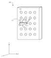
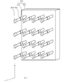
- FIG. 1A is a perspective view of a cold insulation jig according to the first embodiment.
- FIG. 1B is a schematic view for explaining a method of fixing a pin to a cold insulation jig according to the first embodiment.
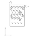
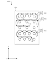
- FIG. 2A is a front view when the cold insulator is installed on the jig for the cold insulator according to the first embodiment.
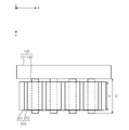
- FIG. 2B is a top view when the cooler is installed on the jig for the cooler according to the first embodiment.
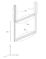
- FIG. 3A is a perspective view of a cold insulation jig of a comparative example of the first embodiment.
- FIG. 3B is a front view when the cold insulator is installed on the jig for the cold insulator of the comparative example of the first embodiment.
- FIG. 1A is a perspective view of a cold insulation jig according to the first embodiment.
- FIG. 1B is a schematic view for explaining a method of fixing a pin to a cold insulation j
- FIG. 4A is a perspective view of the cold insulation jig according to the second embodiment.
- FIG. 4B is a schematic view for explaining a method of fixing a pin to a cold insulation jig according to the second embodiment.
- FIG. 4C is a front view when the cold insulator is installed on the jig for the cold insulator according to the second embodiment.
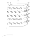
- FIG. 5A is a perspective view of the cold insulation jig according to the third embodiment.
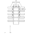
- FIG. 5B is a top view when the cooler is installed on the jig for the cooler according to the third embodiment.
- FIG. 6A is a perspective view of the cold insulation jig according to the fourth embodiment.
- FIG. 6B is a top view when the cooler is installed on the jig for the cooler according to the fourth embodiment.
- FIG. 7 is a schematic view of the freezer according to the fifth embodiment.
- FIG. 8 is a schematic view of the carrier according to the sixth embodiment.
- the x-axis indicates the horizontal direction
- the y-axis indicates the horizontal direction orthogonal to the x-axis
- the z-axis indicates the vertical direction
- FIG. 1A is a perspective view of the cold insulation jig 100 according to the present embodiment.
- FIG. 1B is a schematic view for explaining a method of fixing a pin to the cold insulation jig 100 according to the present embodiment.
- FIG. 2A is a front view when the cold insulation tool 200 is installed on the cold insulation tool jig 100 according to the present embodiment.
- FIG. 2B is a top view when the cold insulation tool 200 is installed on the cold insulation tool jig 100 according to the present embodiment.
- the cold insulation jig 100 supports a plurality of rod-shaped pin portions 102 and one ends of the plurality of pin portions 102 for holding at least one cold insulation tool 200.
- the support portion 101 is provided.
- the pin portion 102 is shaped like a cylinder in order to reduce the number of contact points with the cold insulation tool 200.
- a plurality of cold storage portions 201 each holding a cold storage material inside are connected by a plurality of flexible connecting portions 202.
- Each of the plurality of pin portions 102 is supported by the support portion 101 in a predetermined pattern described later so that the plurality of cold storage portions 201 do not overlap each other when holding the cold insulation tool 200.
- the cold storage material is, for example, a material that changes its shape from a liquid to a solid when the temperature becomes low.
- the material of the support portion 101 is a cold-resistant metal or plastic that does not easily become brittle even at low temperatures.
- the material of the pin portion 102 is metal or plastic, which has cold resistance and does not easily become brittle even at low temperatures.
- the heat conductivity is high and the surface temperature is lowered by the cold air. More desirable is a metal such as aluminum or copper, which is easy to use.
- the pin portion 102 has a hollow structure or a hollow honeycomb structure.
- the surface temperature of the pin portion 102 tends to approach the temperature of the surrounding air, and freezing of the cold insulator 200 can be promoted.
- the pin portion 102 has a hollow structure or a hollow honeycomb structure, it is possible to reduce the physical load on the support portion 101 due to the weight of the pin portion 102.
- the central portion of the cold storage portion 201 is placed on the pin portion 102, and the cold insulation tool 200 is stably installed on the cold insulation tool jig 100. It becomes possible. Further, the length l2 of the pin portion 102 is longer than the long side l1 of the cold storage tool 200 so that it does not easily fall off from the cold storage tool jig 100.
- a plurality of pin portions 102 are installed side by side in the x-axis direction and the y-axis direction. Therefore, even with respect to the cold storage tool 200 to which a large number of cold storage portions 201 are connected, it is possible to meander and arrange the cold storage tool 200 in the cold storage tool jig 100, and the cold storage tool jig 100 is a single cold storage tool 200. Can be frozen without contact.
- the pin portion 102 may be configured to be detachably supported by the support portion 101 via the hole portion 103.
- the hole 103 may or may not penetrate the support 101, but the pin 102 does not protrude from the back surface when the pin 102 is fixed.
- the pin portion 102 is prevented from protruding from the back surface so that the back surface of the cold insulation jig 100 is adhered to the wall to prevent it from falling over.
- the pin portion 102 is provided with a fitting portion 104 that can be fitted into the hole portion 103.
- the hole 103 may be threaded
- the fitting 104 may be threaded
- the hole 103 and the fitting 104 may be fixed like nuts and bolts.
- the pin portion 102 is fixed to all the hole portions 103, and the pin portion 102 may be fixed to only some of the hole portions 103. Further, since the arrangement of the pin portion 102 can be changed by fitting the fitting portion 104 into the hole portion 103, the cold insulation jig 100 can correspond to the cold insulation tool 200 having different dimensions.
- a plurality of pin portions 102 are arranged on the support portion 101 with a first interval d1 and a second interval d2 separated from each other, so that the portions of the single cooling jig 200 can be separated from each other.
- the plurality of cold storage devices 200 can be arranged on the cold storage device jig 100 so that they do not overlap with each other. Thereby, when the cold storage device 200 is frozen, it is possible to prevent the plurality of cold storage tools 200 and the portions of the single cold storage tool 200 from sticking to each other due to freezing of water droplets adhering to the surface of the cold storage tool 200.
- the pin portion 102 has a cylindrical shape with a diameter of 20 mm and a length of l2 of 225 mm, and is made of hollow aluminum having a thickness of 1.5 mm.
- the cold insulation jig 100 of the embodiment includes four pin portions 102 so that the interval d1 is 40 mm in the x-axis direction and five pins so that the interval d2 is 40 mm in the z-axis direction, for a total of 20 pins. I did it.
- FIGS. 3A and 3B As a comparative example, the cold insulation jig 300 is shown in FIGS. 3A and 3B.
- FIG. 3A is a perspective view of the cold insulation jig 300 of the comparative example of the present embodiment.
- FIG. 3B is a front view when the cold insulation tool 200 is installed on the cold insulation tool jig 300 of the comparative example of the present embodiment.
- the cold storage device 200 When the worker freezes the cold storage device 200 without using the cold storage device jig 300, it is conceivable to install the cold storage device 200 directly on the floor or shelf in the freezer, for example. In this case, if water droplets or the like are attached to the cooler 200, the cooler 200 will stick to the floor or the shelf in the freezer, and the cooler 200 will be damaged when the operator takes out the cooler 200 from the freezer. There is a possibility that it will end up.
- the cold insulation jig 300 includes a hook portion 302 and a partition portion 303.
- the cold insulation tool 200 can be hooked on the hook portion 302, and when the operator freezes the cold insulation tool 200 using the cold insulation tool jig 300, the cold insulation tool 200 is installed directly in the freezer. In comparison, the possibility of damage to the cold insulation device 200 can be reduced.
- the partition portion 303 serves as a partition between the cold storage portions 201 of the cold storage device 200 in the hooked state, the cold storage sections 201 are frozen by water droplets or the like as compared with the case where the cold storage device 200 is directly installed in the freezer. It is possible to prevent it from sticking to the edge.
- the cold storage units 201 may freeze in contact with each other, and the cold storage units 201 may stick to each other due to water droplets. If the cold storage portions 201 stick to each other, the packaging material of the cold insulation tool 200 may be damaged when the cold storage portions 201 are peeled off.
- the cold insulation jig 300 is formed by, for example, forming an iron wire having a circular cross section and a diameter of 2.0 mm along the outer circumference of a rectangle having a short side of 100 mm and a long side of 225 mm. Further, the cold insulation jig 300 is hung in the freezer by the hanging portion 301.
- the cold storage material held inside by one cold storage unit 201 was 96 g of water.
- the dimensions of the cold storage portion 201 were 50 mm on the short side, 195 mm on the long side l1, and 17 mm in thickness, and the dimensions of the connecting portion 202 were 10 mm on the short side and 195 mm on the long side l1.
- the packaging material of the cold insulation tool 200 was a nylon film, and the cold insulation tool 200 was assumed to have 10 cold storage portions 201 connected to each other.
- the two ice packs 200 were installed on the ice pack jig 100 as shown in FIG. 2A.
- the cold insulation tool 200 is installed on the cold insulation tool jig 100 so that all the cold storage portions 201 are placed on the upper part of the pin portion 102 and the cold insulation tools 200 do not come into contact with each other.
- the cold storage jig 100 on which the two cold storage devices 200 were installed was allowed to stand in the freezer at ⁇ 25 ° C. for 3 hours, and the two cold storage devices 200 were frozen.
- the method of this example after freezing, sticking due to freezing of water droplets on the surface between the same cold storage devices 200 or between the plurality of cold storage devices 200 did not occur. This is because the cold storage portions 201 could be frozen without any contact with each other.
- one cooler 200 is suspended so that the connecting portion 202 is hooked on the hooking portion 302, and is allowed to stand in the freezer at -25 ° C for 3 hours, and one cooler 200 is frozen. did.
- the cold storage device 200 was stuck due to freezing of water droplets on the surface due to contact between the cold storage portions 201 at both ends constituting the single cold storage device 200 after freezing.
- the plurality of pin portions 102 and 410 have two types of spacing d1 and spacing d2 in the x-axis direction. It is installed at intervals of. Specifically, for example, as shown in FIG. 1B above, the pin portions 102 and 410 are installed by fixing the pin portions 102 and 410 at two types of intervals in the x-axis direction among the plurality of holes of the support portion 101. ..
- the pin portion 410 is a fixing portion 411 for fixing the two fitting portions 104 and the two fitting portions as shown in FIG. 4B, which is a schematic view for explaining a method of fixing the pin to the cold insulation jig according to the embodiment. It may be configured to include.
- the pin portion 410 is supported by the support portion 101 by fitting the two fitting portions 104 into the corresponding hole portions 103, respectively. Since a plurality of pin portions 102 and 410 are installed at two types of intervals in the same direction, the cold storage jig 400 in the present embodiment includes the cold storage tools 200 and 420 as shown in FIG. 4C having different dimensions. Can be installed.
- FIG. 4C is a front view when the cold insulators 200 and 420 are installed on the cold insulator jig 400 according to the present embodiment.
- two cold insulation tools 200 and a cold insulation tool 420 are installed in the cold insulation tool jig 400.
- the cold storage section 422 is larger than the cold storage section 201, and a pin section 410 is used to place the central portion of the cold storage section 422 in order to reduce the number of contact points when freezing.
- a plurality of cold storage portions 422 each holding a cold storage material inside are connected by a plurality of flexible connecting portions 421.
- pin portion 410 is used as an example is described in FIG. 4B described above, when a sufficient number of hole portions 103 are provided in the support portions 101, a predetermined hole portion 103 is selected and the pin portion 102 is used. Just fit it in.
- first intervals d1 may not all be the same, for example, only the first interval d1 in the central portion may be wider than the other first intervals d1.
- each second interval d2 does not have to be the same interval.
- each third interval d3 does not have to be the same interval.
- the pin portions 102 and 410 have a rod-like shape, but in the second embodiment, the pin portions 502 have protrusions 503 and 504 as shown in FIGS. 5A and 5B, for example. Is different from the above-described embodiment. In the following, description of the same points as in the first embodiment will be omitted.
- the protrusion 503 may be referred to as a first protrusion
- the protrusion 504 may be referred to as a second protrusion.
- FIG. 5A is a perspective view of the cold insulation jig 500 according to the present embodiment.
- FIG. 5B is a top view when the cold insulation tool 200 is installed on the cold insulation tool jig 500 according to the present embodiment.
- the cold insulation jig 500 according to the present embodiment supports a plurality of rod-shaped pin portions 502 and one ends of the plurality of pin portions 502 for holding at least one cold insulation tool 200.
- a support portion 501 is provided.
- a plurality of cold storage portions 201 each holding a cold storage material inside are connected by a plurality of flexible connecting portions 202.
- Each of the plurality of pin portions 502 is supported by the support portion 501 in a predetermined pattern so that the plurality of cold storage portions 201 do not overlap each other when holding the cold insulation tool 200.
- the pin portion 502 has a protrusion 503 having a cross-sectional area larger than the cross-sectional area of the pin portion 502 at a predetermined distance from one end of the pin portion 502. Further, the pin portion 502 has a protrusion 504 having a cross-sectional area larger than the cross-sectional area of the pin portion 502 at the other end of the pin portion 502.
- the protrusions 503 serve as a partition for partitioning the different cooling tools 200, so that the different cooling tools 200 are separated from each other. Is hard to stick due to freezing of water droplets adhering to the cold insulator 200.
- the protrusion 504 makes it difficult for the cold storage tool 200 to drop from the cold storage tool jig 500 when the cold storage tool 200 is moved together with the cold storage tool jig 500 after freezing. Further, the protrusion 504 makes it difficult for the cold insulation tool 200 to drop from the cold insulation tool jig 500 even when vibration is applied to the cold insulation tool jig 500 due to an earthquake or the like while the cold insulation tool 200 is frozen. ..
- the number of protrusions 503 located in the middle of one pin portion 502 is one, but the present embodiment is not limited to this, and there may be a plurality of protrusions 503 located in the middle of one pin portion 502.
- the number of cold insulators 200 that can be frozen at one time by the cold insulator jig 500 increases.
- the material of the pin portion 502 may be the same as that of the first embodiment, including the protrusions 503 and 504, but for example, only the protrusions 503 and 504 may be made of plastic and the other parts may be made of metal. .. By making only the protrusions 503 and 504 plastic, the protrusions 503 and 504 can be wound around metal, and the protrusions 503 and 504 can be easily processed.
- the cooler 200 can be arranged so that the portions of the single cooler 200 and the plurality of cooler 200 do not overlap each other. Therefore, when the cold storage jig 500 on which the cold storage 200 is installed is installed in the freezer, it is possible to secure an area of the cold storage 200 that comes into contact with cold air.
- the pin portions 102, 410 and 502 are provided only on the front surface of the support portions 101 and 501, but in the third embodiment, for example, FIG. 6A, As shown in FIG. 6B, the pin portion 603 is provided on the side surface portion of the support portion 601 different from the above embodiment. In the following, description of the same points as in the first embodiment will be omitted.
Landscapes
- Engineering & Computer Science (AREA)
- Physics & Mathematics (AREA)
- Mechanical Engineering (AREA)
- Thermal Sciences (AREA)
- General Engineering & Computer Science (AREA)
- Chemical & Material Sciences (AREA)
- Combustion & Propulsion (AREA)
Abstract
La présente invention concerne un gabarit d'outil d'isolation à froid qui peut empêcher une pluralité d'outils ou sections d'isolation à froid d'un seul outil d'isolation à froid, lors de la congélation, de se coller en raison de gouttes d'eau adhérant à l'outil d'isolation à froid. Un gabarit d'outil d'isolation à froid selon un mode de réalisation de la présente invention comprend : une pluralité de parties broches en forme de tige qui maintiennent au moins un outil d'isolation à froid dans lequel une pluralité de parties de stockage de froid, chacune contenant en son sein un matériau de stockage de froid, sont raccordées par une pluralité de parties de raccordement flexibles ; et une partie de support qui supporte une extrémité de la pluralité de parties broches, chacune de la pluralité de parties broches étant supportée par la partie de support selon un motif prescrit de telle sorte que la pluralité de parties de stockage de froid ne se chevauchent pas les unes avec les autres lorsque la pluralité de parties broches maintiennent l'outil d'isolation à froid.
Applications Claiming Priority (2)
| Application Number | Priority Date | Filing Date | Title |
|---|---|---|---|
| JP2019111778 | 2019-06-17 | ||
| JP2019-111778 | 2019-06-17 |
Publications (1)
| Publication Number | Publication Date |
|---|---|
| WO2020255583A1 true WO2020255583A1 (fr) | 2020-12-24 |
Family
ID=74040485
Family Applications (1)
| Application Number | Title | Priority Date | Filing Date |
|---|---|---|---|
| PCT/JP2020/018822 Ceased WO2020255583A1 (fr) | 2019-06-17 | 2020-05-11 | Gabarit d'outil d'isolation à froid, chambre de congélateur et outil de transport |
Country Status (1)
| Country | Link |
|---|---|
| WO (1) | WO2020255583A1 (fr) |
Citations (10)
| Publication number | Priority date | Publication date | Assignee | Title |
|---|---|---|---|---|
| JPS52103264A (en) * | 1976-02-24 | 1977-08-30 | Prima Meat Packers Ltd | Commodity display instrument |
| JPS5724985U (fr) * | 1980-07-10 | 1982-02-09 | ||
| JPH0556834A (ja) * | 1991-07-03 | 1993-03-09 | Fuji Electric Co Ltd | オープンシヨーケースの商品陳列棚 |
| JPH10220960A (ja) * | 1997-01-31 | 1998-08-21 | Sanyo Electric Co Ltd | 冷却貯蔵庫および蓄冷剤用支持部材 |
| US6085916A (en) * | 1998-03-27 | 2000-07-11 | Seven Continents Enterprises Incorporated | Demountable hanger bar |
| JP2002350030A (ja) * | 2001-05-21 | 2002-12-04 | Daiwa Industries Ltd | 蓄冷装置 |
| CN201503185U (zh) * | 2009-09-08 | 2010-06-09 | 井莉莎 | 简易冰箱外壁挂架 |
| JP2011047632A (ja) * | 2009-08-28 | 2011-03-10 | Kenjiro Yoshioka | 蓄冷部材 |
| JP2012220039A (ja) * | 2011-04-04 | 2012-11-12 | Hoshizaki Electric Co Ltd | 蓄冷剤用ラック |
| JP2015049018A (ja) * | 2013-09-04 | 2015-03-16 | ライジング・サン・ディレクトリー株式会社 | 冷凍倉庫の使用方法、およびその方法に使用する吊り下げ用の蓄冷シート |
-
2020
- 2020-05-11 WO PCT/JP2020/018822 patent/WO2020255583A1/fr not_active Ceased
Patent Citations (10)
| Publication number | Priority date | Publication date | Assignee | Title |
|---|---|---|---|---|
| JPS52103264A (en) * | 1976-02-24 | 1977-08-30 | Prima Meat Packers Ltd | Commodity display instrument |
| JPS5724985U (fr) * | 1980-07-10 | 1982-02-09 | ||
| JPH0556834A (ja) * | 1991-07-03 | 1993-03-09 | Fuji Electric Co Ltd | オープンシヨーケースの商品陳列棚 |
| JPH10220960A (ja) * | 1997-01-31 | 1998-08-21 | Sanyo Electric Co Ltd | 冷却貯蔵庫および蓄冷剤用支持部材 |
| US6085916A (en) * | 1998-03-27 | 2000-07-11 | Seven Continents Enterprises Incorporated | Demountable hanger bar |
| JP2002350030A (ja) * | 2001-05-21 | 2002-12-04 | Daiwa Industries Ltd | 蓄冷装置 |
| JP2011047632A (ja) * | 2009-08-28 | 2011-03-10 | Kenjiro Yoshioka | 蓄冷部材 |
| CN201503185U (zh) * | 2009-09-08 | 2010-06-09 | 井莉莎 | 简易冰箱外壁挂架 |
| JP2012220039A (ja) * | 2011-04-04 | 2012-11-12 | Hoshizaki Electric Co Ltd | 蓄冷剤用ラック |
| JP2015049018A (ja) * | 2013-09-04 | 2015-03-16 | ライジング・サン・ディレクトリー株式会社 | 冷凍倉庫の使用方法、およびその方法に使用する吊り下げ用の蓄冷シート |
Similar Documents
| Publication | Publication Date | Title |
|---|---|---|
| CN102461358B (zh) | 安装和移除架空冷却设备的方法和装置 | |
| CA2475656A1 (fr) | Ferrures et methodes de retenue de fils utilisant la force magnetique | |
| CN210050980U (zh) | 一种空调挂机立式电器架 | |
| JP2015122166A (ja) | 電池用ラックおよび電池用ラックに配置した二次電池の冷却方法 | |
| US20150285406A1 (en) | Cable Management Device | |
| KR101393676B1 (ko) | 차량용 부품 거치대 | |
| KR200487579Y1 (ko) | 기판 운반 카세트 | |
| CN103448986A (zh) | 一种储料架 | |
| KR20110090101A (ko) | 박판수납카세트 | |
| CN223939716U (zh) | 一种肉制品冷藏装置 | |
| JP2019219123A (ja) | 保冷構造 | |
| JP2014185827A (ja) | 定温保持具 | |
| JP2003065667A (ja) | 冷却用コンテナの蓄冷剤収納籠 | |
| JP2015049018A (ja) | 冷凍倉庫の使用方法、およびその方法に使用する吊り下げ用の蓄冷シート | |
| KR101426620B1 (ko) | 아이스링크 빙상용 냉각관 지지대 | |
| JPH10220960A (ja) | 冷却貯蔵庫および蓄冷剤用支持部材 | |
| KR101385186B1 (ko) | 전동 행거 | |
| CN209921817U (zh) | 蓄冷剂处理架 | |
| JPH0633150B2 (ja) | 油冷却系の管束位置転換装置 | |
| CN222157511U (zh) | 一种挂线推车的可调节挂线结构 | |
| CN204433564U (zh) | 稳固式仓储货架 | |
| KR200463581Y1 (ko) | 압축기와 증발기 유닛의 장탈착 및 이송에 사용되는 지그 | |
| CN222942113U (zh) | 一种手套支架 | |
| CN205403303U (zh) | 一种螺旋速冻机 | |
| KR100635349B1 (ko) | 냉장고의 응축기 체결용 브라켓 및 이를 이용한 응축기지지장치 |
Legal Events
| Date | Code | Title | Description |
|---|---|---|---|
| 121 | Ep: the epo has been informed by wipo that ep was designated in this application |
Ref document number: 20826511 Country of ref document: EP Kind code of ref document: A1 |
|
| NENP | Non-entry into the national phase |
Ref country code: DE |
|
| 122 | Ep: pct application non-entry in european phase |
Ref document number: 20826511 Country of ref document: EP Kind code of ref document: A1 |
|
| NENP | Non-entry into the national phase |
Ref country code: JP |