WO2020255687A1 - Filtre à particules - Google Patents
Filtre à particules Download PDFInfo
- Publication number
- WO2020255687A1 WO2020255687A1 PCT/JP2020/021608 JP2020021608W WO2020255687A1 WO 2020255687 A1 WO2020255687 A1 WO 2020255687A1 JP 2020021608 W JP2020021608 W JP 2020021608W WO 2020255687 A1 WO2020255687 A1 WO 2020255687A1
- Authority
- WO
- WIPO (PCT)
- Prior art keywords
- layer
- partition wall
- particulate filter
- entry
- exhaust gas
- Prior art date
- Legal status (The legal status is an assumption and is not a legal conclusion. Google has not performed a legal analysis and makes no representation as to the accuracy of the status listed.)
- Ceased
Links
Images




Classifications
-
- B—PERFORMING OPERATIONS; TRANSPORTING
- B01—PHYSICAL OR CHEMICAL PROCESSES OR APPARATUS IN GENERAL
- B01D—SEPARATION
- B01D46/00—Filters or filtering processes specially modified for separating dispersed particles from gases or vapours
- B01D46/66—Regeneration of the filtering material or filter elements inside the filter
- B01D46/80—Chemical processes for the removal of the retained particles, e.g. by burning
- B01D46/82—Chemical processes for the removal of the retained particles, e.g. by burning with catalysts
-
- B—PERFORMING OPERATIONS; TRANSPORTING
- B01—PHYSICAL OR CHEMICAL PROCESSES OR APPARATUS IN GENERAL
- B01D—SEPARATION
- B01D39/00—Filtering material for liquid or gaseous fluids
- B01D39/14—Other self-supporting filtering material ; Other filtering material
- B01D39/20—Other self-supporting filtering material ; Other filtering material of inorganic material, e.g. asbestos paper, metallic filtering material of non-woven wires
- B01D39/2068—Other inorganic materials, e.g. ceramics
-
- B—PERFORMING OPERATIONS; TRANSPORTING
- B01—PHYSICAL OR CHEMICAL PROCESSES OR APPARATUS IN GENERAL
- B01D—SEPARATION
- B01D46/00—Filters or filtering processes specially modified for separating dispersed particles from gases or vapours
- B01D46/24—Particle separators, e.g. dust precipitators, using rigid hollow filter bodies
- B01D46/2403—Particle separators, e.g. dust precipitators, using rigid hollow filter bodies characterised by the physical shape or structure of the filtering element
- B01D46/2418—Honeycomb filters
-
- B—PERFORMING OPERATIONS; TRANSPORTING
- B01—PHYSICAL OR CHEMICAL PROCESSES OR APPARATUS IN GENERAL
- B01D—SEPARATION
- B01D53/00—Separation of gases or vapours; Recovering vapours of volatile solvents from gases; Chemical or biological purification of waste gases, e.g. engine exhaust gases, smoke, fumes, flue gases, aerosols
- B01D53/34—Chemical or biological purification of waste gases
- B01D53/92—Chemical or biological purification of waste gases of engine exhaust gases
- B01D53/94—Chemical or biological purification of waste gases of engine exhaust gases by catalytic processes
- B01D53/944—Simultaneously removing carbon monoxide, hydrocarbons or carbon making use of oxidation catalysts
-
- B—PERFORMING OPERATIONS; TRANSPORTING
- B01—PHYSICAL OR CHEMICAL PROCESSES OR APPARATUS IN GENERAL
- B01D—SEPARATION
- B01D53/00—Separation of gases or vapours; Recovering vapours of volatile solvents from gases; Chemical or biological purification of waste gases, e.g. engine exhaust gases, smoke, fumes, flue gases, aerosols
- B01D53/34—Chemical or biological purification of waste gases
- B01D53/92—Chemical or biological purification of waste gases of engine exhaust gases
- B01D53/94—Chemical or biological purification of waste gases of engine exhaust gases by catalytic processes
- B01D53/9459—Removing one or more of nitrogen oxides, carbon monoxide, or hydrocarbons by multiple successive catalytic functions; systems with more than one different function, e.g. zone coated catalysts
- B01D53/9463—Removing one or more of nitrogen oxides, carbon monoxide, or hydrocarbons by multiple successive catalytic functions; systems with more than one different function, e.g. zone coated catalysts with catalysts positioned on one brick
- B01D53/9472—Removing one or more of nitrogen oxides, carbon monoxide, or hydrocarbons by multiple successive catalytic functions; systems with more than one different function, e.g. zone coated catalysts with catalysts positioned on one brick in different zones
-
- B—PERFORMING OPERATIONS; TRANSPORTING
- B01—PHYSICAL OR CHEMICAL PROCESSES OR APPARATUS IN GENERAL
- B01J—CHEMICAL OR PHYSICAL PROCESSES, e.g. CATALYSIS OR COLLOID CHEMISTRY; THEIR RELEVANT APPARATUS
- B01J23/00—Catalysts comprising metals or metal oxides or hydroxides, not provided for in group B01J21/00
- B01J23/38—Catalysts comprising metals or metal oxides or hydroxides, not provided for in group B01J21/00 of noble metals
- B01J23/54—Catalysts comprising metals or metal oxides or hydroxides, not provided for in group B01J21/00 of noble metals combined with metals, oxides or hydroxides provided for in groups B01J23/02 - B01J23/36
- B01J23/56—Platinum group metals
- B01J23/58—Platinum group metals with alkali- or alkaline earth metals
-
- B—PERFORMING OPERATIONS; TRANSPORTING
- B01—PHYSICAL OR CHEMICAL PROCESSES OR APPARATUS IN GENERAL
- B01J—CHEMICAL OR PHYSICAL PROCESSES, e.g. CATALYSIS OR COLLOID CHEMISTRY; THEIR RELEVANT APPARATUS
- B01J35/00—Catalysts, in general, characterised by their form or physical properties
- B01J35/50—Catalysts, in general, characterised by their form or physical properties characterised by their shape or configuration
- B01J35/56—Foraminous structures having flow-through passages or channels, e.g. grids or three-dimensional [3D] monoliths
-
- F—MECHANICAL ENGINEERING; LIGHTING; HEATING; WEAPONS; BLASTING
- F01—MACHINES OR ENGINES IN GENERAL; ENGINE PLANTS IN GENERAL; STEAM ENGINES
- F01N—GAS-FLOW SILENCERS OR EXHAUST APPARATUS FOR MACHINES OR ENGINES IN GENERAL; GAS-FLOW SILENCERS OR EXHAUST APPARATUS FOR INTERNAL-COMBUSTION ENGINES
- F01N3/00—Exhaust or silencing apparatus having means for purifying, rendering innocuous, or otherwise treating exhaust
- F01N3/02—Exhaust or silencing apparatus having means for purifying, rendering innocuous, or otherwise treating exhaust for cooling, or for removing solid constituents of, exhaust
- F01N3/021—Exhaust or silencing apparatus having means for purifying, rendering innocuous, or otherwise treating exhaust for cooling, or for removing solid constituents of, exhaust by means of filters
- F01N3/022—Exhaust or silencing apparatus having means for purifying, rendering innocuous, or otherwise treating exhaust for cooling, or for removing solid constituents of, exhaust by means of filters characterised by specially adapted filtering structure, e.g. honeycomb, mesh or fibrous
- F01N3/0222—Exhaust or silencing apparatus having means for purifying, rendering innocuous, or otherwise treating exhaust for cooling, or for removing solid constituents of, exhaust by means of filters characterised by specially adapted filtering structure, e.g. honeycomb, mesh or fibrous the structure being monolithic, e.g. honeycombs
-
- F—MECHANICAL ENGINEERING; LIGHTING; HEATING; WEAPONS; BLASTING
- F01—MACHINES OR ENGINES IN GENERAL; ENGINE PLANTS IN GENERAL; STEAM ENGINES
- F01N—GAS-FLOW SILENCERS OR EXHAUST APPARATUS FOR MACHINES OR ENGINES IN GENERAL; GAS-FLOW SILENCERS OR EXHAUST APPARATUS FOR INTERNAL-COMBUSTION ENGINES
- F01N3/00—Exhaust or silencing apparatus having means for purifying, rendering innocuous, or otherwise treating exhaust
- F01N3/02—Exhaust or silencing apparatus having means for purifying, rendering innocuous, or otherwise treating exhaust for cooling, or for removing solid constituents of, exhaust
- F01N3/021—Exhaust or silencing apparatus having means for purifying, rendering innocuous, or otherwise treating exhaust for cooling, or for removing solid constituents of, exhaust by means of filters
- F01N3/033—Exhaust or silencing apparatus having means for purifying, rendering innocuous, or otherwise treating exhaust for cooling, or for removing solid constituents of, exhaust by means of filters in combination with other devices
- F01N3/035—Exhaust or silencing apparatus having means for purifying, rendering innocuous, or otherwise treating exhaust for cooling, or for removing solid constituents of, exhaust by means of filters in combination with other devices with catalytic reactors
-
- B—PERFORMING OPERATIONS; TRANSPORTING
- B01—PHYSICAL OR CHEMICAL PROCESSES OR APPARATUS IN GENERAL
- B01D—SEPARATION
- B01D2239/00—Aspects relating to filtering material for liquid or gaseous fluids
- B01D2239/04—Additives and treatments of the filtering material
-
- B—PERFORMING OPERATIONS; TRANSPORTING
- B01—PHYSICAL OR CHEMICAL PROCESSES OR APPARATUS IN GENERAL
- B01D—SEPARATION
- B01D2239/00—Aspects relating to filtering material for liquid or gaseous fluids
- B01D2239/04—Additives and treatments of the filtering material
- B01D2239/0471—Surface coating material
- B01D2239/0478—Surface coating material on a layer of the filter
-
- B—PERFORMING OPERATIONS; TRANSPORTING
- B01—PHYSICAL OR CHEMICAL PROCESSES OR APPARATUS IN GENERAL
- B01D—SEPARATION
- B01D2255/00—Catalysts
- B01D2255/10—Noble metals or compounds thereof
- B01D2255/102—Platinum group metals
- B01D2255/1021—Platinum
-
- B—PERFORMING OPERATIONS; TRANSPORTING
- B01—PHYSICAL OR CHEMICAL PROCESSES OR APPARATUS IN GENERAL
- B01D—SEPARATION
- B01D2255/00—Catalysts
- B01D2255/10—Noble metals or compounds thereof
- B01D2255/102—Platinum group metals
- B01D2255/1023—Palladium
-
- B—PERFORMING OPERATIONS; TRANSPORTING
- B01—PHYSICAL OR CHEMICAL PROCESSES OR APPARATUS IN GENERAL
- B01D—SEPARATION
- B01D2255/00—Catalysts
- B01D2255/10—Noble metals or compounds thereof
- B01D2255/102—Platinum group metals
- B01D2255/1025—Rhodium
-
- B—PERFORMING OPERATIONS; TRANSPORTING
- B01—PHYSICAL OR CHEMICAL PROCESSES OR APPARATUS IN GENERAL
- B01D—SEPARATION
- B01D2255/00—Catalysts
- B01D2255/65—Catalysts not containing noble metals
-
- B—PERFORMING OPERATIONS; TRANSPORTING
- B01—PHYSICAL OR CHEMICAL PROCESSES OR APPARATUS IN GENERAL
- B01D—SEPARATION
- B01D2255/00—Catalysts
- B01D2255/90—Physical characteristics of catalysts
- B01D2255/903—Multi-zoned catalysts
- B01D2255/9032—Two zones
-
- B—PERFORMING OPERATIONS; TRANSPORTING
- B01—PHYSICAL OR CHEMICAL PROCESSES OR APPARATUS IN GENERAL
- B01D—SEPARATION
- B01D2255/00—Catalysts
- B01D2255/90—Physical characteristics of catalysts
- B01D2255/903—Multi-zoned catalysts
- B01D2255/9035—Three zones
-
- B—PERFORMING OPERATIONS; TRANSPORTING
- B01—PHYSICAL OR CHEMICAL PROCESSES OR APPARATUS IN GENERAL
- B01D—SEPARATION
- B01D2255/00—Catalysts
- B01D2255/90—Physical characteristics of catalysts
- B01D2255/908—O2-storage component incorporated in the catalyst
-
- B—PERFORMING OPERATIONS; TRANSPORTING
- B01—PHYSICAL OR CHEMICAL PROCESSES OR APPARATUS IN GENERAL
- B01D—SEPARATION
- B01D2255/00—Catalysts
- B01D2255/90—Physical characteristics of catalysts
- B01D2255/91—NOx-storage component incorporated in the catalyst
-
- B—PERFORMING OPERATIONS; TRANSPORTING
- B01—PHYSICAL OR CHEMICAL PROCESSES OR APPARATUS IN GENERAL
- B01D—SEPARATION
- B01D2255/00—Catalysts
- B01D2255/90—Physical characteristics of catalysts
- B01D2255/92—Dimensions
- B01D2255/9205—Porosity
-
- B—PERFORMING OPERATIONS; TRANSPORTING
- B01—PHYSICAL OR CHEMICAL PROCESSES OR APPARATUS IN GENERAL
- B01D—SEPARATION
- B01D2279/00—Filters adapted for separating dispersed particles from gases or vapours specially modified for specific uses
- B01D2279/30—Filters adapted for separating dispersed particles from gases or vapours specially modified for specific uses for treatment of exhaust gases from IC Engines
-
- B—PERFORMING OPERATIONS; TRANSPORTING
- B01—PHYSICAL OR CHEMICAL PROCESSES OR APPARATUS IN GENERAL
- B01D—SEPARATION
- B01D53/00—Separation of gases or vapours; Recovering vapours of volatile solvents from gases; Chemical or biological purification of waste gases, e.g. engine exhaust gases, smoke, fumes, flue gases, aerosols
- B01D53/34—Chemical or biological purification of waste gases
- B01D53/92—Chemical or biological purification of waste gases of engine exhaust gases
- B01D53/94—Chemical or biological purification of waste gases of engine exhaust gases by catalytic processes
- B01D53/9404—Removing only nitrogen compounds
- B01D53/9409—Nitrogen oxides
- B01D53/9413—Processes characterised by a specific catalyst
- B01D53/9418—Processes characterised by a specific catalyst for removing nitrogen oxides by selective catalytic reduction [SCR] using a reducing agent in a lean exhaust gas
-
- B—PERFORMING OPERATIONS; TRANSPORTING
- B01—PHYSICAL OR CHEMICAL PROCESSES OR APPARATUS IN GENERAL
- B01D—SEPARATION
- B01D53/00—Separation of gases or vapours; Recovering vapours of volatile solvents from gases; Chemical or biological purification of waste gases, e.g. engine exhaust gases, smoke, fumes, flue gases, aerosols
- B01D53/34—Chemical or biological purification of waste gases
- B01D53/92—Chemical or biological purification of waste gases of engine exhaust gases
- B01D53/94—Chemical or biological purification of waste gases of engine exhaust gases by catalytic processes
- B01D53/9404—Removing only nitrogen compounds
- B01D53/9409—Nitrogen oxides
- B01D53/9413—Processes characterised by a specific catalyst
- B01D53/9422—Processes characterised by a specific catalyst for removing nitrogen oxides by NOx storage or reduction by cyclic switching between lean and rich exhaust gases (LNT, NSC, NSR)
-
- F—MECHANICAL ENGINEERING; LIGHTING; HEATING; WEAPONS; BLASTING
- F01—MACHINES OR ENGINES IN GENERAL; ENGINE PLANTS IN GENERAL; STEAM ENGINES
- F01N—GAS-FLOW SILENCERS OR EXHAUST APPARATUS FOR MACHINES OR ENGINES IN GENERAL; GAS-FLOW SILENCERS OR EXHAUST APPARATUS FOR INTERNAL-COMBUSTION ENGINES
- F01N2330/00—Structure of catalyst support or particle filter
- F01N2330/06—Ceramic, e.g. monoliths
-
- F—MECHANICAL ENGINEERING; LIGHTING; HEATING; WEAPONS; BLASTING
- F01—MACHINES OR ENGINES IN GENERAL; ENGINE PLANTS IN GENERAL; STEAM ENGINES
- F01N—GAS-FLOW SILENCERS OR EXHAUST APPARATUS FOR MACHINES OR ENGINES IN GENERAL; GAS-FLOW SILENCERS OR EXHAUST APPARATUS FOR INTERNAL-COMBUSTION ENGINES
- F01N2510/00—Surface coverings
- F01N2510/06—Surface coverings for exhaust purification, e.g. catalytic reaction
- F01N2510/068—Surface coverings for exhaust purification, e.g. catalytic reaction characterised by the distribution of the catalytic coatings
- F01N2510/0682—Surface coverings for exhaust purification, e.g. catalytic reaction characterised by the distribution of the catalytic coatings having a discontinuous, uneven or partially overlapping coating of catalytic material, e.g. higher amount of material upstream than downstream or vice versa
Definitions
- the present invention relates to a particulate filter. More specifically, the present invention relates to a particulate filter that collects particulate matter (PM: Particulate Matter) contained in exhaust gas discharged from an internal combustion engine.
- PM particulate Matter
- Exhaust gas from internal combustion engines that use gasoline or diesel oil as fuel contains carbon as the main component in addition to gaseous components such as hydrocarbons (HC), carbon monoxide (CO), and nitrogen oxides (NOx). It contains particulate matter (hereinafter, also referred to as "PM"). Similar to the gas components such as HC, CO, and NOx, the amount of this PM is determined in consideration of the effect on the human body.
- a particulate filter for collecting PM in the exhaust passage of the internal combustion engine.
- An example of such a particulate filter is a wall flow type filter.
- This wall flow type filter is based on a honeycomb-structured base material having a plurality of hollow portions (cells), and alternately forms an inlet cell with a closed outlet and an outlet cell with a closed inlet. It is built by doing.
- the exhaust gas supplied to the wall flow type filter flows into the inlet side cell, passes through the porous partition wall, and then is discharged to the outside of the filter through the outlet side cell. At this time, PM in the exhaust gas is collected in the pores of the partition wall.
- a wash coat layer may be formed inside the partition wall (wall surface of the pores) in order to improve high temperature stability and PM collection performance.
- Patent Documents 1 and 2 disclose an example of a particulate filter carrying such a noble metal catalyst.
- the present invention has been made in view of such circumstances, and a main object thereof is to provide a particulate filter capable of achieving both PM collection performance and pressure loss suppression performance at a high level.
- the present inventors focused on the following points.
- the early stage of operation which is immediately after the start of operation of the internal combustion engine
- high-temperature exhaust gas with a low PM content is discharged.
- the exhaust gas discharged at the initial stage of operation tends to pass through the partition wall on the upstream side in the gas flow direction because the flow rate is small.
- the exhaust gas discharged in the middle of operation tends to pass through the partition wall on the downstream side because the flow rate is relatively large.
- the present inventors did not allow the noble metal catalyst to exist in the region on the upstream side of the partition wall and the noble metal in the region on the downstream side. I came up with the idea of having a catalyst.
- the PM collection performance is likely to be improved as the amount of PM deposited increases in the region on the upstream side.
- PM can be suitably removed from the exhaust gas at the initial stage of operation, which has a high PM content and passes through the region on the upstream side.
- the particulate filter disclosed here was made based on the above findings.
- a particulate filter is arranged in an exhaust passage of an internal combustion engine and is used to collect particulate matter in the exhaust gas discharged from the internal combustion engine.
- This particulate filter includes an entry-side cell in which only the end on the exhaust gas inflow side is open, an exit-side cell in which only the end on the exhaust gas outflow side is open adjacent to the entry-side cell, and an entry-side cell and an exit-side cell. It is provided with a base material having a wall flow structure having a porous partition wall for partitioning the partition wall, and a wash coat layer formed inside the partition wall.
- the wash coat layer is formed with a predetermined thickness from the surface of the partition wall in contact with the entry side cell to the inside of the partition wall, and has a predetermined length from the vicinity of the end portion on the exhaust gas inflow side along the extension direction of the partition wall. It is formed with a predetermined thickness from the surface of the partition wall in contact with the formed entry-side layer and the exit-side cell to the inside of the partition wall, and has a predetermined length from the vicinity of the end on the exhaust gas outflow side along the extension direction of the partition wall.
- the thickness and length of each of the entry-side layer and the exit-side layer are set so that the entry-side layer and the exit-side layer partially overlap with each other.
- the PM collection performance in the entry side region where the noble metal catalyst is substantially not present is likely to be improved, so that PM can be suitably removed from the exhaust gas at the initial stage of operation. Further, since the gas flowability in the output side region where the noble metal catalyst is present is maintained in a high state, it is possible to appropriately suppress a rapid increase in pressure loss even if exhaust gas in the middle stage of operation having a large flow rate is supplied. As described above, according to the particulate filter disclosed herein, both PM collection performance and pressure loss suppression performance can be achieved at a high level.
- an entry side region a region in which only the entry side layer is formed and the noble metal catalyst is substantially not present is referred to as an “entry side region”. Further, the region where the exit side layer is formed and the noble metal catalyst is present is referred to as a “exit side region”. That is, in the catalyst filter disclosed herein, the entry side layer and the exit side layer partially overlap in order to avoid the occurrence of a region in which the wash coat layer is not formed. The region that overlaps with the exit side layer is regarded as the “outside region” due to the presence of the precious metal catalyst.
- the content of the noble metal catalyst in the exit layer is 0.1 g / L or more. As a result, the gas flowability in the exit side region can be maintained in a higher state.
- the region of the wash coat layer that does not substantially contain the noble metal catalyst (that is, the entry side region) is formed. , It is formed in a region of 30% or more and 60% or less from the vicinity of the end on the exhaust gas outflow side. As a result, both PM collection performance and pressure loss suppression performance can be achieved at a higher level.
- the entry side layer when the bulkhead thickness is 100%, has a thickness of 75% or more and 100% or less from the surface in contact with the entry side cell to the inside of the partition wall. It is formed. Thereby, the PM collection performance in the entry side region can be more preferably improved.
- the exit layer when the bulkhead thickness is 100%, has a thickness of 75% or more and 100% or less from the surface in contact with the exit cell to the inside of the partition. It is formed. As a result, both PM collection performance and pressure loss suppression performance in the output side region can be achieved at a higher level.
- the ratio (W / V) of the total weight W of the washcoat layer to the effective volume V of the pores of the partition wall in the entire substrate is 200 g / L or more and 400 g / L or less. Is. According to the experiments conducted by the present inventors, by controlling the W / V within a predetermined range, both PM collection performance and pressure loss suppression performance can be achieved at a higher level.
- the noble metal catalyst comprises at least one or more platinum group elements selected from the group Pt, Pd, Rh. Since these platinum group elements are excellent in PM combustion promoting action, the gas flowability in the exit side region can be maintained in a higher state.
- the internal combustion engine is a gasoline engine. Since the exhaust gas from a gasoline engine has a relatively high temperature and PM is easily burned, it tends to be difficult to improve the PM collection performance due to PM accumulation.
- the particulate filter disclosed herein can appropriately deposit PM in the entry side region even when it is arranged in the exhaust passage of such a gasoline engine, so that the particulate filter (GPF: Gasoline) for a gasoline engine can be appropriately deposited. It can be particularly preferably used as a Particulate Filter).
- FIG. 1 is a diagram schematically showing an exhaust system in which a particulate filter according to an embodiment is arranged.
- FIG. 2 is a perspective view schematically showing a particulate filter according to an embodiment.
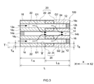
- FIG. 3 is a diagram schematically showing a cross section when the particulate filter according to the embodiment is cut along the stretching direction.
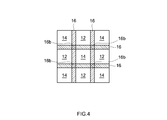
- FIG. 4 is a diagram schematically showing a cross section when the particulate filter according to the embodiment is cut along the radial direction.
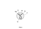
- FIG. 5 is an enlarged cross-sectional schematic view of the V region of FIG.
- FIG. 6 is a graph showing the results of pressure loss measurement of Samples 1 to 4.
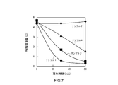
- FIG. 7 is a graph showing the results of PM deposition weights of Samples 1 to 4.
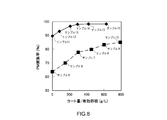
- FIG. 8 is a graph showing the results of PM collection rate measurement of samples 5 to 16.
- FIG. 9 is a graph showing the results of pressure loss measurement of samples 5 to 16.
- FIG. 1 is a diagram schematically showing an exhaust system in which a particulate filter according to the present embodiment is arranged.
- an exhaust gas purification device 1 is provided in the exhaust passage of the internal combustion engine 2.
- An air-fuel mixture containing oxygen and fuel gas is supplied to the internal combustion engine 2.
- the internal combustion engine 2 converts the thermal energy when the air-fuel mixture burns into kinetic energy.
- the exhaust gas generated by the combustion of the air-fuel mixture is discharged to the exhaust passage composed of the exhaust manifold 3 and the exhaust pipe 4.
- the side close to the internal combustion engine 2 in the flow direction of the exhaust gas is referred to as an upstream side, and the side far from the internal combustion engine 2 is referred to as a downstream side.
- the exhaust gas purification device 1 purifies the exhaust gas discharged to the exhaust passage.
- the exhaust gas purification device 1 includes an engine control unit (ECU: Engine Control Unit) 7 and a sensor 8.
- the sensor 8 detects information on the components and temperature of the exhaust gas.
- the ECU 7 receives the detection result of the sensor 8 as one of the information for controlling the operation of the internal combustion engine 2.
- the exhaust gas purification device 1 shown in FIG. 1 includes a catalyst unit 5 and a filter unit 6.
- the catalyst unit 5 is provided inside the exhaust pipe 4.
- An exhaust gas purification catalyst that purifies ternary components (NOx, HC, CO) in the exhaust gas can be used in the catalyst unit 5. Since the specific configuration of the exhaust gas purification catalyst used in the catalyst unit 5 does not characterize the present invention, detailed description thereof will be omitted.
- the catalyst unit 5 is arranged on the upstream side of the filter unit 6, but the arrangement position of the catalyst unit is not particularly limited.
- the catalyst unit may be arranged on the downstream side of the filter unit, or may be arranged in pairs on both the upstream side and the downstream side of the filter unit.
- the filter unit 6 purifies the exhaust gas by collecting particulate matter (PM) in the exhaust gas.
- the particulate filter according to the present embodiment can be used in the filter unit 6 of the exhaust gas purification device 1.
- the particulate filter according to the present embodiment is arranged in the exhaust passage (exhaust pipe 4) of the internal combustion engine 2 as a component of the exhaust gas purification device 1.
- FIGS. 2 and 3 indicate an “exhaust gas distribution direction”.
- the reference numeral X1 indicates an "exhaust gas inflow side (upstream side)”
- the reference numeral X2 indicates an "exhaust gas outflow side (downstream side)”.
- FIG. 2 is a perspective view schematically showing the particulate filter according to the present embodiment.
- FIG. 3 is a diagram schematically showing a cross section when the particulate filter shown in FIG. 2 is cut along the stretching direction (exhaust gas flow direction X), and FIG.
- FIG. 4 is a diagram schematically showing a cross section of the particulate filter in the radial direction (((). It is a figure which shows typically the cross section at the time of cutting along the direction (the direction perpendicular to the flow direction X) of the exhaust gas
- FIG. 5 is the schematic cross-sectional view which enlarged the region V in FIG.
- the particulate filter 100 includes a base material 10 having a wall flow structure and a wash coat layer 20 formed in a partition wall 16 of the base material 10. There is. Each will be described below.
- a cylindrical base material 10 extending along the flow direction X of the exhaust gas is used.
- the base material 10 has a wall flow structure.
- the base material 10 has a honeycomb structure having a plurality of hollow portions (cells 12 and 14). These cells 12 and 14 extend along the flow direction X of the exhaust gas.
- the cells 12 and 14 of the base material 10 in the present embodiment are composed of the entry side cell 12 and the exit side cell 14 adjacent to the entry side cell 12. ..
- the inlet cell 12 and the outlet cell 14 are separated by a porous partition wall 16.
- the material of the base material 10 various materials that can be used for this kind of conventional use can be used without particular limitation.
- the material of the base material 10 include ceramics such as cordierite and silicon carbide (SiC) or alloys (stainless steel and the like).
- the cylindrical base material 10 is used, but the outer shape of the base material is not particularly limited, and may be an elliptical pillar shape, a polygonal pillar shape, or the like.
- the entry-side cell 12 refers to a cell in which only the end of the exhaust gas inflow side X1 is opened among the cells 12 and 14 formed inside the base material 10 (see FIG. 3). That is, in the entry-side cell 12, the end of the exhaust gas inflow side X1 is opened to the outside of the filter as the gas inflow port 12a, and the end of the exhaust gas outflow side X2 is sealed by the sealing portion 12b.
- the exit side cell 14 refers to a cell in which only the end portion of the exhaust gas outflow side X2 is open.
- the end portion of the exhaust gas inflow side X1 is sealed by the sealing portion 14a, and the end portion of the exhaust gas outflow side X2 is opened to the outside of the filter as the gas outlet 14b.
- the shapes and sizes of the inlet cell 12 and the outlet cell 14 can be appropriately changed in consideration of the flow rate and components of the exhaust gas supplied to the particulate filter 100.
- the cross-sectional shapes of the cells 12 and 14 in the cross section orthogonal to the stretching direction X of the base material 10 are square.
- the cross-sectional areas of the entry-side cell 12 and the exit-side cell 14 may be about the same, or may be different in consideration of the flow rate of the exhaust gas.
- the cross-sectional shapes of the cells 12 and 14 are not limited to the square as in the present embodiment, and general shapes such as a parallelogram, a rectangle, a trapezoid, a triangle, a pentagon, and a circle can be adopted without particular limitation. it can.
- the base material 10 is formed so that the entry side cell 12 and the exit side cell 14 are adjacent to each other.
- the base material 10 of the present embodiment is formed so that the entrance cell 12 and the exit cell 14 having a square cross section are arranged in a checkered pattern.
- each of the partition walls 16 formed in a grid pattern extends along the flow direction X of the exhaust gas, and the spaces surrounded by the partition walls 16 are cells 12 and 14 (see FIGS. 3 and 4). ).
- the partition wall 16 has a porous structure having a plurality of pores. Specifically, a plurality of pores 18 as shown in FIG. 5 are formed in the wall body 17 of the partition wall 16, and the entry side cell and the exit side cell communicate with each other through a part of the pores 18. There is. As a result, as shown by the arrow in FIG.
- the exhaust gas that has flowed into the entry-side cell 12 can be passed through the partition wall 16 and flow out to the exit-side cell 14.
- the thickness T and the total length L of the partition wall 16 are preferably adjusted from the viewpoint of achieving both PM collection performance and pressure loss suppression performance.
- the thickness T of the partition wall 16 is preferably about 0.2 mm to 1.6 mm.
- the total length L of the partition wall 16 is preferably about 50 mm to 500 mm (preferably 100 mm to 200 mm).
- the porosity of the partition wall 16 is preferably 40% or more, more preferably 45% or more, further preferably 50% or more, and particularly preferably 55% or more from the viewpoint of suppressing an increase in pressure loss.
- the upper limit of the porosity of the partition wall 16 is preferably 80% or less, more preferably 75% or less, further preferably 70% or less, and particularly preferably 65% or less, from the viewpoint of maintaining the mechanical strength of the base material 10. ..
- the "porosity of the partition wall" in the present specification refers to the ratio of the volume of the pore 18 to the total volume of the partition wall 16 of the base material 10 (the total volume of the wall body 17 and the pore 18), and is based on the mercury intrusion method. It is a measured value.
- the average pore diameter of the pores 18 is preferably 1 ⁇ m or more, more preferably 5 ⁇ m or more, further preferably 7 ⁇ m or more, and particularly preferably 10 ⁇ m or more, from the viewpoint of improving the pressure loss suppressing performance.
- the upper limit of the average pore diameter of the pores 18 is preferably 50 ⁇ m or less, more preferably 40 ⁇ m or less, further preferably 30 ⁇ m or less, and particularly preferably 25 ⁇ m or less.
- the "average pore diameter of the pores 18" in the present specification refers to the average value of the pore distribution obtained by the mercury intrusion method.
- the wash coat layer 20 is a coating layer formed inside the partition wall 16 of the base material 10. Specifically, as shown in FIG. 5, the wash coat layer 20 is a porous heat-resistant layer formed on the wall surface of the pores 18 (the surface of the wall body 17 in contact with the pores 18).
- the wash coat layer 20 may have a function of improving high temperature stability, water absorption, and the like. Further, the wash coat layer 20 can also contribute to the improvement of PM collection performance by increasing the surface area and reducing the diameter of the pores 18.
- Conventionally known materials can be used for the wash coat layer 20 in the present embodiment without particular limitation.
- the wash coat layer 20 is mainly composed of a heat resistant material.
- the wash coat layer 20 preferably contains 50% by mass or more of the heat-resistant material, and more preferably 85% by mass or more.
- a heat-resistant material a refractory material specified in JIS R2001 can be used.
- refractories include neutral refractories such as alumina (Al 2 O 3 ), acidic refractories such as silica (SiO 2 ) and zirconia (ZrO 2 ), and bases such as magnesia (MgO) and calcia (CaO).
- alumina preferably activated alumina is preferable.
- the heat-resistant material of the wash coat layer 20 may be composed of only one of the above-mentioned refractory materials, or may be composed of a mixture (or composite) of two or more types. Examples of the complex include ceria-zirconia composite oxides and the like. Further, the wash coat layer 20 may contain another material (typically an inorganic oxide) as an auxiliary component. Such an example of a sub-component, yttria (Y 2 O 3) rare earth metal oxides such as, and the like alkaline earth metal oxides such as barium oxide (BaO).
- Y 2 O 3 yttria
- rare earth metal oxides such as, and the like alkaline earth metal oxides such as barium oxide (BaO).
- the wash coat layer 20 in the present embodiment includes an entry side layer 22 and an exit side layer 24.
- the thickness and length of the entry-side layer 22 and the exit-side layer 24 are set so that the entry-side layer 22 and the exit-side layer 24 partially overlap each other.
- each layer will be described.
- the entering side layer 22 is a wash coat layer formed in a region including a partition wall 16 near the gas inflow port 12a.
- the inlet side layer 22 is formed at a predetermined thickness T A inwardly of the partition wall 16 from the surface of the partition wall 16 in contact with the inlet side cell 12, and the partition wall 16 from the vicinity of the end portion of the exhaust gas inlet side X1 It is formed with a predetermined length along the stretching direction (exhaust gas flow direction X).
- the thickness T A of the inlet side layer 22, from the viewpoint of improvement of the PM-trapping performance preferably at least 50% of the thickness T of the partition 16, and more preferably 60% or more, more preferably 70% or more, 75% or more Is particularly preferable.
- the upper limit of the thickness T A of the inlet-side layer 22 is not particularly limited, may be less than 100% of the thickness T of the partition 16, it may be 95% or less, 90% or less There may be. As described above, in the present specification, the region in which only the entry side layer 22 is formed is referred to as an “entrance side region”.
- the noble metal catalyst is substantially not contained in the inlet layer 22.
- the precious metal catalyst is a catalyst material having a function of promoting the combustion of PM, and is gold (Au), silver (Ag), palladium (Pd), rhodium (Rh), platinum (Pt), and ruthenium. It contains precious metals such as (Ru), iridium (Ir), and osmium (Os).
- substantially containing no precious metal catalyst means that a component that can be interpreted as a noble metal catalyst is not intentionally added. Therefore, when a component that can be interpreted as a noble metal catalyst is contained in a trace amount due to the raw material, manufacturing process, etc., or when a trace amount of the precious metal catalyst moves from another catalyst layer to the entry side layer (for example, the exit side). (When the noble metal catalyst moves from the layer to the entry side layer) is included in the concept of "substantially containing no noble metal catalyst" in the present specification.
- the ratio (g / L) of the content of the noble metal catalyst to the volume of the entry side layer 22 is 0.05 g / L or less (preferably 0.03 g / L or less, more preferably 0.01 g / L or less, still more preferable. Is 0.005 g / L or less, particularly preferably 0.001 g / L or less), it can be said that "substantially contains no precious metal catalyst".
- the out-side layer 24 is a wash coat layer formed in a region including a partition wall 16 near the gas outlet 14b. Specifically, the exit-side layer 24 is formed from the surface of the partition wall 16 in contact with the exit side cell 14 at a predetermined thickness T B inward of the partition wall 16 and the partition wall from the end portion of the exhaust gas outlet side X2 16 It is formed in a predetermined length L B along the extending direction of the (flow direction X of the exhaust gas). From the viewpoint of improvement of the PM-trapping performance, the thickness T B of the exit-side layer 24 is preferably more than 50% of the thickness T of the partition 16, and more preferably 60% or more, more preferably 70% or more, 75% or more Especially preferable.
- the upper limit of the thickness T B of the exit-side layer 24 is not particularly limited, it may be less than 100% of the thickness T of the partition 16 may be 95% or less, a 90% or less It may be 85% or less.
- a region in which the exit side layer 24 is formed is referred to as a "exit side region”. This "outside region" is assumed to include a region where the entry side layer 22 and the exit side layer 24 overlap.
- the exit side layer 24 contains a noble metal catalyst.
- the noble metal catalyst is a catalyst material having a function of promoting the combustion of PM, and contains at least one kind of noble metal elements such as Au, Ag, Pd, Rh, Pt, Ru, Ir, and Os.
- platinum group elements such as Pt, Pd, and Rh are particularly excellent in the action of promoting PM combustion, and are therefore particularly suitable as precious metals to be contained in the output side layer 24.
- the noble metal catalyst may contain a carrier supporting the noble metal in addition to the above-mentioned noble metal.
- Examples of the material of such a carrier include alumina (Al 2 O 3 ), rare earth metal oxide, alkali metal oxide, alkaline earth metal oxide, zirconia (ZrO 2 ), ceria (CeO 2 ), silica (SiO 2 ), and the like. Examples thereof include magnesia (MgO) and titania (TiO 2 ).
- the content of the noble metal catalyst in the output side layer 24 (ratio of the content g of the noble metal catalyst to the volume of 1 L of the output side layer 24) is preferably 0.1 g / L or more. As a result, the gas flowability in the exit side region can be maintained in a higher state. Further, from the viewpoint of maintaining the gas flowability in the output side region in a higher state, the content of the noble metal catalyst in the output side layer 24 is more preferably 0.5 g / L or more, and further preferably 0.7 g / L or more. Preferably, 1 g / L or more is particularly preferable.
- the upper limit of the content of the noble metal catalyst in the output layer 24 is not particularly limited and may be 20 g / L or less.
- 10 g / L or less is preferable, 7 g / L or less is more preferable, 5 g / L or less is further preferable, and 2 g / L or less is particularly preferable.
- the inlet side region of initial operation of the exhaust gas G1 By ensuring in this manner over a certain length L A of the inlet-side region, it is possible to properly pass the inlet side region of initial operation of the exhaust gas G1.
- the upper limit of the length L A of the inlet-side region is 70% or less, more preferable to be 65% or less, further preferably 60% or less.
- the exit side securing sufficient length L B of the region it is possible to pass the exhaust gas G2 driving medium term to properly exit side region.
- a suitable example of such an entry layer length LA is 55%.
- the inlet side layer 22 does not substantially contain the noble metal catalyst, and the outlet side layer 24 contains the noble metal catalyst.
- both PM collection performance and pressure loss suppression performance can be achieved at a high level.
- the exhaust gas G1 at the initial stage of operation tends to pass through the entry side region of the partition wall 16 because the flow rate is small.
- the exhaust gas G1 at the initial stage of operation contains a relatively large amount of PM, but in the particulate filter 100 according to the present embodiment, PM collection in the entry side region where the noble metal catalyst is substantially not present. Since the performance is likely to be improved, PM can be appropriately removed from the exhaust gas G1 at the initial stage of the operation.
- the flow rate of the exhaust gas G1 at the initial stage of operation is small as described above, a sudden increase in pressure loss is unlikely to occur even when the exhaust gas G1 passes through the entry side region where the pores 18 are maintained in a relatively small state.
- the exhaust gas G2 in the middle stage of operation passes through the exit region of the partition wall 16 due to the large flow rate.
- the gas flowability in the output side region where the precious metal catalyst exists is maintained in a high state, so that even if the exhaust gas in the middle stage of operation with a large flow rate is supplied, a sudden pressure loss occurs. The increase can be suppressed appropriately.
- the exhaust gas G2 in the middle stage of operation has a low PM content, PM can be sufficiently removed even in the exit region where the pores 18 are maintained in a relatively large state.
- the total coat amount of the wash coat layer 20 can affect both the pressure loss suppressing effect and the PM collection performance, and therefore, if necessary. It is preferable that the adjustment is made as appropriate.
- the “total coating amount of the wash coat layer” means the total weight of the wash coat layer 20 including the entry side layer 22 and the exit side layer 24. As the total coating amount increases, the thickness of the wash coat layer 20 adhering to the wall surface of the pores 18 increases, so that the pores 18 have a smaller diameter and the PM collection performance is improved (see FIG. 5).
- the above-mentioned "effective volume V of the pores of the partition wall in the entire base material” is obtained by multiplying the "porosity of the partition wall” and the "volume of the effective partition wall".
- the "porosity of the partition wall” refers to the ratio of the volume of the pore 18 to the total volume of the partition wall 16 of the base material 10 (the total volume of the wall body 17 and the pore 18).
- the "volume of the effective partition wall” refers to the volume of the partition wall through which the exhaust gas can pass.
- the "volume of the effective partition wall” refers to the volume of the partition wall 16 excluding the region through which these exhaust gases do not pass.
- the "volume of the effective partition wall” is obtained by subtracting the volumes of the cells 12 and 14 from the volume of the base material 10. At this time, the "volume of the cells 12 and 14" can be calculated by multiplying the total opening area of the cells 12 and 14 in the front view as shown in FIG. 4 by the total length L of the base material 10.
- the wash coat layer 20 is substantially not present on the surface of the partition wall 16.
- the OSC material is a material that occludes oxygen when the oxygen concentration in the exhaust gas is high (that is, the air-fuel ratio is lean) and releases oxygen when the oxygen concentration in the exhaust gas is low (that is, the air-fuel ratio is rich).
- An example of such an OSC material is a material based on cerium oxide (Ceria: CeO 2 ).
- CeO 2 cerium oxide
- Examples of the material based on CeO 2 include a CZ-based composite material (CeO 2- ZrO 2 composite oxide).
- This CZ-based composite material is a polycrystal or a single crystal containing CeO 2 and ZrO 2 as main components.
- various additional components may be added to the CZ-based composite material. Examples of such additional components include rare earth oxides, alkali metal oxides, alkaline earth metal oxides, transition metals, alumina, silica and the like.
- the OSC material Since the OSC material has the function of maintaining the exhaust gas passing through the partition wall 16 in an oxidizing atmosphere, it can exert a function of promoting the combustion of PM. Therefore, even when the OSC material is used, it is preferable that the entry side layer 22 does not substantially contain the OSC material. As a result, the pressure loss suppression performance and the PM collection performance can be compatible at a higher level.
- the phrase "the inlet layer does not substantially contain the OSC material" means that, like the noble metal catalyst described above, a component that can be interpreted as the OSC material is not intentionally added.
- the ratio (g / L) of the content g of the OSC material to the volume 1 L of the entry side layer 22 is 5 g / L or less (preferably 3 g / L or less, more preferably 2 g / L or less, still more preferably 1 g / L).
- the entry side layer does not substantially contain the OSC material.
- the NOx absorber is a material that absorbs NOx in the exhaust gas when the air-fuel ratio of the exhaust gas is in a lean state of excess oxygen, and releases NOx when the air-fuel ratio becomes rich.
- a basic material containing one or more metals capable of donating electrons to NOx can be preferably used.
- alkali metals such as potassium (K), sodium (Na), cesium (Cs), alkaline earth metals such as barium (Ba), calcium (Ca), rare earths such as lanthanoids and silver (Ag)
- alkali metals such as potassium (K), sodium (Na), cesium (Cs), alkaline earth metals such as barium (Ba), calcium (Ca), rare earths such as lanthanoids and silver (Ag)
- metals such as copper (Cu), iron (Fe), and iridium (Ir).
- a barium compound for example, barium sulfate
- it has a high NOx storage capacity.
- the SCR catalyst may be any one that purifies nitrogen oxides (NOx) in the exhaust gas.
- the SCR catalyst is not particularly limited, and examples thereof include ⁇ -type zeolite and SAPO (silicoaluminophosphate) zeolite.
- SAPO siliconcoaluminophosphate
- Examples of SAPO include SAPO-5, SAPO-11, SAPO-14, SAPO-17, SAPO-18, SAPO-34, SAPO-39, SAPO-42, SAPO-47 and the like.
- SAPO silicon oxides
- the reducing agent supply means for supplying the reducing agent (for example, urea water) for generating ammonia is located upstream of the particulate filter (for example, in FIG. 1). It is preferable to arrange it on the upstream side of the filter unit 5).
- the particulate filter 100 can be arranged in the exhaust passage of the internal combustion engine 2 as a filter unit 5 for removing PM in the exhaust gas (see FIG. 1).
- the particulate filter disclosed herein is not limited to this, and can be used for various purposes.
- the particulate filter disclosed herein contains a noble metal catalyst in the output layer, so that it is a three-way catalyst that purifies hydrocarbons (HC), carbon monoxide (CO), and nitrogen oxides (NOx). Can also function as. Therefore, the particulate filter disclosed herein can also be used as an exhaust gas purification catalyst having both the functions of the catalyst unit 5 and the filter unit 6 in FIG.
- the particulate filter disclosed here is used as a three-way catalyst, it is preferable that the OSC material, NOx absorber, and the like described above are added to the wash coat layer.
- the particulate filter disclosed herein is particularly preferably used when the internal combustion engine 2 is an automobile gasoline engine. Since the exhaust gas discharged from the gasoline engine has a relatively high temperature, PM tends to be difficult to be deposited in the pores of the partition wall. On the other hand, in the particulate filter disclosed here, since the noble metal catalyst is substantially not present in the entry side region, PM can be suitably deposited in the entry side region. Therefore, the particulate filter disclosed herein can suitably improve the PM collection performance even when used in a gasoline engine.
- the particulate filter disclosed here can be used not only for gasoline engines but also for purifying exhaust gas from other engines (for example, diesel engines).
- the SCR device purifies NOx contained in the exhaust gas from the diesel engine.
- particulate filter 100 D. Manufacture of Particulate Filter
- the particulate filter disclosed herein is not limited to the particulate filter manufactured by the following manufacturing method.
- the particulate filter 100 according to the present embodiment can be manufactured, for example, by preparing a slurry containing the material of the wash coat layer 20 and introducing the slurry into the pores 18 of the partition wall 16 of the base material 10.
- each step will be described.
- a slurry is prepared by dispersing the material of the wash coat layer 20 described above in a predetermined dispersion medium.
- a dispersion medium a dispersion medium that can be used for preparing this type of slurry can be used without particular limitation.
- the dispersion medium may be a polar solvent (eg, water) or a non-polar solvent (eg, methanol, etc.).
- the slurry may contain an organic component for adjusting the viscosity in addition to the above-mentioned material and dispersion medium of the wash coat layer 20.
- Examples of the organic component for adjusting the viscosity include cellulosic polymers such as carboxymethyl cellulose (CMC), methyl cellulose (MC), hydroxypropyl methyl cellulose (HPMC), and hydroxyethyl methyl cellulose (HEMC).
- CMC carboxymethyl cellulose
- MC methyl cellulose
- HPMC hydroxypropyl methyl cellulose
- HEMC hydroxyethyl methyl cellulose
- the particulate filter 100 when producing the particulate filter 100 according to the present embodiment, there are two types of slurry, one for the inlet layer which does not substantially contain the noble metal catalyst and the other for the outer layer which contains the noble metal catalyst.
- Prepare the slurry The detailed description of the noble metal catalyst will be omitted because it overlaps with the above description.
- the material other than the noble metal catalyst may be different between the slurry for the inlet side layer and the slurry for the outlet side layer. For example, by making the amount and type of the organic component added for adjusting the viscosity different, the viscosity is made different between the slurry for the inlet layer and the slurry for the outlet layer, and each of the inlet layer and the outlet layer is formed. The area to be subjected to can be easily adjusted.
- the wash coat layer 20 is formed by introducing the above-mentioned slurry into the pores 18 of the partition wall 16.
- the means for introducing the slurry into the pores 18 is not particularly limited, and conventionally known means can be used without particular limitation. Examples of such a slurry introducing means include an air blow method and a suction coating method.
- the air blow method the end portion of the base material 10 is immersed in the slurry to allow the slurry to permeate into the cells 12 and 14, and then the base material 10 is taken out and air blown to introduce the slurry into the pores 18.
- the suction coating method the slurry is introduced into the pores 18 by sucking from the opposite end in a state where the end portion of the base material 10 is immersed in the slurry.
- a wash coat layer 20 having an entry side layer 22 and an exit side layer 24 is formed.
- suction is performed from the gas outlet 14b in a state where the gas inlet 12a of the base material 10 is immersed in the slurry for the inlet layer.
- the slurry for the entry side layer is applied from the vicinity of the end portion of the exhaust gas inflow side X1 to a predetermined length and thickness, and the entry side layer 22 is formed by drying and firing this slurry.
- the gas outlet 14b of the base material 10 is sucked from the gas inlet 12a in a state where the slurry for the outlet layer is immersed.
- the slurry for the output side layer is applied from the vicinity of the end portion of the exhaust gas outflow side X2 to a predetermined length and thickness, and the output side layer 24 is formed by drying and firing this slurry.
- the slurry viscosity and the suction force of the suction coating device to control the area to which each slurry is applied, a part of the inlet side layer 22 and a part of the outlet side layer 24 after firing are formed. Can be duplicated.
- the order in which the entry-side layer 22 and the exit-side layer 24 are formed is not particularly limited, and the entry-side layer 22 may be formed after the exit-side layer 24 is formed. Further, in the above method, the slurry for the inlet side layer is dried and fired to form the inlet side layer 22, and then the slurry for the outlet side layer is introduced into the base material. However, after the slurry for the inlet side layer is dried, the slurry for the outlet side layer may be introduced, and both the slurry for the inlet side layer and the slurry for the outlet side layer may be fired at the same time. Even in these cases, the wash coat layer 20 including the entry side layer 22 and the exit side layer 24 can be formed.
- air blow may be performed after the slurry is introduced and before drying.
- air blow may be performed after the slurry is introduced and before drying.
- the inlet side layer 22 does not substantially contain the noble metal catalyst, and the outlet side layer 24 contains the noble metal catalyst.
- the PM collection performance in the entry side region is likely to be improved, and the pressure drop suppression performance in the exit side region is maintained in a high state. Therefore, the PM collection performance of the filter as a whole is maintained. It is possible to achieve both collection performance and pressure loss suppression performance at a high level.
- test examples relating to the present invention will be described, but the present invention is not intended to be limited to those shown in the following test examples.
- Pd noble metal catalyst
- the Pd-containing slurry was impregnated with the Pd-containing slurry and sucked from the gas inlet to introduce the Pd-containing slurry having a predetermined length and thickness on the downstream side of the partition wall. Then, by drying and firing, a protruding side layer containing a noble metal catalyst (Pd) was formed. Entry side region and out of each side region "length L A, L B", shown in Table 1, "coating amount (introduced slurry weight)" and "content of Pd".
- the sample 4 has a high PM collection performance of 80% or more, and also has a suitable pressure drop suppression performance recovered by the regeneration treatment. It was. For this reason, unlike Sample 4, the particulate filter in which the noble metal catalyst is substantially not contained in the inlet side layer and the noble metal catalyst is contained in the outlet side layer has PM collection performance and pressure drop suppression. It was found that both performance and performance can be achieved at a high level.
- samples 5 to 16 Twelve types of particulate filters (samples 5 to 16) were prepared in which the coating amount of the inlet side layer, the coating amount of the exit side layer, and the type of the base material were different. Details of each sample are shown in Table 2.
- the "base material A” in Table 2 has a wall flow having a partition wall thickness of 0.2 mm to 0.25 mm, a cell number of 300 cpsi, a partition wall porosity of 60% to 65%, and a cell volume of 1.3 L.
- a mold base material manufactured by Cordellite, length 152.4 mm).
- base material B is a wall flow type base material having a partition wall thickness of 0.2 mm to 0.25 mm, a number of cells of 200 cpsi, a partition wall porosity of 55% to 60%, and a cell volume of 1.7 L. (Made by Cordellite, length 152.4 mm).
- the conditions of Samples 5 to 16 other than those shown in Table 1 were set to the same conditions as those of Sample 4 of the first test described above.
Landscapes
- Chemical & Material Sciences (AREA)
- Engineering & Computer Science (AREA)
- Chemical Kinetics & Catalysis (AREA)
- Combustion & Propulsion (AREA)
- Mechanical Engineering (AREA)
- General Engineering & Computer Science (AREA)
- Materials Engineering (AREA)
- Organic Chemistry (AREA)
- Physics & Mathematics (AREA)
- Geometry (AREA)
- Analytical Chemistry (AREA)
- Environmental & Geological Engineering (AREA)
- General Chemical & Material Sciences (AREA)
- Oil, Petroleum & Natural Gas (AREA)
- Health & Medical Sciences (AREA)
- Biomedical Technology (AREA)
- Inorganic Chemistry (AREA)
- Geology (AREA)
- Life Sciences & Earth Sciences (AREA)
- Ceramic Engineering (AREA)
- Catalysts (AREA)
- Exhaust Gas Treatment By Means Of Catalyst (AREA)
- Processes For Solid Components From Exhaust (AREA)
- Filtering Materials (AREA)
- Filtering Of Dispersed Particles In Gases (AREA)
Abstract
Ce filtre à particules comprend : un substrat 10 ayant une structure wall flow qui a une paroi de séparation poreuse 16 séparant une cellule côté entrée 12 et une cellule côté sortie 14; et une couche d'imprégnation qui est retenue dans une section intérieure de la paroi de séparation. Cette couche d'imprégnation 20 comprend une couche côté entrée 22 qui est formée selon une longueur et une épaisseur prescrites à partir du voisinage d'une section d'extrémité sur un côté d'entrée de gaz d'échappement X1, et une couche côté sortie 24 qui est formée selon une longueur et une épaisseur prescrites à partir du voisinage d'une section d'extrémité sur un côté de sortie de gaz d'échappement X2, et la couche côté entrée 22 et la couche côté sortie 24 se chevauchent partiellement. De plus, dans ce filtre à particules, la couche côté entrée 22 ne comprend sensiblement pas de catalyseur de métal précieux, et la couche côté sortie 24 ne comprend pas de catalyseur de métal précieux. Par conséquent, la matière particulaire (PM) la capacité de collecte d'une région côté entrée est facilement augmentée, et une propriété de ventilation de gaz (capacité de suppression de perte de pression) d'une région côté sortie peut être maintenue à un niveau élevé. Ainsi, la présente invention peut fournir un filtre à particules qui peut atteindre à la fois la capacité de collecte de PM et la capacité de suppression de perte de pression à un niveau élevé.
Priority Applications (3)
| Application Number | Priority Date | Filing Date | Title |
|---|---|---|---|
| CN202080029678.6A CN113840643A (zh) | 2019-06-18 | 2020-06-01 | 微粒过滤器 |
| EP20827752.5A EP3925681A4 (fr) | 2019-06-18 | 2020-06-01 | Filtre à particules |
| US17/440,817 US12239968B2 (en) | 2019-06-18 | 2020-06-01 | Particulate filter |
Applications Claiming Priority (2)
| Application Number | Priority Date | Filing Date | Title |
|---|---|---|---|
| JP2019112755A JP7386626B2 (ja) | 2019-06-18 | 2019-06-18 | パティキュレートフィルタ |
| JP2019-112755 | 2019-06-18 |
Publications (1)
| Publication Number | Publication Date |
|---|---|
| WO2020255687A1 true WO2020255687A1 (fr) | 2020-12-24 |
Family
ID=73838127
Family Applications (1)
| Application Number | Title | Priority Date | Filing Date |
|---|---|---|---|
| PCT/JP2020/021608 Ceased WO2020255687A1 (fr) | 2019-06-18 | 2020-06-01 | Filtre à particules |
Country Status (5)
| Country | Link |
|---|---|
| US (1) | US12239968B2 (fr) |
| EP (1) | EP3925681A4 (fr) |
| JP (1) | JP7386626B2 (fr) |
| CN (1) | CN113840643A (fr) |
| WO (1) | WO2020255687A1 (fr) |
Cited By (2)
| Publication number | Priority date | Publication date | Assignee | Title |
|---|---|---|---|---|
| JPWO2023047933A1 (fr) * | 2021-09-22 | 2023-03-30 | ||
| JP7254143B1 (ja) | 2021-10-20 | 2023-04-07 | 株式会社キャタラー | パティキュレートフィルタ |
Families Citing this family (1)
| Publication number | Priority date | Publication date | Assignee | Title |
|---|---|---|---|---|
| JPWO2022163720A1 (fr) * | 2021-02-01 | 2022-08-04 |
Citations (9)
| Publication number | Priority date | Publication date | Assignee | Title |
|---|---|---|---|---|
| JP2007132240A (ja) * | 2005-11-09 | 2007-05-31 | Toyota Motor Corp | 内燃機関の排気浄化装置 |
| JP2008510605A (ja) * | 2004-08-21 | 2008-04-10 | ユミコア・アクチエンゲゼルシャフト・ウント・コムパニー・コマンディットゲゼルシャフト | 触媒被覆された粒子フィルタ及びその製造方法並びにその使用 |
| JP2009220029A (ja) | 2008-03-17 | 2009-10-01 | Ngk Insulators Ltd | 触媒担持フィルタ |
| JP2009243273A (ja) * | 2008-03-28 | 2009-10-22 | Mazda Motor Corp | パティキュレートフィルタ |
| JP2013015087A (ja) * | 2011-07-05 | 2013-01-24 | Hino Motors Ltd | 排ガス浄化装置 |
| JP2016182536A (ja) | 2015-03-25 | 2016-10-20 | 日本碍子株式会社 | 排ガス浄化フィルタ、排ガス浄化装置、及び排ガス浄化装置の使用方法 |
| JP2017510439A (ja) * | 2014-03-12 | 2017-04-13 | ビーエーエスエフ ソシエタス・ヨーロピアBasf Se | 改良された触媒化スートフィルター |
| JP2018515328A (ja) * | 2015-03-30 | 2018-06-14 | ビーエーエスエフ コーポレーション | ディーゼル排出物制御のための多機能フィルタ |
| JP2019112755A (ja) | 2017-12-25 | 2019-07-11 | 株式会社身体機能研究所 | 衣類 |
Family Cites Families (16)
| Publication number | Priority date | Publication date | Assignee | Title |
|---|---|---|---|---|
| PL1493484T3 (pl) | 2003-07-02 | 2007-05-31 | Haldor Topsoe As | Sposób i filtr do katalitycznego oczyszczania gazów wydechowych ze spalania paliwa dieslowskiego |
| AT501463B8 (de) | 2005-05-04 | 2007-02-15 | Pankl Emission Control Systems | Hybridvorrichtung zum entfernen von russpartikeln aus dieselabgasen |
| JP2007283286A (ja) | 2006-03-22 | 2007-11-01 | Ngk Insulators Ltd | 目封止ハニカム構造体の製造方法 |
| CN101042064A (zh) | 2006-03-22 | 2007-09-26 | 日本碍子株式会社 | 封堵的蜂窝结构体的制造方法 |
| US20080127638A1 (en) | 2006-12-01 | 2008-06-05 | Marius Vaarkamp | Emission Treatment Systems and Methods |
| CN101600857B (zh) | 2006-12-01 | 2012-08-29 | 巴斯福催化剂公司 | 分区涂布的过滤器、排放物处理系统和方法 |
| US8844274B2 (en) * | 2009-01-09 | 2014-09-30 | Ford Global Technologies, Llc | Compact diesel engine exhaust treatment system |
| US8293182B2 (en) | 2010-05-05 | 2012-10-23 | Basf Corporation | Integrated SCR and AMOx catalyst systems |
| WO2014189115A1 (fr) | 2013-05-22 | 2014-11-27 | 三井金属鉱業株式会社 | Filtre à particules diesel, et dispositif de purification de gaz d'échappement |
| EP3207987B1 (fr) | 2014-10-16 | 2020-08-26 | Cataler Corporation | Catalyseur pour purification des gaz d'échappement |
| JP6472677B2 (ja) | 2015-02-17 | 2019-02-20 | 株式会社キャタラー | 排ガス浄化用触媒 |
| WO2016133086A1 (fr) | 2015-02-17 | 2016-08-25 | 株式会社キャタラー | Catalyseur pour purification de gaz d'échappement |
| JP6594163B2 (ja) | 2015-10-30 | 2019-10-23 | 株式会社キャタラー | 排ガス浄化装置 |
| EP3434368B9 (fr) | 2016-03-24 | 2022-12-07 | Cataler Corporation | Dispositif d'épuration de gaz d'échappement |
| JP6546366B1 (ja) * | 2017-09-21 | 2019-07-17 | 株式会社キャタラー | 排ガス浄化用触媒体 |
| JP6487982B1 (ja) | 2017-09-28 | 2019-03-20 | 株式会社キャタラー | 排ガス浄化用触媒 |
-
2019
- 2019-06-18 JP JP2019112755A patent/JP7386626B2/ja active Active
-
2020
- 2020-06-01 EP EP20827752.5A patent/EP3925681A4/fr active Pending
- 2020-06-01 WO PCT/JP2020/021608 patent/WO2020255687A1/fr not_active Ceased
- 2020-06-01 CN CN202080029678.6A patent/CN113840643A/zh active Pending
- 2020-06-01 US US17/440,817 patent/US12239968B2/en active Active
Patent Citations (9)
| Publication number | Priority date | Publication date | Assignee | Title |
|---|---|---|---|---|
| JP2008510605A (ja) * | 2004-08-21 | 2008-04-10 | ユミコア・アクチエンゲゼルシャフト・ウント・コムパニー・コマンディットゲゼルシャフト | 触媒被覆された粒子フィルタ及びその製造方法並びにその使用 |
| JP2007132240A (ja) * | 2005-11-09 | 2007-05-31 | Toyota Motor Corp | 内燃機関の排気浄化装置 |
| JP2009220029A (ja) | 2008-03-17 | 2009-10-01 | Ngk Insulators Ltd | 触媒担持フィルタ |
| JP2009243273A (ja) * | 2008-03-28 | 2009-10-22 | Mazda Motor Corp | パティキュレートフィルタ |
| JP2013015087A (ja) * | 2011-07-05 | 2013-01-24 | Hino Motors Ltd | 排ガス浄化装置 |
| JP2017510439A (ja) * | 2014-03-12 | 2017-04-13 | ビーエーエスエフ ソシエタス・ヨーロピアBasf Se | 改良された触媒化スートフィルター |
| JP2016182536A (ja) | 2015-03-25 | 2016-10-20 | 日本碍子株式会社 | 排ガス浄化フィルタ、排ガス浄化装置、及び排ガス浄化装置の使用方法 |
| JP2018515328A (ja) * | 2015-03-30 | 2018-06-14 | ビーエーエスエフ コーポレーション | ディーゼル排出物制御のための多機能フィルタ |
| JP2019112755A (ja) | 2017-12-25 | 2019-07-11 | 株式会社身体機能研究所 | 衣類 |
Non-Patent Citations (1)
| Title |
|---|
| See also references of EP3925681A4 |
Cited By (6)
| Publication number | Priority date | Publication date | Assignee | Title |
|---|---|---|---|---|
| JPWO2023047933A1 (fr) * | 2021-09-22 | 2023-03-30 | ||
| WO2023047933A1 (fr) * | 2021-09-22 | 2023-03-30 | 三井金属鉱業株式会社 | Catalyseur d'épuration de gaz d'échappement |
| JP7802813B2 (ja) | 2021-09-22 | 2026-01-20 | 三井金属株式会社 | 排ガス浄化用触媒 |
| JP7254143B1 (ja) | 2021-10-20 | 2023-04-07 | 株式会社キャタラー | パティキュレートフィルタ |
| WO2023068269A1 (fr) * | 2021-10-20 | 2023-04-27 | 株式会社キャタラー | Filtre à particules |
| JP2023061613A (ja) * | 2021-10-20 | 2023-05-02 | 株式会社キャタラー | パティキュレートフィルタ |
Also Published As
| Publication number | Publication date |
|---|---|
| EP3925681A4 (fr) | 2022-05-25 |
| US12239968B2 (en) | 2025-03-04 |
| JP2020203255A (ja) | 2020-12-24 |
| EP3925681A1 (fr) | 2021-12-22 |
| US20220184591A1 (en) | 2022-06-16 |
| JP7386626B2 (ja) | 2023-11-27 |
| CN113840643A (zh) | 2021-12-24 |
Similar Documents
| Publication | Publication Date | Title |
|---|---|---|
| JP6293638B2 (ja) | 排ガス浄化装置 | |
| EP3207977B1 (fr) | Appareil de purification de gaz d'échappement | |
| US10018095B2 (en) | Exhaust gas purification device | |
| CN107073463B (zh) | 废气净化用催化剂 | |
| US10086363B2 (en) | Exhaust gas purification device | |
| EP3434368B1 (fr) | Dispositif d'épuration de gaz d'échappement | |
| US10981113B2 (en) | Exhaust gas purification catalyst body | |
| WO2020100582A1 (fr) | Filtre à particules | |
| WO2019065206A1 (fr) | Catalyseur de purification de gaz d'échappement | |
| US11808188B2 (en) | Particulate filter | |
| US12239968B2 (en) | Particulate filter | |
| JP7130622B2 (ja) | 排ガス浄化用触媒 | |
| JP7178432B2 (ja) | 排気浄化フィルタ | |
| JP2025101761A (ja) | パティキュレートフィルタおよび内部コート用スラリー |
Legal Events
| Date | Code | Title | Description |
|---|---|---|---|
| 121 | Ep: the epo has been informed by wipo that ep was designated in this application |
Ref document number: 20827752 Country of ref document: EP Kind code of ref document: A1 |
|
| ENP | Entry into the national phase |
Ref document number: 2020827752 Country of ref document: EP Effective date: 20210915 |
|
| NENP | Non-entry into the national phase |
Ref country code: DE |
|
| WWG | Wipo information: grant in national office |
Ref document number: 17440817 Country of ref document: US |