WO2020261896A1 - スラッジの処理装置及びスラッジ処理システム工作機械 - Google Patents
スラッジの処理装置及びスラッジ処理システム工作機械 Download PDFInfo
- Publication number
- WO2020261896A1 WO2020261896A1 PCT/JP2020/021789 JP2020021789W WO2020261896A1 WO 2020261896 A1 WO2020261896 A1 WO 2020261896A1 JP 2020021789 W JP2020021789 W JP 2020021789W WO 2020261896 A1 WO2020261896 A1 WO 2020261896A1
- Authority
- WO
- WIPO (PCT)
- Prior art keywords
- liquid
- tank
- flow path
- sludge treatment
- primary tank
- Prior art date
- Legal status (The legal status is an assumption and is not a legal conclusion. Google has not performed a legal analysis and makes no representation as to the accuracy of the status listed.)
- Ceased
Links
Images


Classifications
-
- B—PERFORMING OPERATIONS; TRANSPORTING
- B01—PHYSICAL OR CHEMICAL PROCESSES OR APPARATUS IN GENERAL
- B01D—SEPARATION
- B01D33/00—Filters with filtering elements which move during the filtering operation
- B01D33/06—Filters with filtering elements which move during the filtering operation with rotary cylindrical filtering surfaces, e.g. hollow drums
- B01D33/073—Filters with filtering elements which move during the filtering operation with rotary cylindrical filtering surfaces, e.g. hollow drums arranged for inward flow filtration
-
- B—PERFORMING OPERATIONS; TRANSPORTING
- B01—PHYSICAL OR CHEMICAL PROCESSES OR APPARATUS IN GENERAL
- B01D—SEPARATION
- B01D21/00—Separation of suspended solid particles from liquids by sedimentation
- B01D21/26—Separation of sediment aided by centrifugal force or centripetal force
- B01D21/267—Separation of sediment aided by centrifugal force or centripetal force by using a cyclone
-
- B—PERFORMING OPERATIONS; TRANSPORTING
- B01—PHYSICAL OR CHEMICAL PROCESSES OR APPARATUS IN GENERAL
- B01D—SEPARATION
- B01D21/00—Separation of suspended solid particles from liquids by sedimentation
- B01D21/30—Control equipment
- B01D21/302—Active control mechanisms with external energy, e.g. with solenoid valve
-
- B—PERFORMING OPERATIONS; TRANSPORTING
- B01—PHYSICAL OR CHEMICAL PROCESSES OR APPARATUS IN GENERAL
- B01D—SEPARATION
- B01D21/00—Separation of suspended solid particles from liquids by sedimentation
- B01D21/30—Control equipment
- B01D21/34—Controlling the feed distribution; Controlling the liquid level ; Control of process parameters
-
- B—PERFORMING OPERATIONS; TRANSPORTING
- B01—PHYSICAL OR CHEMICAL PROCESSES OR APPARATUS IN GENERAL
- B01D—SEPARATION
- B01D33/00—Filters with filtering elements which move during the filtering operation
- B01D33/44—Regenerating the filter material in the filter
- B01D33/48—Regenerating the filter material in the filter by flushing, e.g. counter-current air-bumps
- B01D33/50—Regenerating the filter material in the filter by flushing, e.g. counter-current air-bumps with backwash arms, shoes or nozzles
-
- B—PERFORMING OPERATIONS; TRANSPORTING
- B01—PHYSICAL OR CHEMICAL PROCESSES OR APPARATUS IN GENERAL
- B01D—SEPARATION
- B01D33/00—Filters with filtering elements which move during the filtering operation
- B01D33/70—Filters with filtering elements which move during the filtering operation having feed or discharge devices
- B01D33/76—Filters with filtering elements which move during the filtering operation having feed or discharge devices for discharging the filter cake, e.g. chutes
-
- B—PERFORMING OPERATIONS; TRANSPORTING
- B01—PHYSICAL OR CHEMICAL PROCESSES OR APPARATUS IN GENERAL
- B01D—SEPARATION
- B01D33/00—Filters with filtering elements which move during the filtering operation
- B01D33/80—Accessories
- B01D33/804—Accessories integrally combined with devices for controlling the filtration
- B01D33/807—Accessories integrally combined with devices for controlling the filtration by level measuring
-
- B—PERFORMING OPERATIONS; TRANSPORTING
- B01—PHYSICAL OR CHEMICAL PROCESSES OR APPARATUS IN GENERAL
- B01D—SEPARATION
- B01D36/00—Filter circuits or combinations of filters with other separating devices
- B01D36/02—Combinations of filters of different kinds
-
- B—PERFORMING OPERATIONS; TRANSPORTING
- B01—PHYSICAL OR CHEMICAL PROCESSES OR APPARATUS IN GENERAL
- B01D—SEPARATION
- B01D36/00—Filter circuits or combinations of filters with other separating devices
- B01D36/04—Combinations of filters with settling tanks
- B01D36/045—Combination of filters with centrifugal separation devices
-
- B—PERFORMING OPERATIONS; TRANSPORTING
- B01—PHYSICAL OR CHEMICAL PROCESSES OR APPARATUS IN GENERAL
- B01D—SEPARATION
- B01D37/00—Processes of filtration
- B01D37/04—Controlling the filtration
- B01D37/045—Controlling the filtration by level measuring
-
- B—PERFORMING OPERATIONS; TRANSPORTING
- B23—MACHINE TOOLS; METAL-WORKING NOT OTHERWISE PROVIDED FOR
- B23Q—DETAILS, COMPONENTS, OR ACCESSORIES FOR MACHINE TOOLS, e.g. ARRANGEMENTS FOR COPYING OR CONTROLLING; MACHINE TOOLS IN GENERAL CHARACTERISED BY THE CONSTRUCTION OF PARTICULAR DETAILS OR COMPONENTS; COMBINATIONS OR ASSOCIATIONS OF METAL-WORKING MACHINES, NOT DIRECTED TO A PARTICULAR RESULT
- B23Q11/00—Accessories fitted to machine tools for keeping tools or parts of the machine in good working condition or for cooling work; Safety devices specially combined with or arranged in, or specially adapted for use in connection with, machine tools
- B23Q11/10—Arrangements for cooling or lubricating tools or work
- B23Q11/1069—Filtration systems specially adapted for cutting liquids
-
- C—CHEMISTRY; METALLURGY
- C02—TREATMENT OF WATER, WASTE WATER, SEWAGE, OR SLUDGE
- C02F—TREATMENT OF WATER, WASTE WATER, SEWAGE, OR SLUDGE
- C02F11/00—Treatment of sludge; Devices therefor
- C02F11/12—Treatment of sludge; Devices therefor by de-watering, drying or thickening
- C02F11/121—Treatment of sludge; Devices therefor by de-watering, drying or thickening by mechanical de-watering
-
- B—PERFORMING OPERATIONS; TRANSPORTING
- B01—PHYSICAL OR CHEMICAL PROCESSES OR APPARATUS IN GENERAL
- B01D—SEPARATION
- B01D2221/00—Applications of separation devices
- B01D2221/14—Separation devices for workshops, car or semiconductor industry, e.g. for separating chips and other machining residues
-
- C—CHEMISTRY; METALLURGY
- C02—TREATMENT OF WATER, WASTE WATER, SEWAGE, OR SLUDGE
- C02F—TREATMENT OF WATER, WASTE WATER, SEWAGE, OR SLUDGE
- C02F11/00—Treatment of sludge; Devices therefor
- C02F11/12—Treatment of sludge; Devices therefor by de-watering, drying or thickening
- C02F11/121—Treatment of sludge; Devices therefor by de-watering, drying or thickening by mechanical de-watering
- C02F11/126—Treatment of sludge; Devices therefor by de-watering, drying or thickening by mechanical de-watering using drum filters
-
- C—CHEMISTRY; METALLURGY
- C02—TREATMENT OF WATER, WASTE WATER, SEWAGE, OR SLUDGE
- C02F—TREATMENT OF WATER, WASTE WATER, SEWAGE, OR SLUDGE
- C02F1/00—Treatment of water, waste water, or sewage
- C02F2001/007—Processes including a sedimentation step
-
- C—CHEMISTRY; METALLURGY
- C02—TREATMENT OF WATER, WASTE WATER, SEWAGE, OR SLUDGE
- C02F—TREATMENT OF WATER, WASTE WATER, SEWAGE, OR SLUDGE
- C02F2103/00—Nature of the water, waste water, sewage or sludge to be treated
- C02F2103/16—Nature of the water, waste water, sewage or sludge to be treated from metallurgical processes, i.e. from the production, refining or treatment of metals, e.g. galvanic wastes
-
- C—CHEMISTRY; METALLURGY
- C02—TREATMENT OF WATER, WASTE WATER, SEWAGE, OR SLUDGE
- C02F—TREATMENT OF WATER, WASTE WATER, SEWAGE, OR SLUDGE
- C02F2201/00—Apparatus for treatment of water, waste water or sewage
- C02F2201/002—Construction details of the apparatus
- C02F2201/004—Seals, connections
-
- C—CHEMISTRY; METALLURGY
- C02—TREATMENT OF WATER, WASTE WATER, SEWAGE, OR SLUDGE
- C02F—TREATMENT OF WATER, WASTE WATER, SEWAGE, OR SLUDGE
- C02F2201/00—Apparatus for treatment of water, waste water or sewage
- C02F2201/002—Construction details of the apparatus
- C02F2201/005—Valves
-
- C—CHEMISTRY; METALLURGY
- C02—TREATMENT OF WATER, WASTE WATER, SEWAGE, OR SLUDGE
- C02F—TREATMENT OF WATER, WASTE WATER, SEWAGE, OR SLUDGE
- C02F2209/00—Controlling or monitoring parameters in water treatment
- C02F2209/005—Processes using a programmable logic controller [PLC]
- C02F2209/006—Processes using a programmable logic controller [PLC] comprising a software program or a logic diagram
-
- C—CHEMISTRY; METALLURGY
- C02—TREATMENT OF WATER, WASTE WATER, SEWAGE, OR SLUDGE
- C02F—TREATMENT OF WATER, WASTE WATER, SEWAGE, OR SLUDGE
- C02F2209/00—Controlling or monitoring parameters in water treatment
- C02F2209/42—Liquid level
-
- C—CHEMISTRY; METALLURGY
- C02—TREATMENT OF WATER, WASTE WATER, SEWAGE, OR SLUDGE
- C02F—TREATMENT OF WATER, WASTE WATER, SEWAGE, OR SLUDGE
- C02F2209/00—Controlling or monitoring parameters in water treatment
- C02F2209/44—Time
-
- C—CHEMISTRY; METALLURGY
- C02—TREATMENT OF WATER, WASTE WATER, SEWAGE, OR SLUDGE
- C02F—TREATMENT OF WATER, WASTE WATER, SEWAGE, OR SLUDGE
- C02F2301/00—General aspects of water treatment
- C02F2301/04—Flow arrangements
- C02F2301/046—Recirculation with an external loop
-
- C—CHEMISTRY; METALLURGY
- C02—TREATMENT OF WATER, WASTE WATER, SEWAGE, OR SLUDGE
- C02F—TREATMENT OF WATER, WASTE WATER, SEWAGE, OR SLUDGE
- C02F2303/00—Specific treatment goals
- C02F2303/24—Separation of coarse particles, e.g. by using sieves or screens
-
- Y—GENERAL TAGGING OF NEW TECHNOLOGICAL DEVELOPMENTS; GENERAL TAGGING OF CROSS-SECTIONAL TECHNOLOGIES SPANNING OVER SEVERAL SECTIONS OF THE IPC; TECHNICAL SUBJECTS COVERED BY FORMER USPC CROSS-REFERENCE ART COLLECTIONS [XRACs] AND DIGESTS
- Y02—TECHNOLOGIES OR APPLICATIONS FOR MITIGATION OR ADAPTATION AGAINST CLIMATE CHANGE
- Y02P—CLIMATE CHANGE MITIGATION TECHNOLOGIES IN THE PRODUCTION OR PROCESSING OF GOODS
- Y02P70/00—Climate change mitigation technologies in the production process for final industrial or consumer products
- Y02P70/10—Greenhouse gas [GHG] capture, material saving, heat recovery or other energy efficient measures, e.g. motor control, characterised by manufacturing processes, e.g. for rolling metal or metal working
Definitions
- the present disclosure relates to a sludge treatment device contained in a coolant used in a machine tool and a sludge treatment system including the sludge treatment device.
- coolant In machine tools, coolant (cutting fluid) is used for lubrication and cooling between workpieces and tools.
- the coolant discharged from the machine tool contains objects to be removed such as chips and fine particles.
- a processing device equipped with a scraper conveyor for scraping chips in the coolant and a drum filter for filtering the coolant is widely used.
- those provided with a plurality of drum filters to enhance the filtration capacity have been proposed (see, for example, Patent Document 1).
- An object of the present disclosure is to provide a sludge treatment device and a sludge treatment system capable of removing fine sludge in a liquid with a simple structure.
- the sludge treatment apparatus is The primary tank, in which liquid flows in from the machine tool side, The secondary tank where the liquid inside flows out to the machine tool side, A first flow path for supplying the liquid in the primary tank to the secondary tank, and With the filter arranged on the first flow path, A second flow path different from the first flow path connecting the first tank and the second tank, A liquid inflow amount adjusting means for adjusting the amount of liquid inflow from the secondary tank to the primary tank through the second flow path is provided.
- the sludge system is With the above sludge treatment equipment, The machine side tank installed on the machine tool side and The drum filter arranged in the machine side tank and A primary tank supply pump that supplies the liquid in the machine side tank that has passed through the drum filter to the primary tank, and To be equipped.
- FIG. 2A It is a diagram which shows typically the sludge treatment system which concerns on one Embodiment of this disclosure. It is a side sectional view which shows typically the state of the machine side tank in the conventional coolant treatment system which includes only the machine side tank. It is a side sectional view schematically showing the state of the drum filter and the scraper conveyor of the machine side tank shown in FIG. 2A. It is a side sectional view which shows typically the state of the machine-side tank in the sludge treatment system which concerns on one Embodiment which includes a machine-side tank and a sludge treatment apparatus. It is a side sectional view schematically showing the state of the drum filter and the scraper conveyor of the machine side tank shown in FIG. 3A.
- FIG. 1 is a diagram schematically showing a sludge treatment system according to one embodiment of the present disclosure.
- the sludge treatment system 400 according to the present embodiment includes a machine side tank 200 and a sludge treatment device 100.
- the coolant used in the cutting process and the grinding process in the machine tool 300 flows into the machine side tank 200 through the conveyor 310 together with the chips.
- the coolant containing chips is temporarily stored, filtered by the drum filter 210, and the filtered coolant is sent to the sludge treatment device 100 by using the primary tank supply pump 162.
- the sludge treatment device 100 performs a process of removing sludge contained in the coolant sent from the machine side tank 200, and returns the treated coolant to the machine tool 300.
- the coolant returned to the machine tool 300 is used again for cutting and repeats such a circulation cycle.
- the coolant flowing through the machine side tank 200 and the sludge treatment device 100 is referred to as a liquid.
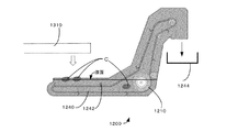
- FIG. 2A is a side sectional view schematically showing a state of the machine side tank in a conventional coolant treatment system including only the machine side tank.
- FIG. 2B is a side sectional view schematically showing a state of the drum filter and the scraper conveyor of the machine side tank shown in FIG. 2A.
- FIG. 3A is a side sectional view schematically showing a state of the machine side tank in the sludge treatment system according to the embodiment including the machine side tank and the sludge treatment device.
- FIG. 3B is a side sectional view schematically showing a state of the drum filter and the scraper conveyor of the machine side tank shown in FIG. 3A.
- the machine-side layer 200 includes a pre-filtration storage unit 220 in which the liquid sent from the machine tool 300 is stored, and a post-filtration storage unit 230 in which the liquid filtered by the drum filter 210 is stored.
- a scraper conveyor 240 is arranged in the pre-filtration storage unit 220, and the scraper 242 captures the object C to be removed such as chips carried with the liquid, and the scraper 242 transports the scraper conveyor 240 to the disposal box 244 for disposal.
- the drum filter 210 also functions as a conveyor wheel for the scraper conveyor 240.
- the filtered liquid stored in the post-filter storage unit 230 is sent to the sludge treatment device 100 by the primary tank supply pump 162.
- the conventional machine-side layer 1200 also has substantially the same configuration as the machine-side layer 200 according to the present embodiment.
- the liquid filtered by the drum filter 1210 is returned to the machine tool 1300 side as it is. Therefore, the liquid circulated for use in the machine tool 1300 basically needs to be stored in the machine side layer 1200. Therefore, as shown in FIGS. 2A and 2B, the liquid level of the liquid in the machine side layer 1200 is always high. Therefore, many regions of the outer peripheral surface of the drum filter 1210 are located below the liquid surface. Therefore, when the liquid is discharged from the backwash nozzle 1212 and the drum filter 1210 is backwashed, the removal of deposits on the filtration surface becomes insufficient in many regions immersed in the liquid, and the filtration performance deteriorates. Problems arise.
- the object C to be removed such as chips suspended near the liquid level of the liquid is located above the scraper 1242 of the scraper conveyor 1240, so that the scraper 1242 It becomes difficult to capture. Therefore, the number of objects C to be removed such as chips increases in the machine side tank 1200, and the operation becomes difficult with the passage of time.
- the liquid filtered by the drum filter 210 is sent to the sludge treatment device 100 side by the primary tank supply pump 162. That is, in the sludge treatment system 400 according to the present embodiment, the liquid circulated for use in the machine tool 300 can be stored not only in the machine side tank 200 but also in the sludge treatment device 100. Therefore, as shown in FIGS. 3A and 3B, the liquid level of the liquid can be lowered in the machine-side tank 200 according to the present embodiment.
- the amount of liquid that can be stored in the primary tank 110 and the secondary tank 120 provided in the sludge treatment device 100 is the liquid that can be stored in the machine side tank 200. Is more than the amount of. As a result, the liquid level of the liquid in the machine side tank 200 can be surely lowered.
- the liquid is filtered by the drum filter 210, but the present invention is not limited to this, and the liquid can be filtered by using any known filter or filtration device.
- the sludge treatment apparatus Next, the sludge treatment apparatus according to the present embodiment will be described with reference to FIG.
- the main body 2 for storing the liquid is partitioned by the partition portion 4, and the primary tank 110 in which the liquid flows in from the machine tool 300 side and the second tank 110 in which the liquid inside flows out to the machine tool 300 side.
- the next tank 120 is formed.
- the sludge treatment device 100 is provided with a first flow path 130 for supplying the liquid in the primary tank 110 to the secondary tank 120.
- the liquid in the machine side tank 200 is supplied to the primary tank 110 by the primary tank supply pump 162 via the primary tank supply flow path 160.
- the liquid in the primary tank 110 is supplied to the secondary tank 120 by the first flow path pump via the first flow path 130.
- the liquid in the secondary tank 120 is returned to the machine tool 300 by the return pump 172 via the return flow path 170.
- the liquid supplied from the machine side tank 200 to the primary tank 110 is filtered by the drum filter 210, but contains fine sludge and the like, and when it is returned to the machine tool 300 as it is, nozzle clogging and the like may occur. It may occur. Therefore, in the present embodiment, the filter 134 is provided on the first flow path 130 that supplies the liquid in the primary tank 110 to the secondary tank 120. In this embodiment, a cyclone filter is used as the filter 134. The filter 134 removes fine sludge contained in the liquid, and a clean liquid is supplied to the secondary tank 120. The clean liquid in the secondary tank 120 is returned to the machine tool 300 via the return flow path 170.
- the filter 134 used in the present embodiment is not limited to the cyclone filter, and any known filter capable of removing fine sludge can be adopted.
- the filter 134 arranged on the first flow path 130 removes fine sludge contained in the liquid in the primary tank 110, and supplies the filtered liquid to the secondary tank 120. can do.
- finer sludge that passes through the mesh of the filter 134 may flow into the secondary tank 120.
- the finer sludge that has passed through the filter 134 gradually aggregates in the secondary tank 120.
- the aggregated sludge accumulates in the lower part of the secondary tank 120 due to gravity. It is considered that such agglomerated sludge has a size that can be removed by the filter 134.
- a second flow path 140 different from the first flow path 130 connecting the primary tank 110 and the secondary tank 120 is used to first apply the liquid in the lower portion in the secondary tank 120. It can be returned to the next tank 110, whereby the aggregated sludge accumulated in the lower part existing in the secondary tank 120 can be returned to the primary tank.
- the aggregated sludge that has returned to the primary tank 110 is sucked into the first flow path 130 again together with the liquid, and is removed by the filter 134 in the first flow path 130. By repeating this cycle, the amount of finer sludge in the liquid can be reduced, and clogging of the nozzle or the like in the machine tool 300 can be prevented.
- the sludge treatment device 100 includes a liquid inflow amount adjusting means 142 for adjusting the inflow amount of the liquid flowing from the secondary tank 120 to the primary tank 110 through the second flow path 140.
- a liquid inflow amount adjusting means 142 an on-off valve that opens and closes the second flow path 140 by a signal from the control unit is used.
- the on-off valve (liquid inflow amount adjusting means) 142 is opened while the liquid level H2 of the secondary tank 120 is higher than the liquid level H1 of the primary tank 110, the liquid is introduced according to the so-called siphon principle. It can be returned from the secondary tank 120 to the primary tank 110.
- the aggregated sludge accumulated in the lower part of the secondary tank 120 can be reliably returned to the primary tank 110.
- the sludge treatment device 100 capable of removing fine sludge in the liquid with a simple structure can be realized.
- the liquid inflow adjusting means 142 is an on-off valve that opens and closes the second flow path 140
- the liquid level H2 of the younger brother secondary tank 120 is the liquid level of the primary tank 110.
- the on-off valve (liquid inflow amount adjusting means) 142 By opening the on-off valve (liquid inflow amount adjusting means) 142 in a state higher than H1, the aggregated sludge accumulated in the lower part of the secondary tank 120 can be reliably returned to the primary tank 110.
- the primary tank level meter S1 for detecting the liquid level H1 of the primary tank 110 and the secondary tank level meter S2 for detecting the liquid level H2 of the secondary tank 120 are used. It is equipped.
- the second flow path 140 is the lower part of the secondary tank 120. Since it is connected to, such agglomerated sludge can be efficiently returned to the primary tank 110.
- the bottom surface 8 of the secondary tank 120 is an inclined surface.
- the settled aggregated sludge tends to collect in the lower region of the inclined bottom surface 8 due to gravity.
- the inlet 140A of the second flow path 140 is arranged in the lower region of the inclined bottom surface 8
- the aggregated sludge easily flows into the first flow path 130 together with the liquid.
- the outlet 130B of the first flow path 130 to which the liquid that has passed through the filter 134 is supplied is arranged in the lower region of the inclined bottom surface 8. This facilitates the formation of aggregated sludge in the lower region of the sloping bottom surface 8.
- the bottom surface 8 of the secondary tank 120 is an inclined surface, but the present invention is not limited to this. If at least a part of the bottom surface 8 of the secondary tank 120 has a region where the level becomes lower toward the inlet 140A side of the second flow path 140, the aggregated sludge flows into the first flow path 130. It becomes easier to do. As a result, the aggregated sludge accumulated in the lower part of the secondary tank 120 can be reliably returned to the primary tank 110 via the second flow path 140.
- the second flow path 140 is connected to the lower part of the primary tank 110. Therefore, the aggregated sludge that has returned to the primary tank 110 can be effectively sucked into the first flow path 130 and removed by the filter 134.
- the inlet 130A of the first flow path 130 in the vicinity of the outlet 140B of the second flow path 140.
- the bottom surface 6 of the primary tank 110 is also an inclined surface, and the outlet 140B of the second flow path 140 is arranged in the region below the inclined bottom surface 6.
- a Y-shaped joint 144 is provided in the middle of the second flow path 140, and a second flow path liquid supply path 150 for flowing the liquid in the primary tank 110 is connected.
- the Y-shaped joint 144 is attached so as to inject the liquid from the younger brother secondary tank 120 side toward the primary tank 110 side.
- the second flow path liquid supply path 150 is branched and connected from the first flow path 130.
- the second flow path liquid supply path 150 is provided with an on-off valve 152 that opens and closes the second flow path liquid supply path 150 based on a signal from the control unit.
- the second flow path liquid supply path 150 is branched and connected from the first flow path 130, but the present invention is not limited to this.
- a separate flow path may be provided with a pump dedicated to the second flow path liquid supply path 150. Even in that case, a large ejector effect can be obtained only by using a very small pump.
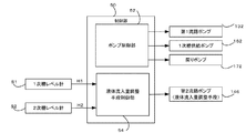
- FIG. 4 is a block diagram showing a control unit of the sludge treatment device according to one embodiment of the present disclosure.
- the control unit 50 of the sludge treatment device 100 includes a pump control unit 52 that controls the first flow path pump 132, the primary tank supply pump 162 and the return pump 172, and a liquid inflow that controls the flow rate in the second flow path 140.
- a quantity adjusting means control unit 54 is provided.
- the liquid inflow amount adjusting means control unit 54 for example, detects the liquid level H1 in the primary tank 110 of the primary tank level meter S1 and the liquid level H2 in the secondary tank 120.
- the on-off valve (liquid inflow amount adjusting means) 142 and the on-off valve 152 are controlled based on the signal received from the secondary tank level meter S2.
- FIG. 5 is a flowchart showing an example of control processing in the liquid inflow amount adjusting means control unit.
- the liquid inflow amount adjusting means control unit 54 adjusts the liquid inflow amount in the second flow path 140 based on the liquid level H1 of the primary tank 110 and the liquid level H2 of the secondary tank 120. It is designed to control the operation.
- the liquid inflow amount adjusting means control unit 54 first determines whether or not the head difference ⁇ H is larger than the first reference value D1 (step S12).
- the first reference value D1 indicates a reference head difference for determining whether or not the liquid surely flows from the secondary tank 120 to the primary tank 110 in the first flow path 130.
- step S10 If it is determined in step S10 that the head difference ⁇ H is (NO) equal to or less than the first reference value D1, this control process is terminated as it is. If it is determined in step S10 that the head difference ⁇ H is larger than the first reference value D1 (YES), the liquid inflow amount adjusting means control unit 54 sends a signal to the on-off valve (liquid inflow amount adjusting means) 142. By sending, the on-off valve (liquid inflow amount adjusting means) 142 is changed from the closed state to the open state (S12). As a result, according to the siphon principle, the liquid flows from the secondary tank 120 to the primary tank 110 in the first flow path 130.
- step S14 it is determined whether or not the head difference ⁇ H based on the signals from the level meters S1 and S2 is larger than the second reference value D2 (step S14).
- the second reference value D2 has a value larger than the first reference value D1 and indicates a reference head difference for determining whether or not flow assistance by the ejector effect is necessary. If it is determined in step S14 that the head difference ⁇ H is equal to or less than the second reference value D2 (NO), the liquid inflow amount adjusting means control unit 54 sends a signal to the on-off valve 152 to be in the closed state. To the open state (S16).
- the liquid in the primary tank 110 flows through the second flow path liquid supply path 150 and flows into the second flow path 140 from the middle of the second flow path 140.
- the flow of the liquid in the second flow path 140 is promoted based on the ejector effect.
- step S14 if it is determined in step S14 that the head difference ⁇ H is larger than the second reference value D2 (YES), that is, when the flow of the liquid in the second flow path 140 is started, the ejector effect is applied. If there is a head difference ⁇ H that allows a predetermined flow to be obtained without assistance, this determination process is repeated.
- the head difference ⁇ H between the primary tank 110 and the secondary tank 120 becomes small, and ⁇ H becomes smaller.
- the on-off valve 152 is opened to start assisting the flow of the liquid in the second flow path 140 by the ejector effect.
- the present invention is not limited to this control process, and even when the head difference ⁇ H is larger than the second reference value D2, the on-off valve 152 can be opened to add assistance by the ejector effect. In this case, the liquid in the secondary tank can be returned to the primary tank 110 more quickly.
- step S18 it is determined whether or not the head difference ⁇ H has reached 0 (step S18). When it is determined by this determination that ⁇ H has not yet reached 0 (NO), this determination process is repeated. If it is determined in step S18 that the head difference ⁇ H has reached 0 (YES), the on-off valve (liquid inflow amount adjusting means) 142 is closed (step S20), and the on-off valve 152 is closed (step S20). Step S24), this control process is terminated. As described above, the liquid inflow amount adjusting means control unit 54 determines the on-off valve (liquid inflow amount adjusting means) 142 based on the liquid level H1 of the primary tank 110 and the liquid level H2 of the secondary tank 120. Since the opening and closing of the on-off valve 152 is controlled, the aggregated sludge in the secondary tank 120 can be reliably returned to the primary tank 110.
- the liquid inflow amount adjusting means control unit 54 adjusts the liquid inflow amount in the second flow path 140 based on the liquid level H1 of the primary tank 110 and the liquid level H2 of the secondary tank 120. It is designed to control the operation, but it is not limited to this.
- the liquid inflow amount adjusting means control unit 54 adjusts the liquid inflow amount in the second flow path 140 based on the elapsed time without using the liquid level of the primary tank 110 and the secondary tank 120. It is also possible to perform control for.
- the liquid inflow amount adjusting means control unit 54 controls the opening and closing of the on-off valve (liquid inflow amount adjusting means) 142 and the on-off valve 152 based on the elapsed time.
- the primary tank supply pump 162 and the return pump 172 based on the signal from the pump control unit 52, it is based on the elapsed time.
- a plurality of control patterns based on the elapsed time are provided according to the operation patterns of the first flow path pump 132, the primary tank supply pump 162 and the return pump 172, and the optimum control pattern is selected according to the situation. You can also do it.
- the liquid inflow amount adjusting means control unit 54 controls for adjusting the liquid inflow amount in the second flow path 140 based on the elapsed time, so that no special sensor or the like is required.
- the aggregated sludge in the secondary tank 120 can be returned to the primary tank 110 with simple control.
- the flow rate of the liquid flowing in the first flow path 130 in the sludge treatment device 100 is machined from the inside of the secondary tank 120 by the return flow path 170. It is conceivable that the flow rate of the liquid flowing to the machine 300 side will be larger than the flow rate. In this way, when the amount of liquid supplied to the secondary tank 120 via the first flow path 130 is larger than the amount of liquid flowing from the inside of the secondary tank 120 to the machine tool 300 side, the secondary tank The level of 120 liquids will rise.
- the liquid in the secondary tank 120 can be returned to the primary tank 110 side by using the second flow path 140 to lower the liquid level of the liquid in the secondary tank 120. it can. As a result, substantially the same effect as increasing the volume of the liquid in the secondary tank 120 can be obtained, and the sludge treatment device 100 can be downsized.
- FIG. 6 is a diagram schematically showing a sludge treatment system according to another embodiment of the present disclosure.
- FIG. 7 is a block diagram showing a control unit of the sludge treatment device according to another embodiment of the present disclosure.
- the on-off valve 142 is provided as the liquid inflow adjusting means, and the flow of the second flow path 140 is formed by using the siphon principle.
- the second flow path pump 146 is provided as the liquid inflow amount adjusting means, and the flow of the second flow path 140 is formed by the discharge force of the second flow path pump (liquid inflow amount adjusting means) 146. It differs in that it is.
- the liquid flows from the secondary tank 120 to the primary tank 110 in the second flow path 140 by the second flow path pump (liquid inflow amount adjusting means) 146.
- the inlet (suction port) 140A of the second flow path 140 is arranged in the lower part of the secondary tank 120 in which aggregated sludge tends to accumulate.
- the liquid level H2 of the secondary tank 120 is higher than the liquid level H1 of the primary tank 110. Even in the absence state, the liquid can flow from the secondary tank 120 to the primary tank 110. Further, in the present embodiment, it is not necessary to provide the second flow path liquid supply path 150 that promotes the flow by the ejector effect.
- the liquid inflow amount adjusting means control unit 54 controls the drive of the second flow path pump (liquid inflow amount adjusting means) 146 instead of the on-off valve (liquid inflow amount adjusting means) 142 and the on-off valve 152. It is designed to do. As a result, the aggregated sludge in the secondary tank 120 can be returned to the primary tank 110 while adjusting the liquid level levels of the primary tank 110 and the secondary tank 120.
- the primary tank 110 and the secondary tank 120 are formed by partitioning the main body 2 by the partition portion 4, but the present invention is not limited to this.
- the primary tank and the secondary tank may be separate members each having a separate main body. In that case, by setting the installation position of the secondary tank higher than the installation position of the primary tank, it is possible to easily obtain the flow of the liquid in the second flow path according to the siphon principle.
Landscapes
- Chemical & Material Sciences (AREA)
- Chemical Kinetics & Catalysis (AREA)
- Engineering & Computer Science (AREA)
- Mechanical Engineering (AREA)
- Life Sciences & Earth Sciences (AREA)
- Hydrology & Water Resources (AREA)
- Environmental & Geological Engineering (AREA)
- Water Supply & Treatment (AREA)
- Organic Chemistry (AREA)
- Treatment Of Sludge (AREA)
- Filtration Of Liquid (AREA)
- Auxiliary Devices For Machine Tools (AREA)
Abstract
シンプルな構造で液中の微細なスラッジを除去可能なように、工作機械300側から液体が流入する第1次槽110と、内部の液体が工作機械300側へ流出する第2次槽120と、第1次槽110内の液体を第2次槽120へ供給する第1流路130と、第1流路130上に配置されたフィルタ134と、第1次槽110及び第2次槽120を繋ぐ第1流路130とは異なる第2流路140と、第2流路140内を通じて第2次槽120から第1次槽110へ流入する液体流入量を調整する液体流入量調整手段142と、を備え、 第2流路140の途中から、第1次槽110内の液体を第2次槽120側から第1次槽110側へ向けて流入させる第2流路液体供給路150を備えるスラッジ処理装置100及びスラッジ処理システム400を提供する。
Description
本開示は、工作機械で使用されたクーラントに含まれるスラッジの処理装置及びそのスラッジ処理装置を備えたスラッジ処理システムに関する。
工作機械では、ワーク及び工具の間の潤滑や冷却のためにクーラント(切削液) が使用される。工作機械から排出されたクーラントには、 切屑や微粒子等の除去対象物が混入している。これを除去するため、クーラント中の切り粉を掻き上げるスクレーパコンベア及びクーラントを濾過するドラムフィルタを備えた処理装置が広く用いられている。その中には、複数のドラムフィルタを備えて、濾過能力を高めたものが提案されている(例えば、特許文献1参照)。
しかしながら、特許文献1の記載の処理装置のように、ドラムフィルタを用いた濾過だけでは、その濾過能力にはおのずと限界があり、微細なスラッジを除去することは困難である。よって、微細なスラッジが含まれるクーラントを工作機械側に戻して再使用すると、ノズル詰まり等の問題が生じる可能性がある。一方、微細なスラッジを除去するために複雑で大型な廃液処理設備を備える場合には、設備コストやランニングコストが増大する。
本開示は、シンプルな構造で液中の微細なスラッジを除去可能なスラッジ処理装置及びスラッジ処理システムを提供することを目的とする。
上記課題を解決するために、本開示の1つの実施態様に係るスラッジ処理装置は、
工作機械側から液体が流入する第1次槽と、
内部の液体が工作機械側へ流出する第2次槽と、
前記第1次槽内の液体を前記第2次槽へ供給する第1流路と、
前記第1流路上に配置されたフィルタと、
前記第1次槽及び前記第2次槽を繋ぐ前記第1流路とは異なる第2流路と、
前記第2流路内を通じて前記第2次槽から前記第1次槽へ流入する液体流入量を調整する液体流入量調整手段と、を備える。
工作機械側から液体が流入する第1次槽と、
内部の液体が工作機械側へ流出する第2次槽と、
前記第1次槽内の液体を前記第2次槽へ供給する第1流路と、
前記第1流路上に配置されたフィルタと、
前記第1次槽及び前記第2次槽を繋ぐ前記第1流路とは異なる第2流路と、
前記第2流路内を通じて前記第2次槽から前記第1次槽へ流入する液体流入量を調整する液体流入量調整手段と、を備える。
本開示の1つの実施態様に係るスラッジシステムは、
上記のスラッジ処理装置と、
工作機械側に設置された機側槽と、
前記機側槽内に配置されたドラムフィルタと、
前記ドラムフィルタを通過した前記機側槽内の液体を前記第1次槽へ供給する1次槽供給ポンプと、
を備える。
上記のスラッジ処理装置と、
工作機械側に設置された機側槽と、
前記機側槽内に配置されたドラムフィルタと、
前記ドラムフィルタを通過した前記機側槽内の液体を前記第1次槽へ供給する1次槽供給ポンプと、
を備える。
上記の実施態様によれば、シンプルな構造で液中の微細なスラッジを除去可能なスラッジ処理装置及びスラッジ処理システムを提供することができる。
以下、図面を参照しながら、本開示を実施するための実施形態を説明する。なお、以下に説明する実施形態は、本開示の技術思想を具体化するためのものであって、特定的な記載がない限り、本開示を以下のものに限定しない。
各図面中、同一の機能を有する部材には、同一符号を付している場合がある。要点の説明または理解の容易性を考慮して、便宜上実施形態を分けて示す場合があるが、異なる実施形態で示した構成の部分的な置換または組み合わせは可能である。後述の実施形態では前述の実施形態と共通の事柄についての記述を省略し、異なる点についてのみ説明する。特に、同様の構成による同様の作用効果については、実施形態ごとには逐次言及しないものとする。各図面が示す部材の大きさや位置関係等は、説明を明確にするため、誇張して示している場合もある。
図面中、流路の中を流れる液体の流れを矢印で示してある。
各図面中、同一の機能を有する部材には、同一符号を付している場合がある。要点の説明または理解の容易性を考慮して、便宜上実施形態を分けて示す場合があるが、異なる実施形態で示した構成の部分的な置換または組み合わせは可能である。後述の実施形態では前述の実施形態と共通の事柄についての記述を省略し、異なる点についてのみ説明する。特に、同様の構成による同様の作用効果については、実施形態ごとには逐次言及しないものとする。各図面が示す部材の大きさや位置関係等は、説明を明確にするため、誇張して示している場合もある。
図面中、流路の中を流れる液体の流れを矢印で示してある。
(スラッジ処理システム)
はじめに、図1を参照しながら、本開示の1つの実施形態に係るスラッジ処理システムの説明を行う。図1は、本開示の1つの実施形態に係るスラッジ処理システムを模式的に示す線図である。本実施形態に係るスラッジ処理システム400は、機側槽200及びスラッジ処理装置100を備える。
はじめに、図1を参照しながら、本開示の1つの実施形態に係るスラッジ処理システムの説明を行う。図1は、本開示の1つの実施形態に係るスラッジ処理システムを模式的に示す線図である。本実施形態に係るスラッジ処理システム400は、機側槽200及びスラッジ処理装置100を備える。
工作機械300における切削加工や研削加工で用いられたクーラントは、切屑とともに、コンベア310を介して機側槽200に流入する。機側槽200では、切屑を含むクーラントを一時的に貯留して、ドラムフィルタ210により濾過を行って、濾過されたクーラントを、1次槽供給ポンプ162を用いて、スラッジ処理装置100へ送る。
スラッジ処理装置100では、機側槽200から送られたクーラントに含まれるスラッジを除去する処理を行って、処理されたクーラントを工作機械300に戻す。工作機械300に戻されたクーラントは、再び、切削加工に用いられ、このような循環サイクルを繰り返す。なお、以下の記載においては、機側槽200やスラッジ処理装置100を流れるクーラントを液体と称する。
スラッジ処理装置100では、機側槽200から送られたクーラントに含まれるスラッジを除去する処理を行って、処理されたクーラントを工作機械300に戻す。工作機械300に戻されたクーラントは、再び、切削加工に用いられ、このような循環サイクルを繰り返す。なお、以下の記載においては、機側槽200やスラッジ処理装置100を流れるクーラントを液体と称する。
(機側槽)
次に、図1に加えて、図2A、図2B、図3A及び図3Bを参照して、従来例と比較しながら、1つの実施形態に係る機側層200の説明を行う。図2Aは、機側槽のみを備える従来のクーラント処理システムにおける機側槽の状態を模式的に示す側面断面図である。図2Bは、図2Aに示す機側槽のドラムフィルタ及びスクレーパコンベアの状態を模式的に示す側面断面図である。図3Aは、機側槽及びスラッジ処理装置を備える1つの実施形態に係るスラッジ処理システムにおける機側槽の状態を模式的に示す側面断面図である。図3Bは、図3Aに示す機側槽のドラムフィルタ及びスクレーパコンベアの状態を模式的に示す側面断面図である。
次に、図1に加えて、図2A、図2B、図3A及び図3Bを参照して、従来例と比較しながら、1つの実施形態に係る機側層200の説明を行う。図2Aは、機側槽のみを備える従来のクーラント処理システムにおける機側槽の状態を模式的に示す側面断面図である。図2Bは、図2Aに示す機側槽のドラムフィルタ及びスクレーパコンベアの状態を模式的に示す側面断面図である。図3Aは、機側槽及びスラッジ処理装置を備える1つの実施形態に係るスラッジ処理システムにおける機側槽の状態を模式的に示す側面断面図である。図3Bは、図3Aに示す機側槽のドラムフィルタ及びスクレーパコンベアの状態を模式的に示す側面断面図である。
本実施形態に係る機側層200は、工作機械300から送られた液体が蓄えられる濾過前貯蔵部220と、ドラムフィルタ210で濾過された液体が蓄えられる濾過後貯蔵部230とを備える。濾過前貯蔵部220には、スクレーパコンベア240が配置されており、液体とともに運ばれてきた切屑等の除去対象物Cを、スクレーパ242で捕獲して、コンベアで廃棄ボックス244まで運んで廃棄する。ドラムフィルタ210は、スクレーパコンベア240のコンベアホイールの機能も果たしている。濾過後貯蔵部230で蓄えられる濾過後の液体は、1次槽供給ポンプ162により、スラッジ処理装置100へ送られる。
従来の機側層1200も、本実施形態に係る機側層200とほぼ同様な構成を有する。しかし、従来の機側層1200では、ドラムフィルタ1210で濾過された液体を、そのまま工作機械1300側に戻すようになっている。よって、工作機械1300で用いるために循環される液体は、基本的に機側層1200で蓄える必要がある。よって、図2A、図2Bに示すように、機側層1200における液体の液面レベルが常に高くなっている。
従って、ドラムフィルタ1210の外周面の多くの領域が液面より下に位置することになる。このため、逆洗用ノズル1212から液体を放出してドラムフィルタ1210の逆洗を行うとき、液体に浸かった多くの領域において、濾過面の付着物の除去が不十分になり、濾過性能が低下する問題が生じる。
従って、ドラムフィルタ1210の外周面の多くの領域が液面より下に位置することになる。このため、逆洗用ノズル1212から液体を放出してドラムフィルタ1210の逆洗を行うとき、液体に浸かった多くの領域において、濾過面の付着物の除去が不十分になり、濾過性能が低下する問題が生じる。
更に、機側槽1200内の液面レベルが高いので、液体の液面近傍に浮遊した切り粉等の除去対象物Cが、スクレーパコンベア1240のスクレーパ1242よりも上方に位置するため、スクレーパ1242で捕獲することが困難になる。よって、機側槽1200内に切り粉等の除去対象物Cが増えて、時間の経過とともに稼働が困難となる。
一方、本実施形態に係る機側槽200では、ドラムフィルタ210で濾過された液体は、1次槽供給ポンプ162によりスラッジ処理装置100側へ送られる。つまり、本実施形態に係るスラッジ処理システム400では、工作機械300で用いるために循環される液体を、機側槽200内だけでなく、スラッジ処理装置100内でも蓄えることができる。よって、図3A、図3Bに示すように、本実施形態に係る機側槽200では、液体の液面レベルを下げることができる。
これにより、ドラムフィルタ210の外周面のより多くの領域を、液体の液面より上に位置させることができる。よって、逆洗用ノズル212から液体を放出してドラムフィルタ210の逆洗を行ったときに、逆洗のための液体の多くを濾過面から大気中に流出させることができるので、濾過面の付着物をより効果的に除去できる。これにより、濾過性能が低下することを抑制できる。
更に、機側槽200内のクーラントの液面レベルが低いので、液体の液面近傍に浮遊した切屑等の除去対象物Cを、スクレーパコンベア240のスクレーパ242で捕獲することができる。これにより、液体とともに機側槽200に入ってきた切屑等の除去対象物Cを、十分に除去することができる。
更に、機側槽200内のクーラントの液面レベルが低いので、液体の液面近傍に浮遊した切屑等の除去対象物Cを、スクレーパコンベア240のスクレーパ242で捕獲することができる。これにより、液体とともに機側槽200に入ってきた切屑等の除去対象物Cを、十分に除去することができる。
特に、本実施形態に係るスラッジ処理システム400では、スラッジ処理装置100に設けられた第1次槽110及び第2次槽120で貯蔵可能な液体の量が、機側槽200で貯蔵可能な液体の量より多くなっている。これにより、確実に機側槽200内の液体の液面レベルを下げることができる。
なお、本実施形態では、ドラムフィルタ210により液体の濾過を行っているが、これに限られるものではなく、既知の任意のフィルタ、濾過装置を用いて、液体を濾過することができる。
なお、本実施形態では、ドラムフィルタ210により液体の濾過を行っているが、これに限られるものではなく、既知の任意のフィルタ、濾過装置を用いて、液体を濾過することができる。
(1つの実施形態に係るスラッジ処理装置)
次に、図1を参照しながら、1つの本実施形態に係るスラッジ処理装置の説明を行う。スラッジ処理装置100は、液体を貯蔵する本体2が仕切り部4で仕切られて、工作機械300側から液体が流入する第1次槽110と、内部の液体が工作機械300側へ流出する第2次槽120とが形成されている。更に、スラッジ処理装置100には、第1次槽110内の液体を第2次槽120へ供給する第1流路130を備えられている。
次に、図1を参照しながら、1つの本実施形態に係るスラッジ処理装置の説明を行う。スラッジ処理装置100は、液体を貯蔵する本体2が仕切り部4で仕切られて、工作機械300側から液体が流入する第1次槽110と、内部の液体が工作機械300側へ流出する第2次槽120とが形成されている。更に、スラッジ処理装置100には、第1次槽110内の液体を第2次槽120へ供給する第1流路130を備えられている。
更に詳細に述べれば、機側槽200内の液体は、1次槽供給ポンプ162により、1次槽供給流路160を介して第1次槽110へ供給される。第1次槽110内の液体は、第1流路ポンプにより、第1流路130を介して第2次槽120へ供給される。第2次槽120内の液体は、戻りポンプ172により、戻り流路170を介して工作機械300へ戻される。
機側槽200から第1次槽110へ供給された液体は、ドラムフィルタ210で濾過はされているが、微細なスラッジ等が含まれており、そのまま工作機械300へ戻すと、ノズル詰まり等が生じる虞がある。そこで、本実施形態では、第1次槽110の液体を第2次槽120へ供給する第1流路130上にフィルタ134が備えられている。本実施形態では、フィルタ134としてサイクロンフィルタが用いられている。フィルタ134により、液体に含まれる微細なスラッジが除去されて、クリーンな液体が第2次槽120へ供給される。この第2次槽120内のクリーンな液体が、戻り流路170を介して工作機械300へ戻される。
なお、本実施形態で用いるフィルタ134として、サイクロンフィルタに限られるものではなく、微細なスラッジを除去可能な既知の任意のフィルタを採用することができる。
なお、本実施形態で用いるフィルタ134として、サイクロンフィルタに限られるものではなく、微細なスラッジを除去可能な既知の任意のフィルタを採用することができる。
上記のように、第1流路130上に配置されたフィルタ134により、第1次槽110内の液体に含まれる微細なスラッジを除去して、濾過済みの液体を第2次槽120へ供給することができる。しかし、フィルタ134のメッシュを透過する更に微細なスラッジが、第2次槽120へ流入する可能性がある。そのような液体が、第2次槽120から工作機械300側へ流出した場合、工作機械300のノズル等を詰まらせる可能性を否定できない。
このとき、フィルタ134を透過した更に微細なスラッジは、第2次槽120内で徐々に凝集すると考えられる。そして、凝集スラッジは、重力により第2次槽120の下部に溜まると考えられる。このような凝集スラッジは、フィルタ134で除去可能な大きさになっていると考えられる。
このとき、フィルタ134を透過した更に微細なスラッジは、第2次槽120内で徐々に凝集すると考えられる。そして、凝集スラッジは、重力により第2次槽120の下部に溜まると考えられる。このような凝集スラッジは、フィルタ134で除去可能な大きさになっていると考えられる。
そこで、本実施形態では、第1次槽110及び第2次槽120を繋ぐ第1流路130とは異なる第2流路140を用いて、第2次槽120内の下部の液体を第1次槽110に戻すことができる、これにより、第2次槽120内に存在する下部に溜まった凝集スラッジを、第1次槽に戻すことができる。第1次槽110に戻った凝集スラッジは、液体とともに、再び第1流路130に吸引され、第1流路130中のフィルタ134で除去される。このサイクルを繰り返すことにより、液体中の更に微細なスラッジの量を減らして、工作機械300におけるノズル等の詰まりを防ぐことができる。
本実施形態に係るスラッジ処理装置100は、第2流路140内を通じて第2次槽120から第1次槽110へ流入する液体の流入量を調整する液体流入量調整手段142を備えている。ここでは、液体流入量調整手段142として、制御部からの信号により第2流路140を開閉する開閉弁が用いられている。第2次槽120の液面レベルH2が第1次槽110の液面レベルH1より高い状態で、開閉弁(液体流入量調整手段)142を開にすると、所謂サイフォンの原理により、液体を第2次槽120から第1次槽110へ戻すことができる。これにより、第2次槽120内の下部に溜まった凝集スラッジを確実に第1次槽110に戻すことができる。
以上のようにして、シンプルな構造で液中の微細なスラッジを除去可能なスラッジ処理装置100を実現できる。
以上のようにして、シンプルな構造で液中の微細なスラッジを除去可能なスラッジ処理装置100を実現できる。
上記のように、液体流入量調整手段142が、第2流路140の開閉を行う開閉弁である場合には、弟2次槽120の液面レベルH2が第1次槽110の液面レベルH1より高い状態で、開閉弁(液体流入量調整手段)142を開にすることにより、第2次槽120内の下部に溜まった凝集スラッジを確実に第1次槽110に戻すことができる。
なお、本実施形態では、第1次槽110の液面レベルH1を検出する第1次槽レベル計S1、及び第2次槽120の液面レベルH2を検出する第2次槽レベル計S2が備えられている。
なお、本実施形態では、第1次槽110の液面レベルH1を検出する第1次槽レベル計S1、及び第2次槽120の液面レベルH2を検出する第2次槽レベル計S2が備えられている。
第2次槽120内に存在する凝集スラッジの多くは、第2次槽120の下部に溜まっていることが考えられるが、本実施形態では、第2流路140が第2次槽120の下部に繋がっているので、そのような凝集スラッジを効率的に第1次槽110へ戻すことができる。
更に、本実施形態では、第2次槽120の底面8が傾斜面になっている。これにより、沈殿した凝集スラッジは、重力により、傾斜した底面8の下側の領域に集まり易くなる。本実施形態では、第2流路140の入口140Aが、傾斜した底面8の下側の領域に配置されているので、凝集スラッジが液体とともに第1流路130に流入し易くなっている。
更に、フィルタ134を通過した液体が供給される第1流路130の出口130Bが、傾斜した底面8の下側の領域に配置されている。これにより、凝集スラッジが、傾斜した底面8の下側の領域に形成され易くなっている。
更に、フィルタ134を通過した液体が供給される第1流路130の出口130Bが、傾斜した底面8の下側の領域に配置されている。これにより、凝集スラッジが、傾斜した底面8の下側の領域に形成され易くなっている。
本実施形態では、第2次槽120の底面8が傾斜面になっているが、これに限られるものではない。第2次槽120の底面8の少なくとも一部に、第2流路140の入口140A側に向けてレベルが低くなる領域を有するようになっていれば、凝集スラッジが第1流路130に流入し易くなる。これにより、確実に第2次槽120内の下部に溜まった凝集スラッジを、第2流路140を介して第1次槽110に戻すことができる。
図1から明らかなように、本実施形態では、第2流路140が第1次槽110の下部に繋がっている。よって、第1次槽110に戻った凝集スラッジを効果的に第1流路130に吸い込んで、フィルタ134で除去することができる。特に、第1流路130の入口130Aを、第2流路140の出口140Bの近傍に配置するのが好ましい。
更に、第1次槽110の底面6も傾斜面になっており、傾斜した底面6の下側の領域に、第2流路140の出口140Bが配置されている。
更に、第1次槽110の底面6も傾斜面になっており、傾斜した底面6の下側の領域に、第2流路140の出口140Bが配置されている。
更に、本実施形態では、第2流路140の途中にY字継ぎ手144が設けられており、第1次槽110内の液体を流入させる第2流路液体供給路150が接続されている。Y字継ぎ手144は、液体を弟2次槽120側から第1次槽110側へ向けて注入するように傾斜して取り付けられている。本実施形態では、第2流路液体供給路150は、第1流路130から分岐して接続されている。第2流路液体供給路150には、制御部からの信号に基づいて、第2流路液体供給路150を開閉する開閉弁152が設けられている。
開閉弁152が開になると、第1流路ポンプ132で吐出された第1次槽110内の液体の一部が、第2流路液体供給路150を流れて、第2流路140の途中から、第2次槽120側から第1次槽110側へ向けて流入するようになっている。
開閉弁152が開になると、第1流路ポンプ132で吐出された第1次槽110内の液体の一部が、第2流路液体供給路150を流れて、第2流路140の途中から、第2次槽120側から第1次槽110側へ向けて流入するようになっている。
これにより、所謂エジェクタ効果が生じて、第2流路140内における第2次槽120側から第1次槽110側への流れを促進させることができる。これにより、より効果的に第2次槽120内の下部に溜まった凝集スラッジを、第1次槽110に戻すことができる。
特に、第1次槽110における液面レベルH1及び第2次槽120における液面レベルH2のレベル差が小さくて、サイフォンの原理による第2流路140内の流れが弱い場合に、第2流路液体供給路150によるエジェクタ効果を付与することにより、第2流路140内の流れを促進できる。これらに関する制御処理については、追って詳細に述べる。
特に、第1次槽110における液面レベルH1及び第2次槽120における液面レベルH2のレベル差が小さくて、サイフォンの原理による第2流路140内の流れが弱い場合に、第2流路液体供給路150によるエジェクタ効果を付与することにより、第2流路140内の流れを促進できる。これらに関する制御処理については、追って詳細に述べる。
本実施形態では、第2流路液体供給路150が第1流路130から分岐して接続されているが、これに限られるものではない。第2流路液体供給路150専用のポンプを備えた個別の流路を備えることもできる。その場合であっても、非常に小型なポンプを用いるだけで、大きなエジェクタ効果を得ることができる。
(制御部)
次に、図4を参照しながら、1つの実施形態に係るスラッジ処理装置の制御部の説明を行う。図4は、本開示の1つの実施形態に係るスラッジ処理装置の制御部を示すブロック図である。スラッジ処理装置100の制御部50は、第1流路ポンプ132、1次槽供給ポンプ162及び戻りポンプ172の制御を行うポンプ制御部52と、第2流路140における流量の制御を行う液体流入量調整手段制御部54とを備える。
液体流入量調整手段制御部54は、例えば、第1次槽110内の液面レベルH1を検出する第1次槽レベル計S1、及び第2次槽120内の液面レベルH2を検出する第2次槽レベル計S2から受信した信号に基づいて、開閉弁(液体流入量調整手段)142や開閉弁152の制御を行う。
(流入量調整処理の一例)
次に、図5を参照しながら、液体流入量調整手段制御部54による制御処理の一例を説明する。図5は、液体流入量調整手段制御部における制御処理の一例を示すフローチャートである。本フローチャートでは、液体流入量調整手段制御部54が、第1次槽110の液面レベルH1及び第2次槽120の液面レベルH2に基づいて、第2流路140における液体流入量を調整するための制御を行うようになっている。
次に、図5を参照しながら、液体流入量調整手段制御部54による制御処理の一例を説明する。図5は、液体流入量調整手段制御部における制御処理の一例を示すフローチャートである。本フローチャートでは、液体流入量調整手段制御部54が、第1次槽110の液面レベルH1及び第2次槽120の液面レベルH2に基づいて、第2流路140における液体流入量を調整するための制御を行うようになっている。
液体流入量調整手段制御部54は、常時、第1次槽レベル計S1から、第1次槽110の液面レベルH1に関する信号を受け、第2次槽レベル計S2から、第2次槽120の液面レベルH2に関する信号を受けている。そして、受信した信号に基づいて、常に、液面レベルの差分であるΔH=H2-H1を算出している。算出されたΔHの値は、第1次槽110及び第2次槽120の液面レベルの変動によって逐次変化している。
液体流入量調整手段制御部54は、まず、ヘッド差ΔHが第1基準値D1より大きいか否か判断する(ステップS12)。ここで、第1基準値D1は、液体が第1流路130の中を第2次槽120から第1次槽110へ確実に流れるか否かを判断する基準のヘッド差を示す。
液体流入量調整手段制御部54は、まず、ヘッド差ΔHが第1基準値D1より大きいか否か判断する(ステップS12)。ここで、第1基準値D1は、液体が第1流路130の中を第2次槽120から第1次槽110へ確実に流れるか否かを判断する基準のヘッド差を示す。
ステップS10の判断で、もし、ヘッド差ΔHが第1基準値D1以下である(NO)と判別したときには、そのままこの制御処理を終了する。ステップS10の判断で、もし、ヘッド差ΔHが第1基準値D1より大きい(YES)と判別したときには、液体流入量調整手段制御部54は、開閉弁(液体流入量調整手段)142へ信号を送って、開閉弁(液体流入量調整手段)142を閉の状態から開の状態へ変更する(S12)。これにより、サイフォンの原理により、液体が第1流路130の中を第2次槽120から第1次槽110へ流れるようになる。
次に、レベル計S1、S2からの信号に基づくヘッド差ΔHが、第2基準値D2より大きいか否か判断する(ステップS14)。ここで、第2基準値D2は、第1基準値D1より大きな値を有し、エジェクタ効果による流れの補助が必要か否かを判断する基準のヘッド差を示す。
ステップS14の判断で、もし、ヘッド差ΔHが第2基準値D2以下である(NO)と判別したときには、液体流入量調整手段制御部54は、開閉弁152へ信号を送って、閉の状態から開の状態へ変更する(S16)。これにより、第1次槽110内の液体が、第2流路液体供給路150内を流れて、第2流路140の途中から第2流路140内に流入する。これにより、エジェクタ効果に基づき、第2流路140内の液体の流れが促進される。
ステップS14の判断で、もし、ヘッド差ΔHが第2基準値D2以下である(NO)と判別したときには、液体流入量調整手段制御部54は、開閉弁152へ信号を送って、閉の状態から開の状態へ変更する(S16)。これにより、第1次槽110内の液体が、第2流路液体供給路150内を流れて、第2流路140の途中から第2流路140内に流入する。これにより、エジェクタ効果に基づき、第2流路140内の液体の流れが促進される。
つまり、開閉弁(液体流入量調整手段)142を開にして、第2流路140内の液体の流れを開始した時点で、ヘッド差ΔHがさほど大きくなく、エジェクタ効果による流れの補助を要する場合には、流れの開始当初から開閉弁152を開にする。
一方、ステップS14の判断で、もし、ヘッド差ΔHが第2基準値D2より大きい(YES)と判別したとき、つまり、第2流路140内の液体の流れを開始した時点で、エジェクタ効果による補助がなくても所定の流れが得られるヘッド差ΔHがある場合には、この判断処理を繰り返す。そして、液体が第1流路130の中を第2次槽120から第1次槽110へ流れることにより、第1次槽110及び第2次槽120のヘッド差ΔHが小さくなって、ΔHが第2基準値D2以下となると、開閉弁152を開にして、エジェクタ効果による、第2流路140内の液体の流れの補助を開始する。
ただし、この制御処理に限られるものではなく、ヘッド差ΔHが第2基準値D2より大きい場合であっても、開閉弁152を開にして、エジェクタ効果による補助を加えることもできる。この場合には、より速やかに、第2次槽内の液体を第1次槽110へ戻すことができる。
次に、ヘッド差ΔHが0に達したか否か判断する(ステップS18)。この判断で、まだΔHが0に達していない(NO)と判別したときには、この判断処理を繰り返す。ステップS18の判断で、もし、ヘッド差ΔHが0に達した(YES)と判別したときには、開閉弁(液体流入量調整手段)142を閉にし(ステップS20)、開閉弁152を閉にして(ステップS24)、この制御処理を終了する。
以上のように、液体流入量調整手段制御部54が、第1次槽110の液面レベルH1及び第2次槽120の液面レベルH2に基づいて、開閉弁(液体流入量調整手段)142や開閉弁152の開閉の制御を行うので、確実に第2次槽120内の凝集スラッジを第1次槽110に戻すことができる。
以上のように、液体流入量調整手段制御部54が、第1次槽110の液面レベルH1及び第2次槽120の液面レベルH2に基づいて、開閉弁(液体流入量調整手段)142や開閉弁152の開閉の制御を行うので、確実に第2次槽120内の凝集スラッジを第1次槽110に戻すことができる。
(流入量調整処理のその他の例)
上記の例では、液体流入量調整手段制御部54が第1次槽110の液面レベルH1及び第2次槽120の液面レベルH2に基づいて、第2流路140における液体流入量を調整するための制御を行うようになっているが、これに限られるものではない。
スラッジ処理装置100において、液体を循環させて定常状態に入れば、ある一定の時間間隔で第1次槽110及び第2次槽120の液面レベルが推移すると考えられる。よって、液体流入量調整手段制御部54が、第1次槽110及び第2次槽120の液面レベルを用いることなく、経過時間に基づいて、第2流路140における液体流入量を調整するための制御を行うこともできる。
上記の例では、液体流入量調整手段制御部54が第1次槽110の液面レベルH1及び第2次槽120の液面レベルH2に基づいて、第2流路140における液体流入量を調整するための制御を行うようになっているが、これに限られるものではない。
スラッジ処理装置100において、液体を循環させて定常状態に入れば、ある一定の時間間隔で第1次槽110及び第2次槽120の液面レベルが推移すると考えられる。よって、液体流入量調整手段制御部54が、第1次槽110及び第2次槽120の液面レベルを用いることなく、経過時間に基づいて、第2流路140における液体流入量を調整するための制御を行うこともできる。
つまり、液体流入量調整手段制御部54が、経過時間に基づいて、開閉弁(液体流入量調整手段)142及び開閉弁152の開閉の制御を行う。このとき、ポンプ制御部52からの信号に基づいて、第1流路ポンプ132、1次槽供給ポンプ162及び戻りポンプ172で定常の運転が行われていると判別したときに、経過時間に基づく制御を行う。更に、第1流路ポンプ132、1次槽供給ポンプ162及び戻りポンプ172の稼働パターンに応じて、経過時間に基づく複数の制御パターンを備えていて、状況に応じて最適な制御パターンを選択することもできる。
以上のように、液体流入量調整手段制御部54が、経過時間に基づいて、第2流路140における液体流入量を調整するための制御を行うことにより、特別なセンサ等を要さずに、シンプルな制御で第2次槽120内の凝集スラッジを第1次槽110に戻すことができる。
(第2流路のその他の効果)
工作機械300における切削加工の状況に基づく液体の循環を考えると、スラッジ処理装置100において、第1流路130内を流れる液体の流量が、戻り流路170により、第2次槽120内から工作機械300側へ流れる液体の流量より多くなることが考えられる。このように、第1流路130を介して第2次槽120に供給される液体の量が、第2次槽120内から工作機械300側へ流れる液体の量より多い場合、第2次槽120の液体のレベルが上昇することになる。このため、多くの液体を循環させる場合、第2次槽120の容量を大きくする必要があり、スラッジ処理装置100の小型化が困難になる。しかし、本実施形態では、第2流路140を用いて、第2次槽120内の液体を第1次槽110側へ戻して、第2次槽120の液体の液面レベルを下げることができる。これにより、実質的に第2次槽120における液体の容量を増やしたことと同じ効果が得られ、スラッジ処理装置100の小型化が図れる。
工作機械300における切削加工の状況に基づく液体の循環を考えると、スラッジ処理装置100において、第1流路130内を流れる液体の流量が、戻り流路170により、第2次槽120内から工作機械300側へ流れる液体の流量より多くなることが考えられる。このように、第1流路130を介して第2次槽120に供給される液体の量が、第2次槽120内から工作機械300側へ流れる液体の量より多い場合、第2次槽120の液体のレベルが上昇することになる。このため、多くの液体を循環させる場合、第2次槽120の容量を大きくする必要があり、スラッジ処理装置100の小型化が困難になる。しかし、本実施形態では、第2流路140を用いて、第2次槽120内の液体を第1次槽110側へ戻して、第2次槽120の液体の液面レベルを下げることができる。これにより、実質的に第2次槽120における液体の容量を増やしたことと同じ効果が得られ、スラッジ処理装置100の小型化が図れる。
(その他の実施形態に係るスラッジ処理装置)
次に、図6から図8を参照しながら、本開示のその他の本実施形態に係るスラッジ処理装置の説明を行う。図6は、本開示のその他の実施形態に係るスラッジ処理システムを模式的に示す線図である。図7は、本開示のその他の実施形態に係るスラッジ処理装置の制御部を示すブロック図である。
次に、図6から図8を参照しながら、本開示のその他の本実施形態に係るスラッジ処理装置の説明を行う。図6は、本開示のその他の実施形態に係るスラッジ処理システムを模式的に示す線図である。図7は、本開示のその他の実施形態に係るスラッジ処理装置の制御部を示すブロック図である。
上記の本実施形態では、液体流入量調整手段として開閉弁142を備え、サイフォンの原理を用いて第2流路140の流れを形成していた。一方、本実施形態では、液体流入量調整手段として第2流路ポンプ146を備え、第2流路ポンプ(液体流入量調整手段)146の吐出力によって、第2流路140の流れを形成するようになっている点で異なる。第2流路ポンプ(液体流入量調整手段)146により、液体が第2流路140の中を第2次槽120から第1次槽110へ流れるようになっている。このとき、第2流路140の入口(ポンプの吸込口)140Aは、凝集スラッジがたまり易い第2次槽120の下部に配置されている。
本実施形態では、第2流路ポンプ(液体流入量調整手段)146の吐出力によって液体を流すので、第2次槽120の液面レベルH2が第1次槽110の液面レベルH1より高くない状態でも、液体を第2次槽120から第1次槽110へ流すことができる。また、本実施形態では、エジェクタ効果で流れを促進する第2流路液体供給路150を備える必要はない。
本実施形態に係る液体流入量調整手段制御部54では、開閉弁(液体流入量調整手段)142及び開閉弁152の代わりに、第2流路ポンプ(液体流入量調整手段)146の駆動を制御するようになっている。これにより、第1次槽110及び第2次槽120の液面レベルを調整しながら、第2次槽120内の凝集スラッジを第1次槽110に戻すことができる。
(その他の実施形態)
上記の実施形態では、本体2を仕切り部4で仕切ることにより第1次槽110及び第2次槽120を形成していたが、これに限られるものではない。例えば、第1次槽及び第2次槽がそれぞれ個別の本体を有する別部材とすることもできる。その場合、第2次槽の設置位置を第1次槽の設置位置より高くすることにより、容易にサイフォンの原理による第2流路内の液体の流れを得ることができる。
上記の実施形態では、本体2を仕切り部4で仕切ることにより第1次槽110及び第2次槽120を形成していたが、これに限られるものではない。例えば、第1次槽及び第2次槽がそれぞれ個別の本体を有する別部材とすることもできる。その場合、第2次槽の設置位置を第1次槽の設置位置より高くすることにより、容易にサイフォンの原理による第2流路内の液体の流れを得ることができる。
本開示の実施の形態、実施の態様を説明したが、開示内容は構成の細部において変化してもよく、実施の形態、実施の態様における要素の組合せや順序の変化等は請求された本開示の範囲および思想を逸脱することなく実現し得るものである。
2 本体
4 仕切り部
6 第1次槽の底面
8 第2次槽の底面
100 スラッジ処理装置
110 第1次槽
120 第2次槽
130 第1流路
130A 入口
130B 出口
132 第1流路ポンプ
134 フィルタ
140 第2流路
140A 入口
140B 出口
142 開閉弁(液体流入量調整手段)
144 Y字継ぎ手
146 第2流路ポンプ(液体流入量調整手段)
150 第2流路液体供給路
152 開閉弁
160 1次槽供給流路
162 1次槽供給ポンプ
170 戻り流路
172 戻りポンプ
200 機側槽
210 ドラムフィルタ
212 逆洗用ノズル
220 濾過前貯蔵部
230 濾過後貯蔵部
240 スクレーパコンベア
242 スクレーパ
244 廃棄ボックス
300 工作機械
310 コンベア
400 スラッジ処理システム
1162 戻りポンプ
1200 機側槽
1210 ドラムフィルタ
1212 逆洗用ノズル
1220 濾過前貯蔵部
1230 濾過後貯蔵部
1240 スクレーパコンベア
1242 スクレーパ
1244 廃棄ボックス
1300 工作機械
S1 第1次槽レベル計
S2 第2次槽レベル計
C 除去対象物
H1、H2 液面レベル
Claims (10)
- 工作機械側から液体が流入する第1次槽と、
内部の液体が工作機械側へ流出する第2次槽と、
前記第1次槽内の液体を前記第2次槽へ供給する第1流路と、
前記第1流路上に配置されたフィルタと、
前記第1次槽及び前記第2次槽を繋ぐ前記第1流路とは異なる第2流路と、
前記第2流路内を通じて前記第2次槽から前記第1次槽へ流入する液体流入量を調整する液体流入量調整手段と、
を備え、
前記第2流路の途中から、前記第1次槽内の液体を前記第2次槽側から前記第1次槽側へ向けて流入させる第2流路液体供給路を備えることを特徴とするスラッジ処理装置。
- 前記第2流路は前記第2次槽の下部に繋がっていることを特徴とする請求項1に記載のスラッジ処理装置。
- 前記第2次槽の底面の少なくとも一部に、前記第2流路の入口側に向けてレベルが低くなる領域を有することを特徴とする請求項2に記載のスラッジ処理装置。
- 前記第2流路は前記第1次槽の下部に繋がっていることを特徴とする請求項2または3に記載のスラッジ処理装置。
- 前記液体流入量調整手段は、前記第2流路の開閉を行う開閉弁であることを特徴とする請求項2から4の何れか1項に記載のスラッジ処理装置。
- 前記液体流入量調整手段の制御部が、経過時間に基づいて、前記液体流入量を調整するための制御を行うことを特徴とする請求項2から5の何れか1項に記載のスラッジ処理装置。
- 前記液体流入量調整手段の制御部が、前記第1次槽の液面レベル及び前記第2次槽の液面レベルに基づいて、前記液体流入量を調整するための制御を行うことを特徴とする請求項2から5の何れか1項に記載のスラッジ処理装置。
- 前記第1流路内を流れる液体の流量が、前記第2次槽内から工作機械側へ流れる液体の流量より多いことを特徴とする請求項1から7の何れか1項に記載のスラッジ処理装置。
- 請求項1から8の何れか1項に記載のスラッジ処理装置と、
工作機械側に設置された機側槽と、
前記機側槽内に配置されたドラムフィルタと、
前記ドラムフィルタを通過した前記機側槽内の液体を前記第1次槽へ供給する1次槽供給ポンプと、
を備えたことを特徴とするスラッジ処理システム。
- 前記第1次槽及び前記第2次槽で貯蔵可能な液体の量が、前記機側槽で貯蔵可能な液体の量より多いことを特徴とする請求項9に記載のスラッジ処理システム。
Priority Applications (3)
| Application Number | Priority Date | Filing Date | Title |
|---|---|---|---|
| CN202080046181.5A CN114025861B (zh) | 2019-06-24 | 2020-06-02 | 废渣的处理装置和废渣处理系统 |
| EP20831778.4A EP3967384A4 (en) | 2019-06-24 | 2020-06-02 | Sludge treatment device and sludge treatment system work machine |
| US17/561,644 US20220111477A1 (en) | 2019-06-24 | 2021-12-23 | Sludge treatment device and sludge treatment system |
Applications Claiming Priority (2)
| Application Number | Priority Date | Filing Date | Title |
|---|---|---|---|
| JP2019116350A JP6738942B1 (ja) | 2019-06-24 | 2019-06-24 | スラッジの処理装置及びスラッジ処理システム工作機械 |
| JP2019-116350 | 2019-06-24 |
Related Child Applications (1)
| Application Number | Title | Priority Date | Filing Date |
|---|---|---|---|
| US17/561,644 Continuation US20220111477A1 (en) | 2019-06-24 | 2021-12-23 | Sludge treatment device and sludge treatment system |
Publications (1)
| Publication Number | Publication Date |
|---|---|
| WO2020261896A1 true WO2020261896A1 (ja) | 2020-12-30 |
Family
ID=71949309
Family Applications (1)
| Application Number | Title | Priority Date | Filing Date |
|---|---|---|---|
| PCT/JP2020/021789 Ceased WO2020261896A1 (ja) | 2019-06-24 | 2020-06-02 | スラッジの処理装置及びスラッジ処理システム工作機械 |
Country Status (5)
| Country | Link |
|---|---|
| US (1) | US20220111477A1 (ja) |
| EP (1) | EP3967384A4 (ja) |
| JP (1) | JP6738942B1 (ja) |
| CN (1) | CN114025861B (ja) |
| WO (1) | WO2020261896A1 (ja) |
Families Citing this family (3)
| Publication number | Priority date | Publication date | Assignee | Title |
|---|---|---|---|---|
| JP6375424B1 (ja) * | 2017-09-13 | 2018-08-15 | 株式会社ブンリ | 濾過装置 |
| US20200078894A1 (en) * | 2018-09-07 | 2020-03-12 | Manufacturing Productivity Systems | Coolant filtration system |
| JP7495147B2 (ja) | 2022-08-24 | 2024-06-04 | 榎本ビーエー株式会社 | 切粉濾過装置 |
Citations (8)
| Publication number | Priority date | Publication date | Assignee | Title |
|---|---|---|---|---|
| JPH0396153U (ja) * | 1990-01-24 | 1991-10-01 | ||
| JPH06154248A (ja) * | 1992-11-26 | 1994-06-03 | Sanei Giken Kk | 歯科治療汚物の廃水処理装置 |
| JP3009783U (ja) * | 1994-09-30 | 1995-04-11 | 株式会社シイエヌケイ | 渦流式クーラント液の清浄装置 |
| JP2005219201A (ja) * | 2004-01-08 | 2005-08-18 | Nikuni:Kk | ワイヤカット放電加工用液処理装置 |
| US20060266012A1 (en) * | 2001-08-15 | 2006-11-30 | Elliott Michael R | Cyclonic separator for mist collectors |
| WO2009153980A1 (ja) * | 2008-06-16 | 2009-12-23 | 岡野機工株式会社 | 磁性粒子分離装置、および被処理流体浄化システム |
| WO2019058719A1 (ja) * | 2017-09-20 | 2019-03-28 | 住友重機械ファインテック株式会社 | クーラント液処理システム及びフロート式逆止弁 |
| JP2019051460A (ja) | 2017-09-13 | 2019-04-04 | 株式会社ブンリ | 濾過装置 |
Family Cites Families (10)
| Publication number | Priority date | Publication date | Assignee | Title |
|---|---|---|---|---|
| US4396506A (en) * | 1981-08-27 | 1983-08-02 | Pecor Corporation | Liquid clarifier and method |
| DE10043418A1 (de) * | 2000-09-04 | 2002-04-18 | Hilti Ag | Kühl- und Spülvorrichtung für Werkzeuge zur Bearbeitung von Gestein |
| KR100692710B1 (ko) * | 2005-07-01 | 2007-03-09 | 현대자동차주식회사 | 가공기계용 쿨런트 순환시스템 |
| CN101516570B (zh) * | 2006-09-21 | 2012-04-04 | 住友重机械精科技株式会社 | 工作机械用冷却液净化装置 |
| PE20140602A1 (es) * | 2010-12-13 | 2014-05-13 | Smidth As F L | Sistema de disolucion de alimentacion de canal abierto para un espesador o tanque de sedimentacion |
| JP2013169534A (ja) * | 2012-02-22 | 2013-09-02 | Aisin Ai Co Ltd | スクリューコンベア及びエア駆動ポンプ装置を使用した濾過装置 |
| JP5930938B2 (ja) * | 2012-10-30 | 2016-06-08 | 株式会社ジェイテクト | クーラントシステム |
| US9770804B2 (en) * | 2013-03-18 | 2017-09-26 | Versum Materials Us, Llc | Slurry supply and/or chemical blend supply apparatuses, processes, methods of use and methods of manufacture |
| TWI606884B (zh) * | 2016-01-29 | 2017-12-01 | 慶鴻機電工業股份有限公司 | 金屬加工機之回收液處理設備及其方法 |
| CN207171643U (zh) * | 2017-08-10 | 2018-04-03 | 山东豪迈机械科技股份有限公司 | 一种切削液净化装置 |
-
2019
- 2019-06-24 JP JP2019116350A patent/JP6738942B1/ja not_active Expired - Fee Related
-
2020
- 2020-06-02 WO PCT/JP2020/021789 patent/WO2020261896A1/ja not_active Ceased
- 2020-06-02 CN CN202080046181.5A patent/CN114025861B/zh not_active Expired - Fee Related
- 2020-06-02 EP EP20831778.4A patent/EP3967384A4/en not_active Withdrawn
-
2021
- 2021-12-23 US US17/561,644 patent/US20220111477A1/en not_active Abandoned
Patent Citations (8)
| Publication number | Priority date | Publication date | Assignee | Title |
|---|---|---|---|---|
| JPH0396153U (ja) * | 1990-01-24 | 1991-10-01 | ||
| JPH06154248A (ja) * | 1992-11-26 | 1994-06-03 | Sanei Giken Kk | 歯科治療汚物の廃水処理装置 |
| JP3009783U (ja) * | 1994-09-30 | 1995-04-11 | 株式会社シイエヌケイ | 渦流式クーラント液の清浄装置 |
| US20060266012A1 (en) * | 2001-08-15 | 2006-11-30 | Elliott Michael R | Cyclonic separator for mist collectors |
| JP2005219201A (ja) * | 2004-01-08 | 2005-08-18 | Nikuni:Kk | ワイヤカット放電加工用液処理装置 |
| WO2009153980A1 (ja) * | 2008-06-16 | 2009-12-23 | 岡野機工株式会社 | 磁性粒子分離装置、および被処理流体浄化システム |
| JP2019051460A (ja) | 2017-09-13 | 2019-04-04 | 株式会社ブンリ | 濾過装置 |
| WO2019058719A1 (ja) * | 2017-09-20 | 2019-03-28 | 住友重機械ファインテック株式会社 | クーラント液処理システム及びフロート式逆止弁 |
Non-Patent Citations (1)
| Title |
|---|
| See also references of EP3967384A4 |
Also Published As
| Publication number | Publication date |
|---|---|
| CN114025861A (zh) | 2022-02-08 |
| CN114025861B (zh) | 2022-12-30 |
| EP3967384A4 (en) | 2023-02-08 |
| US20220111477A1 (en) | 2022-04-14 |
| EP3967384A1 (en) | 2022-03-16 |
| JP2021000705A (ja) | 2021-01-07 |
| JP6738942B1 (ja) | 2020-08-12 |
Similar Documents
| Publication | Publication Date | Title |
|---|---|---|
| KR100229989B1 (ko) | 가공폐액 재생방법 및 가공폐액 재생장치 | |
| JP6068750B2 (ja) | クーラント循環装置。 | |
| WO2020261896A1 (ja) | スラッジの処理装置及びスラッジ処理システム工作機械 | |
| KR102019681B1 (ko) | 절삭유 복합 쿨런트 장치 | |
| JPS6340122B2 (ja) | ||
| KR20220133347A (ko) | 공작기계의 절삭유 미세 칩 여과 장치 | |
| KR20180085777A (ko) | 여과 장치 | |
| JP2003011031A (ja) | 環境対応型クーラント装置 | |
| EP3408001B1 (en) | Industrial cleaning installation with a filter arrangement and corresponding process | |
| CN113001412B (zh) | 磨床用磨削液过滤装置 | |
| KR100644241B1 (ko) | 절삭유의 칩 여과 장치 및 그 역세척 방법 | |
| JP4878252B2 (ja) | ベルト型濃縮機 | |
| CN113001411B (zh) | 磨床用磨削液过滤装置 | |
| JPH1071305A (ja) | 移動ろ床式ろ過装置 | |
| CN105848827A (zh) | 冷却剂再生装置以及冷却剂再生方法 | |
| JP3178632U (ja) | 高速沈殿濾過装置 | |
| JP2004268244A (ja) | クーラント清浄装置 | |
| CN113001408A (zh) | 磨床用磨削液过滤装置 | |
| JP3055421U (ja) | クーラント内の微細スラッジ除去装置 | |
| JPH04215808A (ja) | 砂濾過装置 | |
| JP2017030083A (ja) | 切削加工方法 | |
| KR102019684B1 (ko) | 절삭유의 재사용 방법 | |
| JP4454179B2 (ja) | 横流型移動床式ろ過装置 | |
| KR101475805B1 (ko) | 퇴적 방지형 냉각유 탱크 장치 | |
| JPH06115409A (ja) | 洗車装置用給水ユニット |
Legal Events
| Date | Code | Title | Description |
|---|---|---|---|
| 121 | Ep: the epo has been informed by wipo that ep was designated in this application |
Ref document number: 20831778 Country of ref document: EP Kind code of ref document: A1 |
|
| ENP | Entry into the national phase |
Ref document number: 2020831778 Country of ref document: EP Effective date: 20211208 |
|
| NENP | Non-entry into the national phase |
Ref country code: DE |