WO2021002323A1 - 矯正具 - Google Patents
矯正具 Download PDFInfo
- Publication number
- WO2021002323A1 WO2021002323A1 PCT/JP2020/025521 JP2020025521W WO2021002323A1 WO 2021002323 A1 WO2021002323 A1 WO 2021002323A1 JP 2020025521 W JP2020025521 W JP 2020025521W WO 2021002323 A1 WO2021002323 A1 WO 2021002323A1
- Authority
- WO
- WIPO (PCT)
- Prior art keywords
- screw
- rod
- clamp member
- receiving portion
- vertebral
- Prior art date
- Legal status (The legal status is an assumption and is not a legal conclusion. Google has not performed a legal analysis and makes no representation as to the accuracy of the status listed.)
- Ceased
Links
Images






Classifications
-
- A—HUMAN NECESSITIES
- A61—MEDICAL OR VETERINARY SCIENCE; HYGIENE
- A61B—DIAGNOSIS; SURGERY; IDENTIFICATION
- A61B17/00—Surgical instruments, devices or methods
- A61B17/56—Surgical instruments or methods for treatment of bones or joints; Devices specially adapted therefor
- A61B17/58—Surgical instruments or methods for treatment of bones or joints; Devices specially adapted therefor for osteosynthesis, e.g. bone plates, screws or setting implements
- A61B17/68—Internal fixation devices, including fasteners and spinal fixators, even if a part thereof projects from the skin
- A61B17/70—Spinal positioners or stabilisers, e.g. stabilisers comprising fluid filler in an implant
- A61B17/7049—Connectors, not bearing on the vertebrae, for linking longitudinal elements together
- A61B17/705—Connectors, not bearing on the vertebrae, for linking longitudinal elements together for linking adjacent ends of longitudinal elements
-
- A—HUMAN NECESSITIES
- A61—MEDICAL OR VETERINARY SCIENCE; HYGIENE
- A61B—DIAGNOSIS; SURGERY; IDENTIFICATION
- A61B17/00—Surgical instruments, devices or methods
- A61B17/56—Surgical instruments or methods for treatment of bones or joints; Devices specially adapted therefor
- A61B17/58—Surgical instruments or methods for treatment of bones or joints; Devices specially adapted therefor for osteosynthesis, e.g. bone plates, screws or setting implements
- A61B17/68—Internal fixation devices, including fasteners and spinal fixators, even if a part thereof projects from the skin
- A61B17/70—Spinal positioners or stabilisers, e.g. stabilisers comprising fluid filler in an implant
- A61B17/7001—Screws or hooks combined with longitudinal elements which do not contact vertebrae
- A61B17/7032—Screws or hooks with U-shaped head or back through which longitudinal rods pass
-
- A—HUMAN NECESSITIES
- A61—MEDICAL OR VETERINARY SCIENCE; HYGIENE
- A61B—DIAGNOSIS; SURGERY; IDENTIFICATION
- A61B17/00—Surgical instruments, devices or methods
- A61B17/56—Surgical instruments or methods for treatment of bones or joints; Devices specially adapted therefor
- A61B17/58—Surgical instruments or methods for treatment of bones or joints; Devices specially adapted therefor for osteosynthesis, e.g. bone plates, screws or setting implements
- A61B17/68—Internal fixation devices, including fasteners and spinal fixators, even if a part thereof projects from the skin
- A61B17/70—Spinal positioners or stabilisers, e.g. stabilisers comprising fluid filler in an implant
- A61B17/7001—Screws or hooks combined with longitudinal elements which do not contact vertebrae
- A61B17/7002—Longitudinal elements, e.g. rods
-
- A—HUMAN NECESSITIES
- A61—MEDICAL OR VETERINARY SCIENCE; HYGIENE
- A61B—DIAGNOSIS; SURGERY; IDENTIFICATION
- A61B17/00—Surgical instruments, devices or methods
- A61B17/56—Surgical instruments or methods for treatment of bones or joints; Devices specially adapted therefor
- A61B17/58—Surgical instruments or methods for treatment of bones or joints; Devices specially adapted therefor for osteosynthesis, e.g. bone plates, screws or setting implements
- A61B17/68—Internal fixation devices, including fasteners and spinal fixators, even if a part thereof projects from the skin
- A61B17/70—Spinal positioners or stabilisers, e.g. stabilisers comprising fluid filler in an implant
- A61B17/7049—Connectors, not bearing on the vertebrae, for linking longitudinal elements together
-
- A—HUMAN NECESSITIES
- A61—MEDICAL OR VETERINARY SCIENCE; HYGIENE
- A61B—DIAGNOSIS; SURGERY; IDENTIFICATION
- A61B17/00—Surgical instruments, devices or methods
- A61B17/56—Surgical instruments or methods for treatment of bones or joints; Devices specially adapted therefor
- A61B17/58—Surgical instruments or methods for treatment of bones or joints; Devices specially adapted therefor for osteosynthesis, e.g. bone plates, screws or setting implements
- A61B17/68—Internal fixation devices, including fasteners and spinal fixators, even if a part thereof projects from the skin
- A61B17/70—Spinal positioners or stabilisers, e.g. stabilisers comprising fluid filler in an implant
- A61B17/7056—Hooks with specially-designed bone-contacting part
Definitions
- the present invention corrects spinal deformity by a spinal deformity correction and fixation system including a vertebral fixation device fixed to a plurality of vertebrae and a rod member connected to the vertebral fixation device during spinal deformity correction and fixation surgery. It relates to an orthodontic tool for assisting the correction and fixing when fixing.
- spinal deformity that causes an abnormality in the spinal column is a disease in which the spinal column is deformed, and includes, for example, scoliosis, kyphosis, and kyphosis.
- Scoliosis is a disease in which the spinal column is twisted while the spinal column is curved laterally.
- kyphosis is a disease in which the angle of thoracic kyphosis becomes extremely large or the lordosis of the lumbar spine is lost and deformed into kyphosis.
- scoliosis is a combination of scoliosis and kyphosis.
- spinal deformity correction and fixation surgery is an operation to correct and fix a deformed spinal column to a normal state or a state close to it by a spinal deformity correction and fixation system (internal implant material, so-called implant) described later, and posterior correction.
- Implantation or anterior orthodontic fixation is applied.
- posterior orthodontic fixation is performed as follows. That is, posterior orthodontic fusion positions the patient in a prone position on the operating table and places a surgical wound in the middle of the patient's back, or a minimally invasive percutaneous surgical wound, behind the spinal column. Expand the element. Subsequently, by attaching a spinal deformity correction and fixation system (see, for example, Patent Document 1) to the spinal column, the spinal deformity is three-dimensionally corrected and fixed in that state.
- a spinal deformity correction and fixation system see, for example, Patent Document 1
- a spinal deformity correction and fixation system is, for example, a plurality of screw members screwed into the vertebral body via the vertebral arch of each vertebra of the spinal column, a hook member that hooks the vertebral arch of each vertebra, a vertebral arch, a transverse process, or the like.
- each screw member and each hook member for example, a pair of rod members connected to a top open groove portion, extending along the axial direction of the spinal column, and arranged at intervals in the left-right direction of the patient. has been adopted.
- a screw member and a hook member are used as a posterior orthodontic fixation.
- the rod member is engaged with the top open groove portion of the screw member or the hook member.
- the spinal column is in a deformed state, since the rod member extends linearly, it is very difficult to engage the rod member with the top open groove portion of the screw member and the hook member. Therefore, the operator makes the rod member curved along the scoliosis of the spinal column by using a special surgical instrument.
- this curved rod is engaged with the top open groove portion of the screw member or hook member fixed to each vertebra so that the rod member does not come out of the top open groove portion of each screw member or hook member. Temporarily fix the set screw to the top open groove.
- the outer peripheral surface of the rod member is sandwiched by a special surgical instrument equivalent to pliers, and the surgical instrument is rotated by approximately 90 ° to rotate the rod member by approximately 90 ° around its axis. Then, an operation is performed to correct the scoliosis deformation including the twist of the spinal column.
- a dedicated surgical instrument for example, a plurality of screw members arranged along the axial direction (cranio-caudal direction) of the spinal column, and adjacent screw members arranged along the axial direction of the spinal column.
- the rod member is curved along the scoliosis deformation of the patient and engaged with the top open groove portion of each screw member and each hook member. Since the spinal column is scoliotic, including twisting, it is very difficult to engage the rod member with the top open groove of each screw member or hook member even when the rod member is curved. Moreover, the longer the range of correction and fixation by the spinal deformity correction and fixation system, the more difficult it is to engage the rod member with the top open groove portion of each screw member or hook member.
- the outer peripheral surface of the rod member is firmly sandwiched by a dedicated surgical instrument equivalent to a plier (rod gripper, etc.), and the rod member is rotated by approximately 90 °.
- the operation is performed to correct the scoliosis including the twist of the spinal column, but when the rod member curved along the scoliosis of the patient is rotated by approximately 90 ° around its axis.
- the curvature of the rod member will be replaced by the patient's kyphosis and lordosis.
- the curvature of this rod member may cause other inconveniences because it does not match the patient's physiological kyphosis and lordosis.
- the outer peripheral surface of the rod member is firmly sandwiched by a special surgical instrument equivalent to pliers and rotated by 90 °. , There is a risk that the part pinched by the surgical instrument equivalent to pliers will be damaged. Further, since the rod member is temporarily fixed to the top open groove portion of each screw member or each hook member by the set screw, when the rod member is rotated, the outer peripheral surface of the rod member is connected to the set screw. There is a risk of damaging the contact area as well. As a result, many of these damaged sites are locations that induce breakage of the rod member after being placed in the body.
- the present invention has been made in view of this point, and when the spinal deformity is corrected and fixed by the spinal deformity correction and fixation system, damage to the rod member is suppressed and the spinal column by the spinal deformity correction and fixation system is appropriately used. It is an object of the present invention to provide an orthodontic appliance capable of assisting the correction of deformation.
- a spinal deformity correction and fixation system provided with a vertebral fixture fixed to each vertebra of the spinal column and a rod member connected to the vertebral fixture, the correction thereof is performed.
- a corrective tool that assists fixation which is detachably attached to the vertebral fixation tool and is detachably attached to a clamp member arranged close to the vertebral fixation tool and detachably attached to the clamp member to correct spinal deformity.
- a straightening tool (corresponding to the invention of claim 1), which comprises a straightening member for the purpose of providing a straightening member.
- the correction can be assisted by the clamp member and the orthodontic member. That is, after fixing the vertebral fixture to each vertebra, a clamp member is attached to each vertebral fixture, and a corrective member is further attached to each clamp member. Subsequently, by operating the orthodontic member, the spinal deformity is appropriately corrected via each clamp member and each vertebral fixation device, and the corrected state is maintained. Subsequently, a rod member is connected to each vertebral fixture to fix the spinal column in a corrected state. Subsequently, the orthodontic member and each clamp member are removed from each vertebral fixture and taken out of the body.
- the rod member of the spinal deformity correction and fixation system is fixed to each vertebra of the scoliosis including twist as in the conventional case. It is not necessary to engage with, and the rod member of the spinal deformity correction and fixation system can be curved with a special surgical instrument, or firmly sandwiched and rotated (rotated) with a special surgical instrument. No operation required. As a result, damage to the rod member, which is a material buried in the body, can be suppressed.
- the rod member of the spinal deformity correction and fixation system can be easily engaged (connected) to each vertebral fixture, and the spinal deformity can be easily corrected, and the surgery itself. It becomes easy and can contribute to shortening the operation time.
- the orthodontic appliance described in item (1) is particularly effective when the range of correction and fixation by the spinal deformity correction and fixation system is long. That is, when the range of correction and fixation by the spinal deformity correction and fixation system is long, for example, a clamp member is selectively attached to the vertebral fixation device fixed to each vertebra, and a correction member is attached to each clamp member. With the clamp member and the orthodontic member, the deformed spinal column can be partially corrected and maintained in that state, and then the rod member can be connected to each vertebral fixture to fix the deformed spinal column in the corrected state. ..
- the auxiliary rod member is curved along the scoliosis deformation and is fixed to each vertebra. It can be engaged with the groove of the member. Then, by using this auxiliary rod member, the spinal column deformation can be corrected via the clamp member and the vertebral fixation device. After that, with the correction by the orthodontic appliance completed and the correction maintained, by connecting the rod member, which is an implantable material in the body, to each vertebral fixation device, the spinal deformity is corrected by the spinal deformity correction and fixation system. Can be fixed. As a result, damage to the rod member, which is a material buried in the body, can be suppressed, and by extension, breakage of the rod member after being placed in the body can be easily suppressed.
- the clamp member can be supported and attached so as to sandwich the head of the vertebral fixture with the pair of support pieces thereof, and the top surface of the head of the vertebral fixture can be attached.
- the top open groove portion for engaging the rod member provided in the above can be exposed to the outside.
- the clamp member and the orthodontic member can easily engage the rod member with the top-open groove of each vertebral fixture after correcting the spinal deformity and maintaining the state.
- the pair of support pieces of the clamp member can firmly support the vertebral fixture from both sides of the head, the corrective force from the clamp member can be appropriately transmitted to the vertebral bone via the vertebral fixture. And can properly correct vertebral column deformity.
- the clamp member can be attached by supporting the clamp member so as to surround the head of the vertebral fixture by its ring-shaped portion.
- the ring-shaped portion of the clamp member can firmly support the entire head of the vertebral fixture, so that the corrective force from the clamp member can be appropriately transmitted to the vertebral bone via the vertebral fixture. It can and can properly correct vertebral column deformity.
- the auxiliary rod member is temporarily fixed to the groove of each clamp member by the fixture, and the auxiliary rod member is operated to facilitate spinal deformation via each clamp member. Can be corrected to. Further, by firmly fixing the auxiliary rod member to the groove portion of each clamp member by the fixing tool, the spinal column deformation can be maintained in a corrected state by the clamp member and the auxiliary rod member.
- the clamp member can be firmly fixed to the vertebral fixture by the pair of stopper claws.
- the corrective force from the clamp member can be appropriately transmitted to the vertebrae via the vertebral fixation device, and the spinal column deformation can be appropriately corrected.
- the orthodontic appliance described in item (7) is positioned as a surgical instrument, it is not necessary to use a material having excellent biocompatibility such as a titanium alloy or a cobalt-chromium alloy, and the material used is not limited, resulting in cost reduction. Connect.
- the orthodontic appliance according to item (8) can be configured compactly as a whole.
- the correction tool when the spinal deformity is corrected and fixed by the spinal deformity correction and fixation system, damage to the rod member can be suppressed and the correction of the spinal deformity by the spinal deformity correction and fixation system can be appropriately assisted. ..
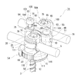
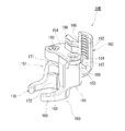
- FIG. 1 is a straightening tool according to a first embodiment of the present invention, and is a perspective view showing a state in which a screw member is clamped by the straightening tool.
- FIG. 2 is a perspective view of a screw member of a spinal deformity correction and fixation system to which the orthodontic appliance according to the first embodiment of the present invention is applied.
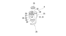
- FIG. 3 is a perspective view of a hook member of a spinal deformity correction and fixation system to which the orthodontic appliance according to the first embodiment of the present invention is applied.
- FIG. 4 is a perspective view of a clamp member used in the orthodontic appliance according to the first embodiment of the present invention.
- FIG. 5 is a clamp member used in the orthodontic appliance according to the first embodiment of the present invention, and is a perspective view from a direction different from that of FIG.
- FIG. 6 is a perspective view showing a first gear, a second gear, a rotating member, and the like used for the clamp member of the orthodontic appliance according to the first embodiment of the present invention.
- FIG. 7 is a step diagram showing a state in which the spinal deformity is corrected and fixed by the spinal deformity correction and fixing system using the orthodontic appliance according to the first embodiment of the present invention.
- FIG. 8 is a step diagram continuing from FIG. 7.
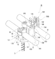
- FIG. 9 is a straightening tool according to a second embodiment of the present invention, and is a perspective view showing a state in which a screw member is clamped by the straightening tool.
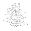
- FIG. 10 is a perspective view of a clamp member used in the orthodontic appliance according to the second embodiment of the present invention.
- FIG. 11 is a perspective view of the main body body, which is a configuration of the clamp member of the orthodontic appliance according to the second embodiment of the present invention.
- FIG. 12 is a main body body which is a configuration of a clamp member of the orthodontic appliance according to the second embodiment of the present invention, and is a perspective view from a direction different from that of FIG.
- FIG. 13 is a perspective view of a sub-body body which is a configuration of a clamp member of a straightening tool according to a second embodiment of the present invention.
- FIG. 14 is a perspective view of a wedge-shaped slide member, an operating screw member, and a regulating plate member, which are constituents of a clamp member of a straightening tool according to a second embodiment of the present invention.
- the orthodontic appliance 1A according to the first embodiment of the present invention assists the correction and fixation of the spinal deformity when the spinal deformity is corrected and fixed by the spinal deformity correction and fixation system 2 (see FIG. 8 (f)).
- the spinal deformity correction and fixation system 2 includes a plurality of screw members 3 (see FIGS. 1 and 2) screwed into the vertebral body via the vertebral arch of each vertebra of the spinal column, and the vertebral arch, vertebral arch, and lateral direction of each vertebra.
- a plurality of hook members 4 (see FIG. 3) that are hooked on protrusions and the like, and a rod member 5 that is connected to the groove 10 of each screw member 3 and the groove 24 of each hook member 4 and extends along the axial direction of the spinal column (see FIG. 1). ) And, are roughly provided.
- These screw members 3 and hook members 4 correspond to vertebral fixtures.
- the spinal deformity correction and fixing system 2 also employs other constituent members such as a connector member (not shown) so as to bridge the pair of rod members 5 and 5. Further, in the spinal deformity correction and fixing system 2 shown in FIG. 8 (f), a plurality of screw members 3 and a pair of rod members 5 and 5 are shown.
- the screw member 3, hook member 4, and rod member 5 are made of a material having excellent biocompatibility, such as titanium alloy.
- the rod member 5 is formed in a circular cross section.
- the length of the rod member 5 is appropriately set according to the degree of spinal deformation of the patient.
- the screw member 3 is screwed into the vertebral body from behind the spinal column via the pedicle of each vertebra.
- the screw member 3 is also generally referred to as a pedicle screw (vertebral arch screw).
- the screw member 3 includes a rod receiving portion 11 (head) having a groove portion 10 for receiving the rod member 5, and a screw portion 12 connected to the rod receiving portion 11 and screwed into the vertebral body via the pedicle of the vertebra. , Is equipped.
- the rod receiving portion 11 is formed in a block shape having a pair of flat portions 15 and 15 and a pair of arc portions 16 and 16 in a plan view.
- a U-shaped groove portion 10 having an open surface opposite to the screw portion 12 side is formed along the axial direction of the rod member 5.
- the groove portion 10 is formed so as to penetrate the pair of flat surface portions 15, 15.
- the rod member 5 can be received in the groove portion 10.
- female screw portions 17 and 17 are formed on the inner wall surface of the wall portion facing the groove portion 10 as a boundary, respectively.
- the set screw 20 is screwed into the female screw portions 17 and 17.
- a pair of recesses 22 and 22 are formed at positions of the flat surfaces 15 and 15 of the rod receiving portion 11 and close to the top.
- the screw portion 12 is swingably connected to the rod receiving portion 11 along the extending direction of the groove portion 10 with respect to the rod receiving portion 11.
- the swing range of the screw portion 12 with respect to the rod receiving portion 11 is a range of approximately 25 ° on one side (total swing range: approximately 50 °) from the center.
- the hook member 4 is engaged with the vertebra by hooking it on the vertebral arch root, vertebral arch, transverse process, etc. of the vertebra from the rear of the spinal column.
- the hook member 4 includes a rod receiving portion 25 (head) having a groove portion 24 for receiving the rod member 5, and a hook portion 26 integrally connected to the rod receiving portion 25.
- the rod receiving portion 25 is formed in a block shape having a pair of flat surface portions 30 and 30 and a pair of arcuate portions 31 and 31 in a plan view.
- a U-shaped groove portion 24 having an open surface opposite to the hook portion 26 side is formed along the axial direction of the rod member 5.
- the groove portion 24 is formed so as to penetrate the pair of flat surface portions 30, 30.
- the rod member 5 can be received in the U-shaped groove portion 24.
- female screw portions 32 and 32 are formed on the inner wall surface of each wall portion facing the groove portion 24 as a boundary.
- the set screw 35 is screwed into the female screw portions 32, 32.
- a pair of recesses 37, 37 are formed at positions close to the top of each of the flat surface portions 30 of the rod receiving portion 25.
- engaging groove portions 38 and 38 along the circumferential direction are formed at positions close to the top portion.
- Some hook members 4 are provided with a holding body 39 that is arranged so as to face the hook portion 26 and is movable in the axial direction. The lateral protrusions and the like can be firmly sandwiched between the sandwiching body 39 and the hook portion 26.
- the orthodontic appliance 1A according to the first embodiment of the present invention will be described in detail with reference to FIGS. 1, 4 to 6.
- the screw portion 12 side of the screw member 3 shown in FIG. 1 is the lower side
- the rod receiving portion 11 side is the upper side.
- the orthodontic appliance 1A according to the first embodiment of the present invention is positioned as a surgical instrument taken out of the body after the spinal deformity is corrected and fixed by the spinal deformity correction and fixation system 2 (see FIG. 8 (f)). As shown in FIG.
- the orthodontic appliance 1A is detachably attached to the rod receiving portion 11 (head) of the screw member 3 and is close to the rod receiving portion 11 of the screw member 3. It includes a clamp member 50A to be arranged, and an auxiliary rod member 51 that is detachably attached to the clamp member 50A and serves as a correction member for correcting spinal deformity.
- the clamp member 50A of the orthodontic appliance 1A is attached to the rod receiving portion 11 of the screw member 3, but the hook member shown in FIG. It can also be detachably attached to the rod receiving portion 25 of 4.
- the auxiliary rod member 51 is formed in a circular cross section. The outer diameter of the auxiliary rod member 51 is substantially the same as the outer diameter of the rod member 5 of the spinal deformity correction and fixing system 2.
- the clamp members 50A used in the orthodontic appliance 1A according to the first embodiment are arranged at intervals from each other so as to support the rod receiving portion 11 of the screw member 3.
- a screw support portion 54 having a pair of support pieces 111 and 111 to be formed, a rod receiving portion 55 having a U-shaped groove portion 63 having an open upper surface, and a first gear 56 arranged in the rod receiving portion 55.
- the second gear 57 which meshes with the first gear 56 and is arranged from the inside of the screw support portion 54 to the inside of the rod receiving portion 55, and the pair of support pieces 111 of the screw support portion 54, which mesh with the second gear 57.
- It is provided with a rotating member 58 that is rotatably supported so as to bridge the tip of 111.
- the pair of support pieces 111, 111 and the rotating member 58 of the screw support portion 54 correspond to the ring-shaped portion.
- the screw support portion 54 and the rod receiving portion 55 are formed of a single component. As can be seen from FIG. 5, the screw support portion 54 and the rod receiving portion 55 are integrally connected so as to partially overlap each other, and are arranged so as to be arranged in the vertical direction in a plan view. ..
- the rod receiving portion 55 has a U-shaped groove portion 63 having an open upper surface.
- the groove 63 is formed along the extending direction of the rod member 5.
- One wall portion is formed on the arc-shaped wall portion 65 whose outer peripheral surface exhibits an arc shape via the groove portion 63 of the rod receiving portion 55.
- the other wall portion is formed in the block-shaped wall portion 66 having a block shape as a whole via the groove portion 63.
- Female screw portions 67 and 67 are formed on the facing surfaces of the arc-shaped wall portion 65 and the block-shaped wall portion 66, respectively.
- the set screw 70 (see FIG. 1) is screwed into the female screw portions 67 and 67.
- the set screw 70 corresponds to a fixture.
- the bottom of the groove 63 of the rod receiving portion 55 is formed with a circular recess open to the bottom and through holes concentrically provided at the bottom of the circular recess.
- the first gear 56 (see FIG. 6) is rotatably supported in the circular recess.
- a polygonal hole portion 72 is formed through the radial center of the first gear 56.
- the first gear 56 can be rotated by fitting a dedicated surgical instrument into the polygonal hole 72 and operating the surgical instrument.
- a C ring 73 is arranged on the first gear 56. The C ring 73 slightly protrudes from the bottom surface of the groove portion 63 of the rod receiving portion 55.
- the block-shaped wall portion 66 is composed of a block main body portion 75 and a support wall portion 76 projecting upward from the block main body portion 75.
- the above-mentioned female screw portion 67 is formed in the range from the support wall portion 76 to the block main body portion 75.
- a recess 78 is formed.
- an engaging convex portion 80 that engages with an engaging groove portion 23 (see FIG. 2) provided on the outer peripheral surface of the arc portion 16 of the rod receiving portion 11 of the screw member 3 is formed.
- a pair of pillars 79, 79 are formed in the extending direction of the groove 63 with the support recess 78 as a boundary, and female screw holes (not shown) whose upper surface is opened are formed in each of the pillars 79.
- a fixing screw member 100 which will be described later, is screwed into each female screw hole.
- a support wall portion 76 having a substantially trapezoidal shape in a plan view is projected upward from the block main body portion 75 between the female screw holes of the block main body portion 75.
- a slight gap 82 (see FIG. 4) is provided between the block main body portion 75 and the support wall portion 76 on the screw support portion 54 side.
- a plate-shaped stopper member 83 is arranged in the gap 82.
- the stopper member 83 is fixed to the gap 82 by two screw members 85 and 85.
- the stopper member 83 is formed in an elongated shape along the extending direction of the groove portion 63 in a plan view.
- Concave stopper portions 84, 84 arranged so as to close a slight portion of the peripheral edge of a part of the female screw hole of the block main body portion 75 are formed at both ends of the stopper member 83 in the longitudinal direction, respectively.
- each of the pillars 79 and 79 of the block body 75 has a rectangular cross section extending upward from the outside toward the support recess 78 so as to intersect each female screw hole.
- the support space portions 88 and 88 of the above are formed so as to penetrate each other.
- the support space portion 88 is formed so as to open the screw support portion 54 side of the pillar portion 79.
- a stopper claw portion 92 is supported in each support space portion 88 so as to be reciprocating.
- the stopper claw portion 92 is formed in a plate shape and a substantially rectangular shape in a plan view.
- the stopper claw portion 92 is formed so as to penetrate an elongated hole 93 extending in the longitudinal direction.
- a fixing screw member 100 which will be described later, is inserted into the elongated hole 93.
- a claw portion 94 projecting along the longitudinal direction is formed at the end portion in the width direction.
- the stopper claw portion 92 has a claw portion 94 at the tip thereof that can appear and disappear in the support recess 78 of the block main body portion 75.
- the fixing screw member 100 is composed of a head portion 101 with a hexagonal hole and a shaft portion 102 having a male screw portion 105.
- the shaft portion 102 is composed of a small diameter shaft portion 104, a male screw portion 105, a large diameter shaft portion 106, a tapered shaft portion 107, and a minimum diameter shaft portion 108 in order from the head portion 101 side toward the tip portion. ing.
- the outer diameter of the small diameter shaft portion 104 is smaller than the outer diameter of the male screw portion 105.
- the outer diameter of the large-diameter shaft portion 106 is smaller than the outer diameter of the male screw portion 105, and is larger than the outer diameter of the small-diameter shaft portion 104.
- the tapered shaft portion 107 is formed so that its outer diameter gradually decreases from the large diameter shaft portion 106 toward the minimum diameter shaft portion 108.
- the male screw portion 105 of the fixing screw member 100 is screwed into the female screw hole of the pillar portion 79 of the block main body portion 75, and the tapered shaft portion 107 supports each pillar portion 79. It is inserted into the elongated hole 93 of the stopper claw portion 92 arranged in the space portion 88. Then, when the fixing screw member 100 is screwed in and the fixing screw member 100 is moved along the axial direction, the tapered shaft portion 107 of the fixing screw member 100 comes into contact with the inner wall surface of the elongated hole 93 of the stopper claw portion 92. In order to move while moving, the stopper claw portion 92 can move back and forth with respect to the inside of the support recess 78 of the block main body portion 75.
- the screw support portion 54 extends so as to be integrally separated from the gear accommodating portion 110 connected to the rod receiving portion 55 so as to overlap with each other in the vertical direction.
- a pair of support pieces 111 and 111 extending integrally from the lower ends of the pillars 79 and 79 in the block main body 75 of the rod receiving portion 55 are provided.
- the lower part of the gear accommodating portion 110 is open, and the second gear 57 (see FIG. 6) is accommodated in the gear accommodating portion 110.
- the pair of support pieces 111 and 111 are also formed with accommodating recesses (not shown) that are open downward.
- the rotating member 58 is arranged in the accommodating recesses of the pair of support pieces 111 and 111 so as to cross the gear accommodating portion 110.
- a substantially C-shaped cover member 115 is arranged on the screw support portion 54 so as to cover the second gear 57 in the gear accommodating portion 110 and the rotating member 58 in the pair of support pieces 111 and 111 from below. There is.
- the cover member 115 is formed with a protruding portion 116 protruding radially outward on the side opposite to the open portion in the radial direction.
- the second gear 57 is rotatably supported by a support pin 117 erected from the protrusion 116.
- the second gear 57 is arranged from the gear accommodating portion 110 of the screw support portion 54 to a portion close to the first gear 56 in the bottom portion of the rod receiving portion 55 and meshes with the first gear 56.
- the second gear 57 also meshes with the gear portion 118 of the rotating member 58.
- the distance between the pair of support pieces 111 and 111 is such that the pair of flat surface portions 15 and 15 provided on the rod receiving portion 11 of the screw member 3 can abut and fit between the pair of support pieces 111 and 111. It is set.
- the rotating member 58 is formed in a C shape.
- the rotating member 58 extends to a housing recess in the pair of support pieces 111, 111 so as to cross the gear housing portion 110, and is rotatably supported so as to bridge the tips of the pair of support pieces 111, 111. ..
- a gear portion 118 is formed on the outer peripheral surface of the rotating member 58.
- the gear portion 118 meshes with the second gear 57.
- the inner diameter of the rotating member 58 substantially coincides with the outer diameter of the pair of arc portions 16 and 16 (see FIG. 2) of the rod receiving portion 11 of the screw member 3. Then, by rotating the first gear 56 with a dedicated surgical instrument, the second gear 57 and the rotating member 58 can be rotated. As a result, the rotation of the rotating member 58 makes it possible to open and close between the pair of support pieces 111 and 111 of the screw support portion 54.
- a special surgical instrument (not shown) is fitted into the polygonal hole 72 of the first gear 56 arranged in the bottom of the groove 63 of the rod receiving portion 55, and the rod receiving portion 55 is rotated in the other direction.
- the first gear 56, the second gear 57, and the rotating member 58 are rotated so that the rotating member 58 closes between the pair of support pieces 111 and 111 of the screw support portion 54.
- the inner peripheral surface of the rotating member 58 is brought into contact with the outer peripheral surface of the other arc portion 16 of the rod receiving portion 11 of the screw member 3, and the rotating member 58 causes the rod receiving portion 11 of the screw member 3 to abut.
- the groove portion 10 of the screw member 3 (rod receiving portion 11) is exposed to the outside while restraining the rod member 3.
- each fixing screw member 100 is advanced along the axial direction.
- the tapered shaft portion 107 of each fixing screw member 100 advances while contacting the inner wall surface of the elongated hole 93 of each stopper claw portion 92, so that each stopper claw portion 92 advances while contacting the inner wall surface of the elongated hole 93 of each stopper claw portion 92.
- each stopper claw portion 92 presses the recess 22 provided in each flat surface portion 15 of the rod receiving portion 11 of the screw member 3, and the pair of stopper claw portions 92, 92 causes the screw member.
- the rod receiving portion 11 of 3 is firmly sandwiched and fixed from the pair of flat surface portions 15 and 15 sides.
- each fixing screw member 100 is retracted along the axial direction. Then, since the tapered shaft portion 107 of each fixing screw member 100 retracts, each stopper claw portion 92 slides in the support space portion 88 under its own weight. As a result, the claw portion 94 of each stopper claw portion 92 is separated from the recess 22 provided in each flat surface portion 15 of the rod receiving portion 11 of the screw member 3, and the rod receiving portion 11 of the screw member 3 by each stopper claw portion 92. The pinching action is released.
- a special surgical instrument (not shown) is fitted into the polygonal hole 72 of the first gear 56 arranged in the bottom of the groove 63 of the rod receiving portion 55, and the rod receiving portion 55 is rotated in one direction to obtain the first gear.
- the clamp member 50A is pulled from the rod receiving portion 11 of the screw member 3 in a state where the gear 56, the second gear 57, and the rotating member 58 are rotated to open the space between the pair of support pieces 111 and 111 of the screw support portion 54. Can be removed.
- FIGS. 7 and 8 As the spinal deformity correction and fixing system 2, the spinal deformity is straightened and fixed only by a plurality of screw members 3 and a pair of rod members 5, but this relates to the first embodiment.
- a hook member 4 and a connector member (not shown) are used as necessary.
- a rod member may be additionally used.
- a screw member 3 is attached to each vertebra in the corrective fixation range of the spinal column (for example, 10 vertebrae in the figure). It is screwed into the vertebral body from the posterior via its pedicle. Subsequently, for example, in the case of a single curve as shown in FIG. 7, a clamp member is clamped to a rod receiving portion 11 of each screw member 3 screwed into, for example, five vertebrae in the range from the top of the curve to the vicinity of the top. Install each 50A.
- the clamp member 50A is attached so that the rod receiving portion 55 is arranged outside the rod receiving portion 11 of the screw member 3 in the left-right direction of the patient. Since the method of attaching the clamp member 50A to the rod receiving portion 11 of the screw member 3 is described above, the description thereof is omitted here.
- one auxiliary rod member 51 is prepared, and the auxiliary rod member 51 is curved using a dedicated surgical instrument (not shown) so as to follow the scoliosis curve of the spinal column. Subsequently, as shown in FIG. 7B, the auxiliary rod member 51 is engaged with the groove portion 63 of the rod receiving portion 55 of each clamp member 50A. Subsequently, using a dedicated surgical instrument (not shown), the set screw 70 is screwed into the female screw portions 67, 67 of the rod receiving portion 55 of each clamp member 50A, and the auxiliary rod members 51 are temporarily fixed.
- the auxiliary rod member 51 is gripped and rotated by using a dedicated surgical instrument (not shown), or each clamp member 50A is moved in the approaching direction or far away. Perform a directional movement to correct spinal deformities, including twisting.
- the set screw 70 of the orthodontic appliance 1A according to the first embodiment is finally tightened, and the auxiliary rod member 51 is placed in the groove portion 62 of the rod receiving portion 55 of each clamp member 50A. Securely fix.
- the spinal column deformation can be corrected by the orthodontic appliance 1A according to the first embodiment and the state can be maintained.
- FIG. 7C the set screw 70 of the orthodontic appliance 1A according to the first embodiment
- the rod member 5 is engaged with the groove portion 10 of the rod receiving portion 11 of all the screw members 3 (10 pieces) on the left side to which the clamp member 50A is not attached.
- the set screw 20 is screwed into the female screw portions 17 and 17 (see FIG. 2) of the rod receiving portion 11 of each screw member 3 and finally tightened, and the rod member 5 is screwed into each screw member. It is firmly fixed to the groove portion 10 of the rod receiving portion 11 of 3.
- the rod member 5 is slightly curved along the (physiological) normal lordosis and kyphosis of the patient, and in that state, all the screw members 3 (10 pieces) It can also engage with the groove 10 of the rod receiving portion 11.
- the rod member 5 is engaged with the groove portion 10 of the rod receiving portion 11 of all the screw members 3 (10 pieces) on the right side to which the clamp member 50A is attached.
- the set screw 20 is screwed into the female screw portions 17 and 17 (see FIG. 2) of the rod receiving portion 11 of each screw member 3 and fully tightened to firmly tighten the rod member 5 into the groove portion 10 of the rod receiving portion 11 of each screw member 3. Fix it.
- the set screw 70 is removed from the rod receiving portion 55 of each clamp member 50A, and the auxiliary rod member 51 is removed from each clamp member 50A.
- each clamp member 50A is removed from the rod receiving portion 11 of each screw member 3, and the correction and fixation of the spinal column deformation by the spinal column deformation correction and fixing system 2 (a plurality of screw members 3 and a pair of rod members 5) is completed. .. Since the method of removing the clamp member 50A from the rod receiving portion 11 of the screw member 3 is described above, the description thereof is omitted here.
- the clamp member 50A is attached so that the rod receiving portion 55 thereof is arranged outside the rod receiving portion 11 of the screw member 3 in the left-right direction of the patient.
- the clamp member 50A may be attached to the rod receiving portion 11 of the screw member 3 so that the rod receiving portion 55 is arranged inside the rod receiving portion 11 of the screw member 3 in the left-right direction of the patient.
- the clamp member 50A is attached to the rod receiving portion 11 of each screw member 3 on the right side in the left-right direction of the patient, but the rod receiving portion of each screw member 3 on the left side in the left-right direction is attached.
- the clamp member 50A may be attached to 11, or the clamp member 50A may be attached to the rod receiving portions 11 of the screw members 3 on both sides in the left-right direction.
- the clamp members 50A are attached to the rod receiving portions 11 of the selected screw member 3 according to the intention of the operator, and the clamp members 50A and the respective clamp members 50A and The correction operation may be performed by the auxiliary rod member 51 to assist the correction and fixation of the spinal column deformation by the spinal column deformation correction and fixation system 2.
- the method is not limited to the method shown in FIGS. 7 and 8, but a method other than the method shown in FIGS. 7 and 8 is used according to the intention of the operator. It is possible to adopt.
- the orthodontic appliance 1A is detachably attached to, for example, the rod receiving portion 11 of the spinal column deformation correction and fixing system 2, and the rod of the screw member 3. It includes a clamp member 50A arranged close to the receiving portion 11, and an auxiliary rod member 51 that is detachably attached to the rod receiving portion 55 of the clamp member 50A to correct spinal deformity.
- the clamp member 50A is attached to each of the plurality of screw members 3, and the auxiliary rod member 51 is further attached to the groove 63 of the rod receiving portion 55 of each clamp member 50A.
- the spinal column deformation can be appropriately corrected via each clamp member 50A and each screw member 3, and the corrected state can be maintained.
- the rod member 5 is connected to the groove 10 of the rod receiving portion 11 of each screw member 3 to fix the spinal column in a corrected state.
- the auxiliary rod member 51 and each clamp member 50A are removed from each screw member 3 and taken out of the body.
- the rod member 5 of the spinal deformity correction and fixation system 2 is fixed to each of the scoliotic vertebrae including the twist as in the conventional case. It is not necessary to engage with the screw member 3 or the hook member 4, and the rod member 5 of the spinal deformity correction and fixation system 2 is curved so as to follow the scoliosis deformation, and is strengthened by using a special surgical instrument such as a plier. There is no need for operations such as pinching and rotating. As a result, damage to the rod member 5 which is a material buried in the body can be suppressed.
- the rod member 5 of the spinal deformity correction and fixing system 2 can be replaced with the groove portion 10 (25) of the rod receiving portion 11 (25) of each screw member 3 (hook member 4). 24) can be easily engaged (connected), and as a result, the spinal deformity correction and fixation system 2 makes it possible to easily correct the spinal deformity, and the operation itself becomes easy, so that the operation time can be increased. It can also contribute to shortening.
- the clamp member 50A adopted in the straightening tool 1A according to the first embodiment of the present invention is a pair of screw support portions 54 as ring-shaped portions that support the screw member 3 so as to surround the outer circumference of the rod receiving portion 11. Support pieces 111 and 111, and a rotating member 58 that is rotatably supported so as to open and close between the tips of the pair of support pieces 111 and 111.
- the groove portion 10 for engaging the rod member 5 provided in the rod receiving portion 11 of the screw member 3 can be exposed to the outside.
- the clamp member 50A and the auxiliary rod member 51 can easily engage the rod member 5 with the groove 10 of each screw member 3 in a state where the spinal column deformation is corrected and the state is maintained.
- the clamp member 50A adopted in the straightening tool 1A according to the first embodiment of the present invention includes a set screw 70 for fixing the auxiliary rod member 51 to the groove portion 63 of the rod receiving portion 55 of the clamp member 50A.
- a set screw 70 for fixing the auxiliary rod member 51 to the groove portion 63 of the rod receiving portion 55 of the clamp member 50A.
- the clamp member 50A adopted in the straightening tool 1A according to the first embodiment of the present invention opens and closes between the tips of the pair of support pieces 111 and 111 and the pair of support pieces 111 and 111 of the screw support portion 54.
- a pair of stopper claws 92 and 92 that sandwich the rod receiving portion 11 of the screw member 3 are provided.
- the pair of stopper claws 92, 92 can further firmly fix the clamp member 50A to the screw member 3.
- the corrective force from the clamp member 50A can be appropriately transmitted to the vertebrae via the screw member 3, and the spinal column deformation can be appropriately corrected.
- a recess 22 for supporting the tip of the claw portion 94 of the stopper claw portion 92 is formed on the flat surface portion 15 of the screw member 3, and the clamp member 50A is screwed.
- the stopper claw portion 92 of the clamp member 50A engages with the recess 22 of the screw member 3, so that the clamp member 50A is attached to the screw member 3 when the clamp member 50A is attached to the screw member 3. You can eliminate backlash as much as possible.
- the auxiliary rod member 51 engaged with the groove 63 of the rod receiving portion 55 of the clamp member 50A is adopted as the straightening member, but the clamp is used as the straightening member.
- a shaft member or the like that is detachably attached to the member 50A and extends outward from the clamp member 50A may be adopted.
- the operator can appropriately correct the spinal deformity by grasping and operating each shaft member protruding outside the body or by operating with a surgical instrument. It is also possible to attach a straightening maintenance member or the like for maintaining the straightening state to the tip of each shaft member.
- the orthodontic appliance 1A according to the first embodiment is positioned as a surgical instrument that is taken out of the body after the spinal deformity is corrected and fixed by the spinal deformity correction and fixation system 2, but it can be left as it is in the body.
- the orthodontic tool 1A according to the first embodiment has excellent biocompatibility with titanium alloy or the like, like the screw member 3, hook member 4, rod member 5, etc. of the spinal deformity correction and fixing system 2. It is necessary to form it with a new material. As a result, the rigidity of the spinal column deformation correction and fixing system 2 as a whole can be improved, and breakage of the rod member 5 and the like can be suppressed.
- the orthodontic appliance 1B according to the second embodiment of the present invention will be described in detail with reference to FIGS. 9 to 14.
- the structure of the clamp member 50B adopted in the orthodontic appliance 1B according to the second embodiment is different from the structure of the clamp member 50A adopted in the orthodontic appliance 1A according to the first embodiment, the structure of the clamp member 50B is described in detail. This will be described below.
- the clamp member 50B includes a pair of support pieces 160 and 170 that are provided so as to support the rod receiving portion 11 of the screw member 3 so as to be able to move close to each other and move away from each other.
- a rod receiving portion 162 having a U-shaped groove portion 167 that is integrally connected to one of the support pieces 160 and has an open upper surface, and a pair of supports by moving in the vertical direction.
- a wedge-shaped slide member 152 for moving the other support piece 170 with respect to the one support piece 160 so as to be able to move close to and away from the support piece 160 is provided.
- the clamp member 50B includes a main body main body 150 shown in FIGS. 11 and 12, a sub body main body 151 shown in FIG. 13, and a wedge-shaped slide member 152 shown in FIG.
- the operating screw member 153 shown in FIG. 14 and the regulating plate member 154 shown in FIG. 14 are connected and integrated.
- the main body main body 150 is configured by integrally connecting one support piece 160, the main body main body portion 161 and the rod receiving portion 162.
- One support piece 160 extends from the lower end of the main body main body portion 161 in a direction substantially orthogonal to the extending direction of the groove portion 167 of the rod receiving portion 162. Further, one support piece 160 is the lower end of the main body main body portion 161 and extends from one end side along the extending direction of the groove portion 167 of the rod receiving portion 162.
- An arcuate screw contact surface 163 is provided on the front surface of the main body main body 161 (the surface on the side of one support piece 160) so as to be continuous with the one support piece 170.
- One arc portion 16 provided on the rod receiving portion 11 of the screw member 3 shown in FIG. 9 is brought into contact with the screw contact surface 163.
- the rod receiving portion 162 is integrally connected to the back surface side of the main body main body portion 161 (the surface opposite to one of the support pieces 160).
- the upper surface is opened in an arbitrary shape, the other end side in the extending direction of the groove portion 167 of the rod receiving portion 162 is opened, and the rod is opened in the front surface (the surface on one support piece 160 side).
- a housing hollow portion 165 that opens in a substantially rectangular shape along the extending direction of the groove portion 167 of the receiving portion 162 is formed.
- the sub-body main body portion 171 and the wedge-shaped slide member 152 of the sub-body main body 151 which will be described in detail later, are formed in the inclined space portion 178 provided in the sub-body main body portion 171 and the wedge-shaped slide member 152.
- the wedge-shaped protrusion 182 provided is accommodated in an engaged state.
- a housing recess 164 is formed on the upper surface of the main body main body 161 at one end on the support piece 160 side.
- the rod receiving portion 162 has a U-shaped groove portion 167 with an open upper surface.
- the groove portion 167 is formed along the extending direction of the rod member 5 (see FIG. 9).
- Female thread portions 168 and 168 are formed on the inner wall surfaces of the wall portions 166 and 166 facing each other via the groove portion 167 of the rod receiving portion 162, respectively.
- the set screw 169 shown in FIG. 9 is screwed into these female screw portions 168 and 168. This set screw 169 corresponds to a fixture that fixes the auxiliary rod member 51 to the groove portion 167 of the clamp member 50B.
- the rod receiving portion 162 that is, the wall portion 166, 166 thereof is fixed so as to cover the upper surface of the main body main body portion 161 as shown in FIG. 11 and the upper surface of the main body main body portion 161 as shown in FIG. It protrudes above the regulatory plate member 154.
- a rod-shaped surgical instrument (not shown) for assisting the operation of inserting the auxiliary rod member 51 (see FIG. 9) into the groove portion 167 of the rod receiving portion 162 into the protruding portion of the wall portions 166 and 166 (not shown). It becomes possible to attach the tip of.
- the bottom surface of the groove portion 167 of the rod receiving portion 162 is located above one of the support pieces 160. Further, as shown in FIG.
- the sub-body main body 151 is configured by integrally connecting the other support piece 170 and the sub-body main body 171.
- the other support piece 170 extends from the lower end of the sub-body main body 171 in a direction substantially orthogonal to the extending direction of the groove 167 of the rod receiving portion 162.
- the other support piece 170 is the lower end of the sub-body main body 171 and extends from the other end along the extending direction of the groove 167 of the rod receiving portion 162.
- the sub-body main body 171 is provided with a plate-shaped main body 174 having a predetermined width and standing along a direction extending to a groove 167 of the rod receiving portion 162, and a back surface (the other) of the plate-shaped main body 174. It includes a pair of inclined large tops 175A and inclined small tops 175B that are integrally connected to the surface on the side opposite to the support piece 170).
- An arc-shaped screw contact surface 172 is provided below the plate-shaped main body portion 174 of the sub-body main body portion 171 so as to be continuous with the other support piece 170 at intervals.
- One arc portion 16 provided on the rod receiving portion 11 of the screw member 3 shown in FIG. 9 is brought into contact with the screw contact surface 172.
- an inclined space portion 178 that inclines downward to the other support piece 170 side (the other end side) with a predetermined width is formed.
- the thickness of the inclined small top portion 175B on one end side is formed to be thinner than the thickness of the inclined large top portion 175A on the other end side.
- a wedge-shaped protrusion 182 (see FIG. 14) provided on the wedge-shaped slide member 152 is engaged with the inclined space portion 178.
- the wedge-shaped slide member 152 includes a plate-shaped portion 180 and a cylindrical portion 181 integrally connected to one end of the plate-shaped portion 180.
- the entire wedge-shaped slide member 152 is housed in a housing hollow portion 165 provided in the main body body 161 of the main body body 150.
- the plate-shaped portion 180 is provided in a standing state, and a wedge-shaped protruding portion 182 is projected from the front surface of the plate-shaped portion 180 at the other end opposite to the cylindrical portion 181 side.
- the wedge-shaped protrusion 182 is formed in a substantially parallel four-sided shape in front view, which is inclined downward toward the mounting bolt 193 side (the other end side) with a predetermined width.
- the wedge-shaped protrusion 182 is engaged with the inclined space portion 178 provided in the sub-body main body 151, and the widths and lengths of the wedge-shaped protrusions 182 are substantially the same.
- a female screw portion (not shown) is formed on the inner peripheral surface of the cylindrical portion 181. The male threaded portion 190 of the operating threaded member 153 is screwed into the female threaded portion.
- the operating screw member 153 is composed of a head 189 having a hexagonal hole 188 on the upper surface, and a male screw portion 190 continuously provided along the axial direction from the head 189.
- the male threaded portion 190 is screwed into the female threaded portion provided on the inner peripheral surface of the cylindrical portion 181 of the wedge-shaped slide member 152.
- the head 189 of the operation screw member 153 is housed in a storage recess 164 provided on the upper surface of the main body body 161 of the main body body 150.
- a regulation plate member 154 that regulates the vertical movement of the operation screw member 153 is arranged on the head 189 of the operation screw member 153. That is, as shown in FIG.
- the head portion 189 of the operation screw member 153 is sandwiched between the accommodating recess 164 of the main body main body 150 (main body main body portion 161) and the regulation plate member 154. It is supported so that it can rotate freely and cannot move along the vertical direction.
- An opening 192 is formed in the regulating plate member 154 at a position corresponding to the head 189 of the operating screw member 153 so that the hexagonal hole 188 provided in the head 189 of the operating screw member 153 is exposed to the outside. Will be done.
- the regulation plate member 154 covers the upper surface of the main body main body 161 of the main body main body 150 and the head 189 of the operation screw member 153 by the mounting bolt 193. It is fixed to the main body body 150.
- the regulation plate member 154 is formed with the opening 192, the hexagonal hole 188 provided in the head 189 of the operation screw member 153 is exposed to the outside.
- the sub-body main body portion 171 of the sub-body main body 151 and the wedge-shaped slide member 152 are engaged with the wedge-shaped protrusion 182 provided on the wedge-shaped slide member 152 on the inclined space portion 178 provided on the sub-body main body 151.
- the wedge-shaped slide member 152 is movably accommodated along the vertical direction
- the sub-body body 151 is movably accommodated along the extending direction of the groove portion 167 of the rod receiving portion 162.
- one support piece 160 of the main body body 150 and the other support piece 170 of the sub body body 151 are arranged so as to face each other.
- the male screw portion 190 of the operation screw member 153 is arranged in a state of being screwed into the female screw portion of the cylindrical portion 181 of the wedge-shaped slide member 152.
- the head 189 of the operation screw member 153 is housed in the storage recess 164 of the main body body 150 (main body body 161), and the upper surface of the head 189 and the main body body 150 (main body body 161) are housed.
- the upper surface excluding the recess 164 is arranged on substantially the same plane.
- the regulation plate member 154 is arranged so as to cover the upper surface of the main body main body 161 of the main body main body 150 and the head 189 of the operation screw member 153, and is fixed to the main body main body 150 by the mounting bolts 193. Will be done. In this way, the clamp member 50B used for the orthodontic appliance 1B according to the second embodiment is completed.
- the clamp member 50A is arranged so that the pair of support pieces 160 and 170 are a pair of flat surface portions 15 and 15 in the rod receiving portion 11 of the screw member 3 and face the portions below the groove portion 10, respectively. Place in. At this time, one arc portion 16 of the rod receiving portion 11 of the screw member 3 hits the screw contact surface 163 on the main body body 150 side and the screw contact surface 172 on the sub body body 151 side of the clamp member 50A, respectively. Be touched.
- a special surgical instrument (not shown) is attached to the hexagonal hole 188 of the head 189 of the operation screw member 153, and the special surgical instrument is rotated in the other direction to make the operation screw member 153 another. Rotate in the direction.
- the wedge-shaped slide member 152 moves downward, the wedge-shaped protrusion 182 provided on the wedge-shaped slide member 152 and the pair of inclined large top portions 175A and the inclined portion 175A provided on the sub-body main body portion 171 of the sub-body main body 151 are inclined. Due to the wedge effect with the small top portion 175B, the other support piece 170 provided in the sub-body main body 151 moves in a direction close to the one support piece 160 provided in the main body main body 150.
- the pair of support pieces 160 and 170 of the clamp member 50B sandwich the pair of flat surfaces 15 and 15 in the rod receiving portion 11 of the screw member 3 below the groove 10 from both sides. Can be clamped firmly. At this time, the pair of support pieces 160 and 170 of the clamp member 50B sandwich the pair of flat surfaces 15 and 15 in the rod receiving portion 11 of the screw member 3 below the groove portion 10, so that the screw member 3 The groove portion 10 of the (rod receiving portion 11) can be exposed to the outside.
- the clamp member 50B used in the orthodontic appliance 1B according to the second embodiment of the present invention includes a pair of support pieces 160 and 170 that are provided so as to be able to move close to each other and move away from each other.
- the 160 and 170 allow the pair of flat surfaces 15 and 15 of the rod receiving portion 11 of the screw member 3 to be firmly clamped so as to sandwich the portion below the groove 10 from both sides.
- the groove portion 10 provided in the rod receiving portion 11 of the screw member 3 can be exposed to the outside.
- the rod member 5 can be easily engaged with the groove portion 10 of each screw member 3 in a state where the spinal column deformation is corrected and the state is maintained by the clamp member 50B and the auxiliary rod member 51.
Landscapes
- Health & Medical Sciences (AREA)
- Orthopedic Medicine & Surgery (AREA)
- Life Sciences & Earth Sciences (AREA)
- Neurology (AREA)
- Surgery (AREA)
- Heart & Thoracic Surgery (AREA)
- Engineering & Computer Science (AREA)
- Biomedical Technology (AREA)
- Nuclear Medicine, Radiotherapy & Molecular Imaging (AREA)
- Medical Informatics (AREA)
- Molecular Biology (AREA)
- Animal Behavior & Ethology (AREA)
- General Health & Medical Sciences (AREA)
- Public Health (AREA)
- Veterinary Medicine (AREA)
- Surgical Instruments (AREA)
Abstract
Description
以下に示す発明の態様は、本発明の構成を例示するものであり、本発明の多様な構成の理解を容易にするために、項分けして説明するものである。各項は、本発明の技術的範囲を限定するものではなく、発明を実施するための最良の形態を参酌しつつ、各項の構成要素の一部を置換し、削除し、又は、更に他の構成要素を付加したものについても、本願発明の技術的範囲に含まれるものである。
(8)項に記載の矯正具では、その全体をコンパクトに構成することができる。
(9)項に記載の矯正具では、クランプ部材のストッパ爪部が、椎骨固定具の凹部に係合することで、クランプ部材を椎骨固定具に取り付けた際の、クランプ部材の椎骨固定具に対するガタを極力無くすことができる。
まず、本発明の第1実施形態に係る矯正具1Aを図1~図8に基づいて詳しく説明する。
本発明の第1実施形態に係る矯正具1Aは、脊柱変形矯正固定システム2(図8(f)参照)にて脊柱変形を矯正固定する際に、その矯正固定を補助するものである。脊柱変形矯正固定システム2は、脊柱の各椎骨の椎弓根を介して椎体にねじ込まれる複数のスクリュー部材3(図1及び図2参照)と、各椎骨の椎弓根や椎弓、横突起等に引っ掛ける複数のフック部材4(図3参照)と、各スクリュー部材3の溝部10及び各フック部材4の溝部24に連結され、脊柱の軸方向に沿って延びるロッド部材5(図1参照)と、を概略備えている。これらスクリュー部材3及びフック部材4が、椎骨固定具に相当する。なお、脊柱変形矯正固定システム2には、一対のロッド部材5、5を架け渡すようにコネクタ部材(図示略)等、他の構成部材も採用される。また、図8(f)に示す、脊柱変形矯正固定システム2では、複数のスクリュー部材3と、一対のロッド部材5、5とが示されている。
次に、図8(f)に示すように、各クランプ部材50Aのロッド受入部55からセットスクリュー70を取り外して、補助ロッド部材51を各クランプ部材50Aから取り外す。続いて、各クランプ部材50Aを各スクリュー部材3のロッド受入部11から取り外して、脊柱変形矯正固定システム2(複数のスクリュー部材3及び一対のロッド部材5)による脊柱変形の矯正固定が完了される。なお、クランプ部材50Aをスクリュー部材3のロッド受入部11から取り外す方法は、上述しているためにここでの説明は省略する。
Claims (7)
- 脊柱の各椎骨にそれぞれ固定される椎骨固定具と、該椎骨固定具に連結されるロッド部材と、を備えた脊柱変形矯正固定システムにて脊柱変形を矯正固定する際に、その矯正固定を補助する矯正具であって、
前記椎骨固定具に着脱自在に取り付けられ、該椎骨固定具に近接して配置されるクランプ部材と、
該クランプ部材に着脱自在に取り付けられ、脊柱変形を矯正するための矯正部材と、
を備えることを特徴とする矯正具。 - 前記クランプ部材は、溝部を有し、
前記矯正部材は、前記クランプ部材の溝部に係合可能な補助ロッド部材であることを特徴とする請求項1に記載の矯正具。 - 前記クランプ部材は、前記椎骨固定具の頭部を挟み込むように支持する、互いに近接・遠退自在に設けられる一対の支持片を有することを特徴とする請求項1または2に記載の矯正具。
- 前記クランプ部材は、前記椎骨固定具の頭部の外周を取り巻くように支持するリング状部を備えていることを特徴とする請求項1または2に記載の矯正具。
- 前記クランプ部材は、前記補助ロッド部材を前記クランプ部材の溝部に固定するための固定具を備えていることを特徴とする請求項2~4いずれかに記載の矯正具。
- 前記クランプ部材は、前記椎骨固定具の頭部を挟持する一対のストッパ爪部を備えていることを特徴とする請求項4または5に記載の矯正具。
- 前記矯正具は、前記脊柱変形矯正固定システムにより脊柱変形が矯正固定された状態で、体外に取り出される手術器具として前記椎骨固定具から取り外し可能に構成されることを特徴とする請求項1~6いずれかに記載の矯正具。
Priority Applications (3)
| Application Number | Priority Date | Filing Date | Title |
|---|---|---|---|
| JP2021530014A JP7584049B2 (ja) | 2019-07-01 | 2020-06-29 | 矯正具 |
| EP20834386.3A EP3995093B1 (en) | 2019-07-01 | 2020-06-29 | Correction device |
| US17/624,078 US20220354542A1 (en) | 2019-07-01 | 2020-06-29 | Corrective appliance |
Applications Claiming Priority (2)
| Application Number | Priority Date | Filing Date | Title |
|---|---|---|---|
| JP2019122920 | 2019-07-01 | ||
| JP2019-122920 | 2019-07-01 |
Publications (1)
| Publication Number | Publication Date |
|---|---|
| WO2021002323A1 true WO2021002323A1 (ja) | 2021-01-07 |
Family
ID=74100513
Family Applications (1)
| Application Number | Title | Priority Date | Filing Date |
|---|---|---|---|
| PCT/JP2020/025521 Ceased WO2021002323A1 (ja) | 2019-07-01 | 2020-06-29 | 矯正具 |
Country Status (4)
| Country | Link |
|---|---|
| US (1) | US20220354542A1 (ja) |
| EP (1) | EP3995093B1 (ja) |
| JP (1) | JP7584049B2 (ja) |
| WO (1) | WO2021002323A1 (ja) |
Families Citing this family (2)
| Publication number | Priority date | Publication date | Assignee | Title |
|---|---|---|---|---|
| WO2023023340A2 (en) * | 2021-08-20 | 2023-02-23 | Snj Patents, Llc | Minimally invasive surgery add on screw system |
| US12268421B2 (en) * | 2022-12-28 | 2025-04-08 | Warsaw Orthopedic, Inc. | Surgical system and methods of use |
Citations (5)
| Publication number | Priority date | Publication date | Assignee | Title |
|---|---|---|---|---|
| US20120203279A1 (en) * | 2011-02-08 | 2012-08-09 | Alphatec Spine, Inc. | Systems and methods for correcting spinal deformities |
| JP2012213625A (ja) | 2011-03-31 | 2012-11-08 | Spinelab Ag | 脊柱インプラント |
| US20140316475A1 (en) * | 2013-02-28 | 2014-10-23 | Alphatec Spine, Inc. | Spinal deformity correction instruments and methods |
| US20140350612A1 (en) * | 2011-06-23 | 2014-11-27 | Stéphane Leroux | Surgical device for correcting deformations in the spinal column |
| US20140364912A1 (en) * | 2013-06-11 | 2014-12-11 | Warsaw Orthopedic, Inc. | Spinal correction system |
Family Cites Families (8)
| Publication number | Priority date | Publication date | Assignee | Title |
|---|---|---|---|---|
| WO2015023420A2 (en) * | 2013-07-25 | 2015-02-19 | Latitude Holdings, Llc | Percutaneous pedicle screw revision system |
| US10709480B2 (en) * | 2014-04-16 | 2020-07-14 | Dynamic Spine, Llc | Adjustable screw-clamp orthopedic apparatus |
| US9724131B2 (en) * | 2014-09-25 | 2017-08-08 | DePuy Synthes Products, Inc. | Spinal connectors and related methods |
| US10321939B2 (en) * | 2016-05-18 | 2019-06-18 | Medos International Sarl | Implant connectors and related methods |
| US10786285B2 (en) * | 2016-06-06 | 2020-09-29 | Stryker European Holdings I, Llc | Paraxial revision rod-to-rod connector |
| US10136928B2 (en) * | 2016-09-14 | 2018-11-27 | Globus Medical, Inc. | Rod link reducer |
| US10238432B2 (en) * | 2017-02-10 | 2019-03-26 | Medos International Sàrl | Tandem rod connectors and related methods |
| US20180228516A1 (en) * | 2017-02-14 | 2018-08-16 | Warsaw Orthopedic, Inc. | Spinal implant system and method |
-
2020
- 2020-06-29 WO PCT/JP2020/025521 patent/WO2021002323A1/ja not_active Ceased
- 2020-06-29 EP EP20834386.3A patent/EP3995093B1/en active Active
- 2020-06-29 JP JP2021530014A patent/JP7584049B2/ja active Active
- 2020-06-29 US US17/624,078 patent/US20220354542A1/en not_active Abandoned
Patent Citations (5)
| Publication number | Priority date | Publication date | Assignee | Title |
|---|---|---|---|---|
| US20120203279A1 (en) * | 2011-02-08 | 2012-08-09 | Alphatec Spine, Inc. | Systems and methods for correcting spinal deformities |
| JP2012213625A (ja) | 2011-03-31 | 2012-11-08 | Spinelab Ag | 脊柱インプラント |
| US20140350612A1 (en) * | 2011-06-23 | 2014-11-27 | Stéphane Leroux | Surgical device for correcting deformations in the spinal column |
| US20140316475A1 (en) * | 2013-02-28 | 2014-10-23 | Alphatec Spine, Inc. | Spinal deformity correction instruments and methods |
| US20140364912A1 (en) * | 2013-06-11 | 2014-12-11 | Warsaw Orthopedic, Inc. | Spinal correction system |
Non-Patent Citations (1)
| Title |
|---|
| See also references of EP3995093A4 |
Also Published As
| Publication number | Publication date |
|---|---|
| EP3995093A1 (en) | 2022-05-11 |
| EP3995093A4 (en) | 2023-07-26 |
| JP7584049B2 (ja) | 2024-11-15 |
| EP3995093B1 (en) | 2025-08-06 |
| US20220354542A1 (en) | 2022-11-10 |
| JPWO2021002323A1 (ja) | 2021-01-07 |
Similar Documents
| Publication | Publication Date | Title |
|---|---|---|
| JP5864663B2 (ja) | 脊椎手術を行うシステムおよび方法 | |
| US11690654B2 (en) | Adjustable fixation device | |
| US9572601B2 (en) | Spinal correction adjustment systems and methods | |
| JPH05505749A (ja) | 脊柱変形処理装置 | |
| JPH09510628A (ja) | 側湾脊柱の減捻を達成させる工具及び方法 | |
| JP2007307394A (ja) | 脊椎を固定するための装置 | |
| CN103717159A (zh) | 包括椎骨对齐特征的微创脊柱固定系统 | |
| EP2637583A1 (en) | Bone anchor | |
| JP2001252283A (ja) | ロッド固定装置 | |
| JP2008515488A (ja) | 広範な多軸留め具組立体を備えた脊椎インプラント | |
| CN102006830A (zh) | 具有减小凸片的骨固定元件 | |
| JP7584049B2 (ja) | 矯正具 | |
| EP1919381B1 (en) | Apparatus for external fixation of the pelvic ring | |
| JP2007508118A (ja) | 脊椎固定フックおよび脊椎固定方法 | |
| RU170604U1 (ru) | Медицинский инструмент для временной стабилизации позвоночного столба при исправлении его деформации | |
| JPH10248855A (ja) | 椎体固定具を体外で脊椎に固定する椎体固定具取付け装置およびこの椎体固定具取付け装置を用いた脊椎矯正装置 | |
| EP3733100A1 (en) | Spinal fixation system | |
| JP7702699B2 (ja) | 体外矯正具 | |
| JPWO2019117251A1 (ja) | 脊椎固定システム | |
| KR100507615B1 (ko) | 척추경 나사못 및 이를 갖는 척추경 나사못 조립체 | |
| WO2026088682A1 (ja) | 体外矯正具 | |
| JP2026075954A (ja) | 体外矯正具 | |
| KR101703004B1 (ko) | 최소 침습 수술용 스크류 리듀서 및 이것을 이용한 최소 침습 수술 장치 | |
| US11253294B1 (en) | Implantable spine rod crosslink | |
| US10070908B2 (en) | Surgical instruments for cutting elongated elements and methods of use |
Legal Events
| Date | Code | Title | Description |
|---|---|---|---|
| 121 | Ep: the epo has been informed by wipo that ep was designated in this application |
Ref document number: 20834386 Country of ref document: EP Kind code of ref document: A1 |
|
| ENP | Entry into the national phase |
Ref document number: 2021530014 Country of ref document: JP Kind code of ref document: A |
|
| NENP | Non-entry into the national phase |
Ref country code: DE |
|
| ENP | Entry into the national phase |
Ref document number: 2020834386 Country of ref document: EP Effective date: 20220201 |
|
| WWG | Wipo information: grant in national office |
Ref document number: 2020834386 Country of ref document: EP |