WO2021005651A1 - 中継装置およびネットワークシステム - Google Patents
中継装置およびネットワークシステム Download PDFInfo
- Publication number
- WO2021005651A1 WO2021005651A1 PCT/JP2019/026840 JP2019026840W WO2021005651A1 WO 2021005651 A1 WO2021005651 A1 WO 2021005651A1 JP 2019026840 W JP2019026840 W JP 2019026840W WO 2021005651 A1 WO2021005651 A1 WO 2021005651A1
- Authority
- WO
- WIPO (PCT)
- Prior art keywords
- address
- network
- relay device
- extracted
- subnet
- Prior art date
- Legal status (The legal status is an assumption and is not a legal conclusion. Google has not performed a legal analysis and makes no representation as to the accuracy of the status listed.)
- Ceased
Links
Images








Classifications
-
- H—ELECTRICITY
- H04—ELECTRIC COMMUNICATION TECHNIQUE
- H04L—TRANSMISSION OF DIGITAL INFORMATION, e.g. TELEGRAPHIC COMMUNICATION
- H04L67/00—Network arrangements or protocols for supporting network services or applications
- H04L67/50—Network services
- H04L67/56—Provisioning of proxy services
- H04L67/563—Data redirection of data network streams
-
- H—ELECTRICITY
- H04—ELECTRIC COMMUNICATION TECHNIQUE
- H04L—TRANSMISSION OF DIGITAL INFORMATION, e.g. TELEGRAPHIC COMMUNICATION
- H04L61/00—Network arrangements, protocols or services for addressing or naming
- H04L61/09—Mapping addresses
- H04L61/10—Mapping addresses of different types
- H04L61/103—Mapping addresses of different types across network layers, e.g. resolution of network layer into physical layer addresses or address resolution protocol [ARP]
-
- H—ELECTRICITY
- H04—ELECTRIC COMMUNICATION TECHNIQUE
- H04L—TRANSMISSION OF DIGITAL INFORMATION, e.g. TELEGRAPHIC COMMUNICATION
- H04L67/00—Network arrangements or protocols for supporting network services or applications
- H04L67/50—Network services
- H04L67/56—Provisioning of proxy services
- H04L67/565—Conversion or adaptation of application format or content
-
- H—ELECTRICITY
- H04—ELECTRIC COMMUNICATION TECHNIQUE
- H04L—TRANSMISSION OF DIGITAL INFORMATION, e.g. TELEGRAPHIC COMMUNICATION
- H04L2101/00—Indexing scheme associated with group H04L61/00
- H04L2101/60—Types of network addresses
- H04L2101/604—Address structures or formats
-
- H—ELECTRICITY
- H04—ELECTRIC COMMUNICATION TECHNIQUE
- H04L—TRANSMISSION OF DIGITAL INFORMATION, e.g. TELEGRAPHIC COMMUNICATION
- H04L2101/00—Indexing scheme associated with group H04L61/00
- H04L2101/60—Types of network addresses
- H04L2101/668—Internet protocol [IP] address subnets
-
- H—ELECTRICITY
- H04—ELECTRIC COMMUNICATION TECHNIQUE
- H04L—TRANSMISSION OF DIGITAL INFORMATION, e.g. TELEGRAPHIC COMMUNICATION
- H04L45/00—Routing or path finding of packets in data switching networks
- H04L45/74—Address processing for routing
-
- H—ELECTRICITY
- H04—ELECTRIC COMMUNICATION TECHNIQUE
- H04L—TRANSMISSION OF DIGITAL INFORMATION, e.g. TELEGRAPHIC COMMUNICATION
- H04L61/00—Network arrangements, protocols or services for addressing or naming
- H04L61/50—Address allocation
- H04L61/5007—Internet protocol [IP] addresses
- H04L61/5014—Internet protocol [IP] addresses using dynamic host configuration protocol [DHCP] or bootstrap protocol [BOOTP]
Definitions
- the present invention relates to a relay device in a network system.
- Non-Patent Document 1 describes a technique related to an IP network.
- General networks are connected to each other by relay-only devices to form a network system.
- the outdoor unit In the air conditioning system, the outdoor unit has conventionally performed the repeater relay function to electrically relay the transmission frame. And it is difficult to tolerate the cost of installing a new device for network division. Therefore, the outdoor unit is required to take on the network relay function.
- the memory resources and CPU resources of embedded devices are generally limited. Therefore, if an outdoor unit is used to realize a network relay function similar to that of an IP router, resources may be insufficient in dynamic route exchange processing, routing table management processing, destination search processing, and the like.
- An object of the present invention is to realize a network relay function with limited resources.
- the relay device of the present invention is connected to the upper network and the lower network to relay packets.
- the relay device An address information acquisition unit that acquires address information indicating the network address of the upper network and the host address of the relay device in the upper network. By replacing the lower-order bit portion of the bit string representing the network address shown in the acquired address information with the bit string representing the host address shown in the acquired address information, the subnet address that becomes the network address of the lower network is replaced. It includes a subnet address generation unit to generate.
- the present invention it is possible to obtain the subnet address of the lower network based on the address information in the upper network without performing conventional processing such as dynamic route exchange processing, routing table management processing, or destination search processing. Therefore, it is possible to realize the network relay function with limited resources.
- FIG. The block diagram of the network system 200 in Embodiment 1.
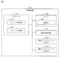
- FIG. The block diagram of the relay device 100 in Embodiment 1.
- FIG. The block diagram of the address management unit 110 in Embodiment 1.
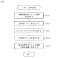
- FIG. The flowchart of the address management process in Embodiment 1.
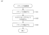
- FIG. The flowchart of the packet relay processing in Embodiment 1.
- FIG. The block diagram of the network system 200 in Embodiment 2.
- FIG. The block diagram of the address in Embodiment 2.
- the flowchart of the next hop address generation processing (S220) in Embodiment 2. The block diagram of the relay device 100 in Embodiment 3.
- the block diagram of the network system 200 (normal state) in Embodiment 3.
- FIG. The block diagram of the network system 200 (at the time of failure) in Embodiment 3.
- Embodiment 1 The network system 200 will be described with reference to FIGS. 1 to 8.
- the network system 200 is a communication system in a network composed of a plurality of subnets (N0 to N3).
- the network system 200 includes a controller 210, a plurality of relay devices (100A to 100C), and a plurality of terminal devices (220A to 220C).
- the relay device (100A to 100C) is not specified, each is referred to as a relay device 100.
- the terminal devices (220A to 220C) are not specified, each is referred to as a terminal device 220.
- the controller 210 is a computer that controls the network system 200, and is connected to the subnet N0.
- the relay device 100 is a communication device that is connected to the upper network and the lower network and relays packets. Specifically, the relay device 100 is a router.
- the relay device 100 includes I / F # 1 and I / F # 2.
- I / F # 1 is connected to the upper network and I / F # 2 is connected to the lower network.
- I / F is an abbreviation for interface.
- the relay device 100A is connected to subnet N0 and subnet N1.
- the upper network in the relay device 100A is subnet N0
- the lower network in the relay device 100A is subnet N1.
- the relay device 100B is connected to subnet N0 and subnet N2.
- the upper network in the relay device 100B is subnet N0
- the lower network in the relay device 100B is subnet N2.
- the relay device 100C is connected to subnet N0 and subnet N3.
- the upper network in the relay device 100C is subnet N0, and the lower network in the relay device 100C is subnet N3.
- the terminal device 220 is a computer connected to the lower network of the relay device 100.
- the terminal device 220A is connected to the subnet N1.
- the terminal device 220B is connected to the subnet N2.
- the terminal device 220C is connected to the subnet N3.
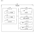
- the configuration of the relay device 100 will be described with reference to FIG.
- the relay device 100 is a computer including hardware such as a processor 101, a memory 102, an auxiliary storage device 103, and a plurality of communication interfaces (104-1, 104-2). These hardware are connected to each other via signal lines.
- the communication interface (104-1, 104-2) is not specified, each is referred to as a communication interface 104.
- the processor 101 is an IC that performs arithmetic processing and controls other hardware.
- the processor 101 is a CPU, DSP or GPU.
- IC is an abbreviation for Integrated Circuit.
- CPU is an abbreviation for Central Processing Unit.
- DSP is an abbreviation for Digital Signal Processor.
- GPU is an abbreviation for Graphics Processing Unit.
- the memory 102 is a volatile storage device.
- the memory 102 is also called a main storage device or a main memory.
- the memory 102 is a RAM.
- the data stored in the memory 102 is stored in the auxiliary storage device 103 as needed.
- RAM is an abbreviation for Random Access Memory.
- the auxiliary storage device 103 is a non-volatile storage device.
- the auxiliary storage device 103 is a ROM, HDD, or flash memory.
- the data stored in the auxiliary storage device 103 is loaded into the memory 102 as needed.
- ROM is an abbreviation for Read Only Memory.
- HDD is an abbreviation for Hard Disk Drive.
- the communication interface 104 is an interface (port) for communication.
- the communication interface 104-1 is referred to as I / F # 1
- the communication interface 104-2 is referred to as I / F # 2.
- the relay device 100 includes elements such as an address management unit 110 and a packet relay unit 120. These elements are realized in software.
- the auxiliary storage device 103 stores a relay program for operating the computer as the address management unit 110 and the packet relay unit 120.
- the relay program is loaded into the memory 102 and executed by the processor 101.
- the OS is further stored in the auxiliary storage device 103. At least a portion of the OS is loaded into memory 102 and executed by processor 101.
- the processor 101 executes a relay program while executing the OS.
- OS is an abbreviation for Operating System.
- the input / output data of the relay program is stored in the storage unit 190.
- the memory 102 functions as a storage unit 190.
- a storage device such as an auxiliary storage device 103, a register in the processor 101, and a cache memory in the processor 101 may function as a storage unit 190 instead of the memory 102 or together with the memory 102.
- the relay device 100 may include a plurality of processors that replace the processor 101.
- the plurality of processors share the role of the processor 101.
- the relay program can be computer-readablely recorded (stored) in a non-volatile recording medium such as a flash memory.
- the configuration of the address management unit 110 will be described with reference to FIG.
- the address management unit 110 includes elements such as an address information acquisition unit 111, an address setting unit 112, a subnet address generation unit 113, and an address information providing unit 114. The functions of these elements will be described later.
- the configuration of the packet relay unit 120 will be described with reference to FIG.
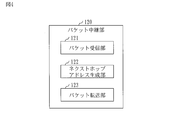
- the packet relay unit 120 includes elements such as a packet reception unit 121, a next hop address generation unit 122, and a packet transfer unit 123. The functions of these elements will be described later.
- the procedure for operating the relay device 100 corresponds to the relay method. Further, the operation procedure of the relay device 100 corresponds to the processing procedure by the relay program.
- address means a communication address.
- IP is an abbreviation for Internet Protocol.
- the address management process will be described with reference to FIG.
- the address management process is a process executed by the address management unit 110 (see FIG. 3).
- step S111 the address information acquisition unit 111 acquires the address information for the relay device 100. Then, the address information acquisition unit 111 stores the address information for the relay device 100 in the storage unit 190.
- the address information for the relay device 100 indicates the address of the relay device 100 in the upper network. This address is referred to as an "upper address".
- the upper address indicates the network address of the upper network, the host address of the relay device 100 in the upper network, and the network mask length.
- the network address is also called the network part, and the host address is also called the host part.
- the network mask length is the length of the network mask and is also called the subnet mask length.
- the network mask is also called the subnet mask.
- step S111 A specific example of step S111 will be described with reference to FIG.
- the controller 210 distributes the address information for the relay device 100A to the relay device 100A.
- DHCP in the IP protocol is well known.
- DHCP is an abbreviation for Dynamic Host Configuration Protocol.
- the address information acquisition unit 111 receives the address information distributed from the controller 210 by I / F # 1.
- the address information for the relay device 100A indicates "192.168.0.2 / 24".
- step S112 the address setting unit 112 extracts the upper address from the address information for the relay device 100, and sets the extracted upper address in I / F # 1.
- step S112 extracts the upper address "192.168.0.2 / 24" from the address information for the relay device 100A, and sets the extracted upper address in I / F # 1.
- step S113 the subnet address generation unit 113 generates a subnet address that is a network address of the lower network based on the address information for the relay device 100. Specifically, the subnet address generation unit 113 replaces the lower-order bit portion of the bit string representing the network address shown in the address information with the bit string representing the host address shown in the address information. The network address obtained by this becomes the subnet address.
- step S113 A specific example of step S113 will be described with reference to FIG.
- the address information for the relay device 100A indicates "192.168.0.2 / 24".
- “192.168.0” is the network address
- “2” is the host address
- “24” is the network mask length.
- the subnet address "192.168.2.0 / 24" is generated.
- the mask length M may be preset in the storage unit 190 or may be acquired as a part of the address information.
- step S114 the address setting unit 112 generates the address of the relay device 100 in the lower network based on the generated subnet address. This address is referred to as a "lower address”.
- the address setting unit 112 sets the generated lower address to I / F # 2.
- the address setting unit 112 selects a host address to be assigned to the relay device 100 from the host address range based on the generated subnet address.
- the address indicating the generated subnet address and the selected host address is the lower address.
- step S114 A specific example of step S114 will be described with reference to FIG.
- the address setting unit 112 selected the host address "1" from the host address range "1 to 255" based on the subnet address "192.168.2.0 / 24". In this case, the lower address of the relay device 100A is "192.168.2.1".
- the address setting unit 112 sets the lower address to I / F # 2.
- step S115 the address information providing unit 114 generates the address information for the terminal device 220 based on the generated subnet address. Then, the address information providing unit 114 provides the address information for the terminal device 220 to the terminal device 220.
- the address information for the terminal device 220 indicates the address of the terminal device 220 in the lower network and the address of the default gateway in the lower network. Specifically, the address information providing unit 114 selects a host address to be assigned to the terminal device 220 from the host address range based on the generated subnet address. The address indicating the generated subnet address and the selected host address is the address of the terminal device 220 in the lower network.
- the default gateway in the lower network is the relay device 100. That is, the address of the default gateway in the lower network is the address of the relay device 100 in the lower network.
- step S115 A specific example of step S115 will be described with reference to FIG.
- the address information providing unit 114 selected the host address "100" from the host host address range "1 to 255" based on the subnet address "192.168.2.0 / 24".
- the address of the terminal device 220A in the subnet N1 is "192.168.2.100/24".
- the lower address of the relay device 100A is "192.168.2.1”.
- the address information providing unit 114 distributes the address information for the terminal device 220 to the terminal device 220A in response to the address distribution request from the terminal device 220A.
- DHCP in the IP protocol is well known.
- the address information for the terminal device 220 indicates "192.168.2.100/24" and "192.168.2.1".
- the terminal device 220A sets "192.168.2.100/24" as the address of the terminal device 220A, and sets "192.168.2.1" as the address of the default gateway.
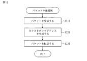
- the packet relay process will be described with reference to FIG. 7.
- the packet relay process is a process executed by the packet relay unit 120.
- step S121 the packet receiving unit 121 receives a packet from the terminal device 220 connected to the lower network to the destination device.
- This destination device is a terminal device connected to a subnet different from the lower network.
- the subnet to which this destination device connects is called a destination subnet.
- the next hop address generation unit 122 generates the next hop address as follows.
- the next hop address is the address of the next hop.
- the next hop is a device identified by the next hop address and is a packet forwarding destination.
- the next hop is connected to the upper network and the destination subnet.
- next hop address generation unit 122 extracts the address of the destination device from the received packet. Specifically, the next hop address generation unit 122 extracts the destination address from the received packet.
- next hop address generation unit 122 extracts the network address of the destination subnet from the address of the destination device. Specifically, the next hop address generation unit 122 extracts the network address from the destination address by using the network mask length shown in the address information for the relay device 100. The extracted network address is the network address of the destination subnet.
- next hop address generator 122 extracts the lower bit portion from the bit string representing the network address of the destination subnet.
- next hop address generation unit 122 generates an address by combining the network address of the upper network with the extracted lower bit portion as the host address.
- the generated address is the next hop address.
- step S123 the packet transfer unit 123 transfers the received packet to the next hop.
- the terminal device 220A transmits the packet P1 destined for the terminal device 220C.
- the subnet N1 network address: 192.168.2
- the subnet N3 network address: 192.168.4
- the terminal device 220A transmits the packet P1 with the default gateway (address: 192.168.2.1) as the next hop.
- the destination address of packet P1, that is, the address of the terminal device 220C is "192.1684.4.100".
- the packet receiving unit 121 receives the packet P1.
- the next hop address generation unit 122 generates the next hop address "192.168.0.4" based on the destination address of the packet P1.
- the packet transfer unit 123 transfers the packet P1 to the relay device 100C identified by the next hop address.
- the relay device 100C receives the packet P1.
- the network address "192.168.4" in the destination address of the packet P1 is the network address of the subnet N3.
- the relay device 100C is connected to the subnet N3. Therefore, the relay device 100C transfers the packet P1 to the terminal device 220C on the subnet N3. Then, the terminal device 220C receives the packet P1.
- the network system 200 can be applied to an air-conditioned network.
- the outdoor unit functions as the relay device 100.
- An address distribution server may be provided in the network system 200. In that case, the address distribution server distributes the address information instead of the controller 210.
- Each relay device 100 can determine the address for the lower network interface (I / F # 2) and the address for the terminal device 220 only by obtaining the address for the upper network interface (I / F # 1). .. Therefore, it is not necessary to individually set the addresses for each relay device 100 and each terminal device 220. Therefore, the setting of each relay device 100 can be simplified.
- the relay device 100 Since the relay device 100 does not need to have a routing table, it is not necessary to perform a process of searching the routing table. However, the relay device 100 can generate the next hop address and forward the packet. That is, the relay device 100 does not require a memory for the routing table, and does not impose a processing load for searching the routing table. Further, since the relay device 100 does not need to exchange route information between the devices in order to construct the routing table, the relay device 100 is not burdened with the processing for exchanging the route information. Therefore, it is possible to reduce the amount of resources required for the relay device 100.
- Embodiment 2 A mode in which the network system 200 is composed of subnets having a plurality of layers will be described mainly different from the first embodiment with reference to FIGS. 9 to 13.
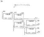
- the configuration of the network system 200 will be described with reference to FIG.
- the network system 200 is layered in a tree shape and is composed of subnets having a plurality of layers. Each relay device 100 is arranged between subnets of two consecutive layers.
- the relay device 100A is arranged between the 0th layer subnet N00 and the 1st layer subnet N01.
- the 0th layer subnet N00 is the upper network
- the 1st layer subnet N01 is the lower network.
- the relay device 100B is arranged between the first layer subnet N01 and the second layer subnet N11.
- the first layer subnet N01 is the upper network
- the second layer subnet N11 is the lower network.
- the relay device 100C is arranged between the first layer subnet N01 and the second layer subnet N10.
- the first layer subnet N01 is the upper network
- the second layer subnet N10 is the lower network.
- the relay device 100D is arranged between the subnet N10 of the second layer and the subnet N21 of the third layer.
- the second layer subnet N10 is the upper network
- the third layer subnet N21 is the lower network.
- the relay device 100E is arranged between the subnet N10 of the second layer and the subnet N22 of the third layer.
- the second layer subnet N10 is the upper network
- the third layer subnet N22 is the lower network.
- each relay device 100 It is the same as the configuration in the first embodiment (see FIGS. 2 to 4).
- the address has a network unit and a host unit.
- the network unit has a network mask length L and indicates the network address of the subnet of each layer.
- the host part indicates the host address of the device belonging to the subnet of each layer.
- the network unit has a common unit and an individual unit.
- the common part indicates a subnet address common to one or more subnets belonging to the same hierarchy.
- the individual part indicates a different subnet address for each subnet belonging to the same hierarchy.
- the mask length corresponding to the entire subnet address (common part + individual part) in the Nth layer is referred to as "individual mask length L_N”.
- the mask length corresponding to the common part of the subnet addresses in the Nth layer is referred to as "common mask length C_N”.
- the individual mask length L_N of the Nth layer is equal to the common mask length C_ (N + 1) of the (N + 1) layer.
- the common mask length C_N of the Nth layer is equal to the individual mask length L_ (N-1) of the (N-1) layer.
- the relay device 100 arranged between the Nth layer and the (N + 1) layer is referred to as the Nth layer relay device 100.
- the storage unit 190 of the relay device 100 of the Nth layer stores mask lengths such as network mask length L, individual mask length L_N, common mask length C_N, and common mask length C_ (N + 1).
- the network mask length L corresponds to the network address length of the upper network, and is stored in the storage unit 190 as a part of the address information.
- Each mask length other than the network mask length L may be stored in the storage unit 190 in advance, or may be stored in the storage unit 190 as a part of the address information.
- Step S210 the packet receiving unit 121 receives the packet.
- Step S210 is the same as step S121 in the first embodiment (see FIG. 7).
- step S220 the next hop address generation unit 122 generates the next hop address.
- next hop address generation process (S220) in the N-layer relay device 100 will be described with reference to FIGS. 12 and 13.
- the next hop address generation unit 122 determines whether the destination network address matches the lower subnet address as follows.
- next hop address generation unit 122 extracts the destination address from the received packet.
- the next hop address generation unit 122 extracts the destination network address from the extracted destination addresses.
- the destination network address is a subnet mask for the upper network, that is, a network address based on the subnet mask having a network mask length L.
- the next hop address generation unit 122 compares the extracted destination network address with the lower subnet address.
- the lower subnet address is the network address of the lower network.
- step S222 If the destination network address matches the lower subnet address, the process proceeds to step S222. If the destination network address does not match the lower subnet address, the process proceeds to step S223.
- step S222 the next hop address generation unit 122 determines the destination address of the received packet as the next hop address. After step S222, the process ends.
- step S223 the next hop address generation unit 122 determines whether the destination network address matches the upper subnet address.
- the destination network address is obtained in step S221.
- the upper subnet address is the network address of the upper network.
- step S224 If the destination network address matches the higher subnet address, the process proceeds to step S224. If the destination network address does not match the higher subnet address, the process proceeds to step S225.
- step S224 the next hop address generation unit 122 determines the destination address of the received packet as the next hop address. After step S224, the process ends.
- step S225 the next hop address generation unit 122 determines whether the Nth layer network address matches the lower layer network address as follows.
- the next hop address generation unit 122 extracts the N-layer network address from the destination address of the received packet.
- the N-layer network address is a network address based on the N-layer subnet mask.
- the Nth layer subnet mask is a subnet mask having an individual mask length L_N.
- the next hop address generation unit 122 extracts the network address based on the Nth layer subnet mask from the subnet address of the lower network.
- the extracted network address is called a lower layer network address.
- the next hop address generation unit 122 compares the Nth layer network address with the lower layer network address.
- step S226 If the Nth layer network address matches the lower layer network address, the process proceeds to step S226. If the Nth layer network address does not match the lower layer network address, the process proceeds to step S227.
- the next hop address generation unit 122 generates the next hop address as follows. First, the next hop address generation unit 122 extracts the (N + 1) layer network address from the destination address of the received packet.
- the first (N + 1) layer network address is a network address based on the (N + 1) layer subnet mask.
- the first (N + 1) layer subnet mask is a subnet mask having an individual mask length L_ (N + 1).
- the next hop address generation unit 122 extracts a lower bit string from the bit string representing the extracted (N + 1) layer network address.
- the lower bit string has the number of bits obtained by "L_ (N + 1) -L_N".
- the host address represented by the extracted lower bit string is referred to as a host address H_ (N + 1).
- the next hop address generation unit 122 generates an address by combining the host address H_ (N + 1) with the lower subnet address.
- the generated address will be the next hop address.
- step S227 the next hop address generation unit 122 determines whether the (N-1) layer network address matches the lower layer network address as follows.
- the next hop address generation unit 122 extracts the (N-1) layer network address from the destination address of the received packet.
- the (N-1) layer network address is a network address based on the (N-1) layer subnet mask.
- the first (N-1) layer subnet mask is a subnet mask having an individual mask length L_ (N-1), that is, a common mask length C_N.
- the next hop address generation unit 122 extracts a network address based on the (N-1) layer subnet mask from the network address of the upper network.
- the extracted network address is called an upper layer network address.
- the next hop address generation unit 122 compares the (N-1) layer network address with the upper layer network address.
- step S228 If the first (N-1) layer network address matches the upper layer network address, the process proceeds to step S228. If the first (N-1) layer network address does not match the upper layer network address, the next hop address is not generated and the process ends.
- step S228, the next hop address generation unit 122 generates the next hop address as follows. First, the next hop address generation unit 122 extracts a lower bit string from the bit string representing the Nth layer network address. The Nth layer network address is extracted in step S225. The lower bit string has the number of bits obtained by "L_N-C_N". The host address represented by the extracted lower bit string is referred to as a host address H_N. Then, the next hop address generation unit 122 generates an address by combining the host address H_N with the upper subnet address. The generated address will be the next hop address. After step S228, the process ends.
- step S230 the packet transfer unit 123 transfers the received packet to the next hop.
- the packet transfer unit 123 operates as follows.
- the packet forwarding unit 123 forwards the packet to the next hop of the lower network.
- the packet transfer unit 123 discards the packet without forwarding it.
- the packet forwarding unit 123 forwards the packet to the next hop of the upper network.
- the packet forwarding unit 123 discards the packet without forwarding it.
- the next hop address is generated in step S226 (see FIG.
- the packet forwarding unit 123 forwards the packet to the next hop of the lower network. However, when the communication interface in which the packet is received is I / F # 2, the packet transfer unit 123 discards the packet without forwarding it.
- the packet transfer unit 123 transfers the packet to the next hop of the upper network. However, when the communication interface in which the packet is received is I / F # 1, the packet forwarding unit 123 discards the packet without forwarding it.
- the packet transfer unit 123 When the next hop address is neither determined nor generated, the packet transfer unit 123 operates as follows. When the relay device 100 is not the relay device of the uppermost layer and the communication interface in which the packet is received is I / F # 2, the packet transfer unit 123 transfers the packet to the default gateway of the upper network. When the relay device 100 is the uppermost relay device, the packet transfer unit 123 discards the packet without forwarding it. When the communication interface in which the packet is received is I / F # 1, the packet forwarding unit 123 discards the packet without forwarding it.
- the network can be layered in a plurality of stages. Therefore, the network system 200 can be configured flexibly in response to the system to which the network system 200 is applied.
- the relay device 100 Since the relay device 100 does not need to have a routing table, it is not necessary to perform a process of searching the routing table. However, the relay device 100 can generate the next hop address and forward the packet. That is, the relay device 100 does not require a memory for the routing table, and does not impose a processing load for searching the routing table. Further, since the relay device 100 does not need to exchange route information between the devices in order to construct the routing table, the relay device 100 is not burdened with the processing for exchanging the route information. Therefore, it is possible to reduce the amount of resources required for the relay device 100.
- Embodiment 3 A form in which the network system 200 is configured to be redundant will be described mainly different from the first embodiment with reference to FIGS. 14 to 16.
- the configuration of the relay device 100 will be described with reference to FIG.
- the relay device 100 further includes a redundancy unit 130.
- the relay program further causes the computer to function as a redundancy unit 130.
- the communication and processing related to redundancy described below are executed by the redundancy unit 130.
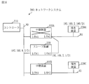
- the configuration of the network system 200 will be described with reference to FIG.
- the network system 200 further includes a slave device 230.
- the configuration of subnet N2 (see FIG. 1) is not shown.
- the slave device 230 is a relay device 100 that is an alternative to the relay device 100A.
- the slave device 230 is connected to the upper network (N0) and the lower network (N1) of the relay device 100A.
- the slave device 230 takes over the address of the relay device 100A and operates in place of the relay device 100A.
- black circles mean that I / F # 1 of the slave device 230A is in an invalid state while the relay device 100A is operating normally.
- the configuration of the slave device 230 is the same as the configuration of each relay device 100 (see FIG. 14).
- the operation of the slave device 230 when the relay device 100A is operating normally will be described with reference to FIG.
- the slave device 230 communicates with the relay device 100A according to the redundancy protocol of the default gateway.
- a specific redundancy protocol is the Virtual Router Redundancy Protocol (VRRP).
- VRRP is standardized by RFC2338.
- the relay device 100A serves as a VRRP master and periodically transmits VRRP packets.
- the slave device 230 receives the VRRP packet.
- the slave device 230 can acquire the address (192.168.2.1 / 24) of the relay device 100A in the lower network (N1).
- the relay device 100A While the relay device 100A is operating normally, the relay process between the subnet N1 and another subnet is performed by the relay device 100A. Further, in order to prevent a loop of relay processing, while the slave device 230 is performing the VRRP backup operation on the lower network (N1), the slave device 230 invalidates I / F # 1 for the upper network (N0). ..
- the slave device 230 becomes a VRRP master by operating according to VRRP in the lower network (N1). Then, the slave device 230 takes over the address (192.168.2.1 / 24) of the relay device 100A in the lower network (N1). At this time, the slave device 230 sets the takeover address to I / F # 2. This address is the default gateway address of the lower network (N1). After that, the slave device 230 assigns the address of the relay device 100A in the upper network (192.168.0.2 / 24) based on the address of the relay device 100A in the lower network (192.168.2.1/24). take over. At this time, the slave device 230 sets the takeover address to I / F # 1. Then, the slave device 230 activates I / F # 1.
- the address of the relay device 100A in the upper network is calculated as follows. First, the slave device 230 extracts the network address of the lower network from the address (192.168.2.1 / 24) of the relay device 100A in the lower network. The extracted network address is "192.168.2". Next, the slave device 230 extracts the lower bit portion from the network address (192.168.2) of the lower network. Specifically, the slave device 230 extracts the lower M bits. The extracted lower M bits are used as the host address. The host address is "2". Then, the slave device 230 combines the network address (192.168.0) of the upper network and the host address (2). The obtained address (192.168.0.2) is the address of the relay device 100A in the upper network.
- the packet is transferred to the slave device 230 by the packet relay process (see FIG. 7) in the relay device 100B. As a result, the packet reaches the terminal device 220A via the slave device 230.
- the network system 200 may be composed of subnets having a plurality of layers, and slave devices 230 may be provided in each subnet.
- Embodiment 3 it is possible to support a redundant network configuration while taking advantage of the feature that the routing table is not managed. Then, it becomes possible to construct a highly reliable network system 200.
- the relay device 100 Since the relay device 100 does not need to have a routing table, it is not necessary to perform a process of searching the routing table. However, the relay device 100 can generate the next hop address and forward the packet. That is, the relay device 100 does not require a memory for the routing table, and does not impose a processing load for searching the routing table. Further, since the relay device 100 does not need to exchange route information between the devices in order to construct the routing table, the relay device 100 is not burdened with the processing for exchanging the route information. Therefore, it is possible to reduce the amount of resources required for the relay device 100.
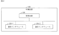
- the relay device 100 includes a processing circuit 109.
- the processing circuit 109 is hardware that realizes the address management unit 110, the packet relay unit 120, and the redundancy unit 130.
- the processing circuit 109 may be dedicated hardware or a processor 101 that executes a program stored in the memory 102.
- the processing circuit 109 is dedicated hardware, the processing circuit 109 is, for example, a single circuit, a composite circuit, a programmed processor, a parallel programmed processor, an ASIC, an FPGA, or a combination thereof.
- ASIC is an abbreviation for Application Specific Integrated Circuit.
- FPGA is an abbreviation for Field Programmable Gate Array.
- the relay device 100 may include a plurality of processing circuits that replace the processing circuit 109.
- the plurality of processing circuits share the functions of the processing circuit 109.
- relay device 100 some functions may be realized by dedicated hardware, and the remaining functions may be realized by software or firmware.
- each function of the relay device 100 can be realized by hardware, software, firmware, or a combination thereof.
- the embodiments are examples of preferred embodiments and are not intended to limit the technical scope of the invention.
- the embodiment may be partially implemented or may be implemented in combination with other embodiments.
- the procedure described using the flowchart or the like may be appropriately changed.
- the "part” which is an element of the relay device 100 may be read as “processing” or "process”.
- 100 relay device 101 processor, 102 memory, 103 auxiliary storage device, 104 communication interface, 109 processing circuit, 110 address management unit, 111 address information acquisition unit, 112 address setting unit, 113 subnet address generation unit, 114 address information provision unit.
Landscapes
- Engineering & Computer Science (AREA)
- Computer Networks & Wireless Communication (AREA)
- Signal Processing (AREA)
- Data Exchanges In Wide-Area Networks (AREA)
- Small-Scale Networks (AREA)
Abstract
中継装置(100A)は、上位ネットワーク(N0)のネットワークアドレスと前記中継装置のホストアドレスとを示すアドレス情報を取得する。前記中継装置は、前記アドレス情報に示されるネットワークアドレスの下位ビット部分を、前記アドレス情報に示されるホストアドレスに置き換えることによって、下位ネットワーク(N1)のネットワークアドレスとなるサブネットアドレスを生成する。前記中継装置は、前記サブネットアドレスに基づくホストアドレス範囲から、端末装置(220A)に割り当てるホストアドレスを選択し、前記サブネットアドレスと選択されたホストアドレスとを示すアドレス情報を前記端末装置に提供する。
Description
本発明は、ネットワークシステムにおける中継装置に関するものである。
空気調和システムなどで用いられている制御ネットワークでは、システム規模の拡大またはシステム機能の増加、に伴う通信量の増大が課題となっている。
また、ネットワークを大規模化するために、ネットワークを分割して階層化する手法が一般に用いられている。IPネットワークにおけるネットワーク分割およびサブネット分割が代表的な例である。IPはInternet Protocolの略称である。
非特許文献1には、IPネットワークに関する技術が記載されている。
また、ネットワークを大規模化するために、ネットワークを分割して階層化する手法が一般に用いられている。IPネットワークにおけるネットワーク分割およびサブネット分割が代表的な例である。IPはInternet Protocolの略称である。
非特許文献1には、IPネットワークに関する技術が記載されている。
空気調和システムにおいても、サブネット分割による大規模化対応が考えられる。
IPネットワークでは、複数のサブネットが中継装置(ルータ)を介して相互に接続される。そして、任意の宛先へのパケットは、各中継装置によって、ルーティングテーブルに基づいてネクストホップへ順次に転送される。これにより、パケットは任意の宛先へ届けられる。
ルーティングテーブルは、ネットワークの数に応じて必要であり、ネクストホップと合わせて学習および登録する必要がある。
IPネットワークでは、複数のサブネットが中継装置(ルータ)を介して相互に接続される。そして、任意の宛先へのパケットは、各中継装置によって、ルーティングテーブルに基づいてネクストホップへ順次に転送される。これにより、パケットは任意の宛先へ届けられる。
ルーティングテーブルは、ネットワークの数に応じて必要であり、ネクストホップと合わせて学習および登録する必要がある。
みやたひろし、"インフラ/ネットワークエンジニアのためのネットワーク技術&設計入門"、SBクリエイティブ株式会社、2013年12月31日
一般のネットワークは、中継専用装置によって相互に接続され、ネットワークシステムを構成する。
空気調和システムでは、従来から、室外機がリピータ中継機能を担って伝送フレームの電気的な中継を行う。そして、ネットワーク分割のために新たな装置を置くことはコスト的に許容されづらい。そこで、室外機がネットワーク中継機能を担うことが求められる。しかし、室外機では、一般的に、組み込み機器のメモリリソースおよびCPUリソースが限られている。そのため、IPルータと同様なネットワーク中継機能を室外機によって実現しようとすると、動的経路交換処理、ルーティングテーブル管理処理および宛先探索処理などにおいてリソースが不足する恐れがある。
空気調和システムでは、従来から、室外機がリピータ中継機能を担って伝送フレームの電気的な中継を行う。そして、ネットワーク分割のために新たな装置を置くことはコスト的に許容されづらい。そこで、室外機がネットワーク中継機能を担うことが求められる。しかし、室外機では、一般的に、組み込み機器のメモリリソースおよびCPUリソースが限られている。そのため、IPルータと同様なネットワーク中継機能を室外機によって実現しようとすると、動的経路交換処理、ルーティングテーブル管理処理および宛先探索処理などにおいてリソースが不足する恐れがある。
本発明は、限られたリソースでネットワーク中継機能を実現することを目的とする。
本発明の中継装置は、上位ネットワークと下位ネットワークとに接続されてパケットを中継する。
前記中継装置は、
前記上位ネットワークのネットワークアドレスと前記上位ネットワークにおける前記中継装置のホストアドレスとを示すアドレス情報を取得するアドレス情報取得部と、
取得されたアドレス情報に示されるネットワークアドレスを表すビット列のうちの下位ビット部分を、取得されたアドレス情報に示されるホストアドレスを表すビット列に置き換えることによって、前記下位ネットワークのネットワークアドレスとなるサブネットアドレスを生成するサブネットアドレス生成部と、を備える。
前記中継装置は、
前記上位ネットワークのネットワークアドレスと前記上位ネットワークにおける前記中継装置のホストアドレスとを示すアドレス情報を取得するアドレス情報取得部と、
取得されたアドレス情報に示されるネットワークアドレスを表すビット列のうちの下位ビット部分を、取得されたアドレス情報に示されるホストアドレスを表すビット列に置き換えることによって、前記下位ネットワークのネットワークアドレスとなるサブネットアドレスを生成するサブネットアドレス生成部と、を備える。
本発明によれば、動的経路交換処理、ルーティングテーブル管理処理または宛先探索処理などの従来の処理を行わずに、上位ネットワークにおけるアドレス情報に基づいて下位ネットワークのサブネットアドレスを得ることができる。そのため、限られたリソースでネットワーク中継機能を実現することが可能となる。
実施の形態および図面において、同じ要素または対応する要素には同じ符号を付している。説明した要素と同じ符号が付された要素の説明は適宜に省略または簡略化する。図中の矢印はデータの流れ又は処理の流れを主に示している。
実施の形態1.
ネットワークシステム200について、図1から図8に基づいて説明する。
ネットワークシステム200について、図1から図8に基づいて説明する。
***構成の説明***
図1に基づいて、ネットワークシステム200の構成を説明する。
ネットワークシステム200は、複数のサブネット(N0~N3)で構成されるネットワークにおける通信システムである。
ネットワークシステム200は、コントローラ210と複数の中継装置(100A~100C)と複数の端末装置(220A~220C)とを備える。
中継装置(100A~100C)を特定しない場合、それぞれを中継装置100と称する。
端末装置(220A~220C)を特定しない場合、それぞれを端末装置220と称する。
図1に基づいて、ネットワークシステム200の構成を説明する。
ネットワークシステム200は、複数のサブネット(N0~N3)で構成されるネットワークにおける通信システムである。
ネットワークシステム200は、コントローラ210と複数の中継装置(100A~100C)と複数の端末装置(220A~220C)とを備える。
中継装置(100A~100C)を特定しない場合、それぞれを中継装置100と称する。
端末装置(220A~220C)を特定しない場合、それぞれを端末装置220と称する。
コントローラ210は、ネットワークシステム200を制御するコンピュータであり、サブネットN0に接続される。
中継装置100は、上位ネットワークと下位ネットワークとに接続されてパケットを中継する通信装置である。具体的には、中継装置100はルータである。
中継装置100は、I/F#1とI/F#2を備える。I/F#1は上位ネットワークに接続され、I/F#2は下位ネットワークに接続される。I/Fはインタフェースの略称である。
中継装置100は、I/F#1とI/F#2を備える。I/F#1は上位ネットワークに接続され、I/F#2は下位ネットワークに接続される。I/Fはインタフェースの略称である。
中継装置100Aは、サブネットN0とサブネットN1とに接続されている。中継装置100Aにおける上位ネットワークがサブネットN0であり、中継装置100Aにおける下位ネットワークがサブネットN1である。
中継装置100Bは、サブネットN0とサブネットN2とに接続されている。中継装置100Bにおける上位ネットワークがサブネットN0であり、中継装置100Bにおける下位ネットワークがサブネットN2である。
中継装置100Cは、サブネットN0とサブネットN3とに接続されている。中継装置100Cにおける上位ネットワークがサブネットN0であり、中継装置100Cにおける下位ネットワークがサブネットN3である。
中継装置100Bは、サブネットN0とサブネットN2とに接続されている。中継装置100Bにおける上位ネットワークがサブネットN0であり、中継装置100Bにおける下位ネットワークがサブネットN2である。
中継装置100Cは、サブネットN0とサブネットN3とに接続されている。中継装置100Cにおける上位ネットワークがサブネットN0であり、中継装置100Cにおける下位ネットワークがサブネットN3である。
端末装置220は、中継装置100の下位ネットワークに接続されたコンピュータである。
端末装置220Aは、サブネットN1に接続されている。
端末装置220Bは、サブネットN2に接続されている。
端末装置220Cは、サブネットN3に接続されている。
端末装置220Aは、サブネットN1に接続されている。
端末装置220Bは、サブネットN2に接続されている。
端末装置220Cは、サブネットN3に接続されている。
図2に基づいて、中継装置100の構成を説明する。
中継装置100は、プロセッサ101とメモリ102と補助記憶装置103と複数の通信インタフェース(104-1、104-2)といったハードウェアを備えるコンピュータである。これらのハードウェアは、信号線を介して互いに接続されている。
通信インタフェース(104-1、104-2)を特定しない場合、それぞれを通信インタフェース104と称する。
中継装置100は、プロセッサ101とメモリ102と補助記憶装置103と複数の通信インタフェース(104-1、104-2)といったハードウェアを備えるコンピュータである。これらのハードウェアは、信号線を介して互いに接続されている。
通信インタフェース(104-1、104-2)を特定しない場合、それぞれを通信インタフェース104と称する。
プロセッサ101は、演算処理を行うICであり、他のハードウェアを制御する。例えば、プロセッサ101は、CPU、DSPまたはGPUである。
ICは、Integrated Circuitの略称である。
CPUは、Central Processing Unitの略称である。
DSPは、Digital Signal Processorの略称である。
GPUは、Graphics Processing Unitの略称である。
ICは、Integrated Circuitの略称である。
CPUは、Central Processing Unitの略称である。
DSPは、Digital Signal Processorの略称である。
GPUは、Graphics Processing Unitの略称である。
メモリ102は揮発性の記憶装置である。メモリ102は、主記憶装置またはメインメモリとも呼ばれる。例えば、メモリ102はRAMである。メモリ102に記憶されたデータは必要に応じて補助記憶装置103に保存される。
RAMは、Random Access Memoryの略称である。
RAMは、Random Access Memoryの略称である。
補助記憶装置103は不揮発性の記憶装置である。例えば、補助記憶装置103は、ROM、HDDまたはフラッシュメモリである。補助記憶装置103に記憶されたデータは必要に応じてメモリ102にロードされる。
ROMは、Read Only Memoryの略称である。
HDDは、Hard Disk Driveの略称である。
ROMは、Read Only Memoryの略称である。
HDDは、Hard Disk Driveの略称である。
通信インタフェース104は通信用のインタフェース(ポート)である。
通信インタフェース104-1をI/F#1と記し、通信インタフェース104-2をI/F#2と記す。
通信インタフェース104-1をI/F#1と記し、通信インタフェース104-2をI/F#2と記す。
中継装置100は、アドレス管理部110とパケット中継部120といった要素を備える。これらの要素はソフトウェアで実現される。
補助記憶装置103には、アドレス管理部110とパケット中継部120としてコンピュータを機能させるための中継プログラムが記憶されている。中継プログラムは、メモリ102にロードされて、プロセッサ101によって実行される。
補助記憶装置103には、さらに、OSが記憶されている。OSの少なくとも一部は、メモリ102にロードされて、プロセッサ101によって実行される。
プロセッサ101は、OSを実行しながら、中継プログラムを実行する。
OSは、Operating Systemの略称である。
補助記憶装置103には、さらに、OSが記憶されている。OSの少なくとも一部は、メモリ102にロードされて、プロセッサ101によって実行される。
プロセッサ101は、OSを実行しながら、中継プログラムを実行する。
OSは、Operating Systemの略称である。
中継プログラムの入出力データは記憶部190に記憶される。
メモリ102は記憶部190として機能する。但し、補助記憶装置103、プロセッサ101内のレジスタおよびプロセッサ101内のキャッシュメモリなどの記憶装置が、メモリ102の代わりに、又は、メモリ102と共に、記憶部190として機能してもよい。
メモリ102は記憶部190として機能する。但し、補助記憶装置103、プロセッサ101内のレジスタおよびプロセッサ101内のキャッシュメモリなどの記憶装置が、メモリ102の代わりに、又は、メモリ102と共に、記憶部190として機能してもよい。
中継装置100は、プロセッサ101を代替する複数のプロセッサを備えてもよい。複数のプロセッサは、プロセッサ101の役割を分担する。
中継プログラムは、フラッシュメモリのような不揮発性の記録媒体にコンピュータ読み取り可能に記録(格納)することができる。
図3に基づいて、アドレス管理部110の構成を説明する。
アドレス管理部110は、アドレス情報取得部111とアドレス設定部112とサブネットアドレス生成部113とアドレス情報提供部114といった要素を備える。これら要素の機能について後述する。
アドレス管理部110は、アドレス情報取得部111とアドレス設定部112とサブネットアドレス生成部113とアドレス情報提供部114といった要素を備える。これら要素の機能について後述する。
図4に基づいて、パケット中継部120の構成を説明する。
パケット中継部120は、パケット受信部121とネクストホップアドレス生成部122とパケット転送部123といった要素を備える。これら要素の機能について後述する。
パケット中継部120は、パケット受信部121とネクストホップアドレス生成部122とパケット転送部123といった要素を備える。これら要素の機能について後述する。
***動作の説明***
中継装置100の動作の手順は中継方法に相当する。また、中継装置100の動作の手順は中継プログラムによる処理の手順に相当する。
中継装置100の動作の手順は中継方法に相当する。また、中継装置100の動作の手順は中継プログラムによる処理の手順に相当する。
特に指定しない場合、「アドレス」は通信アドレスを意味する。具体的な通信アドレスの例はIPアドレスである。IPはInternet Protocolの略称である。
図5に基づいて、アドレス管理処理を説明する。
アドレス管理処理は、アドレス管理部110(図3参照)によって実行される処理である。
アドレス管理処理は、アドレス管理部110(図3参照)によって実行される処理である。
ステップS111において、アドレス情報取得部111は、中継装置100用のアドレス情報を取得する。
そして、アドレス情報取得部111は、中継装置100用のアドレス情報を記憶部190に保存する。
そして、アドレス情報取得部111は、中継装置100用のアドレス情報を記憶部190に保存する。
中継装置100用のアドレス情報は、上位ネットワークにおける中継装置100のアドレスを示す。このアドレスを「上位側アドレス」と称する。
上位側アドレスは、上位ネットワークのネットワークアドレスと、上位ネットワークにおける中継装置100のホストアドレスと、ネットワークマスク長を示す。
ネットワークアドレスはネットワーク部ともいい、ホストアドレスはホスト部ともいう。
ネットワークマスク長は、ネットワークマスクの長さであり、サブネットマスク長ともいう。ネットワークマスクはサブネットマスクともいう。
上位側アドレスは、上位ネットワークのネットワークアドレスと、上位ネットワークにおける中継装置100のホストアドレスと、ネットワークマスク長を示す。
ネットワークアドレスはネットワーク部ともいい、ホストアドレスはホスト部ともいう。
ネットワークマスク長は、ネットワークマスクの長さであり、サブネットマスク長ともいう。ネットワークマスクはサブネットマスクともいう。
図6に基づいて、ステップS111の具体例を説明する。
コントローラ210は、中継装置100A用のアドレス情報を中継装置100Aへ配布する。配布方法としては、IPプロトコルにおけるDHCPが良く知られている。DHCPはDynamic Host Configuration Protocolの略称である。
アドレス情報取得部111は、コントローラ210から配布されたアドレス情報をI/F#1によって受信する。
中継装置100A用のアドレス情報は「192.168.0.2/24」を示す。
コントローラ210は、中継装置100A用のアドレス情報を中継装置100Aへ配布する。配布方法としては、IPプロトコルにおけるDHCPが良く知られている。DHCPはDynamic Host Configuration Protocolの略称である。
アドレス情報取得部111は、コントローラ210から配布されたアドレス情報をI/F#1によって受信する。
中継装置100A用のアドレス情報は「192.168.0.2/24」を示す。
図5に戻り、ステップS112から説明を続ける。
ステップS112において、アドレス設定部112は、中継装置100用のアドレス情報から上位側アドレスを抽出し、抽出した上位側アドレスをI/F#1に設定する。
ステップS112において、アドレス設定部112は、中継装置100用のアドレス情報から上位側アドレスを抽出し、抽出した上位側アドレスをI/F#1に設定する。
図6に基づいて、ステップS112の具体例を説明する。
アドレス設定部112は、中継装置100A用のアドレス情報から上位側アドレス「192.168.0.2/24」を抽出し、抽出した上位側アドレスをI/F#1に設定する。
アドレス設定部112は、中継装置100A用のアドレス情報から上位側アドレス「192.168.0.2/24」を抽出し、抽出した上位側アドレスをI/F#1に設定する。
図5に戻り、ステップS113から説明を続ける。
ステップS113において、サブネットアドレス生成部113は、中継装置100用のアドレス情報に基づいて、下位ネットワークのネットワークアドレスとなるサブネットアドレスを生成する。
具体的には、サブネットアドレス生成部113は、アドレス情報に示されるネットワークアドレスを表すビット列のうちの下位ビット部分を、アドレス情報に示されるホストアドレスを表すビット列に置き換える。これによって得られるネットワークアドレスがサブネットアドレスとなる。
ステップS113において、サブネットアドレス生成部113は、中継装置100用のアドレス情報に基づいて、下位ネットワークのネットワークアドレスとなるサブネットアドレスを生成する。
具体的には、サブネットアドレス生成部113は、アドレス情報に示されるネットワークアドレスを表すビット列のうちの下位ビット部分を、アドレス情報に示されるホストアドレスを表すビット列に置き換える。これによって得られるネットワークアドレスがサブネットアドレスとなる。
図6に基づいて、ステップS113の具体例を説明する。
中継装置100A用のアドレス情報は「192.168.0.2/24」を示す。「192.168.0」がネットワークアドレスであり、「2」がホストアドレスであり、「24」がネットワークマスク長である。
サブネットアドレス生成部113は、ネットワークアドレス「192.168.0」の下位Mビットをホストアドレス「2」を表すビット列に置き換える。この例ではM=8である。その結果、「192.168.2.0/24」というサブネットアドレスが生成される。
マスク長Mは、記憶部190に予め設定されてもよいし、アドレス情報の一部として取得されてもよい。
中継装置100A用のアドレス情報は「192.168.0.2/24」を示す。「192.168.0」がネットワークアドレスであり、「2」がホストアドレスであり、「24」がネットワークマスク長である。
サブネットアドレス生成部113は、ネットワークアドレス「192.168.0」の下位Mビットをホストアドレス「2」を表すビット列に置き換える。この例ではM=8である。その結果、「192.168.2.0/24」というサブネットアドレスが生成される。
マスク長Mは、記憶部190に予め設定されてもよいし、アドレス情報の一部として取得されてもよい。
ステップS114において、アドレス設定部112は、生成されたサブネットアドレスに基づいて、下位ネットワークにおける中継装置100のアドレスを生成する。このアドレスを「下位側アドレス」と称する。
アドレス設定部112は、生成した下位側アドレスをI/F#2に設定する。
アドレス設定部112は、生成した下位側アドレスをI/F#2に設定する。
具体的には、アドレス設定部112は、生成されたサブネットアドレスに基づくホストアドレス範囲から、中継装置100に割り当てるホストアドレスを選択する。
生成されたサブネットアドレスと選択されたホストアドレスとを示すアドレスが下位側アドレスである。
生成されたサブネットアドレスと選択されたホストアドレスとを示すアドレスが下位側アドレスである。
図6に基づいて、ステップS114の具体例を説明する。
アドレス設定部112は、サブネットアドレス「192.168.2.0/24」に基づくホストアドレス範囲「1~255」からホストアドレス「1」を選択した。この場合、中継装置100Aの下位側アドレスは「192.168.2.1」である。
アドレス設定部112は、下位側アドレスをI/F#2に設定する。
アドレス設定部112は、サブネットアドレス「192.168.2.0/24」に基づくホストアドレス範囲「1~255」からホストアドレス「1」を選択した。この場合、中継装置100Aの下位側アドレスは「192.168.2.1」である。
アドレス設定部112は、下位側アドレスをI/F#2に設定する。
図5に戻り、ステップS115を説明する。
ステップS115において、アドレス情報提供部114は、生成されたサブネットアドレスに基づいて、端末装置220用のアドレス情報を生成する。
そして、アドレス情報提供部114は、端末装置220用のアドレス情報を端末装置220へ提供する。
ステップS115において、アドレス情報提供部114は、生成されたサブネットアドレスに基づいて、端末装置220用のアドレス情報を生成する。
そして、アドレス情報提供部114は、端末装置220用のアドレス情報を端末装置220へ提供する。
端末装置220用のアドレス情報は、下位ネットワークにおける端末装置220のアドレスと、下位ネットワークにおけるデフォルトゲートウェイのアドレスを示す。
具体的には、アドレス情報提供部114は、生成されたサブネットアドレスに基づくホストアドレス範囲から、端末装置220に割り当てるホストアドレスを選択する。
生成されたサブネットアドレスと選択されたホストアドレスとを示すアドレスが、下位ネットワークにおける端末装置220のアドレスである。
下位ネットワークにおけるデフォルトゲートウェイは、中継装置100である。つまり、下位ネットワークにおけるデフォルトゲートウェイのアドレスは、下位ネットワークにおける中継装置100のアドレスである。
具体的には、アドレス情報提供部114は、生成されたサブネットアドレスに基づくホストアドレス範囲から、端末装置220に割り当てるホストアドレスを選択する。
生成されたサブネットアドレスと選択されたホストアドレスとを示すアドレスが、下位ネットワークにおける端末装置220のアドレスである。
下位ネットワークにおけるデフォルトゲートウェイは、中継装置100である。つまり、下位ネットワークにおけるデフォルトゲートウェイのアドレスは、下位ネットワークにおける中継装置100のアドレスである。
図6に基づいて、ステップS115の具体例を説明する。
アドレス情報提供部114は、サブネットアドレス「192.168.2.0/24」に基づくホストホストアドレス範囲「1~255」からホストアドレス「100」を選択した。この場合、サブネットN1における端末装置220Aのアドレスは「192.168.2.100/24」である。また、中継装置100Aの下位側アドレスは「192.168.2.1」である。
アドレス情報提供部114は、端末装置220Aからのアドレス配布要求に応じて、端末装置220用のアドレス情報を端末装置220Aに配布する。配布方法としては、IPプロトコルにおけるDHCPが良く知られている。
端末装置220用のアドレス情報は、「192.168.2.100/24」と「192.168.2.1」を示す。
端末装置220Aは、「192.168.2.100/24」を端末装置220Aのアドレスとして設定し、「192.168.2.1」をデフォルトゲートウェイのアドレスとして設定する。
アドレス情報提供部114は、サブネットアドレス「192.168.2.0/24」に基づくホストホストアドレス範囲「1~255」からホストアドレス「100」を選択した。この場合、サブネットN1における端末装置220Aのアドレスは「192.168.2.100/24」である。また、中継装置100Aの下位側アドレスは「192.168.2.1」である。
アドレス情報提供部114は、端末装置220Aからのアドレス配布要求に応じて、端末装置220用のアドレス情報を端末装置220Aに配布する。配布方法としては、IPプロトコルにおけるDHCPが良く知られている。
端末装置220用のアドレス情報は、「192.168.2.100/24」と「192.168.2.1」を示す。
端末装置220Aは、「192.168.2.100/24」を端末装置220Aのアドレスとして設定し、「192.168.2.1」をデフォルトゲートウェイのアドレスとして設定する。
図7に基づいて、パケット中継処理を説明する。
パケット中継処理は、パケット中継部120によって実行される処理である。
パケット中継処理は、パケット中継部120によって実行される処理である。
ステップS121において、パケット受信部121は、下位ネットワークに接続する端末装置220から、宛先装置へのパケットを受信する。
この宛先装置は、下位ネットワークとは異なるサブネットに接続する端末装置である。
この宛先装置が接続するサブネットを宛先サブネットと称する。
この宛先装置は、下位ネットワークとは異なるサブネットに接続する端末装置である。
この宛先装置が接続するサブネットを宛先サブネットと称する。
ステップS122において、ネクストホップアドレス生成部122は、ネクストホップアドレスを以下のように生成する。
ネクストホップアドレスは、ネクストホップのアドレスである。
ネクストホップは、ネクストホップアドレスで識別される装置であり、パケットの転送先となる。ネクストホップは、上位ネットワークと宛先サブネットとに接続されている。
ネクストホップアドレスは、ネクストホップのアドレスである。
ネクストホップは、ネクストホップアドレスで識別される装置であり、パケットの転送先となる。ネクストホップは、上位ネットワークと宛先サブネットとに接続されている。
まず、ネクストホップアドレス生成部122は、受信されたパケットから、宛先装置のアドレスを抽出する。
具体的には、ネクストホップアドレス生成部122は、受信されたパケットから、宛先アドレスを抽出する。
具体的には、ネクストホップアドレス生成部122は、受信されたパケットから、宛先アドレスを抽出する。
次に、ネクストホップアドレス生成部122は、宛先装置のアドレスから宛先サブネットのネットワークアドレスを抽出する。
具体的には、ネクストホップアドレス生成部122は、中継装置100用のアドレス情報に示されるネットワークマスク長を用いて、宛先アドレスからネットワークアドレスを抽出する。抽出されるネットワークアドレスが宛先サブネットのネットワークアドレスである。
具体的には、ネクストホップアドレス生成部122は、中継装置100用のアドレス情報に示されるネットワークマスク長を用いて、宛先アドレスからネットワークアドレスを抽出する。抽出されるネットワークアドレスが宛先サブネットのネットワークアドレスである。
次に、ネクストホップアドレス生成部122は、宛先サブネットのネットワークアドレスを表すビット列から下位ビット部分を抽出する。
そして、ネクストホップアドレス生成部122は、上位ネットワークのネットワークアドレスに、抽出された下位ビット部分をホストアドレスとして組み合わせて、アドレスを生成する。生成されるアドレスが、ネクストホップアドレスである。
ステップS123において、パケット転送部123は、受信されたパケットをネクストホップへ転送する。
図8に基づいて、パケット中継処理の具体例を説明する。
端末装置220Aが、端末装置220Cを宛先とするパケットP1を送信するものとする。
端末装置220Aが属するサブネットN1(ネットワークアドレス:192.168.2)は、端末装置220Cが属するサブネットN3(ネットワークアドレス:192.168.4)と異なる。そのため、端末装置220Aは、デフォルトゲートウェイ(アドレス:192.168.2.1)をネクストホップにして、パケットP1を送信する。パケットP1の宛先アドレス、すなわち、端末装置220Cのアドレスは「192.168.4.100」である。
パケット受信部121は、パケットP1を受信する。
ネクストホップアドレス生成部122は、パケットP1の宛先アドレスに基づいて、ネクストホップアドレス「192.168.0.4」を生成する。
パケット転送部123は、ネクストホップアドレスで識別される中継装置100Cへ、パケットP1を転送する。
中継装置100Cは、パケットP1を受信する。パケットP1の宛先アドレスにおけるネットワークアドレス「192.168.4」はサブネットN3のネットワークアドレスである。中継装置100CはサブネットN3に接続されている。そのため、中継装置100Cは、サブネットN3の端末装置220Cへ、パケットP1を転送する。
そして、端末装置220CがパケットP1を受信する。
端末装置220Aが、端末装置220Cを宛先とするパケットP1を送信するものとする。
端末装置220Aが属するサブネットN1(ネットワークアドレス:192.168.2)は、端末装置220Cが属するサブネットN3(ネットワークアドレス:192.168.4)と異なる。そのため、端末装置220Aは、デフォルトゲートウェイ(アドレス:192.168.2.1)をネクストホップにして、パケットP1を送信する。パケットP1の宛先アドレス、すなわち、端末装置220Cのアドレスは「192.168.4.100」である。
パケット受信部121は、パケットP1を受信する。
ネクストホップアドレス生成部122は、パケットP1の宛先アドレスに基づいて、ネクストホップアドレス「192.168.0.4」を生成する。
パケット転送部123は、ネクストホップアドレスで識別される中継装置100Cへ、パケットP1を転送する。
中継装置100Cは、パケットP1を受信する。パケットP1の宛先アドレスにおけるネットワークアドレス「192.168.4」はサブネットN3のネットワークアドレスである。中継装置100CはサブネットN3に接続されている。そのため、中継装置100Cは、サブネットN3の端末装置220Cへ、パケットP1を転送する。
そして、端末装置220CがパケットP1を受信する。
ネクストホップアドレス生成部122は、ネクストホップアドレス「192.168.0.4」を以下のように生成する。
まず、ネクストホップアドレス生成部122は、ネットワークマスク長「24」を用いて、パケットP1の宛先アドレス「192.168.4.100」からネットワークアドレス「192.168.4」を抽出する。
次に、ネクストホップアドレス生成部122は、マスク長Mを用いて、ネットワークアドレス「192.168.4」の下位Mビットを抽出する。この例ではM=8である。つまり、ネクストホップアドレス生成部122は、下位Mビットで表される「4」を抽出する。マスク長Mは記憶部190に記憶されている。
そして、ネクストホップアドレス生成部122は、サブネットN0のネットワークアドレス「192.168.0」に、宛先アドレスのネットワークアドレスから抽出された「4」をホストアドレスとして組み合わせる。
これにより、ネクストホップアドレス「192.168.0.4」が生成される。
まず、ネクストホップアドレス生成部122は、ネットワークマスク長「24」を用いて、パケットP1の宛先アドレス「192.168.4.100」からネットワークアドレス「192.168.4」を抽出する。
次に、ネクストホップアドレス生成部122は、マスク長Mを用いて、ネットワークアドレス「192.168.4」の下位Mビットを抽出する。この例ではM=8である。つまり、ネクストホップアドレス生成部122は、下位Mビットで表される「4」を抽出する。マスク長Mは記憶部190に記憶されている。
そして、ネクストホップアドレス生成部122は、サブネットN0のネットワークアドレス「192.168.0」に、宛先アドレスのネットワークアドレスから抽出された「4」をホストアドレスとして組み合わせる。
これにより、ネクストホップアドレス「192.168.0.4」が生成される。
***実施例の説明***
ネットワークシステム200は、空気調和ネットワークに適用することができる。その場合、室外機が中継装置100として機能することとなる。
ネットワークシステム200は、空気調和ネットワークに適用することができる。その場合、室外機が中継装置100として機能することとなる。
ネットワークシステム200にアドレス配布サーバを設けてもよい。その場合、アドレス配布サーバが、コントローラ210の代わりに、アドレス情報を配布することとなる。
***実施の形態1の効果***
各中継装置100は、上位ネットワークインタフェース(I/F#1)用のアドレスを得るだけで、下位ネットワークインタフェース(I/F#2)用のアドレスおよび端末装置220用のアドレスを決定することができる。そのため、各中継装置100と各端末装置220とに対して、個別にアドレス設定を行う必要が無い。したがって、各中継装置100の設定を簡素化することができる。
各中継装置100は、上位ネットワークインタフェース(I/F#1)用のアドレスを得るだけで、下位ネットワークインタフェース(I/F#2)用のアドレスおよび端末装置220用のアドレスを決定することができる。そのため、各中継装置100と各端末装置220とに対して、個別にアドレス設定を行う必要が無い。したがって、各中継装置100の設定を簡素化することができる。
中継装置100は、ルーティングテーブルを持つ必要がないため、ルーティングテーブルを検索する処理を行う必要もない。しかし、中継装置100は、ネクストホップのアドレスを生成してパケットを転送することが可能である。
つまり、中継装置100には、ルーティングテーブルのためのメモリが不要であり、且つ、ルーティングテーブルを検索するための処理の負荷がかからない。さらに、中継装置100はルーティングテーブルを構築するために装置間で経路情報を交換する必要もないため、中継装置100には経路情報を交換するための処理の負荷もかからない。したがって、中継装置100に必要なリソースの量を削減することが可能である。
つまり、中継装置100には、ルーティングテーブルのためのメモリが不要であり、且つ、ルーティングテーブルを検索するための処理の負荷がかからない。さらに、中継装置100はルーティングテーブルを構築するために装置間で経路情報を交換する必要もないため、中継装置100には経路情報を交換するための処理の負荷もかからない。したがって、中継装置100に必要なリソースの量を削減することが可能である。
実施の形態2.
ネットワークシステム200が複数階層のサブネットで構成された形態について、主に実施の形態1と異なる点を図9から図13に基づいて説明する。
ネットワークシステム200が複数階層のサブネットで構成された形態について、主に実施の形態1と異なる点を図9から図13に基づいて説明する。
***構成の説明***
図9に基づいて、ネットワークシステム200の構成を説明する。
ネットワークシステム200は、ツリー状に階層化され、複数階層のサブネットで構成される。
各中継装置100は、連続する2つの階層のサブネット間に配置される。
図9に基づいて、ネットワークシステム200の構成を説明する。
ネットワークシステム200は、ツリー状に階層化され、複数階層のサブネットで構成される。
各中継装置100は、連続する2つの階層のサブネット間に配置される。
中継装置100Aは、第0層のサブネットN00と第1層のサブネットN01との間に配置されている。第0層のサブネットN00が上位ネットワークであり、第1層のサブネットN01が下位ネットワークである。
中継装置100Bは、第1層のサブネットN01と第2層のサブネットN11との間に配置されている。第1層のサブネットN01が上位ネットワークであり、第2層のサブネットN11が下位ネットワークである。
中継装置100Cは、第1層のサブネットN01と第2層のサブネットN10との間に配置されている。第1層のサブネットN01が上位ネットワークであり、第2層のサブネットN10が下位ネットワークである。
中継装置100Dは、第2層のサブネットN10と第3層のサブネットN21との間に配置されている。第2層のサブネットN10が上位ネットワークであり、第3層のサブネットN21が下位ネットワークである。
中継装置100Eは、第2層のサブネットN10と第3層のサブネットN22との間に配置されている。第2層のサブネットN10が上位ネットワークであり、第3層のサブネットN22が下位ネットワークである。
中継装置100Bは、第1層のサブネットN01と第2層のサブネットN11との間に配置されている。第1層のサブネットN01が上位ネットワークであり、第2層のサブネットN11が下位ネットワークである。
中継装置100Cは、第1層のサブネットN01と第2層のサブネットN10との間に配置されている。第1層のサブネットN01が上位ネットワークであり、第2層のサブネットN10が下位ネットワークである。
中継装置100Dは、第2層のサブネットN10と第3層のサブネットN21との間に配置されている。第2層のサブネットN10が上位ネットワークであり、第3層のサブネットN21が下位ネットワークである。
中継装置100Eは、第2層のサブネットN10と第3層のサブネットN22との間に配置されている。第2層のサブネットN10が上位ネットワークであり、第3層のサブネットN22が下位ネットワークである。
各中継装置100の構成は。実施の形態1における構成と同じである(図2から図4を参照)。
図10に基づいて、アドレスの構成を説明する。
アドレスは、ネットワーク部とホスト部とを有する。
ネットワーク部は、ネットワークマスク長Lを有し、各階層のサブネットのネットワークアドレスを示す。
ホスト部は、各階層のサブネットに属する装置のホストアドレスを示す。
アドレスは、ネットワーク部とホスト部とを有する。
ネットワーク部は、ネットワークマスク長Lを有し、各階層のサブネットのネットワークアドレスを示す。
ホスト部は、各階層のサブネットに属する装置のホストアドレスを示す。
ネットワーク部は、共通部と個別部とを有する。
共通部は、同じ階層に属する1つ以上のサブネットに共通するサブネットアドレスを示す。
個別部は、同じ階層に属するサブネット毎に異なるサブネットアドレスを示す。
共通部は、同じ階層に属する1つ以上のサブネットに共通するサブネットアドレスを示す。
個別部は、同じ階層に属するサブネット毎に異なるサブネットアドレスを示す。
第N層におけるサブネットアドレスの全体(共通部+個別部)に対応するマスク長を「個別マスク長L_N」と称する。
第N層におけるサブネットアドレスのうちの共通部に対応するマスク長を「共通マスク長C_N」と称する。
第N層におけるサブネットアドレスのうちの共通部に対応するマスク長を「共通マスク長C_N」と称する。
第N層の個別マスク長L_Nは、第(N+1)層の共通マスク長C_(N+1)と等しい。
第N層の共通マスク長C_Nは、第(N-1)層の個別マスク長L_(N-1)と等しい。
第N層の共通マスク長C_Nは、第(N-1)層の個別マスク長L_(N-1)と等しい。
第N層と第(N+1)層との間に配置される中継装置100を第N層の中継装置100と称する。
第N層の中継装置100の記憶部190には、ネットワークマスク長Lと個別マスク長L_Nと共通マスク長C_Nと共通マスク長C_(N+1)といったマスク長が記憶される。
ネットワークマスク長Lは、上位ネットワークのネットワークアドレス長に相当し、アドレス情報の一部として記憶部190に記憶される。
ネットワークマスク長L以外の各マスク長は、記憶部190に予め記憶されてもよいし、アドレス情報の一部として記憶部190に記憶されてもよい。
第N層の中継装置100の記憶部190には、ネットワークマスク長Lと個別マスク長L_Nと共通マスク長C_Nと共通マスク長C_(N+1)といったマスク長が記憶される。
ネットワークマスク長Lは、上位ネットワークのネットワークアドレス長に相当し、アドレス情報の一部として記憶部190に記憶される。
ネットワークマスク長L以外の各マスク長は、記憶部190に予め記憶されてもよいし、アドレス情報の一部として記憶部190に記憶されてもよい。
***動作の説明***
アドレス管理処理は、実施の形態1における処理と同じである(図5参照)。
アドレス管理処理は、実施の形態1における処理と同じである(図5参照)。
図11に基づいて、パケット中継処理を説明する。
ステップS210において、パケット受信部121はパケットを受信する。
ステップS210は、実施の形態1におけるステップS121と同じである(図7参照)。
ステップS210において、パケット受信部121はパケットを受信する。
ステップS210は、実施の形態1におけるステップS121と同じである(図7参照)。
ステップS220において、ネクストホップアドレス生成部122は、ネクストホップアドレスを生成する。
図12および図13に基づいて、第N層の中継装置100におけるネクストホップアドレス生成処理(S220)を説明する。
ステップS221において、ネクストホップアドレス生成部122は、宛先ネットワークアドレスが下位サブネットアドレスと一致するか、以下のように判定する。
ステップS221において、ネクストホップアドレス生成部122は、宛先ネットワークアドレスが下位サブネットアドレスと一致するか、以下のように判定する。
まず、ネクストホップアドレス生成部122は、受信されたパケットから宛先アドレスを抽出する。
次に、ネクストホップアドレス生成部122は、抽出された宛先アドレスから、宛先ネットワークアドレスを抽出する。宛先ネットワークアドレスは、上位ネットワーク用のサブネットマスク、すなわち、ネットワークマスク長Lを有するサブネットマスクに基づくネットワークアドレスである。
そして、ネクストホップアドレス生成部122は、抽出された宛先ネットワークアドレスを下位サブネットアドレスと比較する。下位サブネットアドレスは、下位ネットワークのネットワークアドレスである。
次に、ネクストホップアドレス生成部122は、抽出された宛先アドレスから、宛先ネットワークアドレスを抽出する。宛先ネットワークアドレスは、上位ネットワーク用のサブネットマスク、すなわち、ネットワークマスク長Lを有するサブネットマスクに基づくネットワークアドレスである。
そして、ネクストホップアドレス生成部122は、抽出された宛先ネットワークアドレスを下位サブネットアドレスと比較する。下位サブネットアドレスは、下位ネットワークのネットワークアドレスである。
宛先ネットワークアドレスが下位サブネットアドレスと一致する場合、処理はステップS222に進む。
宛先ネットワークアドレスが下位サブネットアドレスと一致しない場合、処理はステップS223に進む。
宛先ネットワークアドレスが下位サブネットアドレスと一致しない場合、処理はステップS223に進む。
ステップS222において、ネクストホップアドレス生成部122は、受信されたパケットの宛先アドレスをネクストホップアドレスに決定する。
ステップS222の後、処理は終了する。
ステップS222の後、処理は終了する。
ステップS223において、ネクストホップアドレス生成部122は、宛先ネットワークアドレスが上位サブネットアドレスと一致するか判定する。
宛先ネットワークアドレスは、ステップS221で得られている。
上位サブネットアドレスは、上位ネットワークのネットワークアドレスである。
宛先ネットワークアドレスは、ステップS221で得られている。
上位サブネットアドレスは、上位ネットワークのネットワークアドレスである。
宛先ネットワークアドレスが上位サブネットアドレスと一致する場合、処理はステップS224に進む。
宛先ネットワークアドレスが上位サブネットアドレスと一致しない場合、処理はステップS225に進む。
宛先ネットワークアドレスが上位サブネットアドレスと一致しない場合、処理はステップS225に進む。
ステップS224において、ネクストホップアドレス生成部122は、受信されたパケットの宛先アドレスをネクストホップアドレスに決定する。
ステップS224の後、処理は終了する。
ステップS224の後、処理は終了する。
ステップS225において、ネクストホップアドレス生成部122は、第N層ネットワークアドレスが下位層ネットワークアドレスと一致するか、以下のように判定する。
まず、ネクストホップアドレス生成部122は、受信されたパケットの宛先アドレスから、第N層ネットワークアドレスを抽出する。第N層ネットワークアドレスは、第N層サブネットマスクに基づくネットワークアドレスである。第N層サブネットマスクは、個別マスク長L_Nを有するサブネットマスクである。
次に、ネクストホップアドレス生成部122は、下位ネットワークのサブネットアドレスから、第N層サブネットマスクに基づくネットワークアドレスを抽出する。抽出されるネットワークアドレスを下位層ネットワークアドレスと称する。
そして、ネクストホップアドレス生成部122は、第N層ネットワークアドレスを下位層ネットワークアドレスと比較する。
次に、ネクストホップアドレス生成部122は、下位ネットワークのサブネットアドレスから、第N層サブネットマスクに基づくネットワークアドレスを抽出する。抽出されるネットワークアドレスを下位層ネットワークアドレスと称する。
そして、ネクストホップアドレス生成部122は、第N層ネットワークアドレスを下位層ネットワークアドレスと比較する。
第N層ネットワークアドレスが下位層ネットワークアドレスと一致する場合、処理はステップS226に進む。
第N層ネットワークアドレスが下位層ネットワークアドレスと一致しない場合、処理はステップS227に進む。
第N層ネットワークアドレスが下位層ネットワークアドレスと一致しない場合、処理はステップS227に進む。
ステップS226において、ネクストホップアドレス生成部122は、ネクストホップアドレスを以下のように生成する。
まず、ネクストホップアドレス生成部122は、受信されたパケットの宛先アドレスから、第(N+1)層ネットワークアドレスを抽出する。第(N+1)層ネットワークアドレスは、第(N+1)層サブネットマスクに基づくネットワークアドレスである。第(N+1)層サブネットマスクは、個別マスク長L_(N+1)を有するサブネットマスクである。
次に、ネクストホップアドレス生成部122は、抽出した第(N+1)層ネットワークアドレスを表すビット列から、下位ビット列を抽出する。下位ビット列は「L_(N+1)-L_N」で求まるビット数を有する。抽出された下位ビット列で表されるホストアドレスをホストアドレスH_(N+1)と称する。
そして、ネクストホップアドレス生成部122は、下位サブネットアドレスに、ホストアドレスH_(N+1)を組み合わせて、アドレスを生成する。生成されるアドレスがネクストホップアドレスとなる。
ステップS226の後、処理は終了する。
まず、ネクストホップアドレス生成部122は、受信されたパケットの宛先アドレスから、第(N+1)層ネットワークアドレスを抽出する。第(N+1)層ネットワークアドレスは、第(N+1)層サブネットマスクに基づくネットワークアドレスである。第(N+1)層サブネットマスクは、個別マスク長L_(N+1)を有するサブネットマスクである。
次に、ネクストホップアドレス生成部122は、抽出した第(N+1)層ネットワークアドレスを表すビット列から、下位ビット列を抽出する。下位ビット列は「L_(N+1)-L_N」で求まるビット数を有する。抽出された下位ビット列で表されるホストアドレスをホストアドレスH_(N+1)と称する。
そして、ネクストホップアドレス生成部122は、下位サブネットアドレスに、ホストアドレスH_(N+1)を組み合わせて、アドレスを生成する。生成されるアドレスがネクストホップアドレスとなる。
ステップS226の後、処理は終了する。
ステップS227において、ネクストホップアドレス生成部122は、第(N-1)層ネットワークアドレスが下位層ネットワークアドレスと一致するか、以下のように判定する。
まず、ネクストホップアドレス生成部122は、受信されたパケットの宛先アドレスから、第(N-1)層ネットワークアドレスを抽出する。第(N-1)層ネットワークアドレスは、第(N-1)層サブネットマスクに基づくネットワークアドレスである。第(N-1)層サブネットマスクは、個別マスク長L_(N-1)、すなわち、共通マスク長C_Nを有するサブネットマスクである。
次に、ネクストホップアドレス生成部122は、上位ネットワークのネットワークアドレスから、第(N-1)層サブネットマスクに基づくネットワークアドレスを抽出する。抽出されるネットワークアドレスを上位層ネットワークアドレスと称する。
そして、ネクストホップアドレス生成部122は、第(N-1)層ネットワークアドレスを上位層ネットワークアドレスと比較する。
次に、ネクストホップアドレス生成部122は、上位ネットワークのネットワークアドレスから、第(N-1)層サブネットマスクに基づくネットワークアドレスを抽出する。抽出されるネットワークアドレスを上位層ネットワークアドレスと称する。
そして、ネクストホップアドレス生成部122は、第(N-1)層ネットワークアドレスを上位層ネットワークアドレスと比較する。
第(N-1)層ネットワークアドレスが上位層ネットワークアドレスと一致する場合、処理はステップS228に進む。
第(N-1)層ネットワークアドレスが上位層ネットワークアドレスと一致しない場合、ネクストホップアドレスが生成されずに処理は終了する。
第(N-1)層ネットワークアドレスが上位層ネットワークアドレスと一致しない場合、ネクストホップアドレスが生成されずに処理は終了する。
ステップS228において、ネクストホップアドレス生成部122は、ネクストホップアドレスを以下のように生成する。
まず、ネクストホップアドレス生成部122は、第N層ネットワークアドレスを表すビット列から、下位ビット列を抽出する。第N層ネットワークアドレスはステップS225で抽出されている。下位ビット列は「L_N-C_N」で求まるビット数を有する。抽出された下位ビット列で表されるホストアドレスをホストアドレスH_Nと称する。
そして、ネクストホップアドレス生成部122は、上位サブネットアドレスに、ホストアドレスH_Nを組み合わせて、アドレスを生成する。生成されるアドレスがネクストホップアドレスとなる。
ステップS228の後、処理は終了する。
まず、ネクストホップアドレス生成部122は、第N層ネットワークアドレスを表すビット列から、下位ビット列を抽出する。第N層ネットワークアドレスはステップS225で抽出されている。下位ビット列は「L_N-C_N」で求まるビット数を有する。抽出された下位ビット列で表されるホストアドレスをホストアドレスH_Nと称する。
そして、ネクストホップアドレス生成部122は、上位サブネットアドレスに、ホストアドレスH_Nを組み合わせて、アドレスを生成する。生成されるアドレスがネクストホップアドレスとなる。
ステップS228の後、処理は終了する。
図11に戻り、ステップS230を説明する。
ステップS230において、パケット転送部123は、受信されたパケットを、ネクストホップへ転送する。
ステップS230において、パケット転送部123は、受信されたパケットを、ネクストホップへ転送する。
具体的には、パケット転送部123は以下のように動作する。
ステップS222(図12参照)でネクストホップアドレスが決定された場合、パケット転送部123は、下位ネットワークのネクストホップへ、パケットを転送する。但し、パケットが受信された通信インタフェースがI/F#2であった場合、パケット転送部123は、パケットを転送せずに廃棄する。
ステップS224(図12参照)でネクストホップアドレスが決定された場合、パケット転送部123は、上位ネットワークのネクストホップへ、パケットを転送する。但し、パケットが受信された通信インタフェースがI/F#1であった場合、パケット転送部123は、パケットを転送せずに廃棄する。
ステップS226(図13参照)でネクストホップアドレスが生成された場合、パケット転送部123は、下位ネットワークのネクストホップへ、パケットを転送する。但し、パケットが受信された通信インタフェースがI/F#2であった場合、パケット転送部123は、パケットを転送せずに廃棄する。
ステップS228(図13参照)でネクストホップアドレスが生成された場合、パケット転送部123は、パケット転送部123は、上位ネットワークのネクストホップへ、パケットを転送する。但し、パケットが受信された通信インタフェースがI/F#1であった場合、パケット転送部123は、パケットを転送せずに廃棄する。
ステップS222(図12参照)でネクストホップアドレスが決定された場合、パケット転送部123は、下位ネットワークのネクストホップへ、パケットを転送する。但し、パケットが受信された通信インタフェースがI/F#2であった場合、パケット転送部123は、パケットを転送せずに廃棄する。
ステップS224(図12参照)でネクストホップアドレスが決定された場合、パケット転送部123は、上位ネットワークのネクストホップへ、パケットを転送する。但し、パケットが受信された通信インタフェースがI/F#1であった場合、パケット転送部123は、パケットを転送せずに廃棄する。
ステップS226(図13参照)でネクストホップアドレスが生成された場合、パケット転送部123は、下位ネットワークのネクストホップへ、パケットを転送する。但し、パケットが受信された通信インタフェースがI/F#2であった場合、パケット転送部123は、パケットを転送せずに廃棄する。
ステップS228(図13参照)でネクストホップアドレスが生成された場合、パケット転送部123は、パケット転送部123は、上位ネットワークのネクストホップへ、パケットを転送する。但し、パケットが受信された通信インタフェースがI/F#1であった場合、パケット転送部123は、パケットを転送せずに廃棄する。
ネクストホップアドレスが決定も生成もされなかった場合、パケット転送部123は以下のように動作する。
中継装置100が最上層の中継装置でなく、パケットが受信された通信インタフェースがI/F#2であった場合、パケット転送部123は、上位ネットワークのデフォルトゲートウェイへ、パケットを転送する。
中継装置100が最上層の中継装置である場合、パケット転送部123は、パケットを転送せずに廃棄する。
パケットが受信された通信インタフェースがI/F#1であった場合、パケット転送部123は、パケットを転送せずに廃棄する。
中継装置100が最上層の中継装置でなく、パケットが受信された通信インタフェースがI/F#2であった場合、パケット転送部123は、上位ネットワークのデフォルトゲートウェイへ、パケットを転送する。
中継装置100が最上層の中継装置である場合、パケット転送部123は、パケットを転送せずに廃棄する。
パケットが受信された通信インタフェースがI/F#1であった場合、パケット転送部123は、パケットを転送せずに廃棄する。
***実施の形態2の効果***
実施の形態2により、ネットワークを複数段に階層化することが可能となる。そのため、ネットワークシステム200が適用されるシステムに柔軟に対応して、ネットワークシステム200を構成することができる。
実施の形態2により、ネットワークを複数段に階層化することが可能となる。そのため、ネットワークシステム200が適用されるシステムに柔軟に対応して、ネットワークシステム200を構成することができる。
中継装置100は、ルーティングテーブルを持つ必要がないため、ルーティングテーブルを検索する処理を行う必要もない。しかし、中継装置100は、ネクストホップのアドレスを生成してパケットを転送することが可能である。
つまり、中継装置100には、ルーティングテーブルのためのメモリが不要であり、且つ、ルーティングテーブルを検索するための処理の負荷がかからない。さらに、中継装置100はルーティングテーブルを構築するために装置間で経路情報を交換する必要もないため、中継装置100には経路情報を交換するための処理の負荷もかからない。したがって、中継装置100に必要なリソースの量を削減することが可能である。
つまり、中継装置100には、ルーティングテーブルのためのメモリが不要であり、且つ、ルーティングテーブルを検索するための処理の負荷がかからない。さらに、中継装置100はルーティングテーブルを構築するために装置間で経路情報を交換する必要もないため、中継装置100には経路情報を交換するための処理の負荷もかからない。したがって、中継装置100に必要なリソースの量を削減することが可能である。
実施の形態3.
ネットワークシステム200が冗長化されて構成された形態について、主に実施の形態1と異なる点を図14から図16に基づいて説明する。
ネットワークシステム200が冗長化されて構成された形態について、主に実施の形態1と異なる点を図14から図16に基づいて説明する。
***構成の説明***
図14に基づいて、中継装置100の構成を説明する。
中継装置100は、さらに、冗長化部130を備える。
中継プログラムは、さらに、冗長化部130としてコンピュータを機能させる。
以降において説明する冗長化に関する通信および処理は、冗長化部130によって実行される。
図14に基づいて、中継装置100の構成を説明する。
中継装置100は、さらに、冗長化部130を備える。
中継プログラムは、さらに、冗長化部130としてコンピュータを機能させる。
以降において説明する冗長化に関する通信および処理は、冗長化部130によって実行される。
図15に基づいて、ネットワークシステム200の構成を説明する。
ネットワークシステム200は、さらに、スレーブ装置230を備える。なお、サブネットN2の構成(図1参照)については図示を省略している。
ネットワークシステム200は、さらに、スレーブ装置230を備える。なお、サブネットN2の構成(図1参照)については図示を省略している。
スレーブ装置230は、中継装置100Aの代替となる中継装置100である。
スレーブ装置230は、中継装置100Aの上位ネットワーク(N0)と下位ネットワーク(N1)とに接続される。
中継装置100Aの障害が発生した場合、スレーブ装置230は、中継装置100Aのアドレスを引き継いで、中継装置100Aの代わりに動作する。
スレーブ装置230は、中継装置100Aの上位ネットワーク(N0)と下位ネットワーク(N1)とに接続される。
中継装置100Aの障害が発生した場合、スレーブ装置230は、中継装置100Aのアドレスを引き継いで、中継装置100Aの代わりに動作する。
図15において、黒丸は、中継装置100Aが正常に動作している間、スレーブ装置230AのI/F#1が無効状態であることを意味している。
スレーブ装置230の構成は、各中継装置100の構成(図14参照)と同じである。
***動作の説明***
図15に基づいて、中継装置100Aが正常に動作している場合のスレーブ装置230の動作を説明する。
スレーブ装置230は、デフォルトゲートウェイの冗長化プロトコルに従って、中継装置100Aと通信する。
具体的な冗長化プロトコルは、Virtual Router Redundancy Protocol(VRRP)である。VRRPは、RFC2338によって標準化されている。
具体的には、中継装置100Aが、VRRPマスタとなり、VRRPパケットを定期的に送信する。スレーブ装置230はVRRPパケットを受信する。これにより、スレーブ装置230は、下位ネットワーク(N1)における中継装置100Aのアドレス(192.168.2.1/24)を取得することができる。
図15に基づいて、中継装置100Aが正常に動作している場合のスレーブ装置230の動作を説明する。
スレーブ装置230は、デフォルトゲートウェイの冗長化プロトコルに従って、中継装置100Aと通信する。
具体的な冗長化プロトコルは、Virtual Router Redundancy Protocol(VRRP)である。VRRPは、RFC2338によって標準化されている。
具体的には、中継装置100Aが、VRRPマスタとなり、VRRPパケットを定期的に送信する。スレーブ装置230はVRRPパケットを受信する。これにより、スレーブ装置230は、下位ネットワーク(N1)における中継装置100Aのアドレス(192.168.2.1/24)を取得することができる。
中継装置100Aが正常に動作している間、サブネットN1と他のサブネットとの間の中継処理は、中継装置100Aによって行われる。また、中継処理のループを防ぐため、スレーブ装置230が下位ネットワーク(N1)でVRRPバックアップ動作を行っている間、スレーブ装置230は上位ネットワーク(N0)に対してI/F#1を無効化する。
図16に基づいて、中継装置100Aの障害が発生した場合のスレーブ装置230の動作を説明する。
スレーブ装置230は、下位ネットワーク(N1)でVRRPに従って動作することによって、VRRPマスタとなる。そして、スレーブ装置230は、下位ネットワーク(N1)における中継装置100Aのアドレス(192.168.2.1/24)を引き継ぐ。このとき、スレーブ装置230は、引き継ぐアドレスをI/F#2に設定する。このアドレスは、下位ネットワーク(N1)のデフォルトゲートウェイアドレスである。
その後、スレーブ装置230は、下位ネットワークにおける中継装置100Aのアドレス(192.168.2.1/24)に基づいて、上位ネットワークにおける中継装置100Aのアドレス(192.168.0.2/24)を引き継ぐ。このとき、スレーブ装置230は、引き継ぐアドレスをI/F#1に設定する。そして、スレーブ装置230は、I/F#1を有効化する。
スレーブ装置230は、下位ネットワーク(N1)でVRRPに従って動作することによって、VRRPマスタとなる。そして、スレーブ装置230は、下位ネットワーク(N1)における中継装置100Aのアドレス(192.168.2.1/24)を引き継ぐ。このとき、スレーブ装置230は、引き継ぐアドレスをI/F#2に設定する。このアドレスは、下位ネットワーク(N1)のデフォルトゲートウェイアドレスである。
その後、スレーブ装置230は、下位ネットワークにおける中継装置100Aのアドレス(192.168.2.1/24)に基づいて、上位ネットワークにおける中継装置100Aのアドレス(192.168.0.2/24)を引き継ぐ。このとき、スレーブ装置230は、引き継ぐアドレスをI/F#1に設定する。そして、スレーブ装置230は、I/F#1を有効化する。
上位ネットワークにおける中継装置100Aのアドレスは、以下のように算出される。
まず、スレーブ装置230は、下位ネットワークにおける中継装置100Aのアドレス(192.168.2.1/24)から、下位ネットワークのネットワークアドレスを抽出する。抽出されるネットワークアドレスは、「192.168.2」である。
次に、スレーブ装置230は、下位ネットワークのネットワークアドレス(192.168.2)から、下位ビット部分を抽出する。具体的には、スレーブ装置230は、下位Mビットを抽出する。抽出される下位Mビットはホストアドレスとして用いられる。ホストアドレスは「2」である。
そして、スレーブ装置230は、上位ネットワークのネットワークアドレス(192.168.0)とホストアドレス(2)とを組み合わせる。得られるアドレス(192.168.0.2)が、上位ネットワークにおける中継装置100Aのアドレスである。
まず、スレーブ装置230は、下位ネットワークにおける中継装置100Aのアドレス(192.168.2.1/24)から、下位ネットワークのネットワークアドレスを抽出する。抽出されるネットワークアドレスは、「192.168.2」である。
次に、スレーブ装置230は、下位ネットワークのネットワークアドレス(192.168.2)から、下位ビット部分を抽出する。具体的には、スレーブ装置230は、下位Mビットを抽出する。抽出される下位Mビットはホストアドレスとして用いられる。ホストアドレスは「2」である。
そして、スレーブ装置230は、上位ネットワークのネットワークアドレス(192.168.0)とホストアドレス(2)とを組み合わせる。得られるアドレス(192.168.0.2)が、上位ネットワークにおける中継装置100Aのアドレスである。
端末装置220Cが端末装置220Aへのパケットを送信した場合、中継装置100Bにおけるパケット中継処理(図7参照)によって、パケットはスレーブ装置230へ転送される。その結果、パケットは、スレーブ装置230を経由して端末装置220Aに到達することとなる。
***実施例の説明***
実施の形態3に実施の形態2を適用してもよい。つまり、ネットワークシステム200が複数階層のサブネットで構成されると共に、各サブネットにスレーブ装置230を設けてもよい。
実施の形態3に実施の形態2を適用してもよい。つまり、ネットワークシステム200が複数階層のサブネットで構成されると共に、各サブネットにスレーブ装置230を設けてもよい。
***実施の形態3の効果***
実施の形態3により、ルーティングテーブルの管理を行わないという特徴を活かしたまま、ネットワークの冗長化構成に対応することが可能となる。そして、信頼性の高いネットワークシステム200を構築することが可能となる。
実施の形態3により、ルーティングテーブルの管理を行わないという特徴を活かしたまま、ネットワークの冗長化構成に対応することが可能となる。そして、信頼性の高いネットワークシステム200を構築することが可能となる。
中継装置100は、ルーティングテーブルを持つ必要がないため、ルーティングテーブルを検索する処理を行う必要もない。しかし、中継装置100は、ネクストホップのアドレスを生成してパケットを転送することが可能である。
つまり、中継装置100には、ルーティングテーブルのためのメモリが不要であり、且つ、ルーティングテーブルを検索するための処理の負荷がかからない。さらに、中継装置100はルーティングテーブルを構築するために装置間で経路情報を交換する必要もないため、中継装置100には経路情報を交換するための処理の負荷もかからない。したがって、中継装置100に必要なリソースの量を削減することが可能である。
つまり、中継装置100には、ルーティングテーブルのためのメモリが不要であり、且つ、ルーティングテーブルを検索するための処理の負荷がかからない。さらに、中継装置100はルーティングテーブルを構築するために装置間で経路情報を交換する必要もないため、中継装置100には経路情報を交換するための処理の負荷もかからない。したがって、中継装置100に必要なリソースの量を削減することが可能である。
***実施の形態の補足***
図17に基づいて、中継装置100のハードウェア構成を説明する。
中継装置100は処理回路109を備える。
処理回路109は、アドレス管理部110とパケット中継部120と冗長化部130とを実現するハードウェアである。
処理回路109は、専用のハードウェアであってもよいし、メモリ102に格納されるプログラムを実行するプロセッサ101であってもよい。
図17に基づいて、中継装置100のハードウェア構成を説明する。
中継装置100は処理回路109を備える。
処理回路109は、アドレス管理部110とパケット中継部120と冗長化部130とを実現するハードウェアである。
処理回路109は、専用のハードウェアであってもよいし、メモリ102に格納されるプログラムを実行するプロセッサ101であってもよい。
処理回路109が専用のハードウェアである場合、処理回路109は、例えば、単一回路、複合回路、プログラム化したプロセッサ、並列プログラム化したプロセッサ、ASIC、FPGAまたはこれらの組み合わせである。
ASICは、Application Specific Integrated Circuitの略称である。
FPGAは、Field Programmable Gate Arrayの略称である。
ASICは、Application Specific Integrated Circuitの略称である。
FPGAは、Field Programmable Gate Arrayの略称である。
中継装置100は、処理回路109を代替する複数の処理回路を備えてもよい。複数の処理回路は、処理回路109の機能を分担する。
中継装置100において、一部の機能が専用のハードウェアで実現されて、残りの機能がソフトウェアまたはファームウェアで実現されてもよい。
このように、中継装置100の各機能はハードウェア、ソフトウェア、ファームウェアまたはこれらの組み合わせで実現することができる。
実施の形態は、好ましい形態の例示であり、本発明の技術的範囲を制限することを意図するものではない。実施の形態は、部分的に実施してもよいし、他の形態と組み合わせて実施してもよい。フローチャート等を用いて説明した手順は、適宜に変更してもよい。
中継装置100の要素である「部」は、「処理」または「工程」と読み替えてもよい。
中継装置100の要素である「部」は、「処理」または「工程」と読み替えてもよい。
100 中継装置、101 プロセッサ、102 メモリ、103 補助記憶装置、104 通信インタフェース、109 処理回路、110 アドレス管理部、111 アドレス情報取得部、112 アドレス設定部、113 サブネットアドレス生成部、114 アドレス情報提供部、120 パケット中継部、121 パケット受信部、122 ネクストホップアドレス生成部、123 パケット転送部、130 冗長化部、190 記憶部、200 ネットワークシステム、210 コントローラ、220 端末装置、230 スレーブ装置。
Claims (9)
- 上位ネットワークと下位ネットワークとに接続されてパケットを中継する中継装置であり、
前記上位ネットワークのネットワークアドレスと前記上位ネットワークにおける前記中継装置のホストアドレスとを示すアドレス情報を取得するアドレス情報取得部と、
取得されたアドレス情報に示されるネットワークアドレスを表すビット列のうちの下位ビット部分を、取得されたアドレス情報に示されるホストアドレスを表すビット列に置き換えることによって、前記下位ネットワークのネットワークアドレスとなるサブネットアドレスを生成するサブネットアドレス生成部と、
を備える中継装置。 - 前記中継装置は、さらに、
生成されたサブネットアドレスに基づくホストアドレス範囲から、前記下位ネットワークに接続する端末装置に割り当てるホストアドレスを選択し、生成されたサブネットアドレスと選択されたホストアドレスとを示すアドレス情報を前記端末装置に提供するアドレス情報提供部を備える
請求項1に記載の中継装置。 - 前記中継装置は、さらに、
前記下位ネットワークに接続する前記端末装置から、前記下位ネットワークとは異なるサブネットに接続する端末装置である宛先装置へのパケットを受信するパケット受信部と、
受信されたパケットから前記宛先装置のアドレスを抽出し、前記宛先装置のアドレスから前記宛先装置が接続するサブネットである宛先サブネットのネットワークアドレスを抽出し、前記宛先サブネットのネットワークアドレスを表すビット列から下位ビット部分を抽出し、前記上位ネットワークのネットワークアドレスに、抽出された下位ビット部分をホストアドレスとして組み合わせて、ネクストホップアドレスを生成するネクストホップアドレス生成部と、
受信されたパケットを、前記上位ネットワークと前記宛先サブネットとに接続されて、且つ、生成されたネクストホップアドレスで識別される装置へ、転送するパケット転送部と、を備える
請求項2に記載の中継装置。 - 前記中継装置は、階層化されたネットワークを構成する複数階層のサブネットにおいて連続する2つの階層のサブネット間に配置される
請求項1または請求項2に記載の中継装置。 - 前記中継装置は、さらに、
パケットを受信するパケット受信部と、
受信されたパケットから宛先アドレスを抽出し、抽出された宛先アドレスから前記上位ネットワーク用のサブネットマスクに基づくネットワークアドレスを宛先ネットワークアドレスとして抽出し、抽出された宛先ネットワークアドレスが前記下位ネットワークのネットワークアドレスまたは前記上位ネットワークのネットワークアドレスと一致する場合、抽出された宛先アドレスをネクストホップアドレスに決定するネクストホップアドレス生成部と、
受信されたパケットを、決定されたネクストホップアドレスで識別される装置へ、転送するパケット転送部と、を備える
請求項4に記載の中継装置。 - 前記中継装置は、第N層のサブネットと第(N+1)層のサブネットとの間に配置され、
前記中継装置は、さらに、
パケットを受信するパケット受信部と、
受信されたパケットから宛先アドレスを抽出し、抽出された宛先アドレスから第N層サブネットマスクに基づくネットワークアドレスを第N層ネットワークアドレスとして抽出し、前記下位ネットワークのネットワークアドレスから前記第N層サブネットマスクに基づくネットワークアドレスを下位層ネットワークアドレスとして抽出し、前記第N層ネットワークアドレスが前記下位層ネットワークアドレスと一致する場合、抽出された宛先アドレスから第(N+1)層サブネットマスクに基づくネットワークアドレスを第(N+1)層ネットワークアドレスとして抽出し、抽出した第(N+1)層ネットワークアドレスを表すビット列から下位ビット列を抽出し、前記下位ネットワークのネットワークアドレスに、抽出された下位ビット列をホストアドレスとして組み合わせて、ネクストホップアドレスを生成するネクストホップアドレス生成部と、
受信されたパケットを、生成されたネクストホップアドレスで識別される装置へ、転送するパケット転送部と、を備える
請求項4に記載の中継装置。 - 前記中継装置は、第N層のサブネットと第(N+1)層のサブネットとの間に配置され、
前記中継装置は、さらに、
パケットを受信するパケット受信部と、
受信されたパケットから宛先アドレスを抽出し、抽出された宛先アドレスから第(N-1)層サブネットマスクに基づくネットワークアドレスを第(N-1)層ネットワークアドレスとして抽出し、前記上位ネットワークのネットワークアドレスから前記第(N-1)層サブネットマスクに基づくネットワークアドレスを上位層ネットワークアドレスとして抽出し、前記第(N-1)層ネットワークアドレスが前記上位層ネットワークアドレスと一致する場合、抽出された宛先アドレスから第N層サブネットマスクに基づくネットワークアドレスを第N層ネットワークアドレスとして抽出し、抽出した第N層ネットワークアドレスを表すビット列から下位ビット列を抽出し、前記上位ネットワークのネットワークアドレスに、抽出された下位ビット列をホストアドレスとして組み合わせて、ネクストホップアドレスを生成するネクストホップアドレス生成部と、
受信されたパケットを、生成されたネクストホップアドレスで識別される装置へ、転送するパケット転送部と、を備える
請求項4に記載の中継装置。 - 請求項1から請求項7のいずれか1項に記載の中継装置と、
前記上位ネットワークと前記下位ネットワークとに接続され、前記中継装置の障害が発生した場合に前記中継装置のアドレスを引き継いで前記中継装置の代わりに動作するスレーブ装置と、
を備えるネットワークシステム。 - 前記スレーブ装置は、前記中継装置が正常に動作している間に前記下位ネットワークにおける前記中継装置のアドレスを取得し、前記中継装置の障害が発生した場合に前記下位ネットワークにおける前記中継装置のアドレスを引き継ぐと共に前記下位ネットワークにおける前記中継装置のアドレスに基づいて前記上位ネットワークにおける前記中継装置のアドレスを引き継ぐ
請求項8に記載のネットワークシステム。
Priority Applications (5)
| Application Number | Priority Date | Filing Date | Title |
|---|---|---|---|
| CN201980097941.2A CN114073061A (zh) | 2019-07-05 | 2019-07-05 | 中继装置和网络系统 |
| EP19937292.1A EP3979573A4 (en) | 2019-07-05 | 2019-07-05 | RELAY DEVICE AND NETWORK SYSTEM |
| PCT/JP2019/026840 WO2021005651A1 (ja) | 2019-07-05 | 2019-07-05 | 中継装置およびネットワークシステム |
| JP2021530350A JP7038915B2 (ja) | 2019-07-05 | 2019-07-05 | 中継装置およびネットワークシステム |
| US17/523,526 US20220070142A1 (en) | 2019-07-05 | 2021-11-10 | Transferring device and network system |
Applications Claiming Priority (1)
| Application Number | Priority Date | Filing Date | Title |
|---|---|---|---|
| PCT/JP2019/026840 WO2021005651A1 (ja) | 2019-07-05 | 2019-07-05 | 中継装置およびネットワークシステム |
Related Child Applications (1)
| Application Number | Title | Priority Date | Filing Date |
|---|---|---|---|
| US17/523,526 Continuation US20220070142A1 (en) | 2019-07-05 | 2021-11-10 | Transferring device and network system |
Publications (1)
| Publication Number | Publication Date |
|---|---|
| WO2021005651A1 true WO2021005651A1 (ja) | 2021-01-14 |
Family
ID=74113937
Family Applications (1)
| Application Number | Title | Priority Date | Filing Date |
|---|---|---|---|
| PCT/JP2019/026840 Ceased WO2021005651A1 (ja) | 2019-07-05 | 2019-07-05 | 中継装置およびネットワークシステム |
Country Status (5)
| Country | Link |
|---|---|
| US (1) | US20220070142A1 (ja) |
| EP (1) | EP3979573A4 (ja) |
| JP (1) | JP7038915B2 (ja) |
| CN (1) | CN114073061A (ja) |
| WO (1) | WO2021005651A1 (ja) |
Cited By (2)
| Publication number | Priority date | Publication date | Assignee | Title |
|---|---|---|---|---|
| WO2023139740A1 (ja) * | 2022-01-21 | 2023-07-27 | 三菱電機株式会社 | 空調システム |
| JP7553829B2 (ja) | 2022-03-31 | 2024-09-19 | ダイキン工業株式会社 | 空調関連機器及び空調システム |
Citations (2)
| Publication number | Priority date | Publication date | Assignee | Title |
|---|---|---|---|---|
| JP2013126209A (ja) * | 2011-12-16 | 2013-06-24 | Panasonic Corp | 無線ネットワークシステム、無線通信装置、及び、無線通信装置のプログラム |
| JP2014120918A (ja) * | 2012-12-17 | 2014-06-30 | Mitsubishi Electric Corp | スマートメータシステム、管理ルータおよびメータ |
Family Cites Families (8)
| Publication number | Priority date | Publication date | Assignee | Title |
|---|---|---|---|---|
| DE102005004151A1 (de) * | 2005-01-28 | 2006-08-10 | Siemens Ag | Verfahren und Vorrichtung zur Zuordnung von Paketadressen einer Mehrzahl von Einrichtung |
| US8550368B2 (en) * | 2005-02-23 | 2013-10-08 | Emerson Electric Co. | Interactive control system for an HVAC system |
| KR100653527B1 (ko) * | 2005-05-30 | 2006-12-05 | 주식회사 팬택앤큐리텔 | 인터넷 프로토콜 주소 운용 방법 |
| US8027271B2 (en) * | 2006-05-30 | 2011-09-27 | Panasonic Corporation | Communicating apparatus and controlling method of thereof |
| US10291578B2 (en) * | 2014-10-27 | 2019-05-14 | Hewlett Packard Enierprise Development LP | Method to distribute a centralized service |
| WO2016121043A1 (ja) * | 2015-01-29 | 2016-08-04 | 三菱電機株式会社 | ネットワークシステム、アドレス管理装置及びアドレス管理方法 |
| US10230629B2 (en) * | 2015-08-11 | 2019-03-12 | Nicira, Inc. | Static route configuration for logical router |
| JP6579025B2 (ja) * | 2016-04-15 | 2019-09-25 | 三菱電機株式会社 | パケット中継装置、パケット中継制御装置、パケット中継システムおよびパケット中継方法 |
-
2019
- 2019-07-05 WO PCT/JP2019/026840 patent/WO2021005651A1/ja not_active Ceased
- 2019-07-05 EP EP19937292.1A patent/EP3979573A4/en not_active Withdrawn
- 2019-07-05 CN CN201980097941.2A patent/CN114073061A/zh active Pending
- 2019-07-05 JP JP2021530350A patent/JP7038915B2/ja active Active
-
2021
- 2021-11-10 US US17/523,526 patent/US20220070142A1/en not_active Abandoned
Patent Citations (2)
| Publication number | Priority date | Publication date | Assignee | Title |
|---|---|---|---|---|
| JP2013126209A (ja) * | 2011-12-16 | 2013-06-24 | Panasonic Corp | 無線ネットワークシステム、無線通信装置、及び、無線通信装置のプログラム |
| JP2014120918A (ja) * | 2012-12-17 | 2014-06-30 | Mitsubishi Electric Corp | スマートメータシステム、管理ルータおよびメータ |
Non-Patent Citations (2)
| Title |
|---|
| HIROSHI MIYATA: "An introduction to network technology & design for infrastructure/network engineers", SB CREATIVE CORP, December 2013 (2013-12-01) |
| See also references of EP3979573A4 |
Cited By (4)
| Publication number | Priority date | Publication date | Assignee | Title |
|---|---|---|---|---|
| WO2023139740A1 (ja) * | 2022-01-21 | 2023-07-27 | 三菱電機株式会社 | 空調システム |
| JPWO2023139740A1 (ja) * | 2022-01-21 | 2023-07-27 | ||
| JP7621521B2 (ja) | 2022-01-21 | 2025-01-24 | 三菱電機株式会社 | 空調システム |
| JP7553829B2 (ja) | 2022-03-31 | 2024-09-19 | ダイキン工業株式会社 | 空調関連機器及び空調システム |
Also Published As
| Publication number | Publication date |
|---|---|
| EP3979573A1 (en) | 2022-04-06 |
| US20220070142A1 (en) | 2022-03-03 |
| EP3979573A4 (en) | 2022-06-08 |
| JPWO2021005651A1 (ja) | 2021-10-21 |
| JP7038915B2 (ja) | 2022-03-18 |
| CN114073061A (zh) | 2022-02-18 |
Similar Documents
| Publication | Publication Date | Title |
|---|---|---|
| US11695730B2 (en) | Providing services for logical networks | |
| US9104625B2 (en) | Disaster recovery internet protocol address failover | |
| TWI543566B (zh) | 基於軟體定義網路的資料中心網路系統及其封包傳送方法、位址解析方法與路由控制器 | |
| JP4862743B2 (ja) | ノード、通信方法およびノード用プログラム | |
| CN113572831B (zh) | Kubernetes集群间的通信方法、计算机设备及介质 | |
| JP6079426B2 (ja) | 情報処理システム、方法、装置及びプログラム | |
| CN108494675A (zh) | 实现虚拟路由冗余协议备份组的方法、装置和路由设备 | |
| US11671345B2 (en) | Self-expansion of a layer 3 network fabric | |
| CN113973022A (zh) | 通信方法、cp设备及nat设备 | |
| US8908702B2 (en) | Information processing apparatus, communication apparatus, information processing method, and relay processing method | |
| JP7038915B2 (ja) | 中継装置およびネットワークシステム | |
| US20080056122A1 (en) | Method and system of transmit load balancing across multiple physical ports | |
| US9413654B2 (en) | System, relay device, method, and medium | |
| WO2021252004A1 (en) | Modular network services via distributed elastic middleboxes | |
| CN114024971B (zh) | 业务数据处理方法、Kubernetes集群及介质 | |
| CN112612201B (zh) | 自动化系统、创建自动化系统的方法和计算机可读介质 | |
| US11023268B2 (en) | Computer system and computer | |
| CN119182828A (zh) | 外网访问方法、装置、计算机设备、可读存储介质和产品 | |
| CN114138406B (zh) | 一种应用容器快速部署平台 | |
| US20130262701A1 (en) | Method and a network element for content based addressing in a data transfer network | |
| JP3783664B2 (ja) | ルータ装置およびプログラム | |
| CN113852473A (zh) | 一种集群部署方法、装置及存储介质 | |
| CN115987787B (zh) | 一种远端设备自动配置的方法和装置及设备 | |
| JP6203447B2 (ja) | 転送装置 | |
| US12301420B2 (en) | Unicast to multicast service reflection in SD-WAN fabric |
Legal Events
| Date | Code | Title | Description |
|---|---|---|---|
| 121 | Ep: the epo has been informed by wipo that ep was designated in this application |
Ref document number: 19937292 Country of ref document: EP Kind code of ref document: A1 |
|
| ENP | Entry into the national phase |
Ref document number: 2021530350 Country of ref document: JP Kind code of ref document: A |
|
| ENP | Entry into the national phase |
Ref document number: 2019937292 Country of ref document: EP Effective date: 20211229 |
|
| NENP | Non-entry into the national phase |
Ref country code: DE |