WO2021005651A1 - Dispositif de relais et système de réseau - Google Patents
Dispositif de relais et système de réseau Download PDFInfo
- Publication number
- WO2021005651A1 WO2021005651A1 PCT/JP2019/026840 JP2019026840W WO2021005651A1 WO 2021005651 A1 WO2021005651 A1 WO 2021005651A1 JP 2019026840 W JP2019026840 W JP 2019026840W WO 2021005651 A1 WO2021005651 A1 WO 2021005651A1
- Authority
- WO
- WIPO (PCT)
- Prior art keywords
- address
- network
- relay device
- extracted
- subnet
- Prior art date
- Legal status (The legal status is an assumption and is not a legal conclusion. Google has not performed a legal analysis and makes no representation as to the accuracy of the status listed.)
- Ceased
Links
Images








Classifications
-
- H—ELECTRICITY
- H04—ELECTRIC COMMUNICATION TECHNIQUE
- H04L—TRANSMISSION OF DIGITAL INFORMATION, e.g. TELEGRAPHIC COMMUNICATION
- H04L67/00—Network arrangements or protocols for supporting network services or applications
- H04L67/50—Network services
- H04L67/56—Provisioning of proxy services
- H04L67/563—Data redirection of data network streams
-
- H—ELECTRICITY
- H04—ELECTRIC COMMUNICATION TECHNIQUE
- H04L—TRANSMISSION OF DIGITAL INFORMATION, e.g. TELEGRAPHIC COMMUNICATION
- H04L61/00—Network arrangements, protocols or services for addressing or naming
- H04L61/09—Mapping addresses
- H04L61/10—Mapping addresses of different types
- H04L61/103—Mapping addresses of different types across network layers, e.g. resolution of network layer into physical layer addresses or address resolution protocol [ARP]
-
- H—ELECTRICITY
- H04—ELECTRIC COMMUNICATION TECHNIQUE
- H04L—TRANSMISSION OF DIGITAL INFORMATION, e.g. TELEGRAPHIC COMMUNICATION
- H04L67/00—Network arrangements or protocols for supporting network services or applications
- H04L67/50—Network services
- H04L67/56—Provisioning of proxy services
- H04L67/565—Conversion or adaptation of application format or content
-
- H—ELECTRICITY
- H04—ELECTRIC COMMUNICATION TECHNIQUE
- H04L—TRANSMISSION OF DIGITAL INFORMATION, e.g. TELEGRAPHIC COMMUNICATION
- H04L2101/00—Indexing scheme associated with group H04L61/00
- H04L2101/60—Types of network addresses
- H04L2101/604—Address structures or formats
-
- H—ELECTRICITY
- H04—ELECTRIC COMMUNICATION TECHNIQUE
- H04L—TRANSMISSION OF DIGITAL INFORMATION, e.g. TELEGRAPHIC COMMUNICATION
- H04L2101/00—Indexing scheme associated with group H04L61/00
- H04L2101/60—Types of network addresses
- H04L2101/668—Internet protocol [IP] address subnets
-
- H—ELECTRICITY
- H04—ELECTRIC COMMUNICATION TECHNIQUE
- H04L—TRANSMISSION OF DIGITAL INFORMATION, e.g. TELEGRAPHIC COMMUNICATION
- H04L45/00—Routing or path finding of packets in data switching networks
- H04L45/74—Address processing for routing
-
- H—ELECTRICITY
- H04—ELECTRIC COMMUNICATION TECHNIQUE
- H04L—TRANSMISSION OF DIGITAL INFORMATION, e.g. TELEGRAPHIC COMMUNICATION
- H04L61/00—Network arrangements, protocols or services for addressing or naming
- H04L61/50—Address allocation
- H04L61/5007—Internet protocol [IP] addresses
- H04L61/5014—Internet protocol [IP] addresses using dynamic host configuration protocol [DHCP] or bootstrap protocol [BOOTP]
Definitions
- the present invention relates to a relay device in a network system.
- Non-Patent Document 1 describes a technique related to an IP network.
- General networks are connected to each other by relay-only devices to form a network system.
- the outdoor unit In the air conditioning system, the outdoor unit has conventionally performed the repeater relay function to electrically relay the transmission frame. And it is difficult to tolerate the cost of installing a new device for network division. Therefore, the outdoor unit is required to take on the network relay function.
- the memory resources and CPU resources of embedded devices are generally limited. Therefore, if an outdoor unit is used to realize a network relay function similar to that of an IP router, resources may be insufficient in dynamic route exchange processing, routing table management processing, destination search processing, and the like.
- An object of the present invention is to realize a network relay function with limited resources.
- the relay device of the present invention is connected to the upper network and the lower network to relay packets.
- the relay device An address information acquisition unit that acquires address information indicating the network address of the upper network and the host address of the relay device in the upper network. By replacing the lower-order bit portion of the bit string representing the network address shown in the acquired address information with the bit string representing the host address shown in the acquired address information, the subnet address that becomes the network address of the lower network is replaced. It includes a subnet address generation unit to generate.
- the present invention it is possible to obtain the subnet address of the lower network based on the address information in the upper network without performing conventional processing such as dynamic route exchange processing, routing table management processing, or destination search processing. Therefore, it is possible to realize the network relay function with limited resources.
- FIG. The block diagram of the network system 200 in Embodiment 1.
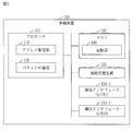
- FIG. The block diagram of the relay device 100 in Embodiment 1.
- FIG. The block diagram of the address management unit 110 in Embodiment 1.
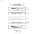
- FIG. The flowchart of the address management process in Embodiment 1.
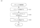
- FIG. The flowchart of the packet relay processing in Embodiment 1.
- FIG. The block diagram of the network system 200 in Embodiment 2.
- FIG. The block diagram of the address in Embodiment 2.
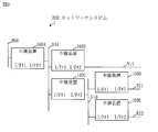
- the flowchart of the next hop address generation processing (S220) in Embodiment 2. The block diagram of the relay device 100 in Embodiment 3.
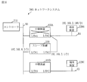
- the block diagram of the network system 200 (normal state) in Embodiment 3.
- FIG. The block diagram of the network system 200 (at the time of failure) in Embodiment 3.
- Embodiment 1 The network system 200 will be described with reference to FIGS. 1 to 8.
- the network system 200 is a communication system in a network composed of a plurality of subnets (N0 to N3).
- the network system 200 includes a controller 210, a plurality of relay devices (100A to 100C), and a plurality of terminal devices (220A to 220C).
- the relay device (100A to 100C) is not specified, each is referred to as a relay device 100.
- the terminal devices (220A to 220C) are not specified, each is referred to as a terminal device 220.
- the controller 210 is a computer that controls the network system 200, and is connected to the subnet N0.
- the relay device 100 is a communication device that is connected to the upper network and the lower network and relays packets. Specifically, the relay device 100 is a router.
- the relay device 100 includes I / F # 1 and I / F # 2.
- I / F # 1 is connected to the upper network and I / F # 2 is connected to the lower network.
- I / F is an abbreviation for interface.
- the relay device 100A is connected to subnet N0 and subnet N1.
- the upper network in the relay device 100A is subnet N0
- the lower network in the relay device 100A is subnet N1.
- the relay device 100B is connected to subnet N0 and subnet N2.
- the upper network in the relay device 100B is subnet N0
- the lower network in the relay device 100B is subnet N2.
- the relay device 100C is connected to subnet N0 and subnet N3.
- the upper network in the relay device 100C is subnet N0, and the lower network in the relay device 100C is subnet N3.
- the terminal device 220 is a computer connected to the lower network of the relay device 100.
- the terminal device 220A is connected to the subnet N1.
- the terminal device 220B is connected to the subnet N2.
- the terminal device 220C is connected to the subnet N3.
- the configuration of the relay device 100 will be described with reference to FIG.
- the relay device 100 is a computer including hardware such as a processor 101, a memory 102, an auxiliary storage device 103, and a plurality of communication interfaces (104-1, 104-2). These hardware are connected to each other via signal lines.
- the communication interface (104-1, 104-2) is not specified, each is referred to as a communication interface 104.
- the processor 101 is an IC that performs arithmetic processing and controls other hardware.
- the processor 101 is a CPU, DSP or GPU.
- IC is an abbreviation for Integrated Circuit.
- CPU is an abbreviation for Central Processing Unit.
- DSP is an abbreviation for Digital Signal Processor.
- GPU is an abbreviation for Graphics Processing Unit.
- the memory 102 is a volatile storage device.
- the memory 102 is also called a main storage device or a main memory.
- the memory 102 is a RAM.
- the data stored in the memory 102 is stored in the auxiliary storage device 103 as needed.
- RAM is an abbreviation for Random Access Memory.
- the auxiliary storage device 103 is a non-volatile storage device.
- the auxiliary storage device 103 is a ROM, HDD, or flash memory.
- the data stored in the auxiliary storage device 103 is loaded into the memory 102 as needed.
- ROM is an abbreviation for Read Only Memory.
- HDD is an abbreviation for Hard Disk Drive.
- the communication interface 104 is an interface (port) for communication.
- the communication interface 104-1 is referred to as I / F # 1
- the communication interface 104-2 is referred to as I / F # 2.
- the relay device 100 includes elements such as an address management unit 110 and a packet relay unit 120. These elements are realized in software.
- the auxiliary storage device 103 stores a relay program for operating the computer as the address management unit 110 and the packet relay unit 120.
- the relay program is loaded into the memory 102 and executed by the processor 101.
- the OS is further stored in the auxiliary storage device 103. At least a portion of the OS is loaded into memory 102 and executed by processor 101.
- the processor 101 executes a relay program while executing the OS.
- OS is an abbreviation for Operating System.
- the input / output data of the relay program is stored in the storage unit 190.
- the memory 102 functions as a storage unit 190.
- a storage device such as an auxiliary storage device 103, a register in the processor 101, and a cache memory in the processor 101 may function as a storage unit 190 instead of the memory 102 or together with the memory 102.
- the relay device 100 may include a plurality of processors that replace the processor 101.
- the plurality of processors share the role of the processor 101.
- the relay program can be computer-readablely recorded (stored) in a non-volatile recording medium such as a flash memory.
- the configuration of the address management unit 110 will be described with reference to FIG.
- the address management unit 110 includes elements such as an address information acquisition unit 111, an address setting unit 112, a subnet address generation unit 113, and an address information providing unit 114. The functions of these elements will be described later.
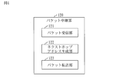
- the configuration of the packet relay unit 120 will be described with reference to FIG.
- the packet relay unit 120 includes elements such as a packet reception unit 121, a next hop address generation unit 122, and a packet transfer unit 123. The functions of these elements will be described later.
- the procedure for operating the relay device 100 corresponds to the relay method. Further, the operation procedure of the relay device 100 corresponds to the processing procedure by the relay program.
- address means a communication address.
- IP is an abbreviation for Internet Protocol.
- the address management process will be described with reference to FIG.
- the address management process is a process executed by the address management unit 110 (see FIG. 3).
- step S111 the address information acquisition unit 111 acquires the address information for the relay device 100. Then, the address information acquisition unit 111 stores the address information for the relay device 100 in the storage unit 190.
- the address information for the relay device 100 indicates the address of the relay device 100 in the upper network. This address is referred to as an "upper address".
- the upper address indicates the network address of the upper network, the host address of the relay device 100 in the upper network, and the network mask length.
- the network address is also called the network part, and the host address is also called the host part.
- the network mask length is the length of the network mask and is also called the subnet mask length.
- the network mask is also called the subnet mask.
- step S111 A specific example of step S111 will be described with reference to FIG.
- the controller 210 distributes the address information for the relay device 100A to the relay device 100A.
- DHCP in the IP protocol is well known.
- DHCP is an abbreviation for Dynamic Host Configuration Protocol.
- the address information acquisition unit 111 receives the address information distributed from the controller 210 by I / F # 1.
- the address information for the relay device 100A indicates "192.168.0.2 / 24".
- step S112 the address setting unit 112 extracts the upper address from the address information for the relay device 100, and sets the extracted upper address in I / F # 1.
- step S112 extracts the upper address "192.168.0.2 / 24" from the address information for the relay device 100A, and sets the extracted upper address in I / F # 1.
- step S113 the subnet address generation unit 113 generates a subnet address that is a network address of the lower network based on the address information for the relay device 100. Specifically, the subnet address generation unit 113 replaces the lower-order bit portion of the bit string representing the network address shown in the address information with the bit string representing the host address shown in the address information. The network address obtained by this becomes the subnet address.
- step S113 A specific example of step S113 will be described with reference to FIG.
- the address information for the relay device 100A indicates "192.168.0.2 / 24".
- “192.168.0” is the network address
- “2” is the host address
- “24” is the network mask length.
- the subnet address "192.168.2.0 / 24" is generated.
- the mask length M may be preset in the storage unit 190 or may be acquired as a part of the address information.
- step S114 the address setting unit 112 generates the address of the relay device 100 in the lower network based on the generated subnet address. This address is referred to as a "lower address”.
- the address setting unit 112 sets the generated lower address to I / F # 2.
- the address setting unit 112 selects a host address to be assigned to the relay device 100 from the host address range based on the generated subnet address.
- the address indicating the generated subnet address and the selected host address is the lower address.
- step S114 A specific example of step S114 will be described with reference to FIG.
- the address setting unit 112 selected the host address "1" from the host address range "1 to 255" based on the subnet address "192.168.2.0 / 24". In this case, the lower address of the relay device 100A is "192.168.2.1".
- the address setting unit 112 sets the lower address to I / F # 2.
- step S115 the address information providing unit 114 generates the address information for the terminal device 220 based on the generated subnet address. Then, the address information providing unit 114 provides the address information for the terminal device 220 to the terminal device 220.
- the address information for the terminal device 220 indicates the address of the terminal device 220 in the lower network and the address of the default gateway in the lower network. Specifically, the address information providing unit 114 selects a host address to be assigned to the terminal device 220 from the host address range based on the generated subnet address. The address indicating the generated subnet address and the selected host address is the address of the terminal device 220 in the lower network.
- the default gateway in the lower network is the relay device 100. That is, the address of the default gateway in the lower network is the address of the relay device 100 in the lower network.
- step S115 A specific example of step S115 will be described with reference to FIG.
- the address information providing unit 114 selected the host address "100" from the host host address range "1 to 255" based on the subnet address "192.168.2.0 / 24".
- the address of the terminal device 220A in the subnet N1 is "192.168.2.100/24".
- the lower address of the relay device 100A is "192.168.2.1”.
- the address information providing unit 114 distributes the address information for the terminal device 220 to the terminal device 220A in response to the address distribution request from the terminal device 220A.
- DHCP in the IP protocol is well known.
- the address information for the terminal device 220 indicates "192.168.2.100/24" and "192.168.2.1".
- the terminal device 220A sets "192.168.2.100/24" as the address of the terminal device 220A, and sets "192.168.2.1" as the address of the default gateway.
- the packet relay process will be described with reference to FIG. 7.
- the packet relay process is a process executed by the packet relay unit 120.
- step S121 the packet receiving unit 121 receives a packet from the terminal device 220 connected to the lower network to the destination device.
- This destination device is a terminal device connected to a subnet different from the lower network.
- the subnet to which this destination device connects is called a destination subnet.
- the next hop address generation unit 122 generates the next hop address as follows.
- the next hop address is the address of the next hop.
- the next hop is a device identified by the next hop address and is a packet forwarding destination.
- the next hop is connected to the upper network and the destination subnet.
- next hop address generation unit 122 extracts the address of the destination device from the received packet. Specifically, the next hop address generation unit 122 extracts the destination address from the received packet.
- next hop address generation unit 122 extracts the network address of the destination subnet from the address of the destination device. Specifically, the next hop address generation unit 122 extracts the network address from the destination address by using the network mask length shown in the address information for the relay device 100. The extracted network address is the network address of the destination subnet.
- next hop address generator 122 extracts the lower bit portion from the bit string representing the network address of the destination subnet.
- next hop address generation unit 122 generates an address by combining the network address of the upper network with the extracted lower bit portion as the host address.
- the generated address is the next hop address.
- step S123 the packet transfer unit 123 transfers the received packet to the next hop.
- the terminal device 220A transmits the packet P1 destined for the terminal device 220C.
- the subnet N1 network address: 192.168.2
- the subnet N3 network address: 192.168.4
- the terminal device 220A transmits the packet P1 with the default gateway (address: 192.168.2.1) as the next hop.
- the destination address of packet P1, that is, the address of the terminal device 220C is "192.1684.4.100".
- the packet receiving unit 121 receives the packet P1.
- the next hop address generation unit 122 generates the next hop address "192.168.0.4" based on the destination address of the packet P1.
- the packet transfer unit 123 transfers the packet P1 to the relay device 100C identified by the next hop address.
- the relay device 100C receives the packet P1.
- the network address "192.168.4" in the destination address of the packet P1 is the network address of the subnet N3.
- the relay device 100C is connected to the subnet N3. Therefore, the relay device 100C transfers the packet P1 to the terminal device 220C on the subnet N3. Then, the terminal device 220C receives the packet P1.
- the network system 200 can be applied to an air-conditioned network.
- the outdoor unit functions as the relay device 100.
- An address distribution server may be provided in the network system 200. In that case, the address distribution server distributes the address information instead of the controller 210.
- Each relay device 100 can determine the address for the lower network interface (I / F # 2) and the address for the terminal device 220 only by obtaining the address for the upper network interface (I / F # 1). .. Therefore, it is not necessary to individually set the addresses for each relay device 100 and each terminal device 220. Therefore, the setting of each relay device 100 can be simplified.
- the relay device 100 Since the relay device 100 does not need to have a routing table, it is not necessary to perform a process of searching the routing table. However, the relay device 100 can generate the next hop address and forward the packet. That is, the relay device 100 does not require a memory for the routing table, and does not impose a processing load for searching the routing table. Further, since the relay device 100 does not need to exchange route information between the devices in order to construct the routing table, the relay device 100 is not burdened with the processing for exchanging the route information. Therefore, it is possible to reduce the amount of resources required for the relay device 100.
- Embodiment 2 A mode in which the network system 200 is composed of subnets having a plurality of layers will be described mainly different from the first embodiment with reference to FIGS. 9 to 13.
- the configuration of the network system 200 will be described with reference to FIG.
- the network system 200 is layered in a tree shape and is composed of subnets having a plurality of layers. Each relay device 100 is arranged between subnets of two consecutive layers.
- the relay device 100A is arranged between the 0th layer subnet N00 and the 1st layer subnet N01.
- the 0th layer subnet N00 is the upper network
- the 1st layer subnet N01 is the lower network.
- the relay device 100B is arranged between the first layer subnet N01 and the second layer subnet N11.
- the first layer subnet N01 is the upper network
- the second layer subnet N11 is the lower network.
- the relay device 100C is arranged between the first layer subnet N01 and the second layer subnet N10.
- the first layer subnet N01 is the upper network
- the second layer subnet N10 is the lower network.
- the relay device 100D is arranged between the subnet N10 of the second layer and the subnet N21 of the third layer.
- the second layer subnet N10 is the upper network
- the third layer subnet N21 is the lower network.
- the relay device 100E is arranged between the subnet N10 of the second layer and the subnet N22 of the third layer.
- the second layer subnet N10 is the upper network
- the third layer subnet N22 is the lower network.
- each relay device 100 It is the same as the configuration in the first embodiment (see FIGS. 2 to 4).
- the address has a network unit and a host unit.
- the network unit has a network mask length L and indicates the network address of the subnet of each layer.
- the host part indicates the host address of the device belonging to the subnet of each layer.
- the network unit has a common unit and an individual unit.
- the common part indicates a subnet address common to one or more subnets belonging to the same hierarchy.
- the individual part indicates a different subnet address for each subnet belonging to the same hierarchy.
- the mask length corresponding to the entire subnet address (common part + individual part) in the Nth layer is referred to as "individual mask length L_N”.
- the mask length corresponding to the common part of the subnet addresses in the Nth layer is referred to as "common mask length C_N”.
- the individual mask length L_N of the Nth layer is equal to the common mask length C_ (N + 1) of the (N + 1) layer.
- the common mask length C_N of the Nth layer is equal to the individual mask length L_ (N-1) of the (N-1) layer.
- the relay device 100 arranged between the Nth layer and the (N + 1) layer is referred to as the Nth layer relay device 100.
- the storage unit 190 of the relay device 100 of the Nth layer stores mask lengths such as network mask length L, individual mask length L_N, common mask length C_N, and common mask length C_ (N + 1).
- the network mask length L corresponds to the network address length of the upper network, and is stored in the storage unit 190 as a part of the address information.
- Each mask length other than the network mask length L may be stored in the storage unit 190 in advance, or may be stored in the storage unit 190 as a part of the address information.
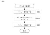
- Step S210 the packet receiving unit 121 receives the packet.
- Step S210 is the same as step S121 in the first embodiment (see FIG. 7).
- step S220 the next hop address generation unit 122 generates the next hop address.
- next hop address generation process (S220) in the N-layer relay device 100 will be described with reference to FIGS. 12 and 13.
- the next hop address generation unit 122 determines whether the destination network address matches the lower subnet address as follows.
- next hop address generation unit 122 extracts the destination address from the received packet.
- the next hop address generation unit 122 extracts the destination network address from the extracted destination addresses.
- the destination network address is a subnet mask for the upper network, that is, a network address based on the subnet mask having a network mask length L.
- the next hop address generation unit 122 compares the extracted destination network address with the lower subnet address.
- the lower subnet address is the network address of the lower network.
- step S222 If the destination network address matches the lower subnet address, the process proceeds to step S222. If the destination network address does not match the lower subnet address, the process proceeds to step S223.
- step S222 the next hop address generation unit 122 determines the destination address of the received packet as the next hop address. After step S222, the process ends.
- step S223 the next hop address generation unit 122 determines whether the destination network address matches the upper subnet address.
- the destination network address is obtained in step S221.
- the upper subnet address is the network address of the upper network.
- step S224 If the destination network address matches the higher subnet address, the process proceeds to step S224. If the destination network address does not match the higher subnet address, the process proceeds to step S225.
- step S224 the next hop address generation unit 122 determines the destination address of the received packet as the next hop address. After step S224, the process ends.
- step S225 the next hop address generation unit 122 determines whether the Nth layer network address matches the lower layer network address as follows.
- the next hop address generation unit 122 extracts the N-layer network address from the destination address of the received packet.
- the N-layer network address is a network address based on the N-layer subnet mask.
- the Nth layer subnet mask is a subnet mask having an individual mask length L_N.
- the next hop address generation unit 122 extracts the network address based on the Nth layer subnet mask from the subnet address of the lower network.
- the extracted network address is called a lower layer network address.
- the next hop address generation unit 122 compares the Nth layer network address with the lower layer network address.
- step S226 If the Nth layer network address matches the lower layer network address, the process proceeds to step S226. If the Nth layer network address does not match the lower layer network address, the process proceeds to step S227.
- the next hop address generation unit 122 generates the next hop address as follows. First, the next hop address generation unit 122 extracts the (N + 1) layer network address from the destination address of the received packet.
- the first (N + 1) layer network address is a network address based on the (N + 1) layer subnet mask.
- the first (N + 1) layer subnet mask is a subnet mask having an individual mask length L_ (N + 1).
- the next hop address generation unit 122 extracts a lower bit string from the bit string representing the extracted (N + 1) layer network address.
- the lower bit string has the number of bits obtained by "L_ (N + 1) -L_N".
- the host address represented by the extracted lower bit string is referred to as a host address H_ (N + 1).
- the next hop address generation unit 122 generates an address by combining the host address H_ (N + 1) with the lower subnet address.
- the generated address will be the next hop address.
- step S227 the next hop address generation unit 122 determines whether the (N-1) layer network address matches the lower layer network address as follows.
- the next hop address generation unit 122 extracts the (N-1) layer network address from the destination address of the received packet.
- the (N-1) layer network address is a network address based on the (N-1) layer subnet mask.
- the first (N-1) layer subnet mask is a subnet mask having an individual mask length L_ (N-1), that is, a common mask length C_N.
- the next hop address generation unit 122 extracts a network address based on the (N-1) layer subnet mask from the network address of the upper network.
- the extracted network address is called an upper layer network address.
- the next hop address generation unit 122 compares the (N-1) layer network address with the upper layer network address.
- step S228 If the first (N-1) layer network address matches the upper layer network address, the process proceeds to step S228. If the first (N-1) layer network address does not match the upper layer network address, the next hop address is not generated and the process ends.
- step S228, the next hop address generation unit 122 generates the next hop address as follows. First, the next hop address generation unit 122 extracts a lower bit string from the bit string representing the Nth layer network address. The Nth layer network address is extracted in step S225. The lower bit string has the number of bits obtained by "L_N-C_N". The host address represented by the extracted lower bit string is referred to as a host address H_N. Then, the next hop address generation unit 122 generates an address by combining the host address H_N with the upper subnet address. The generated address will be the next hop address. After step S228, the process ends.
- step S230 the packet transfer unit 123 transfers the received packet to the next hop.
- the packet transfer unit 123 operates as follows.
- the packet forwarding unit 123 forwards the packet to the next hop of the lower network.
- the packet transfer unit 123 discards the packet without forwarding it.
- the packet forwarding unit 123 forwards the packet to the next hop of the upper network.
- the packet forwarding unit 123 discards the packet without forwarding it.
- the next hop address is generated in step S226 (see FIG.
- the packet forwarding unit 123 forwards the packet to the next hop of the lower network. However, when the communication interface in which the packet is received is I / F # 2, the packet transfer unit 123 discards the packet without forwarding it.
- the packet transfer unit 123 transfers the packet to the next hop of the upper network. However, when the communication interface in which the packet is received is I / F # 1, the packet forwarding unit 123 discards the packet without forwarding it.
- the packet transfer unit 123 When the next hop address is neither determined nor generated, the packet transfer unit 123 operates as follows. When the relay device 100 is not the relay device of the uppermost layer and the communication interface in which the packet is received is I / F # 2, the packet transfer unit 123 transfers the packet to the default gateway of the upper network. When the relay device 100 is the uppermost relay device, the packet transfer unit 123 discards the packet without forwarding it. When the communication interface in which the packet is received is I / F # 1, the packet forwarding unit 123 discards the packet without forwarding it.
- the network can be layered in a plurality of stages. Therefore, the network system 200 can be configured flexibly in response to the system to which the network system 200 is applied.
- the relay device 100 Since the relay device 100 does not need to have a routing table, it is not necessary to perform a process of searching the routing table. However, the relay device 100 can generate the next hop address and forward the packet. That is, the relay device 100 does not require a memory for the routing table, and does not impose a processing load for searching the routing table. Further, since the relay device 100 does not need to exchange route information between the devices in order to construct the routing table, the relay device 100 is not burdened with the processing for exchanging the route information. Therefore, it is possible to reduce the amount of resources required for the relay device 100.
- Embodiment 3 A form in which the network system 200 is configured to be redundant will be described mainly different from the first embodiment with reference to FIGS. 14 to 16.
- the configuration of the relay device 100 will be described with reference to FIG.
- the relay device 100 further includes a redundancy unit 130.
- the relay program further causes the computer to function as a redundancy unit 130.
- the communication and processing related to redundancy described below are executed by the redundancy unit 130.
- the configuration of the network system 200 will be described with reference to FIG.
- the network system 200 further includes a slave device 230.
- the configuration of subnet N2 (see FIG. 1) is not shown.
- the slave device 230 is a relay device 100 that is an alternative to the relay device 100A.
- the slave device 230 is connected to the upper network (N0) and the lower network (N1) of the relay device 100A.
- the slave device 230 takes over the address of the relay device 100A and operates in place of the relay device 100A.
- black circles mean that I / F # 1 of the slave device 230A is in an invalid state while the relay device 100A is operating normally.
- the configuration of the slave device 230 is the same as the configuration of each relay device 100 (see FIG. 14).
- the operation of the slave device 230 when the relay device 100A is operating normally will be described with reference to FIG.
- the slave device 230 communicates with the relay device 100A according to the redundancy protocol of the default gateway.
- a specific redundancy protocol is the Virtual Router Redundancy Protocol (VRRP).
- VRRP is standardized by RFC2338.
- the relay device 100A serves as a VRRP master and periodically transmits VRRP packets.
- the slave device 230 receives the VRRP packet.
- the slave device 230 can acquire the address (192.168.2.1 / 24) of the relay device 100A in the lower network (N1).
- the relay device 100A While the relay device 100A is operating normally, the relay process between the subnet N1 and another subnet is performed by the relay device 100A. Further, in order to prevent a loop of relay processing, while the slave device 230 is performing the VRRP backup operation on the lower network (N1), the slave device 230 invalidates I / F # 1 for the upper network (N0). ..
- the slave device 230 becomes a VRRP master by operating according to VRRP in the lower network (N1). Then, the slave device 230 takes over the address (192.168.2.1 / 24) of the relay device 100A in the lower network (N1). At this time, the slave device 230 sets the takeover address to I / F # 2. This address is the default gateway address of the lower network (N1). After that, the slave device 230 assigns the address of the relay device 100A in the upper network (192.168.0.2 / 24) based on the address of the relay device 100A in the lower network (192.168.2.1/24). take over. At this time, the slave device 230 sets the takeover address to I / F # 1. Then, the slave device 230 activates I / F # 1.
- the address of the relay device 100A in the upper network is calculated as follows. First, the slave device 230 extracts the network address of the lower network from the address (192.168.2.1 / 24) of the relay device 100A in the lower network. The extracted network address is "192.168.2". Next, the slave device 230 extracts the lower bit portion from the network address (192.168.2) of the lower network. Specifically, the slave device 230 extracts the lower M bits. The extracted lower M bits are used as the host address. The host address is "2". Then, the slave device 230 combines the network address (192.168.0) of the upper network and the host address (2). The obtained address (192.168.0.2) is the address of the relay device 100A in the upper network.
- the packet is transferred to the slave device 230 by the packet relay process (see FIG. 7) in the relay device 100B. As a result, the packet reaches the terminal device 220A via the slave device 230.
- the network system 200 may be composed of subnets having a plurality of layers, and slave devices 230 may be provided in each subnet.
- Embodiment 3 it is possible to support a redundant network configuration while taking advantage of the feature that the routing table is not managed. Then, it becomes possible to construct a highly reliable network system 200.
- the relay device 100 Since the relay device 100 does not need to have a routing table, it is not necessary to perform a process of searching the routing table. However, the relay device 100 can generate the next hop address and forward the packet. That is, the relay device 100 does not require a memory for the routing table, and does not impose a processing load for searching the routing table. Further, since the relay device 100 does not need to exchange route information between the devices in order to construct the routing table, the relay device 100 is not burdened with the processing for exchanging the route information. Therefore, it is possible to reduce the amount of resources required for the relay device 100.
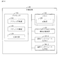
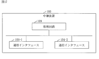
- the relay device 100 includes a processing circuit 109.
- the processing circuit 109 is hardware that realizes the address management unit 110, the packet relay unit 120, and the redundancy unit 130.
- the processing circuit 109 may be dedicated hardware or a processor 101 that executes a program stored in the memory 102.
- the processing circuit 109 is dedicated hardware, the processing circuit 109 is, for example, a single circuit, a composite circuit, a programmed processor, a parallel programmed processor, an ASIC, an FPGA, or a combination thereof.
- ASIC is an abbreviation for Application Specific Integrated Circuit.
- FPGA is an abbreviation for Field Programmable Gate Array.
- the relay device 100 may include a plurality of processing circuits that replace the processing circuit 109.
- the plurality of processing circuits share the functions of the processing circuit 109.
- relay device 100 some functions may be realized by dedicated hardware, and the remaining functions may be realized by software or firmware.
- each function of the relay device 100 can be realized by hardware, software, firmware, or a combination thereof.
- the embodiments are examples of preferred embodiments and are not intended to limit the technical scope of the invention.
- the embodiment may be partially implemented or may be implemented in combination with other embodiments.
- the procedure described using the flowchart or the like may be appropriately changed.
- the "part” which is an element of the relay device 100 may be read as “processing” or "process”.
- 100 relay device 101 processor, 102 memory, 103 auxiliary storage device, 104 communication interface, 109 processing circuit, 110 address management unit, 111 address information acquisition unit, 112 address setting unit, 113 subnet address generation unit, 114 address information provision unit.
Landscapes
- Engineering & Computer Science (AREA)
- Computer Networks & Wireless Communication (AREA)
- Signal Processing (AREA)
- Data Exchanges In Wide-Area Networks (AREA)
- Small-Scale Networks (AREA)
Abstract
L'invention concerne un dispositif de relais (100A) acquérant des informations d'adresse indiquant l'adresse réseau d'un réseau supérieur (N0) et l'adresse d'hôte du dispositif de relais. Le dispositif de relais génère une adresse de sous-réseau à utiliser en tant qu'adresse de réseau d'un réseau inférieur (N1) par réécriture de la partie de bit inférieure de l'adresse de réseau indiquée par les informations d'adresse avec l'adresse d'hôte indiquée par les informations d'adresse. Le dispositif de relais sélectionne une adresse d'hôte devant être attribuée à un dispositif terminal (220A) depuis l'intérieur d'une plage d'adresses d'hôtes sur la base de l'adresse de sous-réseau et fournit au dispositif terminal des informations d'adresse indiquant l'adresse de sous-réseau et l'adresse d'hôte sélectionnée.
Priority Applications (5)
| Application Number | Priority Date | Filing Date | Title |
|---|---|---|---|
| CN201980097941.2A CN114073061A (zh) | 2019-07-05 | 2019-07-05 | 中继装置和网络系统 |
| EP19937292.1A EP3979573A4 (fr) | 2019-07-05 | 2019-07-05 | Dispositif de relais et système de réseau |
| PCT/JP2019/026840 WO2021005651A1 (fr) | 2019-07-05 | 2019-07-05 | Dispositif de relais et système de réseau |
| JP2021530350A JP7038915B2 (ja) | 2019-07-05 | 2019-07-05 | 中継装置およびネットワークシステム |
| US17/523,526 US20220070142A1 (en) | 2019-07-05 | 2021-11-10 | Transferring device and network system |
Applications Claiming Priority (1)
| Application Number | Priority Date | Filing Date | Title |
|---|---|---|---|
| PCT/JP2019/026840 WO2021005651A1 (fr) | 2019-07-05 | 2019-07-05 | Dispositif de relais et système de réseau |
Related Child Applications (1)
| Application Number | Title | Priority Date | Filing Date |
|---|---|---|---|
| US17/523,526 Continuation US20220070142A1 (en) | 2019-07-05 | 2021-11-10 | Transferring device and network system |
Publications (1)
| Publication Number | Publication Date |
|---|---|
| WO2021005651A1 true WO2021005651A1 (fr) | 2021-01-14 |
Family
ID=74113937
Family Applications (1)
| Application Number | Title | Priority Date | Filing Date |
|---|---|---|---|
| PCT/JP2019/026840 Ceased WO2021005651A1 (fr) | 2019-07-05 | 2019-07-05 | Dispositif de relais et système de réseau |
Country Status (5)
| Country | Link |
|---|---|
| US (1) | US20220070142A1 (fr) |
| EP (1) | EP3979573A4 (fr) |
| JP (1) | JP7038915B2 (fr) |
| CN (1) | CN114073061A (fr) |
| WO (1) | WO2021005651A1 (fr) |
Cited By (2)
| Publication number | Priority date | Publication date | Assignee | Title |
|---|---|---|---|---|
| WO2023139740A1 (fr) * | 2022-01-21 | 2023-07-27 | 三菱電機株式会社 | Système de climatisation |
| JP7553829B2 (ja) | 2022-03-31 | 2024-09-19 | ダイキン工業株式会社 | 空調関連機器及び空調システム |
Citations (2)
| Publication number | Priority date | Publication date | Assignee | Title |
|---|---|---|---|---|
| JP2013126209A (ja) * | 2011-12-16 | 2013-06-24 | Panasonic Corp | 無線ネットワークシステム、無線通信装置、及び、無線通信装置のプログラム |
| JP2014120918A (ja) * | 2012-12-17 | 2014-06-30 | Mitsubishi Electric Corp | スマートメータシステム、管理ルータおよびメータ |
Family Cites Families (8)
| Publication number | Priority date | Publication date | Assignee | Title |
|---|---|---|---|---|
| DE102005004151A1 (de) * | 2005-01-28 | 2006-08-10 | Siemens Ag | Verfahren und Vorrichtung zur Zuordnung von Paketadressen einer Mehrzahl von Einrichtung |
| US8550368B2 (en) * | 2005-02-23 | 2013-10-08 | Emerson Electric Co. | Interactive control system for an HVAC system |
| KR100653527B1 (ko) * | 2005-05-30 | 2006-12-05 | 주식회사 팬택앤큐리텔 | 인터넷 프로토콜 주소 운용 방법 |
| US8027271B2 (en) * | 2006-05-30 | 2011-09-27 | Panasonic Corporation | Communicating apparatus and controlling method of thereof |
| US10291578B2 (en) * | 2014-10-27 | 2019-05-14 | Hewlett Packard Enierprise Development LP | Method to distribute a centralized service |
| WO2016121043A1 (fr) * | 2015-01-29 | 2016-08-04 | 三菱電機株式会社 | Système de réseau, dispositif de gestion d'adresses et procédé de gestion d'adresses |
| US10230629B2 (en) * | 2015-08-11 | 2019-03-12 | Nicira, Inc. | Static route configuration for logical router |
| JP6579025B2 (ja) * | 2016-04-15 | 2019-09-25 | 三菱電機株式会社 | パケット中継装置、パケット中継制御装置、パケット中継システムおよびパケット中継方法 |
-
2019
- 2019-07-05 WO PCT/JP2019/026840 patent/WO2021005651A1/fr not_active Ceased
- 2019-07-05 EP EP19937292.1A patent/EP3979573A4/fr not_active Withdrawn
- 2019-07-05 CN CN201980097941.2A patent/CN114073061A/zh active Pending
- 2019-07-05 JP JP2021530350A patent/JP7038915B2/ja active Active
-
2021
- 2021-11-10 US US17/523,526 patent/US20220070142A1/en not_active Abandoned
Patent Citations (2)
| Publication number | Priority date | Publication date | Assignee | Title |
|---|---|---|---|---|
| JP2013126209A (ja) * | 2011-12-16 | 2013-06-24 | Panasonic Corp | 無線ネットワークシステム、無線通信装置、及び、無線通信装置のプログラム |
| JP2014120918A (ja) * | 2012-12-17 | 2014-06-30 | Mitsubishi Electric Corp | スマートメータシステム、管理ルータおよびメータ |
Non-Patent Citations (2)
| Title |
|---|
| HIROSHI MIYATA: "An introduction to network technology & design for infrastructure/network engineers", SB CREATIVE CORP, December 2013 (2013-12-01) |
| See also references of EP3979573A4 |
Cited By (4)
| Publication number | Priority date | Publication date | Assignee | Title |
|---|---|---|---|---|
| WO2023139740A1 (fr) * | 2022-01-21 | 2023-07-27 | 三菱電機株式会社 | Système de climatisation |
| JPWO2023139740A1 (fr) * | 2022-01-21 | 2023-07-27 | ||
| JP7621521B2 (ja) | 2022-01-21 | 2025-01-24 | 三菱電機株式会社 | 空調システム |
| JP7553829B2 (ja) | 2022-03-31 | 2024-09-19 | ダイキン工業株式会社 | 空調関連機器及び空調システム |
Also Published As
| Publication number | Publication date |
|---|---|
| EP3979573A1 (fr) | 2022-04-06 |
| US20220070142A1 (en) | 2022-03-03 |
| EP3979573A4 (fr) | 2022-06-08 |
| JPWO2021005651A1 (ja) | 2021-10-21 |
| JP7038915B2 (ja) | 2022-03-18 |
| CN114073061A (zh) | 2022-02-18 |
Similar Documents
| Publication | Publication Date | Title |
|---|---|---|
| US11695730B2 (en) | Providing services for logical networks | |
| US9104625B2 (en) | Disaster recovery internet protocol address failover | |
| TWI543566B (zh) | 基於軟體定義網路的資料中心網路系統及其封包傳送方法、位址解析方法與路由控制器 | |
| JP4862743B2 (ja) | ノード、通信方法およびノード用プログラム | |
| CN113572831B (zh) | Kubernetes集群间的通信方法、计算机设备及介质 | |
| JP6079426B2 (ja) | 情報処理システム、方法、装置及びプログラム | |
| CN108494675A (zh) | 实现虚拟路由冗余协议备份组的方法、装置和路由设备 | |
| US11671345B2 (en) | Self-expansion of a layer 3 network fabric | |
| CN113973022A (zh) | 通信方法、cp设备及nat设备 | |
| US8908702B2 (en) | Information processing apparatus, communication apparatus, information processing method, and relay processing method | |
| JP7038915B2 (ja) | 中継装置およびネットワークシステム | |
| US20080056122A1 (en) | Method and system of transmit load balancing across multiple physical ports | |
| US9413654B2 (en) | System, relay device, method, and medium | |
| WO2021252004A1 (fr) | Services de réseau modulaires par le biais de boîtiers intermédiaires élastiques répartis | |
| CN114024971B (zh) | 业务数据处理方法、Kubernetes集群及介质 | |
| CN112612201B (zh) | 自动化系统、创建自动化系统的方法和计算机可读介质 | |
| US11023268B2 (en) | Computer system and computer | |
| CN119182828A (zh) | 外网访问方法、装置、计算机设备、可读存储介质和产品 | |
| CN114138406B (zh) | 一种应用容器快速部署平台 | |
| US20130262701A1 (en) | Method and a network element for content based addressing in a data transfer network | |
| JP3783664B2 (ja) | ルータ装置およびプログラム | |
| CN113852473A (zh) | 一种集群部署方法、装置及存储介质 | |
| CN115987787B (zh) | 一种远端设备自动配置的方法和装置及设备 | |
| JP6203447B2 (ja) | 転送装置 | |
| US12301420B2 (en) | Unicast to multicast service reflection in SD-WAN fabric |
Legal Events
| Date | Code | Title | Description |
|---|---|---|---|
| 121 | Ep: the epo has been informed by wipo that ep was designated in this application |
Ref document number: 19937292 Country of ref document: EP Kind code of ref document: A1 |
|
| ENP | Entry into the national phase |
Ref document number: 2021530350 Country of ref document: JP Kind code of ref document: A |
|
| ENP | Entry into the national phase |
Ref document number: 2019937292 Country of ref document: EP Effective date: 20211229 |
|
| NENP | Non-entry into the national phase |
Ref country code: DE |