WO2021005774A1 - Rotor, moteur et procédé de production de rotor - Google Patents
Rotor, moteur et procédé de production de rotor Download PDFInfo
- Publication number
- WO2021005774A1 WO2021005774A1 PCT/JP2019/027478 JP2019027478W WO2021005774A1 WO 2021005774 A1 WO2021005774 A1 WO 2021005774A1 JP 2019027478 W JP2019027478 W JP 2019027478W WO 2021005774 A1 WO2021005774 A1 WO 2021005774A1
- Authority
- WO
- WIPO (PCT)
- Prior art keywords
- rotor
- adhesive layer
- reinforced plastic
- fiber
- iron core
- Prior art date
- Legal status (The legal status is an assumption and is not a legal conclusion. Google has not performed a legal analysis and makes no representation as to the accuracy of the status listed.)
- Ceased
Links
Images


Classifications
-
- H—ELECTRICITY
- H02—GENERATION; CONVERSION OR DISTRIBUTION OF ELECTRIC POWER
- H02K—DYNAMO-ELECTRIC MACHINES
- H02K1/00—Details of the magnetic circuit
- H02K1/06—Details of the magnetic circuit characterised by the shape, form or construction
- H02K1/22—Rotating parts of the magnetic circuit
- H02K1/27—Rotor cores with permanent magnets
- H02K1/2706—Inner rotors
- H02K1/272—Inner rotors the magnetisation axis of the magnets being perpendicular to the rotor axis
- H02K1/274—Inner rotors the magnetisation axis of the magnets being perpendicular to the rotor axis the rotor consisting of two or more circumferentially positioned magnets
- H02K1/2753—Inner rotors the magnetisation axis of the magnets being perpendicular to the rotor axis the rotor consisting of two or more circumferentially positioned magnets the rotor consisting of magnets or groups of magnets arranged with alternating polarity
- H02K1/278—Surface mounted magnets; Inset magnets
-
- H—ELECTRICITY
- H02—GENERATION; CONVERSION OR DISTRIBUTION OF ELECTRIC POWER
- H02K—DYNAMO-ELECTRIC MACHINES
- H02K15/00—Processes or apparatus specially adapted for manufacturing, assembling, maintaining or repairing of dynamo-electric machines
- H02K15/02—Processes or apparatus specially adapted for manufacturing, assembling, maintaining or repairing of dynamo-electric machines of stator or rotor bodies
- H02K15/03—Processes or apparatus specially adapted for manufacturing, assembling, maintaining or repairing of dynamo-electric machines of stator or rotor bodies having permanent magnets
Definitions
- the present invention relates to a rotor, a motor, and a method for manufacturing a rotor in which the surface of a permanent magnet bonded to an iron core is covered with fiber reinforced plastic.
- An SPM (Surface Permanent Magnet) motor having a rotor with a permanent magnet arranged on the surface has the characteristics that the strong magnetism of the permanent magnet can be efficiently used, the linearity of the motor torque is good, and the controllability is excellent.
- the rotor is rotated at high speed, the permanent magnets are scattered by the centrifugal force. Therefore, there is a demand for a method for firmly fixing the permanent magnet to the rotor.
- Patent Document 1 an iron core in which a permanent magnet is fixed to the outer surface with an adhesive is inserted into a cylindrical fiber reinforced plastic (FRP) for tightening the permanent magnet by press fitting or cooling fitting.
- FRP cylindrical fiber reinforced plastic
- the present invention has been made in view of the above, and a rotor capable of using a reinforcing member covering the surface of the permanent magnet as a starting point of fracture before the adhesive that adheres the permanent magnet to the iron core during rotation breaks.
- the purpose is to get.
- the rotor of the present invention is bonded to the iron core, a plurality of permanent magnets bonded to the side surface parallel to the central axis of the iron core by an adhesive layer, and the side surface of the iron core. It is provided with a tubular reinforcing member arranged on the outer surface of a plurality of permanent magnets.
- the reinforcing member is a fiber reinforced plastic in which some fibers are oriented in the circumferential direction in a tubular shape.
- the ratio of the elongation at break of the fibers oriented in the circumferential direction of the fiber reinforced plastic having a tubular shape to the elongation at break of the adhesive layer is not more than twice the thickness of the adhesive layer with respect to the outer diameter of the rotor. ..
- the reinforcing member covering the surface of the permanent magnet can be used as the starting point of destruction before the adhesive that adheres the permanent magnet to the iron core during rotation breaks.
- Sectional drawing which shows an example of the structure of the motor which concerns on embodiment
- Sectional drawing which shows an example of the structure of the rotor which concerns on embodiment
- a flowchart showing an example of a procedure of a rotor manufacturing method according to an embodiment.
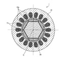
- FIG. 1 is a cross-sectional view showing an example of the configuration of the motor according to the embodiment.
- the motor 1 includes a stator 10 having a tubular shape, and a rotor 20 provided inside the stator 10 and rotating about a central axis C of the stator 10. That is, the central axis of the stator 10 and the central axis of the rotor 20 coincide with each other, and the central axes of the stator 10 and the rotor 20 are hereinafter referred to as C.
- the stator 10 has a plurality of teeth 10a projecting inward and a winding 12 wound around the teeth 10a.
- the rotor 20 has a cylindrical shape extending along the central axis C. The rotor 20 is arranged with a gap between it and the stator 10.
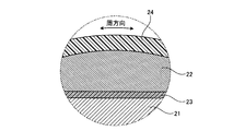
- FIG. 2 is a cross-sectional view showing an example of the configuration of the rotor according to the embodiment
- FIG. 3 is an enlarged view of a region including the iron core, the permanent magnet, and the reinforcing member of FIG.
- the rotor 20 includes a polygonal columnar iron core 21, a permanent magnet 22 arranged on each side surface 21a of the iron core 21 parallel to the central axis C, and an adhesive layer 23 for adhering the permanent magnet 22 to each side surface 21a of the iron core 21. It has a reinforcing member 24 that covers the outer surface of the permanent magnet 22 adhered to the iron core 21.
- the central axis of the iron core 21 coincides with the central axis C of the rotor 20. In the following, the central axis of the iron core 21 is also referred to as C.
- the iron core 21 has a polygonal columnar shape extending along the central axis C of the rotor 20. It is desirable that the cross section of the iron core 21 perpendicular to the central axis C has a regular polygon so that the rotor 20 can rotate stably without causing imbalance.
- the cross section of the iron core 21 perpendicular to the central axis C has a regular hexagon, but it can be any polygon. This is just an example, and the shape of the iron core 21 is appropriately set to a shape capable of obtaining the magnetism required for the rotor 20 and maintaining the strength.
- the permanent magnet 22 has a flat surface 22a arranged on the iron core 21 side, a top surface 22b convex toward the outside in the radial direction of the iron core 21, and a side surface 22c connecting the flat surface 22a and the top surface 22b.
- the permanent magnets 22 are arranged on the side surface 21a of the iron core 21 at equal intervals along the circumferential direction of the rotor 20.
- the contour connecting the outer surfaces of the permanent magnets 22 adhered to each side surface 21a of the iron core 21 is a perfect circle.
- the top surface 22b of the permanent magnet 22 has a circular arc shape that is convex outward in the radial direction, and the cross section of the permanent magnet 22 perpendicular to the central axis C has a D shape.
- the shape of the permanent magnet 22 is not limited to the shape shown in FIG. 2, and may be appropriately set as long as it has a shape that can obtain the magnetism required for operating the motor 1.
- the adhesive layer 23 adheres between the flat surface 22a of the permanent magnet 22 and the side surface 21a of the iron core 21 to fix the permanent magnet 22 to the iron core 21.
- a material having a large breaking elongation as compared with the reinforcing member 24 and having a low elastic modulus as compared with the reinforcing member 24 is selected.
- the reinforcing member 24 covers the outer surface of the permanent magnet 22 adhered to the side surface 21a of the iron core 21 and has a tubular shape.
- the reinforcing member 24 is made of a material having a small elongation at break and a high elastic modulus as compared with the adhesive layer 23.
- the reinforcing member 24 is provided in contact with the top surface 22b of the permanent magnet 22, but the reinforcing member 24 may be arranged at a distance from the top surface 22b of the permanent magnet 22. ..
- it is desirable that the reinforcing member 24 is provided so as to come into contact with the top surface 22b of the permanent magnet 22 in a stationary state.
- the reinforcing member 24 is a fiber reinforced plastic that is formed into a cylindrical shape and at least a part of the fibers is oriented in the circumferential direction of the cylindrical shape.
- the fiber reinforced plastic is composed of fibers and resins, and may be appropriately blended with fillers or additives.
- the elastic modulus in the circumferential direction of the fiber-reinforced plastic in which at least a part of the fibers is oriented in the circumferential direction of the cylinder is higher than the elastic modulus in the circumferential direction of the cylindrical plastic.
- the permanent magnet 22 is suppressed inside in the radial direction by the tensile stress generated in the circumferential direction of the fiber-reinforced plastic. A force is generated, and the permanent magnet 22 can be fixed to the iron core 21.
- the permanent magnet 22 is adhered to the iron core 21 on the flat surface 22a, and the outside of the permanent magnet 22 is made of a fiber reinforced plastic in which a part of the fiber is oriented in the circumferential direction of a cylinder.
- the reinforcing member 24 covers the structure. Therefore, the permanent magnet 22 can be fixed to the rotor 20 without requiring an adhesive force against the moment of inertia generated when the rotation of the rotor 20 is accelerated or decelerated.
- the reinforcing member 24 is made of a fiber reinforced plastic in which at least a part of the fibers is oriented in the circumferential direction of a cylinder.
- a fiber having a large tensile elastic modulus as compared with stainless steel and a small breaking elongation as compared with the adhesive layer 23 used is used as the fiber.
- the tensile modulus of stainless steel is 180 GPa to 220 GPa. Since the minimum value of the elongation at break of the material used as the adhesive layer 23 is about 10%, it is desirable to use a fiber having an elongation at break of less than 10%.
- Such fibers are glass fibers, carbon fibers, SiC fibers, aramid fibers, and boron fibers.
- carbon fibers capable of achieving higher elasticity as fibers, and among the carbon fibers, those having a higher elastic modulus and a smaller elongation at break are desirable.
- an anisotropic pitch-based carbon fiber having a tensile elastic modulus of 620 GPa, a breaking elongation of 0.6%, and a tensile strength of 3430 MPa can be used as the fiber.
- the fiber reinforced plastic are anisotropic pitch carbon fibers, high strength and low elongation at break can be realized.
- a fiber reinforced plastic made of such anisotropic pitch-based carbon fiber has a tensile elastic modulus of 400 GPa or more, a breaking elongation of 0.6%, a tensile strength of 1800 MPa or more, and a high elastic modulus. Since it has, it is suitable for pressing the permanent magnet 22 inward in the radial direction when the rotor 20 rotates. Further, by orienting the fibers in the circumferential direction of the cylinder, it is possible to realize a fiber reinforced plastic having high mechanical properties, particularly high elastic modulus in the circumferential direction of the cylinder.
- the fiber it is desirable to use a fiber having a fiber length of 1 mm or more.
- chopped fibers having a fiber length of 1 mm or more and 30 mm or less are used, the destruction of the fiber reinforced plastic is independent of the resin and is dominated by the strength of the fibers.
- continuous fibers in which the fibers are long connected in the circumferential direction are used, it is desirable because the strength and elastic modulus of the fiber reinforced plastic can be increased.
- the length of the fiber is equal to or greater than the length of the contour of the outer surface of the permanent magnet 22 adhered to the iron core 21 in the cross section perpendicular to the central axis C.
- the tensile elastic modulus in the circumferential direction of the cylindrical fiber reinforced plastic cannot be increased as compared with stainless steel, and the breaking elongation can be reduced as compared with the adhesive layer 23. It is not desirable because it may not be available.
- the fibers are oriented in the circumferential direction of the cylinder.
- the "circumferential direction” refers to a direction of 90 degrees or ⁇ 90 degrees with respect to the central axis C of the rotor 20.
- the present embodiment not only in the direction of 90 degrees or ⁇ 90 degrees with respect to the central axis C, but also in the direction of 90 degrees or ⁇ 90 degrees with respect to the central axis C within a range that does not impair productivity. Even if the fiber is tilted, it is treated as if it is oriented in the circumferential direction.
- the fibers are oriented in the range of 80 to 90 degrees or -80 degrees to -90 degrees with respect to the central axis C, they are treated as being arranged in the circumferential direction. This is because, in the manufacture of the rotor 20, the fibers are often arranged so as to intersect the central axis C in the range of 80 to 90 degrees or -80 degrees to ⁇ 90 degrees.
- the central axis C can be increased as in the case where the fibers are arranged in the direction of 90 degrees or ⁇ 90 degrees with respect to the relative.
- the fibers intersect the central axis C in a range of 80 to 90 degrees or -80 degrees to -90 degrees. Be placed.
- the fibers may be oriented in a plurality of directions so as to have a cylindrical fiber oriented in the circumferential direction and a fiber oriented in another direction intersecting the circumferential direction.
- An example of a direction that intersects in the circumferential direction is the direction of the central axis C or the direction inclined by 45 degrees with respect to the central axis C.
- the orientation direction of the fibers is set so that the tensile elastic modulus in the circumferential direction of the fiber reinforced plastic is larger than the tensile elastic modulus of the stainless steel.
- the tensile elastic modulus in the circumferential direction of the fiber reinforced plastic becomes larger than the tensile elastic modulus in the stainless steel, and the reinforcing member 24 is made of stainless steel.
- the reinforcing member 24 is made of stainless steel.
- a reinforcing effect of the permanent magnet 22 that cannot be realized can be obtained.
- the fibers are oriented in a direction other than the circumferential direction, a fiber reinforced plastic having excellent mechanical properties can be obtained against stresses other than the circumferential direction.
- the reinforcing member 24 is made of fiber reinforced plastic in which all the fibers are anisotropic pitch carbon fibers and the fibers are oriented in the direction of +88 degrees or ⁇ 88 degrees with respect to the central axis C of the rotor 20. Listed in. In this way, since all the fibers having high elasticity and low breaking elongation are intentionally directed in the circumferential direction, the elastic modulus and strength in the circumferential direction are higher, and the amount of movement of the permanent magnet 22 is smaller. Even in this case, the permanent magnet 22 can be held by the iron core 21 by the reinforcing member 24.
- a fiber reinforced plastic using one kind of fiber is exemplified, but a plurality of fibers, for example, carbon fiber and glass fiber, may be combined to form a fiber reinforced plastic.
- the material is selected so as to give the specified performance.
- the resin is selected from the group of epoxy resin, vinyl ester, unsaturated polyester, furan, polyurethane, polyimide, polyamide, polyetheretherketone, polyethersulfone, polypropylene, polyester, polycarbonate, acrylonitrile styrene, acrylonitrile butadiene styrene and modified polyphenylene ether. Will be done.
- the resin is preferably an epoxy resin.
- an additive or a filler may be mixed with the resin so that a predetermined performance is imparted to the reinforcing member 24.
- the adhesive layer 23 is a cured adhesive applied between the iron core 21 and the permanent magnet 22.
- a material having a higher elongation at break than the fiber reinforced plastic and a lower elastic modulus than the fiber reinforced plastic is selected.
- an adhesive layer 23 containing an acrylic resin as a main component or an elastomer-based adhesive layer 23 is desirable.
- the adhesive layer 23 containing an acrylic resin as a main component can achieve a breaking elongation of 10% or more and 50% or less.
- the elastomer-based adhesive layer 23 can have a larger breaking elongation than the adhesive layer 23 containing an acrylic resin as a main component.
- the adhesive layer 23 has a breaking elongation of 10% or more, it is desirable that the breaking elongation of the fiber reinforced plastic is less than 10%.
- the thermosetting resin-based elastomer can strengthen the adhesive force with the permanent magnet 22 and the iron core 21.
- thermosetting resin-based elastomers examples include urethane resin, fluororesin, modified silicone resin, or silicone resin as the main component.
- the silicone resin has good heat resistance and chemical resistance, and can achieve 100% to 690% elongation at break.
- Silicone resin is a material that is superior in chemical resistance and oxidative deterioration as compared with other resins, and can increase elongation at break.
- the adhesive layer 23 mainly composed of an epoxy resin having a breaking elongation of less than 10%, the adhesive layer 23 breaks before the fiber reinforced plastic reaches the breakage. For example, if the adhesive layer 23 of one of the six permanent magnets 22 breaks while the rotor 20 of FIG. 2 is rotating, an imbalance occurs and the rotor 20 is destroyed. Therefore, it is desirable to use the adhesive layer 23 having a breaking elongation of 10% or more.
- an adhesive in which an epoxy resin is dispersed in a modified silicone resin an adhesive layer 23 having an increased adhesive strength at the interface can be obtained. Further, the elongation at break can be increased by making the adhesive layer 23 porous.
- the adhesive layer is formed until the fiber reinforced plastic having a small breaking elongation breaks. 23 does not break. That is, the destruction of the rotor 20 does not depend on the portion where the strength of the adhesive layer 23 is weak, and the permanent magnet 22 can be fixed to the iron core 21 by utilizing the high strength of the fiber reinforced plastic in the circumferential direction.
- the permanent magnet 22 is evenly and minutely displaced in the radial direction of the cylinder by the centrifugal force acting on the permanent magnet 22 toward the outside in the radial direction of the rotor 20.
- the adhesive layer 23 having a breaking elongation larger than that of the fiber reinforced plastic is not broken, and the permanent magnet 22 is pressed against the fiber reinforced plastic. Then, the tensile stress generated in the circumferential direction of the fiber reinforced plastic generates a force to hold it inward in the radial direction, and the permanent magnet 22 is fixed by the fiber reinforced plastic. Therefore, the permanent magnet 22 is held by the strength of the fiber reinforced plastic rather than by the strength of the adhesive layer 23. That is, the holding of the permanent magnet 22 by the adhesive layer 23 is reinforced by the fiber reinforced plastic.
- the thickness of the adhesive layer 23 will be described.
- impact resistance is added to the adhesive layer 23. Specifically, when the thickness of the adhesive layer 23 is 0.05 mm or more, the adhesive layer 23 has impact resistance.
- the shear strength of the adhesive surface is improved. Specifically, it is known that the shear strength is improved when the thickness of the adhesive layer 23 is 0.5 mm or less.
- the outer diameter of the rotor 20 is set according to the target motor 1 or generator. For example, from a small motor 1 used for a vacuum cleaner or a toy having a rotor 20 having an outer diameter of about 10 mm to a large motor 1 used for a power plant having a rotor 20 having an outer diameter of about 4.6 m in diameter. Rotors 20 of various sizes are used up to the generator. The outer diameter between these includes, for example, a rotor 20 of 25 mm or more and 160 mm or less used for a starter motor of an automobile, a rotor 20 of 80 mm or more and 400 mm or less used for a drive motor of an electric vehicle, and NC (Numerical Control). ) There are rotors 20 of 80 mm or more and 200 mm or less used for spindle motors of processing machines, rotors 20 of 120 mm or more and 3 m or less used for generators for wind power generation, and the like.
- the ratio of the breaking elongation of the fibers oriented in the circumferential direction of the fiber reinforced plastic having a tubular shape to the breaking elongation of the adhesive layer 23 is 2 of the thickness of the adhesive layer 23 with respect to the outer diameter of the rotor 20. It will be less than double. That is, the relationship between the breaking elongation ⁇ a of the adhesive layer 23 and the breaking elongation ⁇ f of the fibers oriented in the circumferential direction of the fiber reinforced plastic is determined by using the outer diameter D of the rotor 20 and the thickness t of the adhesive layer 23. It is required to satisfy the following equation (1).
- the rotor 20 according to the present embodiment cannot be produced by the filament winding method.
- Carbon fibers having a breaking elongation ⁇ f of 0.3% or more and 2.4% or less have been put into practical use in industrial applications (for example, FRP Structural Design Handbook, Masuji Uemura et al., Reinforced Plastics Association, 1994, p.6-12).
- anisotropic pitch-based carbon fibers capable of realizing the breaking elongation ⁇ f of the cylindrical fiber reinforced plastic oriented in the circumferential direction in the range of 0.3% or more and 1.1% or less are desirable.
- an anisotropic pitch-based carbon fiber having a breaking elongation ⁇ f of 0.3% is used.
- the permanent magnet 22 is adhered to the iron core 21 with the following adhesives A, B, C, D, E, F, and G, and the anisotropic pitch-based carbon fiber impregnated with the resin is bonded to the iron core 21 by the filament winding method.
- a molding test is carried out in which the permanent magnet 22 is wound around the outer surface of the adhered permanent magnet 22.
- the rotor 20 can be satisfactorily molded by the filament winding method.
- the permanent magnet 22 is adhered with the adhesive of G, the permanent magnet 22 falls off from the iron core 21 due to the force when the fiber is wound, and the rotor 20 is formed by the filament winding method. I can't. From the above, the critical value is obtained when ⁇ f is 0.3% and ⁇ a is 690%. That is, when ⁇ f / ⁇ a of the following equation (4) is satisfied, the rotor 20 according to the present embodiment can be molded by the filament winding method. Then, the equation (1) is derived from the equations (2) and (4).
- the shaft runout generated when the rotation speed of the rotor 20 is accelerated or decelerated becomes large, which may lead to contact with the stator 10.
- the ratio of the thickness t of the adhesive layer 23 in the rotor 20 to the outer diameter D of the rotor 20 to 1/150 or less, no further axial runout occurs. Since the straight line extending in the radial direction intersects the outer circumference of the rotor 20 at two places, the adhesive layer 23 also intersects with this straight line at two places. That is, the outer diameter of the rotor 20 includes the thickness of the two adhesive layers 23. Therefore, the relationship as shown in the following equation (5) is derived. As a result, the gap between the rotor 20 and the stator 10 in the motor 1 can be narrowed.
- Equation (6) is obtained by the equations (1) and (5). That is, the relationship between the breaking elongation ⁇ a of the adhesive layer 23, the breaking elongation ⁇ f of the fibers oriented in the circumferential direction of the fiber reinforced plastic, the thickness t of the adhesive layer 23, and the outer diameter D of the rotor 20 is in equation (6).
- the above-mentioned structure of the fiber reinforced plastic and the adhesive layer 23 can prevent the adhesive layer 23 from being broken before the fiber reinforced plastic is broken.
- the thickness t of the adhesive layer 23 In order for the relationship between the thickness t of the adhesive layer 23 and the outer diameter D of the rotor 20 to satisfy the equation (6), 1/4600 or more of the outer diameter D of the rotor 20 is contained in the adhesive layer 23.
- a filler having an average particle size of 1/150 or less may be dispersed. As a result, the thickness t of the adhesive layer 23 can be reduced to 1/150 or less at 1/4600 or more of the outer diameter D of the rotor 20.
- FIG. 4 is a flowchart showing an example of the procedure of the rotor manufacturing method according to the embodiment.
- the permanent magnet 22 is adhered to the side surface 21a of the iron core 21 parallel to the central axis C via the adhesive layer 23 (step S11). Specifically, the side surface 21a of the iron core 21 parallel to the central axis C and the flat surface 22a of the permanent magnet 22 are adhered with an adhesive, and the adhesive is cured to form the adhesive layer 23. As a result, the permanent magnet 22 is adhered to the side surface 21a of the iron core 21 parallel to the central axis C. Further, permanent magnets 22 are arranged at equal intervals on the side surface 21a of the iron core 21 along the circumferential direction of the rotor 20. As shown in FIG.
- the outer surface is composed of all the permanent magnets 22 adhered to the iron core 21 in the cross section perpendicular to the central axis C.
- the contour of the surface has a perfect circular shape.
- the target thickness is in the range of 1/4600 or more and 1/150 or less of the outer diameter D of the rotor 20.
- an acrylic resin-based adhesive or an elastomer-based adhesive is used as the adhesive.
- the elastomer-based adhesive one containing urethane resin, fluororesin, modified silicone resin or silicone resin as a main component is used.
- the fibers are impregnated with the uncured resin (step S12).
- the fibers may be composed of bundles.
- glass fiber, carbon fiber, SiC fiber, aramid fiber, and boron fiber are used as the fiber.
- the resins are epoxy resin, vinyl ester, unsaturated polyester, furan, polyurethane, polyimide, polyamide, polyetheretherketone, polyethersulfone, polypropylene, polyester, polycarbonate, acrylonitrile styrene, acrylonitrile butadiene styrene and modified polyphenylene. Selected from the group of ethers.
- the fiber impregnated with the uncured resin is directly wound around the entire outer surface of the permanent magnet 22 adhered to the iron core 21 (step S13). Then, the resin impregnated in the fibers wound around the permanent magnet 22 is cured (step S14).
- the iron core 21 to which the permanent magnet 22 is adhered and the fibers are wound around the outer surface of the permanent magnet 22 is heated by a heating device such as an oven to cure the resin.
- a cylindrical reinforcing member 24 made of fiber reinforced plastic is formed so as to cover the outer surface of the permanent magnet 22.
- the rotor 20 is manufactured.
- a step of processing the outer shape of the iron core 21 to which the permanent magnet 22 is adhered may be provided according to the desired shape.
- the iron core 21 to which the permanent magnet 22 is adhered is fitted into the tubular fiber reinforced plastic by press-fitting or cooling fitting.
- the rotor 20 may be damaged by the press-fitting, and in the case of cold fitting, the rotor 20 may be damaged by the heat shock.
- the manufacturing method of the present embodiment described above the possibility of damage to the rotor 20 can be reduced. That is, it is possible to provide a method for manufacturing the rotor 20 having excellent productivity.
- the outer diameter D of the rotor 20 is 40 mm.
- An adhesive composed of a silicone resin having a breaking elongation ⁇ a of 160% and a tensile elastic modulus of 45.8 MPa is used. Glass beads having an average particle size of 100 ⁇ m and a standard deviation of 5 ⁇ m are dispersed as a filler in the adhesive. The filler is 2 wt. Dispersed in the adhesive at a rate of%.
- the thickness t of the adhesive layer 23 is controlled to 100 ⁇ m.
- the permanent magnet 22 is adhered to the side surface 21a parallel to the central axis C of the iron core 21.
- the iron core 21 to which the permanent magnet 22 is adhered has a cylindrical shape.
- the reinforcing member 24 which is a continuous fiber of anisotropic pitch-based carbon fiber.
- the breaking elongation ⁇ f of the fiber is 0.6%, and the tensile elastic modulus is 600 GPa.
- a bundle of 3000 fibers is used. Further, the bundled fibers are impregnated with an uncured resin in which bisphenol A type epoxy and acid anhydride are mixed in a predetermined composition. Then, using the filament winding method, the fiber is directly wound around the outer surface of the permanent magnet 22 bonded to the iron core 21 by the adhesive layer 23.
- the feed pitch of the winding is 3 mm per winding.
- a reinforcing member 24 made of a cylindrical fiber reinforced plastic is formed.
- the orientation angle of the fibers is +89 degrees or ⁇ 89 degrees with respect to the central axis C of the rotor 20.
- the thickness of the fiber reinforced plastic is 1 mm.
- the ratio of the outer diameter D of the rotor 20 to the thickness t of the adhesive layer 23 is represented by the following equation (8). Since the radial straight line in the cross section perpendicular to the central axis C of the rotor 20 intersects the two adhesive layers 23, the equation (8) becomes the following equation (9).
- both ⁇ f / ⁇ a obtained by Eq. (7) and 2 t / D obtained by Eq. (9) satisfy the relationship of Eq. (6) described above. That is, since the fiber reinforced plastic is the starting point of destruction when the rotor 20 is rotated, the fiber reinforced plastic has a reinforcing effect of holding the permanent magnet 22 on the outer circumference of the iron core 21. At the same time, when the rotor 20 is manufactured by the filament winding method, the permanent magnet 22 does not fall off, and the structure shown in FIG. 2 can be realized. Further, since the filler having a desired average particle size is dispersed in the adhesive layer 23, the thickness of the adhesive layer 23 can be easily controlled. By manufacturing by the filament winding method, the step of press-fitting or cooling and fitting becomes unnecessary, and the rotor 20 can be manufactured by a manufacturing method having excellent productivity.
- the rotor 20 manufactured by this manufacturing method is subjected to thermal stress during molding in a stationary state, but the fiber reinforced plastic is pulled by an intentional pressure as in the case where the rotor 20 is manufactured by press-fitting or cooling fitting. Absent. Therefore, the absolute value of the tensile strain in the circumferential direction of the surface of the cylindrical fiber reinforced plastic is 300 ⁇ or less. If the absolute value of the tensile strain in the circumferential direction of the surface of the cylindrical fiber reinforced plastic is larger than 300 ⁇ , it means that it is subjected to thermal stress during molding, as in the case of manufacturing by press fitting or cold fitting. Conceivable. That is, a cylindrical fiber reinforced plastic having an absolute value of tensile strain in the circumferential direction of 300 ⁇ or less cannot be manufactured by press fitting or cold fitting.
- the breaking elongation ⁇ a of the adhesive layer 23 is determined in accordance with JIS (Japanese Industrial Standards) K716-11994 (ISO (International Organization for Standardization) 527-1) or JIS K7127-1999. is there. If the adhesive layer 23, which is a test piece, cannot be manufactured with dimensions conforming to the above standards, it may be considered to be equivalent to this even if it is measured using a test piece having a similar shape.
- the breaking elongation ⁇ f of the fiber is obtained in accordance with the method of JIS R 7606-2000. Even when it is necessary to take out the fiber from the fiber reinforced plastic, among the combustion method, the nitrate decomposition method, and the sulfate decomposition method described in "7. Measurement of the mass of carbon fiber" of JIS K 7075-1991, the fiber The fibers may be extracted by any method that does not damage the fibers. Even if the length of the fiber cannot be produced in a size conforming to the above standard, it may be measured using a test piece having a similar shape.
- the breaking elongation ⁇ a of the adhesive layer 23 and the breaking elongation ⁇ f of the fiber referred to here are those measured at the environmental temperature when the rotor 20 is operated or at a temperature of 23 ° C. when it is unknown.
- the iron core 21 and the permanent magnet 22 are bonded to each other by the adhesive layer 23 having a breaking elongation of ⁇ a, and the rotor 20 is attached to the outer surface of the permanent magnet 22 bonded to the iron core 21.
- It has a structure in which a cylindrical fiber reinforced plastic having fibers having a breaking elongation of ⁇ f is wound.
- fiber reinforced plastics at least some fibers are oriented in the circumferential direction of the cylinder.
- the fiber reinforced plastic is broken before the adhesive layer 23 is broken when the rotor 20 is rotated. That is, the starting point of destruction is fiber reinforced plastic. Therefore, until the fiber-reinforced plastic is destroyed, the fiber-reinforced plastic can provide a reinforcing effect of firmly holding the permanent magnet 22 in the iron core 21.
- the fibers are wound around the permanent magnet 22 without falling off by the filament winding method during the production of the rotor 20. be able to.
- an elastomer adhesive layer 23 capable of achieving a breaking elongation ⁇ a of 10% or more, which is larger than the breaking elongation ⁇ f of the fiber reinforced plastic, may be used. Further, the adhesive layer 23 having a breaking elongation ⁇ a of 100% or more and 690% or less may be used. With these configurations, the permanent magnet 22 can be firmly fixed to the iron core 21 with the fiber reinforced plastic during the rotation of the rotor 20, and the fiber reinforced plastic can be used as the starting point of fracture. At the same time, the fibers can be wound around the outer surface of the permanent magnet 22 without the permanent magnet 22 falling off during the manufacture of the rotor 20.
- the thickness t of the adhesive layer 23 is controlled to a desired thickness by using an adhesive in which a filler having an average particle size of 1/4600 or more and 1/150 or less of the outer diameter D of the rotor 20 is dispersed. be able to.
- the fiber reinforced plastic carbon fiber reinforced plastic in which more than half of the fibers are anisotropic pitch carbon fibers may be used.
- a carbon fiber reinforced plastic in which more than half of the fibers have carbon fibers oriented in the circumferential direction of a cylinder may be used.
- the breaking elongation ⁇ f of the fiber oriented in the circumferential direction of the fiber reinforced plastic can be realized in the range of 0.3% or more and 1.1% or less.
- the carbon fiber reinforced plastic becomes the starting point of fracture during rotation, and the reinforcing effect of fixing the permanent magnet 22 to the iron core 21 by the carbon fiber reinforced plastic can be obtained.
- the bonding the permanent magnet 22 to the core 21 by adhesive layer 23 elongation at break is epsilon a
- elongation at break impregnated with resin is impregnated with resin as a epsilon f fibers
- the rotor 20 is manufactured by winding it around the surface of the permanent magnet 22 and curing the resin.
- damage during manufacturing of the rotor 20 can be suppressed as compared with the case where the cylindrical fiber reinforced plastic is fitted into the iron core 21 to which the permanent magnet 22 is adhered by using the press-fitting or cooling fitting method. ..
- the productivity of manufacturing the rotor 20 can be improved as compared with the case where the cylindrical fiber reinforced plastic is fitted into the iron core 21 to which the permanent magnet 22 is adhered by press-fitting or cooling fitting.
- the rotor 20 of the motor 1 is taken as an example, but the present embodiment is not limited to the motor 1, and may be applied to the rotor 20 of the generator. In this case as well, the same effect can be obtained with the same configuration.
- the configuration shown in the above-described embodiment shows an example of the content of the present invention, can be combined with another known technique, and is one of the configurations without departing from the gist of the present invention. It is also possible to omit or change the part.
Landscapes
- Engineering & Computer Science (AREA)
- Power Engineering (AREA)
- Manufacturing & Machinery (AREA)
- Permanent Field Magnets Of Synchronous Machinery (AREA)
- Manufacture Of Motors, Generators (AREA)
Abstract
La présente invention concerne un rotor (20) comprenant : un noyau en fer (21) ; une pluralité d'aimants permanents (22) qui sont liés à une surface latérale (21a) du noyau en fer (21) au moyen d'une couche adhésive (23), ladite surface latérale étant parallèle à l'axe central (C) du noyau en fer (21) ; et un élément de renfort (24), de forme cylindrique, qui est disposé sur la surface externe de la pluralité d'aimants permanents (22) liés à la surface latérale (21a) du noyau en fer (21). L'élément de renfort (24) est composé d'une matière plastique renforcée de fibres, certaines fibres étant orientées dans la direction circonférentielle de la forme cylindrique. Ce rotor est caractérisé en ce que le rapport entre l'allongement à la rupture des fibres orientées dans la direction circonférentielle de la matière plastique renforcée de fibres de forme cylindrique et l'allongement à la rupture de la couche adhésive (23) ne dépasse pas deux fois le rapport entre l'épaisseur (t) de la couche adhésive (23) et le diamètre extérieur (D) du rotor (20).
Priority Applications (5)
| Application Number | Priority Date | Filing Date | Title |
|---|---|---|---|
| PCT/JP2019/027478 WO2021005774A1 (fr) | 2019-07-11 | 2019-07-11 | Rotor, moteur et procédé de production de rotor |
| DE112019007538.1T DE112019007538T5 (de) | 2019-07-11 | 2019-07-11 | Rotor, motor und verfahren zur herstellung eines rotors |
| JP2019558650A JP6639761B1 (ja) | 2019-07-11 | 2019-07-11 | ロータおよびモータ |
| CN201980098250.4A CN114072989B (zh) | 2019-07-11 | 2019-07-11 | 转子及电动机 |
| TW109114764A TWI747266B (zh) | 2019-07-11 | 2020-05-04 | 轉子及馬達 |
Applications Claiming Priority (1)
| Application Number | Priority Date | Filing Date | Title |
|---|---|---|---|
| PCT/JP2019/027478 WO2021005774A1 (fr) | 2019-07-11 | 2019-07-11 | Rotor, moteur et procédé de production de rotor |
Publications (1)
| Publication Number | Publication Date |
|---|---|
| WO2021005774A1 true WO2021005774A1 (fr) | 2021-01-14 |
Family
ID=69320898
Family Applications (1)
| Application Number | Title | Priority Date | Filing Date |
|---|---|---|---|
| PCT/JP2019/027478 Ceased WO2021005774A1 (fr) | 2019-07-11 | 2019-07-11 | Rotor, moteur et procédé de production de rotor |
Country Status (5)
| Country | Link |
|---|---|
| JP (1) | JP6639761B1 (fr) |
| CN (1) | CN114072989B (fr) |
| DE (1) | DE112019007538T5 (fr) |
| TW (1) | TWI747266B (fr) |
| WO (1) | WO2021005774A1 (fr) |
Cited By (2)
| Publication number | Priority date | Publication date | Assignee | Title |
|---|---|---|---|---|
| WO2023095424A1 (fr) * | 2021-11-29 | 2023-06-01 | 東レ株式会社 | Dispositif de fabrication et procédé de formage pour matière plastique renforcée par des fibres de carbone de renforcement de composant rotatif |
| US20230179045A1 (en) * | 2020-05-04 | 2023-06-08 | Tesla, Inc. | Permanent magnet motor with wrapping |
Families Citing this family (2)
| Publication number | Priority date | Publication date | Assignee | Title |
|---|---|---|---|---|
| US11689074B2 (en) * | 2020-10-29 | 2023-06-27 | GM Global Technology Operations LLC | Rotary electric machine with adhesive-reinforced rotor |
| TWI868900B (zh) * | 2023-09-05 | 2025-01-01 | 凱泓機械股份有限公司 | 一種轉子磁石之高速離心脫拔測試方法 |
Citations (4)
| Publication number | Priority date | Publication date | Assignee | Title |
|---|---|---|---|---|
| JPS611246A (ja) * | 1984-06-11 | 1986-01-07 | Matsushita Electric Ind Co Ltd | 永久磁石回転子 |
| JP2006081360A (ja) * | 2004-09-13 | 2006-03-23 | Yaskawa Electric Corp | ロータ表面へのマグネット接着装置 |
| JP2013188005A (ja) * | 2012-03-07 | 2013-09-19 | Mitsubishi Electric Corp | 磁石取付型回転子 |
| JP2019071763A (ja) * | 2017-10-05 | 2019-05-09 | ファナック株式会社 | 回転子、回転電機及び被覆筒の製造方法 |
Family Cites Families (11)
| Publication number | Priority date | Publication date | Assignee | Title |
|---|---|---|---|---|
| DE69839927D1 (de) * | 1997-10-13 | 2008-10-02 | Matsushita Electric Industrial Co Ltd | Motor mit innerem Permanentmagnetrotor |
| JP2005312250A (ja) | 2004-04-26 | 2005-11-04 | Meidensha Corp | 永久磁石式回転電機の磁石固定方法 |
| JP4736028B2 (ja) * | 2005-07-01 | 2011-07-27 | 株式会社安川電機 | 回転子とその製造方法および電動機 |
| JP2013230047A (ja) * | 2012-04-26 | 2013-11-07 | Ichinomiya Denki:Kk | モータ用ロータ、及びモータ |
| CN104685764B (zh) * | 2012-09-28 | 2017-12-01 | 大金工业株式会社 | 转子及旋转电气设备 |
| WO2014156090A1 (fr) * | 2013-03-25 | 2014-10-02 | パナソニック株式会社 | Moteur électrique à aimant permanant intégré et son procédé de fabrication |
| CN104917316A (zh) * | 2014-03-12 | 2015-09-16 | 精工爱普生株式会社 | 转子以及马达 |
| CN104158325B (zh) * | 2014-08-21 | 2017-06-27 | 江西工埠机械有限责任公司 | 外转子电机的永磁体安装结构 |
| JP6087427B2 (ja) * | 2014-10-02 | 2017-03-01 | 三菱電機株式会社 | 回転電機の回転子及び回転電機の回転子の製造方法 |
| WO2017047253A1 (fr) * | 2015-09-16 | 2017-03-23 | 三菱電機株式会社 | Rotor destiné à une machine électrique rotative, et machine électrique rotative |
| CN109546775B (zh) * | 2018-12-26 | 2024-11-19 | 河南森源重工有限公司 | 内嵌式无磁桥转子及永磁电机 |
-
2019
- 2019-07-11 DE DE112019007538.1T patent/DE112019007538T5/de not_active Withdrawn
- 2019-07-11 WO PCT/JP2019/027478 patent/WO2021005774A1/fr not_active Ceased
- 2019-07-11 JP JP2019558650A patent/JP6639761B1/ja active Active
- 2019-07-11 CN CN201980098250.4A patent/CN114072989B/zh active Active
-
2020
- 2020-05-04 TW TW109114764A patent/TWI747266B/zh active
Patent Citations (4)
| Publication number | Priority date | Publication date | Assignee | Title |
|---|---|---|---|---|
| JPS611246A (ja) * | 1984-06-11 | 1986-01-07 | Matsushita Electric Ind Co Ltd | 永久磁石回転子 |
| JP2006081360A (ja) * | 2004-09-13 | 2006-03-23 | Yaskawa Electric Corp | ロータ表面へのマグネット接着装置 |
| JP2013188005A (ja) * | 2012-03-07 | 2013-09-19 | Mitsubishi Electric Corp | 磁石取付型回転子 |
| JP2019071763A (ja) * | 2017-10-05 | 2019-05-09 | ファナック株式会社 | 回転子、回転電機及び被覆筒の製造方法 |
Cited By (3)
| Publication number | Priority date | Publication date | Assignee | Title |
|---|---|---|---|---|
| US20230179045A1 (en) * | 2020-05-04 | 2023-06-08 | Tesla, Inc. | Permanent magnet motor with wrapping |
| WO2023095424A1 (fr) * | 2021-11-29 | 2023-06-01 | 東レ株式会社 | Dispositif de fabrication et procédé de formage pour matière plastique renforcée par des fibres de carbone de renforcement de composant rotatif |
| CN118103197A (zh) * | 2021-11-29 | 2024-05-28 | 东丽株式会社 | 旋转部件加强用碳纤维增强塑料的制造装置及成形方法 |
Also Published As
| Publication number | Publication date |
|---|---|
| CN114072989A (zh) | 2022-02-18 |
| DE112019007538T5 (de) | 2022-03-31 |
| JP6639761B1 (ja) | 2020-02-05 |
| JPWO2021005774A1 (ja) | 2021-09-13 |
| TWI747266B (zh) | 2021-11-21 |
| CN114072989B (zh) | 2024-11-29 |
| TW202103409A (zh) | 2021-01-16 |
Similar Documents
| Publication | Publication Date | Title |
|---|---|---|
| JP6639761B1 (ja) | ロータおよびモータ | |
| JP6592230B2 (ja) | 磁石浮上り及び飛散防止部材並びにロータ | |
| CN206673717U (zh) | 保持构件、转子以及旋转电机 | |
| JP6800323B2 (ja) | Spmモータ回転子およびその製造方法 | |
| CN107002817A (zh) | 用于储能的飞轮 | |
| EP4050769A1 (fr) | Manchon de rotor de machine électrique | |
| JP7476968B2 (ja) | ロータ、モータ、及びロータの製造方法 | |
| JPH11266555A (ja) | 回転電機の回転子 | |
| KR101430543B1 (ko) | 보강된 자석 | |
| KR20140047080A (ko) | 전기 발전기들에 대한 회전자 엔드벨 | |
| CN105518339B (zh) | 用于储能的飞轮及其制造方法 | |
| GB2504216A (en) | A flywheel for energy storage and a corresponding method of manufacture | |
| US20250088052A1 (en) | Rotor and dynamo-electric machine | |
| JP6981373B2 (ja) | ロータの製造方法 | |
| JP7120503B1 (ja) | モータのロータおよびこのロータを用いたモータ | |
| EP4614770A1 (fr) | Bague protectrice de machine électrique tournante, son procédé de fabrication, machine électrique tournante et équipement de mobilité à entraînement électrique | |
| CN121511544A (zh) | 圆筒部件、带锥部的圆筒部件、表面磁铁型电动机及表面磁铁型电动机的制造方法 | |
| JP2015110303A (ja) | フライホイールとその製造方法 | |
| JP2020043734A (ja) | 回転電機用ステータコアおよび回転電機 |
Legal Events
| Date | Code | Title | Description |
|---|---|---|---|
| ENP | Entry into the national phase |
Ref document number: 2019558650 Country of ref document: JP Kind code of ref document: A |
|
| 121 | Ep: the epo has been informed by wipo that ep was designated in this application |
Ref document number: 19936584 Country of ref document: EP Kind code of ref document: A1 |
|
| 122 | Ep: pct application non-entry in european phase |
Ref document number: 19936584 Country of ref document: EP Kind code of ref document: A1 |