WO2021006096A1 - Dispositif de charnière - Google Patents
Dispositif de charnière Download PDFInfo
- Publication number
- WO2021006096A1 WO2021006096A1 PCT/JP2020/025520 JP2020025520W WO2021006096A1 WO 2021006096 A1 WO2021006096 A1 WO 2021006096A1 JP 2020025520 W JP2020025520 W JP 2020025520W WO 2021006096 A1 WO2021006096 A1 WO 2021006096A1
- Authority
- WO
- WIPO (PCT)
- Prior art keywords
- hinge
- arm
- guide
- sub
- hinge body
- Prior art date
- Legal status (The legal status is an assumption and is not a legal conclusion. Google has not performed a legal analysis and makes no representation as to the accuracy of the status listed.)
- Ceased
Links
Images












Classifications
-
- E—FIXED CONSTRUCTIONS
- E05—LOCKS; KEYS; WINDOW OR DOOR FITTINGS; SAFES
- E05D—HINGES OR SUSPENSION DEVICES FOR DOORS, WINDOWS OR WINGS
- E05D3/00—Hinges with pins
- E05D3/06—Hinges with pins with two or more pins
- E05D3/18—Hinges with pins with two or more pins with sliding pins or guides
-
- E—FIXED CONSTRUCTIONS
- E05—LOCKS; KEYS; WINDOW OR DOOR FITTINGS; SAFES
- E05D—HINGES OR SUSPENSION DEVICES FOR DOORS, WINDOWS OR WINGS
- E05D3/00—Hinges with pins
- E05D3/06—Hinges with pins with two or more pins
- E05D3/18—Hinges with pins with two or more pins with sliding pins or guides
- E05D3/186—Scissors hinges, with two crossing levers and five parallel pins
-
- E—FIXED CONSTRUCTIONS
- E05—LOCKS; KEYS; WINDOW OR DOOR FITTINGS; SAFES
- E05D—HINGES OR SUSPENSION DEVICES FOR DOORS, WINDOWS OR WINGS
- E05D11/00—Additional features or accessories of hinges
- E05D11/08—Friction devices between relatively-movable hinge parts
-
- E—FIXED CONSTRUCTIONS
- E05—LOCKS; KEYS; WINDOW OR DOOR FITTINGS; SAFES
- E05D—HINGES OR SUSPENSION DEVICES FOR DOORS, WINDOWS OR WINGS
- E05D11/00—Additional features or accessories of hinges
- E05D11/08—Friction devices between relatively-movable hinge parts
- E05D11/087—Friction devices between relatively-movable hinge parts with substantially axial friction, e.g. friction disks
-
- E—FIXED CONSTRUCTIONS
- E05—LOCKS; KEYS; WINDOW OR DOOR FITTINGS; SAFES
- E05D—HINGES OR SUSPENSION DEVICES FOR DOORS, WINDOWS OR WINGS
- E05D11/00—Additional features or accessories of hinges
- E05D11/10—Devices for preventing movement between relatively-movable hinge parts
-
- E—FIXED CONSTRUCTIONS
- E05—LOCKS; KEYS; WINDOW OR DOOR FITTINGS; SAFES
- E05F—DEVICES FOR MOVING WINGS INTO OPEN OR CLOSED POSITION; CHECKS FOR WINGS; WING FITTINGS NOT OTHERWISE PROVIDED FOR, CONCERNED WITH THE FUNCTIONING OF THE WING
- E05F1/00—Closers or openers for wings, not otherwise provided for in this subclass
- E05F1/08—Closers or openers for wings, not otherwise provided for in this subclass spring-actuated, e.g. for horizontally sliding wings
- E05F1/10—Closers or openers for wings, not otherwise provided for in this subclass spring-actuated, e.g. for horizontally sliding wings for swinging wings, e.g. counterbalance
- E05F1/12—Mechanisms in the shape of hinges or pivots, operated by springs
-
- E—FIXED CONSTRUCTIONS
- E05—LOCKS; KEYS; WINDOW OR DOOR FITTINGS; SAFES
- E05F—DEVICES FOR MOVING WINGS INTO OPEN OR CLOSED POSITION; CHECKS FOR WINGS; WING FITTINGS NOT OTHERWISE PROVIDED FOR, CONCERNED WITH THE FUNCTIONING OF THE WING
- E05F1/00—Closers or openers for wings, not otherwise provided for in this subclass
- E05F1/08—Closers or openers for wings, not otherwise provided for in this subclass spring-actuated, e.g. for horizontally sliding wings
- E05F1/10—Closers or openers for wings, not otherwise provided for in this subclass spring-actuated, e.g. for horizontally sliding wings for swinging wings, e.g. counterbalance
- E05F1/12—Mechanisms in the shape of hinges or pivots, operated by springs
- E05F1/1284—Mechanisms in the shape of hinges or pivots, operated by springs with a leaf or similar spring
-
- F—MECHANICAL ENGINEERING; LIGHTING; HEATING; WEAPONS; BLASTING
- F16—ENGINEERING ELEMENTS AND UNITS; GENERAL MEASURES FOR PRODUCING AND MAINTAINING EFFECTIVE FUNCTIONING OF MACHINES OR INSTALLATIONS; THERMAL INSULATION IN GENERAL
- F16C—SHAFTS; FLEXIBLE SHAFTS; ELEMENTS OR CRANKSHAFT MECHANISMS; ROTARY BODIES OTHER THAN GEARING ELEMENTS; BEARINGS
- F16C11/00—Pivots; Pivotal connections
- F16C11/04—Pivotal connections
- F16C11/045—Pivotal connections with at least a pair of arms pivoting relatively to at least one other arm, all arms being mounted on one pin
-
- E—FIXED CONSTRUCTIONS
- E05—LOCKS; KEYS; WINDOW OR DOOR FITTINGS; SAFES
- E05D—HINGES OR SUSPENSION DEVICES FOR DOORS, WINDOWS OR WINGS
- E05D2700/00—Hinges or other suspension devices especially for doors or windows
- E05D2700/10—Various door and window fittings, e.g. suspension devices for double hung windows or screens
-
- E—FIXED CONSTRUCTIONS
- E05—LOCKS; KEYS; WINDOW OR DOOR FITTINGS; SAFES
- E05Y—INDEXING SCHEME ASSOCIATED WITH SUBCLASSES E05D AND E05F, RELATING TO CONSTRUCTION ELEMENTS, ELECTRIC CONTROL, POWER SUPPLY, POWER SIGNAL OR TRANSMISSION, USER INTERFACES, MOUNTING OR COUPLING, DETAILS, ACCESSORIES, AUXILIARY OPERATIONS NOT OTHERWISE PROVIDED FOR, APPLICATION THEREOF
- E05Y2201/00—Constructional elements; Accessories therefor
- E05Y2201/40—Motors; Magnets; Springs; Weights; Accessories therefor
- E05Y2201/47—Springs
- E05Y2201/48—Leaf or leg springs
-
- E—FIXED CONSTRUCTIONS
- E05—LOCKS; KEYS; WINDOW OR DOOR FITTINGS; SAFES
- E05Y—INDEXING SCHEME ASSOCIATED WITH SUBCLASSES E05D AND E05F, RELATING TO CONSTRUCTION ELEMENTS, ELECTRIC CONTROL, POWER SUPPLY, POWER SIGNAL OR TRANSMISSION, USER INTERFACES, MOUNTING OR COUPLING, DETAILS, ACCESSORIES, AUXILIARY OPERATIONS NOT OTHERWISE PROVIDED FOR, APPLICATION THEREOF
- E05Y2201/00—Constructional elements; Accessories therefor
- E05Y2201/40—Motors; Magnets; Springs; Weights; Accessories therefor
- E05Y2201/47—Springs
- E05Y2201/484—Torsion springs
-
- E—FIXED CONSTRUCTIONS
- E05—LOCKS; KEYS; WINDOW OR DOOR FITTINGS; SAFES
- E05Y—INDEXING SCHEME ASSOCIATED WITH SUBCLASSES E05D AND E05F, RELATING TO CONSTRUCTION ELEMENTS, ELECTRIC CONTROL, POWER SUPPLY, POWER SIGNAL OR TRANSMISSION, USER INTERFACES, MOUNTING OR COUPLING, DETAILS, ACCESSORIES, AUXILIARY OPERATIONS NOT OTHERWISE PROVIDED FOR, APPLICATION THEREOF
- E05Y2900/00—Application of doors, windows, wings or fittings thereof
- E05Y2900/20—Application of doors, windows, wings or fittings thereof for furniture, e.g. cabinets
-
- E—FIXED CONSTRUCTIONS
- E05—LOCKS; KEYS; WINDOW OR DOOR FITTINGS; SAFES
- E05Y—INDEXING SCHEME ASSOCIATED WITH SUBCLASSES E05D AND E05F, RELATING TO CONSTRUCTION ELEMENTS, ELECTRIC CONTROL, POWER SUPPLY, POWER SIGNAL OR TRANSMISSION, USER INTERFACES, MOUNTING OR COUPLING, DETAILS, ACCESSORIES, AUXILIARY OPERATIONS NOT OTHERWISE PROVIDED FOR, APPLICATION THEREOF
- E05Y2999/00—Subject-matter not otherwise provided for in this subclass
Definitions
- the present invention relates to a hinge device in which the first and second hinge bodies are connected by the first and second arms.
- a hinge device including a first and second hinge main bodies and bent-shaped first and second arms connecting these first and second hinge main bodies.
- one end of the first arm is rotatably connected to the first hinge body via the first shaft member
- one end of the second arm is rotatably connected to the second hinge body via the second shaft member. It is rotatably connected, and the bent portions in the middle of the first and second arms are rotatably connected via an intermediate shaft member.
- the other end of the second arm is slidably and rotatably guided along the first guide formed on the first hinge body, and the other end of the first arm is formed on the second hinge body.
- the guide is slidably and rotatably guided along the second guide.
- a friction plate is interposed between the first arm and the second arm, and this friction plate causes frictional resistance against the relative rotation of the first arm and the second arm, which in turn causes frictional resistance.
- a friction torque that opposes the relative rotation of the second hinge body with respect to the first hinge body is generated.
- Patent Document 2 (Utility Model Registration No. 2561477) discloses a hinge device having the same basic structure as Patent Document 1 and used for a folding door device.
- the hinge device of Patent Document 2 coil springs are provided on the first and second hinge bodies fixed to adjacent doors, respectively. When the adjacent doors approach the flush closing position, the coil spring pushes the ends of the first and second arms via the pressing member to open the doors to the first and second hinge bodies. A rotational torque in the direction is applied. As a result, the adjacent doors can be reliably closed flush with each other, and this flush state can be stably maintained.
- the present invention has been made to solve the above problems, the first and second hinge main bodies, the first and second arms arranged between the first and second hinge main bodies, and the first one.
- a first shaft member that rotatably connects one end of an arm to the first hinge body
- a second shaft member that rotatably connects one end of the second arm to the second hinge body
- An intermediate shaft member that rotatably connects the intermediate portions of the first and second arms is provided.
- a first guide having a main guide portion extending in a direction approaching / separating from the first shaft member is formed on the first hinge body, and the other end of the second arm can slide on the first guide.
- a second guide that is rotatably guided and extends in a direction that approaches and separates from the second shaft member is formed on the second hinge body, and the other end of the first arm is formed on the second guide. Is slidably and rotatably guided, and further provides frictional resistance to the relative rotation of the first and second arms centered on the intermediate shaft member, and thus the first hinge of the second hinge body.
- a hinge device provided with a friction resistance generating mechanism that provides friction torque that opposes relative rotation to the main body.
- the first hinge main body is provided with an urging member that applies a rotational torque toward the rotation limit position to the second hinge main body by urging the first arm.
- the guide further has a sub-guide portion connected to one end of the main guide portion, and in the process in which the second hinge main body rotates relative to the first hinge main body over a specific angle range from the rotation limit position.
- the other end of the second arm moves along the sub-guide portion, and the other end of the second arm moves along the arc centered on the first shaft member. It is characterized in that it is formed so as to allow.
- the frictional resistance generating mechanism holds the second hinge body at an arbitrary angle position with respect to the first hinge body, and the urging member rotates the second hinge body toward the rotation limit position. It can have both functions of applying dynamic torque.
- the first hinge main body has a first guide groove as the first guide, and the first guide groove has a main groove portion as a main guide portion and a sub groove portion as the sub guide portion.
- the second hinge main body has a second guide groove as the second guide, and a first protrusion having a circular cross section inserted into the second guide groove is formed at the other end of the first arm. At the other end of the second arm, a second protrusion having a circular cross section is formed, which is inserted into the first guide groove.
- the first hinge main body and the second hinge main body each have a base wall and a pair of side walls orthogonal to and parallel to the base wall, and the pair of the first hinge main bodies.
- the first guide groove having the same shape is formed on each of the side walls of the second hinge body, and the second guide groove having the same shape is formed on each of the pair of side walls of the second hinge body, and the other end of the first arm.
- Each of both ends of the first slide pin that is penetratingly supported by the portion is provided as the first protrusion, and each of both ends of the second slide pin that is penetratingly supported by the other end of the second arm is described above. It is provided as a second protrusion.
- the sub-groove portion of the first guide groove has an inner edge close to the first shaft member and an outer edge away from the first shaft member, and the second hinge main body in the specific angle range.
- the second protrusion moves along the sub-groove portion without touching either the inner edge or the outer edge of the sub-groove portion.
- the frictional resistance due to the contact between the second protrusion and the sub-groove portion can be made zero, and even if the force of the urging member is relatively weak, the second hinge body moves toward the rotation limit position. The rotation torque can be reliably applied.
- the inner edge of the sub-groove portion is a first shaft member from a virtual line that draws an arc centering on the first shaft member from a point inside the intersection of the main groove portion and the sub-groove portion. It is biased to approach. According to the above configuration, the frictional resistance due to the contact between the second protrusion and the sub-groove portion can be surely eliminated.
- the urging member is made of a torsion spring
- the torsion spring has a locking portion to be locked to the first hinge main body and a pressing portion
- the first A receiving surface is formed at one end of the arm, and when the second hinge main body is within a predetermined torque application angle range, the pressing portion of the torsion spring pushes the receiving surface.
- first hinge main body and the second hinge main body each have a base wall and a pair of side walls orthogonal to and parallel to the base wall, and the pair of the first hinge main bodies.
- a first guide groove having the same shape as the first guide is formed on each of the side walls of the second hinge body, and a second guide groove having the same shape as the second guide is formed on each of the pair of side walls of the second hinge body.
- a second protrusion protruding from the other end of the second arm is inserted into the first guide groove, and a first protrusion protruding from the other end of the first arm is inserted into the second guide groove.
- an elongated hole is formed in the pair of side walls of the first hinge body, and both ends of the pressing pin are slidably inserted along the elongated hole in the elongated hole.
- the pressing portion of the torsion spring pushes the receiving surface of the first arm via the pressing pin.
- the urging member is made of a leaf spring, both ends thereof are supported by the first hinge body, and the central portion thereof is provided as a pressing portion projecting toward one end of the first arm.
- a receiving surface is formed at one end of the first arm, and when the second hinge body is within a predetermined torque application range, the pressing portion of the leaf spring pushes the receiving surface.
- the first hinge main body and the second hinge main body each have a base wall and a pair of side walls orthogonal to and parallel to the base wall, and the pair of the first hinge main bodies.
- a first guide groove having the same shape as the first guide is formed on each of the side walls of the second hinge body, and a second guide groove having the same shape as the second guide is formed on each of the pair of side walls of the second hinge body.
- a second protrusion protruding from the other end of the second arm is inserted into the first guide groove, and a first protrusion protruding from the other end of the first arm is inserted into the second guide groove.
- the leaf spring has both ends curved in an arc shape, and both ends of the leaf spring are hooked on two support pins supported by the pair of side walls of the first hinge body. Has been done. According to the above configuration, the mounting structure of the leaf spring can be simplified.
- the first guide further has another sub-guide portion that is connected to the other end of the main guide portion and extends in a direction opposite to that of the sub-guide portion, and the second hinge body is at the rotation limit position.
- the other end of the second arm moves along the other sub-guide portion.
- the other sub-guide portion is formed so as to allow the other end of the second arm to move along an arc centered on the first shaft member.
- both the function of holding the second hinge main body at an arbitrary angle position and the function of automatically rotating the second hinge main body relative to the first hinge main body toward the rotation limit position are provided.
- FIG. 1A shows the state when the lid is open angle 0 ° (closed position).
- FIG. 1A shows the state when the lid is open angle 0 ° (closed position).
- FIG. 1A shows the state when the lid is open angle 0 ° (closed position).
- FIG. 1A shows the state when the lid is open angle 0 ° (closed position).
- FIG. 1A shows the state when the lid is open angle 0 ° (closed position).
- FIG. 1A shows the state when the lid is open angle 0 ° (closed position).
- FIG. 1A shows the state when the lid is open angle 0 ° (closed position).
- FIG. 1A shows the state when the lid is open angle 0 ° (closed position).
- FIG. 1A shows the state when the lid is open angle 0 ° (closed position).
- FIG. 1A shows the state when the lid is open angle 0 ° (closed position).
- FIG. 1A shows the state when the lid is open angle
- FIG. 5 It is a figure corresponding to FIG. 5 when the opening angle of the lid is 20 °. It is an enlarged side view of the 1st and 2nd guide grooves and a slide pin when the opening angle of a lid is 20 °. It is an enlarged side view of the leaf spring and the end part of the 1st arm when the opening angle of a lid is 20 °. It is a figure corresponding to FIG. 5 when the opening angle of the lid is 10 °. It is an enlarged side view of the 1st and 2nd guide grooves and a slide pin when the opening angle of a lid is 10 °. It is an enlarged side view of the leaf spring and the end part of the 1st arm when the opening angle of a lid is 10 °.
- FIG. 5 It is a figure corresponding to FIG. 5 when the opening angle of the lid is 1 °. It is an enlarged side view of the 1st and 2nd guide grooves and a slide pin when the opening angle of a lid is 1 °. It is an enlarged side view of the leaf spring and the end part of the 1st arm when the opening angle of a lid is 1 °. It is a figure corresponding to FIG. 5 when the opening angle of the lid is 0 °. It is an enlarged side view of the 1st and 2nd guide grooves and a slide pin when the opening angle of a lid is 0 °. It is an enlarged side view of the leaf spring and the end part of the 1st arm when the opening angle of a lid is 0 °.
- FIG. 11A is a view corresponding to FIG. 11A when the opening angle of the lid is 0 ° (closed position) in the second embodiment.
- FIG. 11B it is the figure corresponding to FIG. 11B when the opening angle of the lid is 0 ° (closed position).
- FIG. 5 is an enlarged side view showing a first guide groove and a slide pin when the opening angle of the lid is 150 ° in the hinge device according to the fourth embodiment of the present invention.
- FIG. 16A is a view corresponding to FIG. 16A when the opening angle of the lid is 60 ° in the fourth embodiment.
- FIG. 17A is a view corresponding to FIG. 17A when the opening angle of the lid is 0 ° in the fourth embodiment.
- FIG. 17A is a view corresponding to FIG. 17A when the second hinge main body is in the rotation limit position (position corresponding to the opening angle of the lid-4 °) in the fourth embodiment.
- the hinge device 5 of this embodiment is mounted on the case 1.
- the case 1 has a case main body 2 (first mounting target; stationary target) and a lid 3 (second mounting target; rotating target) that opens and closes the upper end opening 2a of the case main body 2.
- a support wall 2b adjacent to the opening 2a and extending in a direction orthogonal to the paper surface is provided at the upper end of the case body 2.
- the lid 3 is rotatably connected to the support wall 2b via a plurality of, for example, two hinge devices 5 arranged at intervals along the support wall 2b.
- the lid 3 is rotatable between the position of the opening angle of 135 ° (fully open position) shown in FIG. 1A and the position of the opening angle of 0 ° (closed position) shown in FIG. 1B.
- each hinge device 5 has, as main components, a first hinge body 10 fixed to the case body 2, a second hinge body 20 fixed to the lid 3, and the first and second hinge bodies 20 thereof. It includes two (plural) first arms 30 and two (plural) second arms 40 that connect the hinge bodies 10 and 20.
- the first hinge main body 10 is a base wall 11 fixed to the lower surface of the support wall 2b of the case main body 2, and a pair of side walls 12 that project downward at right angles from both side edges of the base wall 11 and are parallel to each other. And have.
- the pair of side walls 12 extend to or near the edge of the opening 2a.
- a first guide groove 15 (first guide) having the same shape is formed through a portion away from the opening 2a, and a bearing hole 16 is formed at a tip portion close to the opening 2a. ..
- the second hinge main body 20 protrudes at a right angle from both side edges of the base wall 21 and the base wall 21 fixed to the vicinity of the end edge on the support wall 2b side on the back surface of the lid 3, and is parallel to each other. It has a pair of side walls 22. The tips of the pair of side walls 22 extend to the edge of the lid 3. In the pair of side walls 22, a second guide groove 25 (second guide) having the same shape is formed through a portion away from the support wall 2b, and a bearing hole 26 is formed at the tip portion near the edge of the lid 3. It is formed.
- the two first arms 30 are made of a plate material having the same bent shape, and have a short portion 31, a long portion 32, and an intermediate bent portion 33 at which the short portion 31 and the long portion 32 intersect. ..
- a bearing hole 31a and a support hole 32a are formed at the tip portions of the short portion 31 and the long portion 32, respectively, and a bearing hole 33a having a slightly large diameter is formed at the bent portion 33.
- the two second arms 40 have the same shape as the first arm 30, and have a short portion 41 and a long portion 42 in which a bearing hole 41a and a support hole 42a are formed at the tip portions, respectively, and a bearing hole having a slightly larger diameter. It has a bent portion 43 in which 43a is formed.
- the first arm 30 and the second arm 40 are arranged alternately, and the relative rotation is performed via the intermediate shaft member 50 inserted into the bearing holes 33a, 43a of the bent portions 33, 43. It is movably connected.
- the tip ends (one end of the first arm 30) of the short portions 31 of the two first arms 30 are arranged between the pair of side walls 12 of the first hinge main body 10.
- the tip of these short portions 31 is formed by the first hinge main body 10 via the bearing hole 31a of the short portion 31 and the first shaft member 51 inserted into the bearing holes 16 of the pair of side walls 12 of the first hinge main body 10. It is rotatably connected to the tip.
- the tip end portion (one end portion of the second arm 40) of the short portion 41 of the two second arms 40 is arranged between the pair of side walls 22 of the second hinge main body 20.
- the tip of the short portion 41 is connected to the second hinge main body 20 via the bearing hole 41a of the short portion 41 and the second shaft member 52 inserted into the bearing hole 26 of the pair of side walls 22 of the second hinge main body 20. It is rotatably connected to the tip.
- first hinge body 10 and the second hinge body 20 are rotatably connected to each other via the first and second arms 30 and 40, and the lid 3 is rotated relative to the case body 2. It is movably connected.
- the tip ends (the other ends of the first arm 30) of the long portions 32 of the two first arms 30 are arranged between the pair of side walls 22 of the second hinge main body 20.
- a slide pin 55 (first slide pin) is inserted into the support hole 32a at the tip of the long portion 32, and both ends of the slide pin 55 (first protrusion having a circular cross section) are the second hinge main body 20. It is slidably and rotatably inserted into the second guide groove 25 of the pair of side walls 22.
- a collar 55a is formed at one end of the slide pin 55, and a washer 55b is fixed at the other end.
- the flange portion 55a and the washer 55b are in contact with the outer surface of the pair of side walls 22 of the second hinge main body 20 or are opposed to each other through a slight gap.
- the tip end portion (the other end portion of the second arm 40) of the long portion 42 of the two second arms 40 is arranged between the pair of side walls 12 of the first hinge main body 10.
- a slide pin 56 (second slide pin) is inserted through the support hole 42a at the tip of the long portion 42, and both ends of the slide pin 56 (second protrusions having a circular cross section) are the first hinge main body 10. It is slidably and rotatably inserted into the first guide groove 15 of the pair of side walls 12.
- a collar portion 56a is formed at one end of the slide pin 56, and a washer 56b is fixed at the other end.
- the flange portion 56a and the washer 56b are in contact with the outer surface of the pair of side walls 12 of the first hinge main body 10 or face each other with a slight gap.
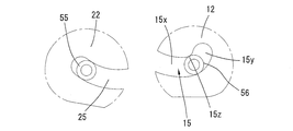
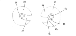
- each of the first guide grooves 15 formed in the pair of side walls 12 of the first hinge main body 10 extends in the direction of approaching and separating from the first shaft member 51. It has a portion 15x (main guide portion) and a sub-groove portion 15y (sub-guide portion) extending upward from one end (end away from the first shaft member 51) of the main groove portion 15x.
- the main groove portion 15x and the sub-groove portion 15y intersect with each other via the bent portion 15z (intersection portion).
- the main groove portion 15x has a downwardly convex curved shape.
- the sub-groove portion 15y extends so as to draw an arc centered on the first shaft member 51.
- the second guide groove 25 extends in a direction of approaching / separating from the second shaft member 52 over the entire length. In the present embodiment, the second guide groove 25 has a curved shape so as to be convex downward when the lid 3 is in the closed position.
- the hinge device 5 further includes four friction plates 60 (friction members) made of stainless steel or the like and two disc springs 61.
- the friction plate 60 and the disc spring 61 constitute a friction resistance generating mechanism.
- the friction plate 60 and the disc spring 61 are penetrated and supported by the intermediate shaft member 50.
- the disc spring 61 is interposed between the flange portion 50a on one end side of the intermediate shaft member 50 and the second arm 40, and the three friction plates 60 are the first arm 30. It is interposed between the second arm 40 and one friction plate 60, and is interposed between the other end of the intermediate shaft member 50 and the first arm 30.
- the first and second arms 30 and 40 and the friction plate 60 come into contact with each other with the pressing force of the disc spring 61, which causes friction between the first and second arms 30 and 40.
- the friction torque that opposes the relative rotation of the second hinge body 20 with respect to the first hinge body 10 is generated, so that the lid 3 is stably maintained at an arbitrary opening angle.
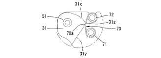
- the hinge device 5 further includes a leaf spring 70 (spring, urging member) provided on the first hinge main body 10. Both ends of the leaf spring 70 have an arc shape, and are hung on two support pins 71 and 72 supported by a pair of side walls 12 of the first hinge main body 10. Both ends of one support pin 71 are inserted and supported in support holes 12a formed in a pair of side walls 12, and both ends of the other support pin 72 are inserted and supported in recesses 12b formed on the edge of the side wall 12. Has been done.
- a leaf spring 70 spring, urging member
- the leaf spring 70 has an obtuse angle and a bent shape, and its central portion is a pressing portion 70a.
- the pressing portion 70a projects toward the tip of the short portion 31 of the first arm 30.
- a first receiving surface 31x and a second receiving surface 31y for receiving the pressing portion 70a of the leaf spring 70 are formed, and the intermediate receiving surface 31z is curved.
- the operation of the hinge device 5 having the above configuration will be described by taking as an example the process in which the lid 3 rotates from the fully open position to the closed position.
- the lid 3 When the lid 3 is in the fully open position at the opening angle of 135 ° shown in FIG. 1, as shown in FIG. 5, the long portion 32 of the first arm 30 hits the second shaft member 52, and the long portion of the second arm 40.
- the 42 hits the first shaft member 51, further rotation of the lid 3 in the opening direction is prohibited.
- the slide pin 55 of the first arm 30 is located near the end of the second guide groove 25 (the end closer to the second shaft member 52), and the slide pin 56 of the second arm 40 is the first guide. It is located near the end of the main groove portion 15x of the groove 15 (the end closer to the first shaft member 51).
- the leaf spring 70 is separated from the short portion 31 of the first arm 30.
- the first and second arms 30 and 40 rotate relative to the first and second hinge main bodies 10 and 20.
- the first and second arms 30 and 40 rotate relative to each other.
- the slide pin 55 slides along the second guide groove 25 and the slide pin 56 slides along the main groove portion 15x of the first guide groove 15, the first and second arms 30, 40 and the first 2
- the locus of relative rotation of the hinge body 20 with respect to the first hinge body 10 is uniquely determined, and the lid 3 can be opened stably.
- the friction by the friction plate 60 causes friction torque with respect to the second hinge main body 20 and the lid 3, so that the lid 3 has a rotational torque that exceeds the friction torque.
- the lid 3 is stably held at an arbitrary angular position in the opening angle range of 135 ° to 40 ° unless the lid 3 is externally applied.
- the pressing portion 70a of the leaf spring 70 comes into contact with the first receiving surface 31x of the short portion 31 of the first arm 30.
- the slide pin 56 of the second arm 40 is located in the main groove portion 15x of the first guide groove 15.
- the pressing portion 70a of the leaf spring 70 presses the first receiving surface 31x at the end of the short portion 31 of the first arm 30.
- a rotational torque in the clockwise direction in the drawing acts on the first arm 30, and a rotational torque in the opening direction acts on the second hinge main body 40 and the lid 3.
- the rotational torque in the opening direction is smaller than the friction torque due to the friction plate 60, so that the closing operation is not a large burden.
- the lid 3 can stably maintain an arbitrary angular position even in an angle range of an opening angle of 40 ° to 20 °.
- the pressing portion 70a of the leaf spring 70 is the second receiving surface of the short portion 31 of the first arm 30.
- a rotational torque in the counterclockwise direction in the drawing is applied to the first arm 30, and a rotational torque in the closing direction is applied to the second hinge main body 20 and the lid 3.
- the direction of the rotational torque by the leaf spring 70 changes, so that the operator can feel a click feeling.
- the rotational torque in the closing direction by the leaf spring 70 is smaller than the friction torque by the friction plate 60, so that the lid 3 stably maintains an arbitrary opening angle even in an angle range of 20 ° to 10 °. be able to.
- the lid 3 reaches the opening angle of 10 °, as shown in FIG. 8B, the slide pin 56 of the second arm 40 approaches the bent portion 15z of the first guide groove 15, but does not reach the auxiliary groove portion 15y. ..
- the slide pin 56 may move along a trajectory drawing an arc centered on the first shaft member 51. it can. Therefore, the assembly including the lid 3, the second hinge main body 20, and the first and second arms 30, 40 is integrally rotated around the first shaft member 51 without being accompanied by relative rotation with each other. To do. In this process, the frictional resistance between the slide pin 56 and the first guide groove 15 becomes substantially zero.
- the pressing portion 70a of the leaf spring 70 presses the second receiving surface 31y of the short portion 31 of the first arm 30, so that the first arm 30 is reached. The state in which the rotation torque is applied in the counterclockwise direction is maintained, and the rotation torque causes the second hinge body 20 and the lid 3 to automatically rotate to the closed position.
- the second hinge main body 20 can rotate relative to the first hinge main body 10 until the slide pin 56 further reaches the end of the sub-groove portion 15y. ..
- the angular position when the slide pin 56 reaches the end of the auxiliary groove portion 15y is defined as the rotation limit position of the hinge device 5.
- ⁇ ° for example, ⁇ 2 °
- the angle range (specific angle range) in which the frictional resistance becomes substantially zero is compared with ⁇ ° to 1 °. Since the angle range (torque application angle range) on which the rotation torque of the leaf spring 70 acts is as wide as ⁇ ° to 20 °, the second hinge body 30 is surely set to the rotation limit position over the entire range of the specific angle range. It can rotate automatically toward.
- a leaf spring 70 having an arc shape at both ends and a protruding center is formed, so that a simple structure can be obtained. Further, even if a plurality of the first arms 30 are made of thin plates, the leaf springs 70 can reliably apply rotational torque to the plurality of first arms 30.
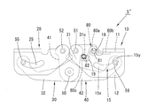
- the second embodiment of the present invention will be described with reference to FIGS. 11 and 12. Since the basic configuration of the hinge device 5'of the present embodiment is the same as that of the first embodiment, the same number will be assigned to each component and duplicate description will be omitted. Further, the reference numerals of the first embodiment are used for the description of the components not shown in FIGS. 11 and 12.
- the catch function is exhibited when the lid 3 is in a closed position with an opening angle of 0 ° and a fully open position with an opening angle of 90 °. The details will be described below.
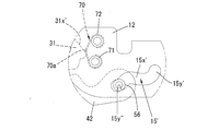
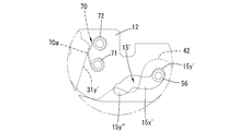
- the first guide groove 15' has a main groove portion 15x'(main guide portion) and a sub-groove portion 15y' (sub-guide portion) connected to one end (the end far from the first shaft member 51) of the main groove portion 15x'. It has another sub-groove portion 15y ”(other sub-guide portion) connected to the other end (end near the first shaft member 51) of the main groove portion 15x.
- the main groove portion 15x' is the first. It extends in the direction of approaching and separating from the shaft member 51.
- the sub-groove portions 15y'and 15y "extend in the direction intersecting the main groove portion 15x'.
- the sub-groove portions 15y'and 15y' extend from the intersection with the main groove portion 15x' so as to draw an arc centered on the first shaft portion 51.
- the tip of the short portion 31 of the first arm 30 has a first receiving surface 31x'and a second receiving surface 31y' away from the first receiving surface 31x'in the circumferential direction.
- the opening angle of the lid 3 exceeds 70 °
- the pressing portion 70a of the leaf spring 70 pushes the first receiving surface 31x', so that a clockwise rotational torque is applied to the first arm 30, which in turn gives a clockwise rotation torque.
- a rotational torque in the opening direction is applied to the lid 3.
- the opening angle of the lid 3 exceeds 80 °
- the slide pin 56 enters the sub-groove portion 15y ”, so that the frictional resistance becomes substantially zero.
- the lid 3 automatically opens in the opening direction. It is rotated and held at an opening angle of 90 ° (fully open position) in a state where rotational torque is applied.
- the opening angle of the lid 3 When the opening angle of the lid 3 is less than 20 °, the pressing portion 70a of the leaf spring 70 pushes the second receiving surface 31y', so that a rotating torque in the counterclockwise direction is applied to the first arm 30, and thus the lid. A rotational torque in the closing direction is applied to 3.
- the opening angle of the lid 3 is less than 10 °, the slide pin 56 enters the sub-groove portion 15y', so that the frictional resistance becomes substantially zero. As a result, the lid 3 is automatically rotated in the closing direction and is held at a closing angle of 0 ° (closed position) in a state where the rotating torque is applied.
- FIGS. 13 to 15 Since the basic configuration of the hinge device 5 ”of the present embodiment is the same as that of the first embodiment, the components will be assigned the same number and duplicate description will be omitted. Further, FIGS. 13 to 15 will be omitted. Reference numerals of the first embodiment are used for the description of the components not shown in.
- the torsion spring 80 shown in FIG. 15 is used instead of the leaf springs of the first and second embodiments.
- the torsion spring 80 includes two coil portions 80a, a U-shaped locking portion 80b connected to these coil portions 80a, and a bent-shaped pressing portion 80c extending from each of the two coil portions 80a to the opposite side of the locking portion 80b. And, in one piece.
- a pressing pin 82 including a support pin 81 and a stepped pin is used.
- the torsion spring 80 is supported by the first hinge main body 10 via the support pin 81.
- the support pin 81 is inserted into the coil portion 80a of the torsion spring 80, and both ends are supported by support holes 18 formed in the pair of side walls 12 of the first hinge main body 10.
- the locking portion 80b of the torsion spring 80 is locked to the base wall 11 of the first hinge main body 10.
- the peripheral surface of the tip of the short portion 31 of the first arm 30 is a first surface region forming an arc surface and a second surface region whose diameter gradually increases in the clockwise direction in the drawing from the first surface region. Further, it has a third surface region whose diameter sharply decreases in the clockwise direction, and this third surface region is provided as a receiving surface 31s that performs the action described later.
- a long hole 19 is formed in the pair of side walls 12 of the first hinge main body 10 near the tip of the short portion 31 of the first arm 30, and both ends of the pressing pin 82 are long holes in the long hole 19. It is slidably inserted along 19. The pressing pin 82 is always urged toward the tip of the short portion 31 of the first arm 30 by the pressing portion 80c of the torsion spring 80 described above.
- the basic operation of the third embodiment is the same as that of the first embodiment.
- the slide pin 56 is located in the main groove portion 15x of the first guide groove 15.
- the pressing pin 82 is in contact with a first region forming an arc surface in the peripheral surface of the short portion 31 of the first arm 30. Therefore, no rotational torque is applied to the first arm 30.
- the lid 3 is at an opening angle of 150 ° to 20 °, the lid 3 is held at an arbitrary opening angle by the friction torque of the friction plate 60.
- the pressing pin 82 When the lid 3 is at an opening angle of 20 ° to 0 °, the pressing pin 82 is in contact with the receiving surface 31s of the first arm 30, and the pressing force of the torsion spring 30 is applied to the receiving surface 31s via the pressing pin 82. As a result, a rotation torque in the counterclockwise direction is applied to the first arm 30, and a rotation torque in the closing direction is applied to the lid 3.
- the lid 3 when the lid 3 is opened at an opening angle of 1 ° to 0 °, the slide pin 56 enters the sub-groove portion 15y of the first guide groove 15, and the frictional resistance becomes substantially zero, so that the torsion spring Due to the rotation torque of 80, the lid 3 is integrated with the first and second arms 30, 40 and the second hinge main body 20 and automatically rotates in the closing direction.
- the fourth embodiment differs from the third embodiment only in the shape of the first guide groove 100.
- Other components (not shown) are the same as those in the third embodiment, and the reference numerals of the third embodiment are used in the description of these components.
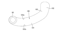
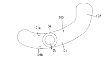
- the first guide groove 100 has a main groove portion 101, a sub groove portion 102, and a bent portion 103 (intersection portion).
- the slide pin 56 is inserted into the main groove portion 101 with a predetermined clearance, for example, a clearance of 50 ⁇ m to 100 ⁇ m. This point is similar to the preceding embodiment.
- FIG. 16A when the lid 3 is in the fully open position with an opening angle of 150 °, the slide pin 56 is located at the end of the main groove portion 101 (the end close to the first shaft member 51).
- FIG. 16B shows the position of the slide pin 56 while the lid 3 is being rotated in the closing direction, for example, when the opening angle of the lid 3 is 60 °.
- the slide pin 56 when the lid 3 is rotating in the closing direction, the slide pin 56 moves so as to be in contact with the upper edge 101a of the main groove portion 101, and the lower edge 101b of the main groove portion 101 and the slide pin The clearance Cb appears between the 56 and the 56.
- the rotation torque by the torsion spring 80 is applied to the lid 3 when the lid 3 opens below an opening angle of 20 ° as in the third embodiment.
- the lid 3 reaches an opening angle of less than 2 °, for example 0.86 °
- the slide pin 56 reaches the sub-groove portion 102 of the first guide groove 100, as shown in FIG. 17A. ..
- the lid 3 is maintained at an arbitrary angle by the same principle as in the above-described embodiment.
- the inner point Pa in the bent portion 103 (the side closer to the first shaft member 51) is the intersection of the upper edge 101a of the main groove portion 101 and the inner edge 102a of the sub-groove portion 102.
- the outer point Pb in the bent portion 103 (the side far from the first shaft portion 51) is the intersection of the lower edge 101b of the main groove portion 101 and the outer edge 102b of the sub-groove portion 102.
- the outer edge 102b of the sub-groove portion 102 is formed on an arc centered on the first shaft member 51 from the point Pb on the outer side of the bent portion 103.
- the inner edge 102a of the sub-groove portion 102 is deviated from the point Pa inside the bent portion 103 so as to approach the first shaft member 51 from the virtual line L that draws an arc centered on the first shaft member 51.
- the separation distance between the inner edge 102a and the virtual line L gradually increases as it approaches the inner end of the sub-groove portion 102.
- the inner edge 102a draws a curve near the point Pa, but draws a straight line behind it.
- the slide pin 56 does not touch any of the edges 102a and 102b of the sub-groove portion 102, so that the frictional resistance due to such contact can be reliably eliminated. .. As a result, even if the force of the torsion spring 80 is weak, the closed state of the lid 3 can be reliably maintained.
- the second hinge body 20 is further relative to the first hinge body 10 until the slide pin 56 reaches the end of the sub-groove portion 15y. It can be rotated.
- the angle position (rotation limit position) of the second hinge body 20 with respect to the first hinge body 10 at this time is ⁇ ° (for example, -4 °) when converted into the opening angle of the lid 3.
- the slide pin 56 shifts to the sub-groove portion 102 when the lid 3 opens at an opening angle of less than 2 °, but it may shift to the sub-groove portion 102 at a larger angle.
- the first guide groove 100 of the fourth embodiment may be applied to the hinge device of the first and second embodiments.
- the present invention is not restricted to the above implementation, and various modifications can be adopted without departing from the gist thereof.
- the first and second arms may be one each.
- the main groove portion of the first guide groove and the second guide groove may extend linearly.
- the first shaft member may be on an extension line of the main groove portion of the first guide groove, or may be detached.
- the urging member for urging the first arm may have a form other than a leaf spring or a torsion spring.
- the first hinge body is fixed to the case body and the second hinge body is fixed to the lid.
- the second hinge body is fixed to the case body and the first hinge body is fixed to the lid. It may be fixed.
- the hinge device of the present invention may be attached to a small device such as a folding door or a personal computer.
- the shape of the sub-groove portion of the first guide groove is not limited to the arc shape centered on the first shaft member, and any shape that allows the other end of the second arm to make an arc movement around the first shaft member. including.
- the frictional resistance generating mechanism can adopt any configuration that generates frictional resistance between the first arm and the second arm. For example, instead of using the friction plate and the disc spring, the tip of the intermediate shaft member may be crimped to bring the first and second arms into strong contact with each other.
- the present invention can be applied to a hinge device including the first and second hinge main bodies and the first and second arms connecting these hinge main bodies.
Landscapes
- Engineering & Computer Science (AREA)
- Mechanical Engineering (AREA)
- General Engineering & Computer Science (AREA)
- Pivots And Pivotal Connections (AREA)
- Telephone Set Structure (AREA)
- Closing And Opening Devices For Wings, And Checks For Wings (AREA)
Abstract
Priority Applications (4)
| Application Number | Priority Date | Filing Date | Title |
|---|---|---|---|
| US17/597,329 US11788331B2 (en) | 2019-07-11 | 2020-06-29 | Hinge device |
| JP2020549821A JP7526669B2 (ja) | 2019-07-11 | 2020-06-29 | ヒンジ装置 |
| CN202080049589.8A CN114144563B (zh) | 2019-07-11 | 2020-06-29 | 合叶装置 |
| EP20836835.7A EP3998409A4 (fr) | 2019-07-11 | 2020-06-29 | Dispositif de charnière |
Applications Claiming Priority (2)
| Application Number | Priority Date | Filing Date | Title |
|---|---|---|---|
| JP2019-129404 | 2019-07-11 | ||
| JP2019129404 | 2019-07-11 |
Publications (1)
| Publication Number | Publication Date |
|---|---|
| WO2021006096A1 true WO2021006096A1 (fr) | 2021-01-14 |
Family
ID=74115167
Family Applications (1)
| Application Number | Title | Priority Date | Filing Date |
|---|---|---|---|
| PCT/JP2020/025520 Ceased WO2021006096A1 (fr) | 2019-07-11 | 2020-06-29 | Dispositif de charnière |
Country Status (5)
| Country | Link |
|---|---|
| US (1) | US11788331B2 (fr) |
| EP (1) | EP3998409A4 (fr) |
| JP (1) | JP7526669B2 (fr) |
| CN (1) | CN114144563B (fr) |
| WO (1) | WO2021006096A1 (fr) |
Cited By (4)
| Publication number | Priority date | Publication date | Assignee | Title |
|---|---|---|---|---|
| WO2022228633A1 (fr) * | 2021-04-29 | 2022-11-03 | Vkr Holding A/S | Charnière pour fenêtre de toit et fenêtre de toit dotée d'un ensemble de charnières |
| WO2022228634A1 (fr) * | 2021-04-29 | 2022-11-03 | Vkr Holding A/S | Charnière pour fenêtre de toit et fenêtre de toit comprenant un ensemble de charnières |
| WO2024116760A1 (fr) * | 2022-11-30 | 2024-06-06 | スガツネ工業株式会社 | Dispositif de charnière |
| US12173504B2 (en) | 2021-04-29 | 2024-12-24 | Vkr Holding A/S | Roof window with a set of hinges |
Families Citing this family (7)
| Publication number | Priority date | Publication date | Assignee | Title |
|---|---|---|---|---|
| CN213309440U (zh) * | 2020-07-09 | 2021-06-01 | 深圳翼诚科技有限公司 | 一种折叠式马桶垫脚凳 |
| CA3199363A1 (fr) * | 2020-11-20 | 2022-05-27 | Giulio ANSELMI | Dispositif de fermeture et/ou d'ouverture d'un battant |
| US12219723B2 (en) * | 2022-06-14 | 2025-02-04 | Microsoft Technology Licensing, Llc | Hinged device having slot defined hinge trajectories |
| CN116556793B (zh) * | 2023-05-10 | 2025-10-10 | 健帆生物科技集团股份有限公司 | 铰接结构及血液净化设备 |
| KR20250078018A (ko) * | 2023-11-24 | 2025-06-02 | 현대자동차주식회사 | 차량의 도어힌지 장치 |
| FR3157285A1 (fr) * | 2023-12-21 | 2025-06-27 | Akwel Vigo Spain Sl | Module de trappe d’accès à une interface d’alimentation ou de chargement d’un véhicule automobile. |
| CN119042218A (zh) * | 2024-08-30 | 2024-11-29 | 维沃移动通信有限公司 | 铰链组件和电子设备 |
Citations (6)
| Publication number | Priority date | Publication date | Assignee | Title |
|---|---|---|---|---|
| JPH056040A (ja) * | 1991-06-27 | 1993-01-14 | Canon Inc | 画像形成装置 |
| JPH0552181U (ja) * | 1991-12-16 | 1993-07-09 | 榎本金属株式会社 | 折り戸 |
| JP2007211577A (ja) * | 2006-01-16 | 2007-08-23 | Hitoshi Nishitani | 隠し丁番 |
| EP2781676A1 (fr) * | 2013-03-22 | 2014-09-24 | OTLAV SpA | Charnière masquée avec dispositif automatique de rappel à une position de fermeture |
| JP2015194242A (ja) * | 2014-03-28 | 2015-11-05 | スガツネ工業株式会社 | ヒンジ |
| US10100970B1 (en) * | 2017-08-10 | 2018-10-16 | Acer Incorporated | Electronic device and hinge structure |
Family Cites Families (25)
| Publication number | Priority date | Publication date | Assignee | Title |
|---|---|---|---|---|
| US2320772A (en) * | 1943-06-01 | Hinge | ||
| US2608713A (en) * | 1949-07-30 | 1952-09-02 | Soss Mfg Company | Friction-catch hinge |
| CH453946A (de) | 1964-03-25 | 1968-03-31 | Bierlich J H | Versteckt angeordnetes Schwingscharnier für kippbare Fenster oder Türen |
| GB1422733A (en) * | 1972-04-21 | 1976-01-28 | Lautenschlager Kg Modellbeschl | Spring closure hinge |
| US4083082A (en) * | 1976-11-10 | 1978-04-11 | Jaybee Manufacturing Corporation | Concealed self-closing hinge for panel door cabinet structure |
| US4827569A (en) * | 1986-08-01 | 1989-05-09 | Mertes Paul M | Flush mounted, fully concealed cabinet hinges |
| US4843680A (en) * | 1988-10-28 | 1989-07-04 | Amerock Corporation | Hinge particularly adapted for use with a false cabinet front |
| CN2155420Y (zh) * | 1993-04-28 | 1994-02-09 | 罗日兴 | 摩擦制动活叶 |
| JP2568275Y2 (ja) | 1993-07-13 | 1998-04-08 | スガツネ工業株式会社 | フラップ扉の扉水平保持装置 |
| EP1577474A3 (fr) * | 2004-03-19 | 2010-07-07 | Dr. Hahn GmbH & Co. KG | Charnière pour arrangement caché entre battant et cadre |
| DE102005039509B3 (de) * | 2005-08-20 | 2006-06-22 | Simonswerk, Gmbh | Türband für eine verdeckte Anordnung zwischen Türzarge und Türflügel |
| US20080289146A1 (en) * | 2007-05-22 | 2008-11-27 | Shun-Tzu Chen | Hidden type of hinge structure |
| JP5358042B2 (ja) * | 2008-04-21 | 2013-12-04 | 均 西谷 | 隠し丁番 |
| WO2010143405A1 (fr) * | 2009-06-08 | 2010-12-16 | スガツネ工業株式会社 | Dispositif d'articulation à deux axes |
| EP2460964A1 (fr) * | 2009-07-30 | 2012-06-06 | Sugatsune Kogyo CO., LTD. | Ensemble charnière biaxial |
| US8982542B2 (en) * | 2010-11-17 | 2015-03-17 | Microsoft Technology Licensing, Llc | Hinge mechanism for mobile electronic device |
| DE102011000150B3 (de) * | 2011-01-14 | 2011-10-06 | Simonswerk, Gesellschaft mit beschränkter Haftung | Türband für eine verdeckte Anordnung zwischen Türrahmen und Türflügel |
| ES2606008T3 (es) * | 2011-09-16 | 2017-03-17 | Koblenz S.P.A. | Una bisagra completamente oculta con dispositivo de cierre integrado para puertas y/o puertas de muebles |
| ITUD20110160A1 (it) * | 2011-10-12 | 2013-04-13 | Otlav Spa | Cerniera a scomparsa per serramenti o mobili |
| DE102013108083B3 (de) * | 2013-07-29 | 2014-05-15 | Simonswerk, Gesellschaft mit beschränkter Haftung | Verdeckt liegendes Türband mit elektrischer Verbindung |
| US9725939B2 (en) * | 2014-03-28 | 2017-08-08 | Hurco Companies, Inc. | Rotatable hinge |
| ITUB20156253A1 (it) * | 2015-12-04 | 2017-06-04 | Dierre Spa | Cerniera a scomparsa |
| JP6566267B2 (ja) * | 2016-12-29 | 2019-08-28 | 西谷 均 | 内蔵型多軸丁番 |
| US10152095B2 (en) * | 2017-02-08 | 2018-12-11 | Compal Electronics, Inc. | Electronic device and hinge assembly thereof |
| CN206647416U (zh) * | 2017-04-01 | 2017-11-17 | 兆利科技工业股份有限公司 | 隐藏式对开铰链 |
-
2020
- 2020-06-29 WO PCT/JP2020/025520 patent/WO2021006096A1/fr not_active Ceased
- 2020-06-29 CN CN202080049589.8A patent/CN114144563B/zh active Active
- 2020-06-29 EP EP20836835.7A patent/EP3998409A4/fr not_active Withdrawn
- 2020-06-29 JP JP2020549821A patent/JP7526669B2/ja active Active
- 2020-06-29 US US17/597,329 patent/US11788331B2/en active Active
Patent Citations (7)
| Publication number | Priority date | Publication date | Assignee | Title |
|---|---|---|---|---|
| JPH056040A (ja) * | 1991-06-27 | 1993-01-14 | Canon Inc | 画像形成装置 |
| JPH0552181U (ja) * | 1991-12-16 | 1993-07-09 | 榎本金属株式会社 | 折り戸 |
| JP2007211577A (ja) * | 2006-01-16 | 2007-08-23 | Hitoshi Nishitani | 隠し丁番 |
| EP2781676A1 (fr) * | 2013-03-22 | 2014-09-24 | OTLAV SpA | Charnière masquée avec dispositif automatique de rappel à une position de fermeture |
| JP2015194242A (ja) * | 2014-03-28 | 2015-11-05 | スガツネ工業株式会社 | ヒンジ |
| JP6092171B2 (ja) | 2014-03-28 | 2017-03-08 | スガツネ工業株式会社 | ヒンジ |
| US10100970B1 (en) * | 2017-08-10 | 2018-10-16 | Acer Incorporated | Electronic device and hinge structure |
Cited By (5)
| Publication number | Priority date | Publication date | Assignee | Title |
|---|---|---|---|---|
| WO2022228633A1 (fr) * | 2021-04-29 | 2022-11-03 | Vkr Holding A/S | Charnière pour fenêtre de toit et fenêtre de toit dotée d'un ensemble de charnières |
| WO2022228634A1 (fr) * | 2021-04-29 | 2022-11-03 | Vkr Holding A/S | Charnière pour fenêtre de toit et fenêtre de toit comprenant un ensemble de charnières |
| EP4365396A3 (fr) * | 2021-04-29 | 2024-07-31 | VKR Holding A/S | Charnière pour fenêtre de toit et fenêtre de toit dotée d'un ensemble de charnières |
| US12173504B2 (en) | 2021-04-29 | 2024-12-24 | Vkr Holding A/S | Roof window with a set of hinges |
| WO2024116760A1 (fr) * | 2022-11-30 | 2024-06-06 | スガツネ工業株式会社 | Dispositif de charnière |
Also Published As
| Publication number | Publication date |
|---|---|
| JP7526669B2 (ja) | 2024-08-01 |
| US11788331B2 (en) | 2023-10-17 |
| JPWO2021006096A1 (fr) | 2021-01-14 |
| EP3998409A4 (fr) | 2023-07-12 |
| CN114144563B (zh) | 2023-09-05 |
| EP3998409A1 (fr) | 2022-05-18 |
| US20220316248A1 (en) | 2022-10-06 |
| CN114144563A (zh) | 2022-03-04 |
Similar Documents
| Publication | Publication Date | Title |
|---|---|---|
| WO2021006096A1 (fr) | Dispositif de charnière | |
| JPH08109940A (ja) | 回転ダンパおよび該ダンパを用いた蓋等の開閉装置 | |
| TW201008714A (en) | Crimping tool | |
| JP3039418B2 (ja) | リングとじ具 | |
| US7823747B2 (en) | Casing with flip cover | |
| JP2007086756A (ja) | ヒンジ装置 | |
| JPWO2016136449A1 (ja) | 扉開閉装置 | |
| JP7001301B1 (ja) | 綴じ具 | |
| JP6823281B2 (ja) | リングとじ具及びリングファイル | |
| CN106460435A (zh) | 用于家具或家用电器的铰链 | |
| US1076568A (en) | Spring-hinge. | |
| JP5598776B2 (ja) | ヒンジ装置 | |
| US7984823B2 (en) | Apparatus for positioning flipping cover relative to base and casing utilizing the same | |
| JP3955868B2 (ja) | 書類等の綴じ具 | |
| TWM581358U (zh) | A multi-axis hinge that can generate multiple stages of switching rotation | |
| CN115602467B (zh) | 按键结构 | |
| WO2024116760A1 (fr) | Dispositif de charnière | |
| KR102696562B1 (ko) | 정확한 위치 멈춤 기능을 가지는 마찰힌지 | |
| KR20260003906A (ko) | 슬라이딩 도어용 신칭 래치 | |
| TW201042172A (en) | Hinge device | |
| JP4355553B2 (ja) | 入力キースイッチ | |
| KR102783066B1 (ko) | 이지 오픈 기어 장치 | |
| JP2024121833A (ja) | ヒンジ | |
| JP7343259B2 (ja) | フックラッチ外れ止め機構およびフック | |
| JP5886942B2 (ja) | 開扉保持装置及びそれを備えたドアヒンジ装置 |
Legal Events
| Date | Code | Title | Description |
|---|---|---|---|
| ENP | Entry into the national phase |
Ref document number: 2020549821 Country of ref document: JP Kind code of ref document: A |
|
| 121 | Ep: the epo has been informed by wipo that ep was designated in this application |
Ref document number: 20836835 Country of ref document: EP Kind code of ref document: A1 |
|
| ENP | Entry into the national phase |
Ref document number: 2020836835 Country of ref document: EP Effective date: 20220211 |
|
| WWW | Wipo information: withdrawn in national office |
Ref document number: 2020836835 Country of ref document: EP |