WO2021006201A1 - Système d'affichage médical, dispositif de commande et procédé de commande - Google Patents
Système d'affichage médical, dispositif de commande et procédé de commande Download PDFInfo
- Publication number
- WO2021006201A1 WO2021006201A1 PCT/JP2020/026167 JP2020026167W WO2021006201A1 WO 2021006201 A1 WO2021006201 A1 WO 2021006201A1 JP 2020026167 W JP2020026167 W JP 2020026167W WO 2021006201 A1 WO2021006201 A1 WO 2021006201A1
- Authority
- WO
- WIPO (PCT)
- Prior art keywords
- image
- display
- area
- information
- surgical field
- Prior art date
- Legal status (The legal status is an assumption and is not a legal conclusion. Google has not performed a legal analysis and makes no representation as to the accuracy of the status listed.)
- Ceased
Links
Images

















Classifications
-
- A—HUMAN NECESSITIES
- A61—MEDICAL OR VETERINARY SCIENCE; HYGIENE
- A61B—DIAGNOSIS; SURGERY; IDENTIFICATION
- A61B90/00—Instruments, implements or accessories specially adapted for surgery or diagnosis and not covered by any of the groups A61B1/00 - A61B50/00, e.g. for luxation treatment or for protecting wound edges
- A61B90/20—Surgical microscopes characterised by non-optical aspects
-
- A—HUMAN NECESSITIES
- A61—MEDICAL OR VETERINARY SCIENCE; HYGIENE
- A61B—DIAGNOSIS; SURGERY; IDENTIFICATION
- A61B90/00—Instruments, implements or accessories specially adapted for surgery or diagnosis and not covered by any of the groups A61B1/00 - A61B50/00, e.g. for luxation treatment or for protecting wound edges
- A61B90/36—Image-producing devices or illumination devices not otherwise provided for
- A61B90/37—Surgical systems with images on a monitor during operation
-
- A—HUMAN NECESSITIES
- A61—MEDICAL OR VETERINARY SCIENCE; HYGIENE
- A61B—DIAGNOSIS; SURGERY; IDENTIFICATION
- A61B1/00—Instruments for performing medical examinations of the interior of cavities or tubes of the body by visual or photographical inspection, e.g. endoscopes; Illuminating arrangements therefor
- A61B1/04—Instruments for performing medical examinations of the interior of cavities or tubes of the body by visual or photographical inspection, e.g. endoscopes; Illuminating arrangements therefor combined with photographic or television appliances
- A61B1/045—Control thereof
-
- A—HUMAN NECESSITIES
- A61—MEDICAL OR VETERINARY SCIENCE; HYGIENE
- A61B—DIAGNOSIS; SURGERY; IDENTIFICATION
- A61B34/00—Computer-aided surgery; Manipulators or robots specially adapted for use in surgery
- A61B34/25—User interfaces for surgical systems
-
- G—PHYSICS
- G06—COMPUTING OR CALCULATING; COUNTING
- G06F—ELECTRIC DIGITAL DATA PROCESSING
- G06F3/00—Input arrangements for transferring data to be processed into a form capable of being handled by the computer; Output arrangements for transferring data from processing unit to output unit, e.g. interface arrangements
- G06F3/01—Input arrangements or combined input and output arrangements for interaction between user and computer
- G06F3/011—Arrangements for interaction with the human body, e.g. for user immersion in virtual reality
- G06F3/013—Eye tracking input arrangements
-
- G—PHYSICS
- G06—COMPUTING OR CALCULATING; COUNTING
- G06F—ELECTRIC DIGITAL DATA PROCESSING
- G06F3/00—Input arrangements for transferring data to be processed into a form capable of being handled by the computer; Output arrangements for transferring data from processing unit to output unit, e.g. interface arrangements
- G06F3/01—Input arrangements or combined input and output arrangements for interaction between user and computer
- G06F3/048—Interaction techniques based on graphical user interfaces [GUI]
- G06F3/0484—Interaction techniques based on graphical user interfaces [GUI] for the control of specific functions or operations, e.g. selecting or manipulating an object, an image or a displayed text element, setting a parameter value or selecting a range
- G06F3/04842—Selection of displayed objects or displayed text elements
-
- G—PHYSICS
- G06—COMPUTING OR CALCULATING; COUNTING
- G06F—ELECTRIC DIGITAL DATA PROCESSING
- G06F3/00—Input arrangements for transferring data to be processed into a form capable of being handled by the computer; Output arrangements for transferring data from processing unit to output unit, e.g. interface arrangements
- G06F3/01—Input arrangements or combined input and output arrangements for interaction between user and computer
- G06F3/048—Interaction techniques based on graphical user interfaces [GUI]
- G06F3/0484—Interaction techniques based on graphical user interfaces [GUI] for the control of specific functions or operations, e.g. selecting or manipulating an object, an image or a displayed text element, setting a parameter value or selecting a range
- G06F3/04845—Interaction techniques based on graphical user interfaces [GUI] for the control of specific functions or operations, e.g. selecting or manipulating an object, an image or a displayed text element, setting a parameter value or selecting a range for image manipulation, e.g. dragging, rotation, expansion or change of colour
-
- G—PHYSICS
- G06—COMPUTING OR CALCULATING; COUNTING
- G06F—ELECTRIC DIGITAL DATA PROCESSING
- G06F3/00—Input arrangements for transferring data to be processed into a form capable of being handled by the computer; Output arrangements for transferring data from processing unit to output unit, e.g. interface arrangements
- G06F3/01—Input arrangements or combined input and output arrangements for interaction between user and computer
- G06F3/048—Interaction techniques based on graphical user interfaces [GUI]
- G06F3/0484—Interaction techniques based on graphical user interfaces [GUI] for the control of specific functions or operations, e.g. selecting or manipulating an object, an image or a displayed text element, setting a parameter value or selecting a range
- G06F3/0485—Scrolling or panning
-
- G—PHYSICS
- G06—COMPUTING OR CALCULATING; COUNTING
- G06F—ELECTRIC DIGITAL DATA PROCESSING
- G06F3/00—Input arrangements for transferring data to be processed into a form capable of being handled by the computer; Output arrangements for transferring data from processing unit to output unit, e.g. interface arrangements
- G06F3/16—Sound input; Sound output
- G06F3/167—Audio in a user interface, e.g. using voice commands for navigating, audio feedback
-
- G—PHYSICS
- G06—COMPUTING OR CALCULATING; COUNTING
- G06T—IMAGE DATA PROCESSING OR GENERATION, IN GENERAL
- G06T3/00—Geometric image transformations in the plane of the image
- G06T3/40—Scaling of whole images or parts thereof, e.g. expanding or contracting
-
- H—ELECTRICITY
- H04—ELECTRIC COMMUNICATION TECHNIQUE
- H04N—PICTORIAL COMMUNICATION, e.g. TELEVISION
- H04N23/00—Cameras or camera modules comprising electronic image sensors; Control thereof
- H04N23/60—Control of cameras or camera modules
-
- H—ELECTRICITY
- H04—ELECTRIC COMMUNICATION TECHNIQUE
- H04N—PICTORIAL COMMUNICATION, e.g. TELEVISION
- H04N7/00—Television systems
- H04N7/18—Closed-circuit television [CCTV] systems, i.e. systems in which the video signal is not broadcast
-
- A—HUMAN NECESSITIES
- A61—MEDICAL OR VETERINARY SCIENCE; HYGIENE
- A61B—DIAGNOSIS; SURGERY; IDENTIFICATION
- A61B17/00—Surgical instruments, devices or methods
- A61B2017/00017—Electrical control of surgical instruments
- A61B2017/00203—Electrical control of surgical instruments with speech control or speech recognition
-
- A—HUMAN NECESSITIES
- A61—MEDICAL OR VETERINARY SCIENCE; HYGIENE
- A61B—DIAGNOSIS; SURGERY; IDENTIFICATION
- A61B34/00—Computer-aided surgery; Manipulators or robots specially adapted for use in surgery
- A61B34/25—User interfaces for surgical systems
- A61B2034/256—User interfaces for surgical systems having a database of accessory information, e.g. including context sensitive help or scientific articles
-
- A—HUMAN NECESSITIES
- A61—MEDICAL OR VETERINARY SCIENCE; HYGIENE
- A61B—DIAGNOSIS; SURGERY; IDENTIFICATION
- A61B90/00—Instruments, implements or accessories specially adapted for surgery or diagnosis and not covered by any of the groups A61B1/00 - A61B50/00, e.g. for luxation treatment or for protecting wound edges
- A61B90/36—Image-producing devices or illumination devices not otherwise provided for
- A61B90/37—Surgical systems with images on a monitor during operation
- A61B2090/378—Surgical systems with images on a monitor during operation using ultrasound
-
- A—HUMAN NECESSITIES
- A61—MEDICAL OR VETERINARY SCIENCE; HYGIENE
- A61B—DIAGNOSIS; SURGERY; IDENTIFICATION
- A61B90/00—Instruments, implements or accessories specially adapted for surgery or diagnosis and not covered by any of the groups A61B1/00 - A61B50/00, e.g. for luxation treatment or for protecting wound edges
- A61B90/20—Surgical microscopes characterised by non-optical aspects
- A61B90/25—Supports therefor
-
- A—HUMAN NECESSITIES
- A61—MEDICAL OR VETERINARY SCIENCE; HYGIENE
- A61B—DIAGNOSIS; SURGERY; IDENTIFICATION
- A61B90/00—Instruments, implements or accessories specially adapted for surgery or diagnosis and not covered by any of the groups A61B1/00 - A61B50/00, e.g. for luxation treatment or for protecting wound edges
- A61B90/36—Image-producing devices or illumination devices not otherwise provided for
- A61B90/361—Image-producing devices, e.g. surgical cameras
-
- G—PHYSICS
- G06—COMPUTING OR CALCULATING; COUNTING
- G06F—ELECTRIC DIGITAL DATA PROCESSING
- G06F2203/00—Indexing scheme relating to G06F3/00 - G06F3/048
- G06F2203/048—Indexing scheme relating to G06F3/048
- G06F2203/04803—Split screen, i.e. subdividing the display area or the window area into separate subareas
-
- G—PHYSICS
- G06—COMPUTING OR CALCULATING; COUNTING
- G06F—ELECTRIC DIGITAL DATA PROCESSING
- G06F2203/00—Indexing scheme relating to G06F3/00 - G06F3/048
- G06F2203/048—Indexing scheme relating to G06F3/048
- G06F2203/04806—Zoom, i.e. interaction techniques or interactors for controlling the zooming operation
Definitions
- the present technology relates to medical display systems, control devices, and control methods, and in particular, medical display systems, control devices, and controls that enable the presentation of necessary information without disturbing the concentration of the operator. Regarding the method.
- the surgeon who performs the surgery while looking at the surgical field image captured by the medical imaging device needs to make a decision about the surgery by looking at the information of other medical devices in addition to the surgical field image.
- Patent Document 1 discloses a technique for aggregating and displaying a surgical field image and information on a plurality of medical devices on one screen.
- This technology was made in view of such a situation, and makes it possible to present necessary information without hindering the concentration of the surgeon.
- the medical display system of one aspect of the present technology is generated by a device including a surgical field image signal generated by a medical imaging device that images the surgical field of a patient and an external device excluding the medical imaging device.
- a control device including an acquisition unit for acquiring a presentation information signal and a control unit for generating a display image based on the surgical field image signal and the presentation information signal is provided, and the control unit displays the display image.
- the presentation information generated from the presentation information signal is arranged in the upper region, and the surgical field generated based on the surgical field image signal is placed in the central region having the same length in the horizontal direction as the upper region.
- An image is arranged, user interface information for controlling the control device is arranged in an area below the upper area, and the display image is generated so as to be displayed.
- the control device on one aspect of the present technology is a surgical field image signal generated by a medical imaging device that images the surgical field of a patient, and presentation information generated by a device including an external device excluding the medical imaging device.
- the control unit includes an acquisition unit that acquires a signal and a control unit that generates a display image based on the surgical field image signal and the presentation information signal, and the control unit is an upper region of the display area of the display image.
- the presentation information generated from the presentation information signal is arranged in the central region having the same length in the horizontal direction as the upper region, and the surgical field image generated based on the surgical field image signal is arranged in the above.
- User interface information for controlling the control device is arranged in an area below the upper area, and the display image is generated so as to be displayed.
- the control device is generated by a device including a surgical field image signal generated by a medical imaging device that images the surgical field of a patient and an external device excluding the medical imaging device.
- the presented information signal was acquired, and a display image was generated based on the surgical field image signal and the presentation information signal, and was generated from the presentation information signal in the upper area of the display area of the display image.
- the presentation information is arranged, and the surgical field image generated based on the surgical field image signal is arranged in the central region having the same length in the horizontal direction as the upper region, and the surgical field image generated based on the surgical field image signal is arranged in the region below the upper region.
- User interface information for controlling the control device is arranged, and the display image is generated so as to be displayed.
- the surgical field image signal generated by the medical imaging device for imaging the surgical field of the patient and the device including the external device excluding the medical imaging device are generated.
- the presentation information signal is acquired, a display image is generated based on the surgical field image signal and the presentation information signal, and the presentation information generated from the presentation information signal is in the upper region of the display area of the display image.
- the surgical field image generated based on the surgical field image signal is placed in the central region having the same length in the horizontal direction as the upper region, and the control is placed in the region below the upper region.
- the display image is generated so that user interface information for controlling the device is arranged and displayed.
- the surgical field image signal generated by the medical imaging device that images the surgical field of the patient and the presentation generated by the device including the external device excluding the medical imaging device.
- An information signal is acquired, a display image is generated based on the surgical field image signal and the presentation information signal, and the presentation information generated from the presentation information signal is generated in the upper area of the display area of the display image.
- the surgical field image generated based on the surgical field image signal is placed in the central region having the same length in the horizontal direction as the upper region, and the control device is placed in the region below the upper region.
- the display image is generated so as to arrange and display the user interface information for controlling.
- FIG. 1 is a diagram showing a state of surgery using a medical display system according to an embodiment of the present technology.
- the medical display system 1 of FIG. 1 is composed of a microscope device 11, a control device 12, a monitoring device 13, and a display device 14.
- the operator 21 is performing an operation on a patient 23 on a patient bed 22 by using a medical display system 1 composed of such devices. ..
- the “user” means an arbitrary medical staff who uses the medical display system 1, such as an operator and an assistant.
- the microscope device 11 is an electron imaging type microscope device (so-called video type microscope device).
- the microscope device 11 images the surgical site of the patient and outputs a signal representing the surgical field image showing the surgical field to the control device 12.
- a medical imaging device such as an endoscope may be used instead of the microscope device 11.
- the control device 12 is a server device, a personal computer, or the like.
- the control device 12 displays a display image based on the signal of the surgical field image supplied from the microscope device 11 (surgical field image signal) and the signal of the presentation information supplied from the device including the external device (presentation information signal). Generate.
- the monitoring device 13 is included in the external device. Therefore, the monitoring information signal (monitoring information signal) supplied from the monitoring device 13 is included in the presentation information signal. A signal representing the monitoring information obtained by monitoring the biological information (biological reaction) of the patient 23 is supplied from the monitoring device 13.
- the control device 12 causes the display device 14 to display a display image including the surgical field image and the presentation information.
- control device 12 may be performed by wired communication or wireless communication.
- the control device 12 and the external server 16 are connected via a predetermined network 15 such as the Internet or a LAN (Local Area Network), for example. It is also possible to superimpose the medical information acquired from the external server 16 on the display image and display it on the display device 14.
- a predetermined network 15 such as the Internet or a LAN (Local Area Network), for example. It is also possible to superimpose the medical information acquired from the external server 16 on the display image and display it on the display device 14.
- the monitoring device 13 monitors the biological information of the patient 23 and generates monitoring information representing the monitoring result of the biological information.
- the biological information of the patient 23 includes an electrocardiogram, a heart rate, a blood oxygen saturation, an arterial pressure, and the like.
- the monitoring device 13 outputs a signal representing monitoring information to the control device 12.
- the display device 14 is provided near the user, such as the wall surface of the operating room.
- the display device 14 displays the display image generated by the control device 12 according to the control by the control device 12.
- the display device 14 displays various information related to the surgery, such as biological information, physical information, and surgical procedure information of the patient 23, as well as the surgical field image captured by the microscope device 11.
- the display of the display device 14 is appropriately switched by an operation by the user.
- various display devices such as a liquid crystal display device or an EL (Electro Luminescence) display device are used.
- a camera that captures the state of the user performing surgery a microphone that detects the voice emitted by the user, various sensors, and the like are installed.
- the line of sight of the user is detected based on the captured image, and the display of the display device 14 is switched. Further, the display of the display device 14 is switched or an operation using the display of the display device 14 is performed based on the user's voice detected by the microphone.
- the external server 16 is, for example, a server device installed in a hospital. Medical information and the like are stored in the external server 16.
- the display image generated by the control device 12 is displayed on the display device 14.
- the user performs various treatments such as excision of the affected part while observing the state of the operated part by looking at the display image displayed on the display device 14.
- FIG. 2 is a diagram showing an example of the area configuration of the display image displayed on the display device 14.
- the presentation information area A1 and the operation menu area A3, which are narrow band-shaped areas, are arranged above and below the surgical field image area A2, which is the area where the surgical field image is displayed. Consists of being done.
- the surgical field image area A2 is defined as an area having a wider width (height) in the vertical direction than the presentation information area A1 and the operation menu area A3.
- the presentation information area A1 is a display area for presentation information including monitoring information representing the monitoring result by the monitoring device 13.
- the presentation information is displayed in a predetermined display form including text, a graph, and the like.
- FIG. 3 is an enlarged view of the presentation information area A1 in which the presentation information including the monitoring information is displayed.
- the electrocardiogram waveform, heart rate, pulse wave, blood oxygen saturation, and arterial pressure are displayed as monitoring information in order from the left.
- information on surgical instruments such as information representing the output of the electric knife used by the user and information on time such as a timer are displayed.
- the presentation information is information generated from the presentation information signal acquired from the device including the external device (monitoring device 13, etc.) excluding the medical imaging device such as the microscope device 11. Therefore, in the presentation information area A1, in addition to the monitoring information, various information that needs to be presented to the user, such as information on surgical instruments and time, is displayed as presentation information.
- the presented information is modality information including monitoring information.
- the presented information may include information on surgical instruments and time.
- monitoring information, surgical instruments and time information can be information that changes in real time.
- the surgical field image area A2 formed in a wide range in the center on the display image is a display area of the surgical field image captured by the microscope device 11.
- the surgical field image displayed in the surgical field image area A2 is an image that changes in real time.
- the operation menu area A3 is a display area of an operation menu (operation panel) composed of various optional items.
- operation menu operation panel
- the user performs various operations such as selecting an image to be displayed on the display device 14 and causing the control device 12 to communicate with the external server 16. It can be carried out. In this way, the user interface information used for the user's operation is displayed in the operation menu area A3.
- FIG. 4 is an enlarged view showing the operation menu area A3 in which the operation menu is displayed.
- each device such as the control device 12 by selecting an option item.
- each option item may be displayed by an icon.
- PB control is an item for displaying the surgical field image immediately after the start of bleeding on the display device 14 in a predetermined area in the display image.
- Zoom is an item for controlling the display magnification of the surgical field image.
- “Move” is an item for displaying information for controlling the display range of the surgical field image on the display device 14.
- “Pivot” is an item for controlling the imaging angle of the microscope device 11 with respect to the surgical site.
- Timer is an item for displaying the timer in the presentation information area A1 on the display device 14. For example, the user can display the elapsed time in the presentation information area A1 together with the preset time.
- Reference is an item for causing the control device 12 to perform reference information presentation processing described later.
- An operation menu consisting of a plurality of optional items as described above is displayed in the operation menu area A3.
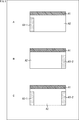
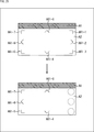
- FIG. 5 is a diagram showing an example of other area configurations of the displayed image.
- a to C in FIG. 5 show display images in which the arrangement positions of the operation menus are different.
- Each of the display images A to C in FIG. 5 is the same as the display image described with reference to FIG. 2, except that the arrangement positions of the operation menus are different. Duplicate explanations will be omitted as appropriate.
- the operation menu area A3-1 which is the display area of the operation menu is arranged as a vertically long area at the left end of the display image.
- a predetermined gap is formed between the presentation information area A1 and the operation menu area A3-1.
- the option items are displayed side by side in the vertical direction. In this case, it is possible to secure a wider vertical width of the surgical field image area A2.
- the operation menu area A3-2 which is the display area of the operation menu, is arranged at the right end symmetrically with the operation menu area A3-1 in the display image of A in FIG.
- the operation menu area A3-1 is arranged at the left end of the display image, and the operation menu area A3-2 is arranged at the right end. In this way, the operation menu may be displayed in the two areas, the left end and the right end.
- FIG. 6 is a diagram showing an example of still another area configuration of the displayed image.
- the presentation information area A1 and the operation menu area A3 may be arranged so as to overlap the surgical field image area A2.
- a predetermined transmittance is set for the display of the presentation information area A1 and the display of the operation menu area A3.
- Presented information in the presentation information area A1 and operation menu When the operation menu in the area A3 is set as the upper layer, a part of the surgical field image in the surgical field image area A2 can be seen through the lower layer.
- the area configuration on the right side of FIG. 6 is the same as the area configuration of the display image described with reference to FIG. That is, the presentation information area A1 is arranged in contact with the upper part of the surgical field image area A2.
- the operation menu area A3 is arranged in contact with the lower part of the surgical field image area A2.
- control device 12 it is possible to display the presented information on one image together with the surgical field image in a form arranged on the surgical field image.
- the surgeon during the operation often looks at his / her hand even if he / she is performing the operation while looking at the display image displayed on the display device, and also to the person next to him (assistant, etc.) or other equipment. It is also expected to divert the line of sight. That is, the operator's line of sight tends to go in the left-right direction and the downward direction. On the other hand, if the surgeon's line of sight goes upward, it is highly possible that he or she is consciously looking at it.
- the presented information is displayed above the surgical field image, the surgeon must consciously look at the presented information in order to see it, so the surgery is performed while looking at the surgical field image. It is possible to present the presented information without disturbing the concentration of the surgeon.
- FIG. 7 is a block diagram showing a hardware configuration example of the control device 12.
- the CPU Central Processing Unit
- the ROM Read Only Memory
- the RAM Random Access Memory
- An input / output interface 55 is further connected to the bus 54.
- An input unit 56, an output unit 57, a recording unit 58, a communication unit 59, and a drive 60 are connected to the input / output interface 55.
- the input unit 56 includes a microphone, a keyboard, a mouse, and the like.
- the output unit 57 includes a speaker, a display, and the like.
- the recording unit 58 includes a hard disk, a non-volatile memory, and the like.
- the communication unit 59 includes a network interface and the like.
- the communication unit 59 communicates with an external device such as the microscope device 11, the monitoring device 13, and the external server 16 connected via the network 15.
- the drive 60 drives a removable recording medium 61 such as a magnetic disk, an optical disk, a magneto-optical disk, or a semiconductor memory.
- a removable recording medium 61 such as a magnetic disk, an optical disk, a magneto-optical disk, or a semiconductor memory.
- the CPU 51 loads the program recorded in the ROM 52 and the recording unit 58 into the RAM 53 via the input / output interface 55 and the bus 54 and executes the program as described above. Screen display is performed.
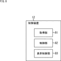
- FIG. 8 is a block diagram showing a functional configuration example of the control device 12. At least a part of the functional units shown in FIG. 8 is realized by executing a predetermined program by the CPU 51 of FIG. 7.
- the acquisition unit 81, the control unit 82, and the display control unit 83 are realized.
- the acquisition unit 81 controls the communication unit 59 of FIG. 7 to acquire the signal of the surgical field image output from the microscope device 11 and the signal of the presentation information output from the external device including the monitoring device 13.
- the signal acquired by the acquisition unit 81 is supplied to the control unit 82.
- the signal of the presented information may be generated in the control device 12 and acquired by the acquisition unit 81.
- the control unit 82 generates presentation information and a surgical field image based on the signal supplied from the acquisition unit 81.
- the control unit 82 generates the display image having the area configuration of FIG. 2 by arranging the presentation information at the upper part of the surgical field image and arranging the operation menu at the lower part of the surgical field image.
- the control unit 82 outputs the display image to the display control unit 83.
- the display control unit 83 outputs the display image supplied from the control unit 82 to the display device 14 to display the display image.
- step S1 the acquisition unit 81 acquires the signal of the surgical field image output from the microscope device 11 and the signal of the presentation information output from the external device or the signal of the presentation information generated by the control device 12. Output to the control unit 82.
- step S2 the control unit 82 generates a display image based on the signal supplied from the acquisition unit 81, and outputs the display image to the display control unit 83.
- step S3 the display control unit 83 outputs the display image to the display device 14 and displays the display image.
- step S4 the control unit 82 determines whether or not to end the process.
- step S4 If it is determined in step S4 that the process is not terminated, the process returns to step S1 and the subsequent processes are performed. That is, the surgical field image and the presentation information that change in real time are updated and reflected in the display image.
- step S4 if it is determined in step S4 that the process is to be terminated, the presentation process is terminated.
- control device 12 can present the presented information including the monitoring information without disturbing the concentration of the user performing the operation while viewing the surgical field image.
- Second Embodiment> the line of sight of the user with respect to the display device 14 is detected.
- the gazing point which is the position on the display image seen by the user, is obtained from the detected line of sight, and the display method of the presentation information area A1 in FIG. 2 is switched based on the obtained gazing point.
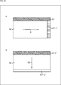
- FIG. 10 is a diagram showing an example of a display method of the presentation information area A1.
- the presentation information area A1-1 and the operation menu area A3, which are display areas for the presentation information, are arranged so as to overlap the surgical field image area A2.
- the control device 12 After the display image is displayed on the display device 14, the control device 12 is required to gaze at the user's display image. In the upper example of FIG. 10, the gazing point P1 on the displayed image is obtained based on the line of sight of the user. When there is no gazing point on the presentation information area A1-1, the control device 12 sets a predetermined transmittance for the display of the presentation information area A1-1.
- the gazing point P2 on the presentation information area A1-2 is required.
- the control device 12 When the gazing point is on the presentation information area A1-2, the control device 12 generates a display image without setting the transmittance for the display of the presentation information area A1-2.
- the control device 12 controls the transmittance of the presentation information area A1 based on the detected line of sight to generate a display image.
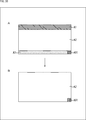
- FIG. 11 shows an example of a display method of the presentation information area A1 in which the presentation information is displayed.
- FIG. 11 shows an example of a steady state which is a display when there is no gazing point on the presentation information area A1-1.
- Presentation information such as monitoring information similar to the presentation information area A1 described with reference to FIG. 3 is displayed in the presentation information area A1-1 with a predetermined transmittance.
- the display of the presented information area A1-1 fits out of the field of view, so that the user can concentrate on the procedure without worrying about the presented information. ..
- the lower part at the tip of the arrow in FIG. 11 shows an example of highlighting which is a display when the gazing point is on the presentation information area A1-2.
- Presentation information such as monitoring information similar to the presentation information area A1 described with reference to FIG. 3 is displayed in the presentation information area A1-2 without setting the transmittance.
- the user can clearly see the highlighted presentation information by looking at the presentation information area A1-2 only when it is necessary to see the presentation information.
- switching between the steady state and highlighting may be performed based on information about the user such as voice, touch operation, and gesture (motion) by the user, not limited to the user's line of sight.
- the steady state and the highlighting may be switched by another setting of the display of the presentation information area A1.
- the steady state and the highlighting may be switched by changing the display brightness of the presentation information area A1, changing the display color, or reversing the display color.
- FIG. 12 is a diagram showing an example of another display method of the presentation information area A1 in which the presentation information is displayed.
- the display image composed of the surgical field image area A2 and the operation menu area A3, which are areas other than the presentation information area A1, is displayed. Is displayed.
- the display of the presentation information area A1 is gradually displayed from the lower part to the upper part with the passage of time. For example, when the user's line of sight is detected above the surgical field image area A2, the presentation information is displayed. Further, when the user's line of sight is directed to a predetermined area, the presented information may be displayed by fading in or the like.
- the highlighting process of FIG. 13 is started after the display image of the steady state is displayed on the display device 14.
- the control unit 82 detects the user's line of sight based on the captured image captured by the camera.
- the control unit 82 obtains the gaze point on the displayed image based on the detected line of sight of the user, and determines whether or not the line of sight for the presentation information area A1 for a predetermined period or longer is detected based on the obtained gaze point. To do.
- step S101 If it is determined in step S101 that the line of sight of the presented information area A1 for a predetermined period or longer is detected, the process proceeds to step S102.
- step S102 the control unit 82 generates a display image by arranging the presentation information so as to be displayed in highlighting, and outputs the display image to the display control unit 83.
- the display control unit 83 outputs the display image supplied from the control unit 82 to the display device 14, and displays the display image.
- step S103 the control unit 82 determines whether or not to end the highlighting process. If it is determined in step S101 that the line of sight to the presentation information area A1 for a predetermined period or longer has not been detected, step S102 is skipped, the process proceeds to step S103, and whether or not to end the highlighting process. Is determined.
- step S103 If it is determined in step S103 that the highlighting process is not terminated, the process returns to step S101, and the subsequent processes are performed.
- step S103 if it is determined in step S103 that the highlighting process is terminated, the highlighting process is terminated.
- the presentation information can be clearly presented only when the user needs the presentation information.
- FIG. 14 is a diagram showing an example of the area configuration of the display image displayed on the display device 14 when “Reference” is selected.
- the display image when "Reference" is selected is a narrow band-shaped area above the surgical field image area A2, which is the area where the surgical field image is displayed.
- the information area A1 is arranged, and the reference information group areas A11 to A14, which are rectangular areas, are arranged so as to be superimposed on the surgical field image area A2.
- Each of the display images of A and B in FIG. 14 is the same as the display image described with reference to FIG. 2 except that the operation menu area A3 does not exist and the reference information group areas A11 to A14 exist. The description to be made will be omitted as appropriate.
- the reference information group areas A11 and A12 are arranged vertically side by side on the left side of the displayed image.
- a predetermined gap is formed between the reference information group areas A11 and A12 and the left end of the displayed image. Further, a predetermined gap is formed between the reference information group area A12 and the lower end of the display image, and also between the reference information group area A11 and the presentation information area A1.
- the reference information group areas A13 and A14 are further arranged on the right side of the display image in symmetry with the reference information group areas A11 and A12.
- the reference information group areas A11 to A14 are display areas for the reference image.
- the reference image includes monitoring information representing the monitoring result by the monitoring device 13 and medical information acquired from the external server 16.
- Medical information includes pathological images, ultrasound images, ICG (Indocyanine green) images, MRI (Magnetic Resonance Imaging) images, CT (Computed Tomography) images, angio images (angiographic images), X-ray images, etc. Is done.
- Reference images are divided into predetermined reference information groups.
- the reference information group areas A11 to A14 information representing the reference information group is displayed for each reference information group.
- the positions of the reference information group areas A11 to A14 on the display image may be determined based on the category of the reference information group.
- the information of each reference information group having the same reference information group category can be displayed side by side on the same side of the left and right sides of the display image.
- reference images such as monitoring information and ultrasonic images that are updated in real time are displayed in the reference information group areas A11 and A12, and before the start of surgery such as MRI images and CT images in the reference information group areas A13 and A14.
- the reference image prepared in is displayed.
- the reference information group areas A11 to A14 may be arranged vertically side by side on the left side of the displayed image. Further, the reference information group areas A11 to A14 may be arranged on the right side of the display image symmetrically with the reference information group areas A11 to A14 in the display image of FIG. 14B.
- FIG. 15 is a diagram showing an example of a display image in which information representing a reference information group is displayed.
- thumbnail images corresponding to the reference information group are displayed in the reference information group areas A11 to A14 as information representing the reference information group.
- the reference image is classified into four groups as a reference information group: monitoring information, ultrasonic image, ICG image, and MRI image.
- a reference information group displayed in the reference information group areas A11 to A14
- images representing monitoring information, ultrasonic images, ICG images, and MRI images are used, respectively.
- Any group may be set as the reference information group, and any image may be used as the thumbnail image.
- a surgical navigation image showing the surgical navigation may be set as a reference information group, and the surgical navigation image may be displayed in the reference information group area.
- the thumbnail image one may be selected from the reference images associated with each group and used as the thumbnail image.
- FIG. 16 is an enlarged view of the reference information group area A11 in which the thumbnail image of the monitoring information is displayed and the reference information group area A12 in which the thumbnail image of the ultrasonic image is displayed.
- the monitoring information representing the monitoring result by the monitoring device 13 is displayed vertically arranged in the reference information group area A11 as a thumbnail image representing the monitoring information.
- the monitoring information displayed in the reference information group area A11 may be information including the monitoring information displayed in the presentation information area A1 described with reference to FIG.
- the name of the displayed reference information group and the number or symbol representing the reference information group are displayed.
- the text “Monitor” is displayed above the reference information group area A11 as the name of the monitoring information which is the reference information group.
- the text of "L1" is displayed as a symbol representing monitoring information.
- the ultrasonic image acquired from the external server 16 is displayed in the reference information group area A12 as a thumbnail image representing the ultrasonic image.
- the text "Ultrasound” is displayed as the name of the ultrasonic image which is the reference information group, as in the reference information group area A11. Further, on the right side of the text of "Ultrasound", the text of "L2" is displayed as a symbol representing the ultrasonic image.
- the user can display the reference images included in the selected reference information group in a list by selecting the displayed thumbnail image. At this time, the user can select the thumbnail image of the reference information group by, for example, the line of sight or the voice.
- the user can select a thumbnail image of the reference information group by issuing a name of the reference information group or a symbol representing the reference information group as voice. Further, when the line-of-sight input is performed, the user can surely select the necessary reference information group by looking at the name of the reference information group.
- FIG. 17 is a diagram showing an example of a display image in which reference images are displayed in a list.
- the display image in the upper part of FIG. 17 is the same display image as the display image in which the thumbnail image of the reference information group described with reference to FIG. 15 is displayed.
- the dashed rectangle R1 diagonally to the lower right of the displayed image indicates that the thumbnail image of the MRI image displayed in the reference information group area A14 has been selected.
- the control device 12 When an MRI image is selected, the control device 12 generates, for example, the display image shown in the lower part of FIG. In the example of the display image in the lower part of FIG. 17, the presentation information area A1 is arranged on the surgical field image area A2, and the rectangular reference image areas A31-1 to A31-7 are superimposed on the surgical field image area A2.
- the display image is configured by arranging the images.
- the reference image areas A31-1 to A31-7 move from the right side to the left side in that order. It is arranged so as to move, and is arranged horizontally side by side under the displayed image.
- Reference image areas A31-1 to A31-7 are display areas for reference images included in the reference information group selected by the user.
- reference images which are different MRI images, are displayed in the reference image areas A31-1 to A31-7.
- the reference image area is seven areas, but the number of reference image areas constituting the display image is arbitrary.
- the control device 12 switches the reference image to be displayed in the reference image area by accepting a predetermined operation by the user.
- information regarding the number of reference images included in the selected reference information group is displayed in the operation menu.
- operation items such as "Go Back” for returning to the reference information group selection screen and "Cancel” for canceling the selection of the reference image and canceling the display of the reference image may be displayed in the operation menu.
- the display image including the reference image area is not generated, and the display image in which the reference image is displayed in the selection reference image area described later is generated. Will be done.
- the user can display only the selected reference image among the reference images included in the reference information group by selecting the reference image to be displayed. At this time, the user can select the reference image by, for example, the line of sight or the voice.
- the user can select a reference image by issuing a number or a symbol representing each reference image as voice.
- the broken line rectangle R2 shown below the display image in the lower part of FIG. 17 indicates that the reference image displayed in the reference image area A31-3 has been selected by the user.
- FIG. 18 is a diagram showing an example of a display image in which the selected reference image is displayed.
- the upper display image of FIG. 18 is a display image displayed after the display image displayed in the reference image area A31-3 of FIG. 17 is selected.
- the rectangular selection reference image area A41 is superimposed and arranged on the display image described with reference to FIG.
- the selection reference image area A41 is arranged at the right end of the display image.
- a predetermined gap is formed between the selection reference image area A41 and the presentation information area A1, the selection reference image area A41 and the operation menu area A3.
- the selected reference image area A41 is a display area of the reference image selected by the user from the list of reference images included in the reference information group.
- the MRI image selected by the user is displayed in the selection reference image area A41.
- the surgical field image area A2 may be arranged so as to be shifted in the direction opposite to the selection reference image area A41.
- the displayed image is displayed in FIG. 2 as shown in the lower part of FIG.
- the rectangular selection reference image areas A41 and A42 may be superimposed and arranged on the display image described with reference to the above.
- the selection reference image areas A41 and A42 are arranged vertically side by side at the right end of the display image.
- the selected reference image area A42 is a display area of a reference image selected by the user from the list of reference images included in the reference information group, similarly to the selected reference image area A41.
- the ICG image is displayed in the selection reference image area A42.
- the control device 12 when "Reference" is selected again after the display of the reference image is erased by the user's selection of the "Cancel” item or the like, the control device 12 was selected at the time of the previous selection of "Reference".
- the reference image may be displayed again as a reference image or presented to the user as a candidate image.
- the candidate image is an image to which a visual effect different from other images is added in the list of reference images so that it can be seen that the reference image was selected last time.
- FIG. 19 is a diagram showing an example in which a display image in which two reference images selected by the user are displayed is enlarged.
- the display image of FIG. 19 is the same as the display image shown and described in the lower part of FIG. 18, except that the text is superimposed on the surgical field image, and therefore the overlapping description will be omitted as appropriate. ..
- numbers and names representing the reference images displayed in the selected reference image areas A41 and A42 are displayed.
- the user can select a reference image displayed by the line of sight and enlarge and display the selected reference image on the display image. Further, the user may select the displayed reference image by issuing a number or a name representing the reference image as voice.
- the operation indicator area A51 may be arranged so as to be superimposed on the surgical field image area A2.
- the operation indicator region A51 is arranged above the surgical field image region A2.
- the position on the display image on which the operation indicator area A51 is arranged may be determined by the control device 12 based on the line of sight of the user detected by the control device 12.
- the operation indicator area A51 includes a display area of a number and a name representing the surgical field image displayed in the surgical field image area A2.
- the text "CAMERA" as a name representing the surgical field image is displayed in the operation indicator area A51 together with the number representing the surgical field image.
- the user By directing the line of sight to the operation indicator area A51, the user selects the surgical field image and is in the initial state, that is, the presentation information area A1, the surgical field image area A2, and the operation menu area described with reference to FIG. A display image composed of A3 can be displayed. Further, the user may select the surgical field image by issuing a number or a name representing the surgical field image as a voice.
- the presented information and the surgical field image are displayed on one image in the form of arranging the presented information on the surgical field image, and an external server outside the operating room.
- the reference images obtained from 16 it is possible to display the reference image necessary for surgery.
- FIG. 20 is a diagram showing an example of another area configuration of the display image in which information representing the reference information group is displayed.
- FIG. 20 shows the area configuration of the display image in which the index is displayed as text as the information representing the reference information group. Since the display image of FIG. 20 is the same as the display image described with reference to FIG. 14 except that the number and arrangement of the reference information group areas are different, duplicate description will be omitted as appropriate.
- the reference information group area A15 which is an information display area representing the reference information group, is arranged at the left end of the displayed image.
- the reference information group area A15 may be arranged at the right end of the displayed image.
- the index which is a list of reference information groups, is displayed in text in the reference information group area A15.
- the index includes, for example, the name of the reference information group and the number representing the reference information group.
- the user selects and selects the reference information group by a predetermined line of sight or voice, as in the case where the thumbnail image is displayed as the information representing the reference information group.
- the reference images included in the reference information group can be displayed in a list.
- FIG. 21 is a diagram showing an example of another display image in which reference images are displayed in a list.
- a and B of FIG. 21 show display images in which the arrangement positions of the reference images are different from those of the display images described with reference to FIG. Since the displayed images of A and B in FIG. 21 are the same as the displayed images described with reference to FIG. 17, except that the arrangement positions of the reference images are different, overlapping description will be omitted as appropriate.
- the reference image areas A31-1 to A31-4 which are the display areas of the reference image included in the reference information group selected by the user, are perpendicular to the left end of the display image as a rectangular area. They are arranged side by side in the direction. Different reference images are displayed in the reference image areas A31-1 to A31-4.
- the number of reference image regions constituting the display image is four has been described, but the number of reference image regions is arbitrary.
- the control device 12 switches the reference image to be displayed in the reference image area by accepting a predetermined operation by the user, and generates a display image as shown in B of FIG. 21.
- the reference image areas A31-1 to A31-4 of the display image of A in FIG. 21 are reference image areas that are included in the reference information group selected by the user. It is a display image replaced with A31-5 to A31-8. In the reference image areas A31-5 to A31-8, reference images different from the reference images displayed in the reference image areas A31-1 to A31-4 are displayed.
- FIG. 22 is a diagram showing an example of yet another display image in which the reference images are displayed in a list.
- the reference image areas A31-1 to A31-8 are displayed symmetrically with the reference image areas A31-1 to A31-8 in each of the display images A and B in FIG. It is located at the right end of.
- the placement position of the list of reference images included in the reference information group selected by the user is not limited to the lower end of the display image, but can be the left end or the right end of the display image.
- the placement position of the list of reference images can be determined according to the information regarding the reference images.
- a plurality of reference images may be arranged in the horizontal direction at the lower end of the display image so as to be arranged in time series.
- a plurality of reference images may be arranged vertically in the slice order at the left end or the right end of the display image.
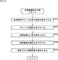
- This reference information presentation process is started when the "Reference" item in the operation menu is selected by the user.
- step S201 the acquisition unit 81 acquires the reference image from the external server 16 or the like.
- the acquired reference image is supplied to the control unit 82.
- the control unit 82 arranges the presentation information on the upper part of the surgical field image and, for example, arranges the thumbnail images of the reference information group on the left side and the right side of the display image, respectively, so that the display has the area configuration of A in FIG. Generate an image.
- the control unit 82 outputs the display image to the display control unit 83.
- the display control unit 83 outputs the display image supplied from the control unit 82 to the display device 14, and causes the display device 14 to present the reference information group.
- step S202 the control unit 82 accepts the user's selection of the thumbnail image of the reference information group.
- the control unit 82 detects the user's line of sight based on the captured image supplied from the camera installed in the vicinity of the display device 14.
- the control unit 82 identifies the reference information group selected by the user based on the detected line of sight of the user.
- step S203 the control unit 82 generates a display image as shown in the lower part of FIG. 17 by arranging the reference image included in the reference information group selected by the user under the display image.
- the control unit 82 outputs the display image to the display control unit 83.
- the display control unit 83 outputs the display image supplied from the control unit 82 to the display device 14, and causes the user to present a list of reference images included in the reference information group selected by the user.
- step S204 the control unit 82 accepts the user's selection of the reference image.
- the control unit 82 detects the user's line of sight based on the captured image supplied from the camera installed in the vicinity of the display device 14.
- the control unit 82 identifies the reference image selected by the user based on the detected line of sight of the user.
- step S205 the control unit 82 generates a display image as shown in the upper part of FIG. 18 by arranging the reference image selected by the user at the right end of the display image.
- the control unit 82 outputs the display image to the display control unit 83.
- the display control unit 83 outputs the display image supplied from the control unit 82 to the display device 14, and causes the display device 14 to present the reference image selected by the user.
- control device 12 can present the presented information and display the surgical field image and the reference image without hindering the concentration of the user.
- FIG. 24 is a diagram showing an example of a display image displayed on the display device 14 when "Move" is selected.
- the presentation information area A1 which is a narrow band-shaped area is placed on the surgical field image area A2 which is the area where the surgical field image is displayed. It is arranged so that the direction indicator areas A61-0 to A61-7 are arranged so as to overlap the surgical field image area A2.
- the display image of FIG. 24 is the same as the display image described with reference to FIG. 2, except that there is no operation menu area A3 and there are direction indicator areas A61-0 to A61-7, so that they overlap. The description will be omitted as appropriate.
- the direction indicator regions A61-1, A61-3, A61-5, and A61-7 are arranged at the four corners of the surgical field image region A2, respectively.
- the direction indicator area A61-0 is arranged at the center of the direction indicator areas A61-7 and A61-1
- the direction indicator area A61-2 is arranged at the center of the direction indicator areas A61-1 and A61-3.
- the turn signal area A61-4 is arranged at the center of the turn signal areas A61-3 and A61-5
- the turn signal area A61-6 is the center of the turn signal areas A61-5 and A61-7. It is located in.
- the direction indicator areas A61-0 to A61-7 include a display area of an indicator indicating a direction in which the display range of the displayed surgical field image can be changed.
- the name of the direction and the number indicating the direction are displayed as direction indicators in text.
- an icon indicating a direction is displayed as a direction indicator. With these displays, the user can intuitively recognize what operation should be performed next.
- the user can select the direction indicator displayed in the direction indicator areas A61-0 to A61-7 by the line of sight or voice, and change the display range of the surgical field image toward the selected direction. That is, the direction indicators displayed in the direction indicator areas A61-0 to A61-7 indicate the directions in which the angle of view of the surgical field image can be moved.
- the camera in the microscope device 11 may be driven to change the angle of view, or image processing may be performed on the captured image captured by the camera. Further, when a predetermined voice (voice command) is input, the display image may be configured to display a predetermined mark at the line-of-sight position of the user. Further, an operation of following the predetermined mark so that it becomes the center of the displayed image may be performed.
- the control device 12 displays a predetermined mark indicating the user's line-of-sight position on the display image so that the predetermined mark becomes the center position of the display image. Change the display of the surgical field image.
- the control device 12 may change the display range among the direction indicators displayed in the direction indicator areas A61-0 to A61-7. Generates a display image in which only direction indicators indicating possible directions are displayed.
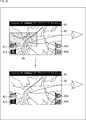
- FIG. 25 is a diagram showing an example of a displayed direction indicator.
- the display image is a display in which the direction indicator is displayed in the direction indicator areas A61-0 to A6-7. It becomes an image.
- the surgical field image whose display range is shifted to the right is displayed in the surgical field image area A2.
- the display range may be changed by performing predetermined image processing on the surgical field image supplied from the microscope device 11, or the control device 12 controls the microscope device 11 to control the surgical field image.
- the display range may be changed.
- the control device 12 controls the control device 12 as shown in the lower part of the arrow in FIG. A display image in which the direction indicators are displayed in the direction indicator areas A61-0 and the direction indicator areas A61-4 to A61-7 is generated.
- the three dashed circles on the display image indicate that the direction indicators displayed in the direction indicator areas A61-1 to A61-3 are hidden.
- the direction indicators displayed in the direction indicator areas A61-1 to A61-3 are direction indicators that represent the right direction, the diagonally upper right direction, and the diagonally lower right direction whose display range cannot be changed.
- control device 12 presents the direction in which the display range of the displayed surgical field image cannot be changed to the user by hiding the direction indicator indicating the direction.
- a display different from the direction indicator may indicate a direction in which the display range of the surgical field image cannot be changed.
- FIG. 26 is a diagram showing an example of a region configuration of a display image that presents a direction in which the display range of the surgical field image cannot be changed.
- a and B in FIG. 26 show display images in which the arrangement positions of the change limit information, which is information indicating the direction in which the display range of the surgical field image cannot be changed, are different.
- Each of the display images A and B in FIG. 26 is similar to the display image described with reference to FIG. 2 except that there is no operation menu area A3 and there is a display area for change limit information, so that they overlap. The description will be omitted as appropriate.
- Direction indicator areas A61-0 to A61-7 may be arranged on the display images of A and B in FIG. 26, and direction indicators may be displayed in each area.
- the change limit information area A71-1 which is a display area for change limit information, is arranged as a vertically long area at the right end of the display image.
- the change limit information area A71-1 for example, a monochromatic image in which a predetermined brightness is set is displayed.
- the display range of the surgical field image is continuously changed toward the right, and the operation is performed in the right direction, the diagonally upward right direction, and the diagonally downward right direction. It is generated by the control device 12 when the display range of the field image cannot be changed.
- the change limit information area A71-2 which is a display area of the change limit information, is arranged as an elongated band-shaped area at the lower end of the display image.
- the display image of B in FIG. 26 for example, as shown by the arrow D2, the display range of the surgical field image is continuously changed downward, and the operation is performed downward, diagonally downward to the left, and diagonally downward to the right. It is generated by the control device 12 when the display range of the field image cannot be changed.
- This display range change process is started when the "Move" item in the operation menu is selected by the user.
- step S301 the control unit 82 arranges the presentation information on the upper part of the surgical field image, and for example, arranges the direction indicators at the four corners of the surgical field image area A2 and the corners and the center positions of the corners. Generates the display image of FIG. 24.
- the control unit 82 outputs the display image to the display control unit 83.
- the display control unit 83 outputs the display image supplied from the control unit 82 to the display device 14, and causes the display device 14 to present a direction in which the display range of the surgical field image can be changed.
- step S302 the control unit 82 accepts the user's selection of the direction indicator.
- the control unit 82 detects the user's line of sight based on the captured image supplied from the camera installed in the vicinity of the display device 14.
- the control unit 82 identifies the direction indicator selected by the user based on the detected line of sight of the user.
- the control unit 82 generates a display image in which the display range of the surgical field image is changed according to the direction indicator selected by the user.
- the control unit 82 outputs the display image to the display control unit 83.
- the display control unit 83 outputs the display image supplied from the control unit 82 to the display device 14, and displays the display image in which the display range of the surgical field image is changed.
- step S303 the control unit 82 determines whether or not the display range can be changed.
- step S303 If it is determined in step S303 that the display range can be changed, the process proceeds to step S304.
- step S304 the control unit 82 generates, for example, a display image in which only the direction indicators in the directions in which the display range of the surgical field image can be changed are arranged among the direction indicators.
- the control unit 82 outputs the display image to the display control unit 83.
- the display control unit 83 outputs the display image supplied from the control unit 82 to the display device 14, and makes it present that the display range of the surgical field image can be changed as shown in B of FIG. 25. Further, as shown in FIG. 26, the change limit information may be displayed in a direction in which the display range of the surgical field image cannot be changed.
- step S305 the control unit 82 determines whether or not to end the display range change process based on the user's selection. If it is determined in step S303 that the display range of the surgical field image cannot be changed, step S304 is skipped, the process proceeds to step S305, and the display range change process is performed based on the user's selection. It is determined whether or not to terminate.
- step S305 If it is determined in step S305 that the display range change process is not completed, the process returns to step S301, and the subsequent processes are performed.
- step S305 if it is determined in step S305 that the display range change process is terminated, the display range change process is terminated.
- control device 12 can present the presented information and change the display range of the surgical field image without hindering the concentration of the user.
- Modification example> Example of display position adjustment by the work concentration area
- the control device 12 obtains a gazing point based on the line of sight of the user detected based on the captured image supplied from the camera installed in the vicinity of the display device 14. At this time, a predetermined work concentration area may be obtained by the control device 12 based on the distribution of the gazing points.
- the work concentration area is an area on the display image where the user is assumed to concentrate his / her eyes.
- a region in which the change within a predetermined time is larger than a predetermined amount may be determined as a work concentration region where the movement is large.
- an alert may be displayed at a predetermined position on the display image based on the requested work concentration area.
- FIG. 28 is a diagram showing an example of the area configuration of the display image on which the alert is displayed.
- the work concentration area A81 is obtained by the control device 12 as a substantially central circular area in the surgical field image area A2.
- alert # 1 is arranged in the vicinity of the work concentration area A81.
- alert # 1 is superposed on the surgical field image area A2.
- Alert # 1 is displayed based on information such as monitoring information.
- alert # 1 can be displayed by setting a predetermined transmittance.
- the work concentration area A81 is displayed for convenience of explanation, and is not actually displayed.
- the alert # 1 is arranged in the presentation information area A1 unlike the alert # 1 in A in FIG. 28.
- the alert # 1 is displayed in the presentation information area A1 in the same manner as the presentation information such as the monitoring information displayed in the presentation information area A1.
- the placement position of alert # 1 on the display image can be any position. Further, other information based on the monitoring information or the like may be displayed in the same manner as the alert # 1.
- the placement position of the information to be superposed on the surgical field image area A2 may be determined based on the obtained work concentration area.
- the arrangement position of the selection reference image area described in the third embodiment may be determined based on the work concentration area.
- FIG. 29 is a diagram showing an example of other area configurations of the displayed image on which the selected reference image is displayed.
- the upper circular area on the right side of the displayed image is the work concentration area A81.
- the control device 12 arranges the selection reference image area A41 at either the left or right end on the display image farther from the work concentration area A81.
- the reference image area A41-1 which is the display area of the reference image selected by the user is arranged at the left end on the display image.
- the lower circular area on the left side of the displayed image is the work concentration area A81.
- the selected reference image area A41-2 which is the display area of the reference image selected by the user, is displayed symmetrically with the selected reference image area A41-1 in the display image of FIG. 29A. It is located at the right end of the image.
- the user can control the area configuration of the displayed image by performing a predetermined operation.
- the user can display the display image described with reference to FIG. 2 by performing line-of-sight, voice, gesture, touch operation, and the like.
- the user can also display a display image composed of only the surgical field image area A2 by performing the same operation, for example.
- the display image composed of only the surgical field image area A2 may be displayed.
- FIG. 30 is a diagram showing an example of the area configuration of the display image on which the button is displayed.
- the button area A91 which is a button display area, is arranged in the diagonally lower right corner on the display image so as to be superimposed on the operation menu area A3 as a substantially square area.
- the surgical field image area A2 is arranged on the entire screen, and only the surgical field image is displayed.
- the user switches from the display image in a certain state to the display image in the initial state (display image in FIG. 2 or display image in B in FIG. 30) by performing a predetermined operation. It becomes possible.
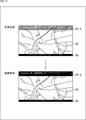
- control unit 82 When the item "Zoom" is selected in the operation menu, the control unit 82 generates a display image in which the surgical field image area A2 is divided.
- FIG. 31 is a diagram showing an example of a display image displayed on the display device 14 when "Zoom" is selected.
- the display image when "Zoom" is selected is configured by arranging the presentation information area A1 which is a narrow band-shaped area on the surgical field image area A2. ..
- the surgical field image region A2 is composed of rectangular surgical field image division regions A101-0 to A101-8.
- the surgical field image division area A101-0 is a region arranged in the center of the regions in which the surgical field image area A2 is divided into nine regions of 3 ⁇ 3 (vertical ⁇ horizontal).
- the surgical field image division areas A101-1 and A101-5 are rectangular areas arranged above and below the surgical field image division area A101-0 and having the same width and height.
- the surgical field image division regions A101-2, A101-4, A101-6, and A101-8 are rectangular regions having the same width and height, which are arranged at the respective corners of the surgical field image region A2.
- the surgical field image division areas A101-3 and A101-7 are rectangular shapes arranged on the right and left sides of the surgical field image division area A101-0, respectively, and have the same width and height.
- the surgical field image displayed in the surgical field image area A2 is divided and displayed in the surgical field image division areas A101-0 to A101-8. Further, in the surgical field image division areas A101-0 to A101-8, a number representing each area and a name of each area are displayed at predetermined positions of each area.
- the user can select the divided surgical field image displayed in the surgical field image division areas A101-0 to A101-8 by the line of sight or voice. For example, when the divided surgical field image displayed in the surgical field image division area A101-0 is selected, the control device 12 generates the lower display image shown at the tip of the arrow in FIG. 31.
- the surgical field image displayed in the surgical field image division area A101-0 is magnified four times and displayed in the surgical field image area A2.
- the broken line rectangle represents the region corresponding to the surgical field image division region A101-0.
- the control unit 82 enlarges the surgical field image displayed in the surgical field image displayed in the area selected by the user to a predetermined magnification and enlarges the surgical field image. It is arranged in the image area A2.
- the magnification for enlarging the surgical field image may be specified by the line of sight or voice after the user selects the surgical field image to be displayed in the surgical field image division area.
- the user can select the information to be displayed by combining multiple inputs such as line of sight and voice. For example, the user can combine the line of sight and the voice to select the thumbnail image of the reference information group described in the third embodiment.
- FIG. 32 is a diagram showing an example of operation by a combination of line of sight and voice.
- the user's line of sight is directed to the thumbnail image displayed in the reference information group area A11.
- This line of sight is a line of sight detected by the control device 12 based on the captured image supplied from the camera installed in the vicinity of the display device 14.
- the thumbnail image displayed in the reference information group area A11 to which the line of sight is directed is the same as the display image described with reference to FIG.
- the hatched thumbnail images displayed in the reference information group areas A12 to A14 indicate that the thumbnail images are displayed with a predetermined transmittance set.
- control unit 82 sets and displays the transmittance for the thumbnail images displayed in the reference information group areas A11 to A14 other than the thumbnail images to which the line of sight of the detected user is directed. Generate an image. That is, while the transmittance is not set for the thumbnail image to which the user's line of sight is directed and focused, the transmittance is set for the thumbnail images other than the thumbnail image.
- the user selects the thumbnail image in which the line of sight is directed by a predetermined voice (voice command) such as "select this". It is possible.
- the thumbnail image may be focused based on the area to which the user's line of sight is directed.
- FIG. 33 is a diagram showing an example of a display image in which the thumbnail image is focused based on the area to which the user's line of sight is directed.
- the control unit 82 determines, for example, the rectangular area R3 surrounded by the broken line as the area to which the user's line of sight is directed, based on the user's line of sight. Since the rectangular area R3 surrounded by the broken line includes only a part of the reference information group area A11 among the reference information group areas A11 to A14, the control unit 82 is in the lower part of the arrow in FIG. 33. Generate the display image shown in.
- the lower display image of FIG. 33 is the same as the display image described with reference to FIG. 32. That is, the control unit 82 does not set the transmittance for the thumbnail image included in the area to which the user's line of sight is directed, but sets the transmittance for the thumbnail images other than the thumbnail image to generate the display image. .. Then, after confirming the thumbnail image that is in focus, the user can select the thumbnail image by a predetermined voice.
- FIG. 34 is a diagram showing another example of operation by a combination of line of sight and voice.
- the user's line of sight is directed to a substantially central position on the surgical field image area A2.
- the marking M1 which is a flag icon is displayed at a position on the surgical field image area A2 to which the user's line of sight is directed.
- the control device 12 when the user emits a predetermined voice such as "marking" while directing the line of sight, the control device 12 generates a display image in which the marking M1 is superimposed and arranged at the position where the user's line of sight is directed. doing.
- the display image displayed after the predetermined voice (voice command) is input may be configured to display the user's line-of-sight position on the screen with a predetermined mark.
- the control device 12 displays a mark on the screen so as to follow the detected line-of-sight position of the user.
- the control device 12 may change the display range of the surgical field image following the position of the mark so that the position of the mark overlaps with the center position of the image.
- the presentation information displayed in the presentation information area A1 may include time information indicating the total operation time counted from the time when the operation is started.
- the presented information may include alert information, a set value of the pneumoperitoneum device, a set value of the electric knife, and information indicating a timer.
- the information indicating the timer for example, it is preferable to display the set time and the count-up time, and change the color of the characters when the count-up time reaches the set time.
- the control device 12 may display the content to be alerted as alert information.
- the operation menu displayed in the operation menu area A3 may be the operation menu shown in FIG. 36.
- the texts “Camera”, “Reference”, “Timer Start”, “Screen”, and “Others” representing the option items that can be selected by the user are displayed.
- the “Camera” is an item for causing the control device 12 to control the medical imaging device that is capturing the surgical field image or control the display of the surgical field image.
- “Timer Start” is an item for causing the control device 12 to start counting by the count-up timer.
- “Reference” is the same item as “Reference” in the above-described embodiment.
- “Screen” is an item for causing the control device 12 to switch the display state.
- Switching the display state is, for example, switching between display and non-display of the user interface, and switching ON and OFF of the full-screen display of the reference image.
- “Others” is an item for causing the control device 12 to perform other operations such as displaying a submenu.
- the control device 12 may display "Cancel", which is an item for canceling the content instructed by the user to the control device 12.
- the operation menu item displayed in the operation menu area A3 is changed to an item for controlling the medical imaging device or the display of the surgical field image.
- the texts “Zoom In”, “Zoom Out”, “Zoom Reset”, “Center”, “Move”, and “Cancel” representing the option items that can be selected by the user are displayed.
- “Zoom In” is an item for causing the control device 12 to control to increase the magnification of the surgical field image.
- “Zoom Out” is an item for causing the control device 12 to control the magnification of the surgical field image to be reduced.
- Zero Adjust Reset is an item for causing the control device 12 to control the magnification of the surgical field image to a specified value
- Center is an item for controlling the control device 12 to return the magnification of the surgical field image to a specified value. This is an item for controlling the center to be aligned with the center of the display device.
- Move is the same item as “Move” in the above-described embodiment.
- “Cancel” is an item for causing the control device 12 to cancel the content instructed by the user to the control device 12 in the past.
- the control device 12 displays an operation item for causing the display device 12 to control the display of the reference image in the lower areas of the selected reference image areas A41 and A42. May be good.
- FIG. 38A when a plurality of reference images are displayed, it is preferable to display the operation item in the lower area of the selected reference image area in which each reference image is displayed.
- the operation items include, for example, "Enlarge” for controlling the display of a large image, "Close” for canceling the display of the reference image, and the like.
- the control device 12 selects "Full Size” for displaying the reference image in the entire display area and "Half Size” for displaying the reference image in half of the display area.
- the control device 12 sets the lower region of the reference image (selected reference image) in which the detected user's line-of-sight position and the display area overlap from the lower region of the other reference image (non-selected reference image). It may be displayed darker. As a result, the control device 12 can present the user with a reference image to be operated by voice control.
- the control device 12 divides the surgical field image region A2 into two regions in the horizontal direction according to a user's instruction, one of which is the surgical field image, and the other of which is a reference image or a predetermined enlargement. It may be configured to display a surgical field image enlarged at a magnification.
- the item "Half size” may be added to the item of the operation menu as an item for the user to instruct the control device 12 to divide the display area. Further, when the user has selected "Half Size", "Cancel Half size” may be added to the item of the operation menu as an item for causing the control device 12 to cancel the instruction of dividing the area.
- the image to be arranged may be determined based on the user's voice. Further, here, as the line-of-sight area corresponding process regarding the line-of-sight area according to the user's line-of-sight, a process of selecting the selection target according to the user's voice when the selection target exists in the line-of-sight area, and a process of selecting the selection target according to the user's voice. Although the process of marking the position indicated by the line-of-sight area or the process of focusing on the selection target in the line-of-sight area has been illustrated, other processes may be performed.
- the program executed by the control device 12 may be a program in which processing is performed in chronological order in the order described in this specification, or is necessary in parallel or when a call is made. It may be a program in which processing is performed at the timing.
- the series of processes described above can be executed by hardware or software.
- the programs constituting the software are installed on a computer embedded in dedicated hardware or a general-purpose personal computer.
- the installed program is provided by recording on a removable recording medium 61 shown in FIG. 7, which consists of an optical disk (CD-ROM (Compact Disc-Read Only Memory), DVD (Digital Versatile Disc), etc.), a semiconductor memory, or the like. .. It may also be provided via a wired or wireless transmission medium such as a local area network, the Internet, or digital broadcasting.
- the program can be pre-installed in the ROM 52 or the recording unit 58.
- the program executed by the computer may be a program that is processed in chronological order in the order described in this specification, or may be a program that is processed in parallel or at a necessary timing such as when a call is made. It may be a program in which processing is performed.
- the system means a set of a plurality of components (devices, modules (parts), etc.), and it does not matter whether all the components are in the same housing. Therefore, a plurality of devices housed in separate housings and connected via a network, and a device in which a plurality of modules are housed in one housing are both systems. ..
- this technology can have a cloud computing configuration in which one function is shared by a plurality of devices via a network and processed jointly.
- each step described in the above flowchart can be executed by one device or shared by a plurality of devices.
- one step includes a plurality of processes
- the plurality of processes included in the one step can be executed by one device or shared by a plurality of devices.
- the present technology can also have the following configurations.
- An acquisition unit that acquires a surgical field image signal generated by a medical imaging device that images a patient's surgical field and a presentation information signal generated by a device including an external device excluding the medical imaging device.
- a control device including a control unit that generates a display image based on the surgical field image signal and the presentation information signal is provided.
- the control unit arranges the presentation information generated from the presentation information signal in the upper region of the display area of the display image, and performs the operation in the middle region having the same length in the horizontal direction as the upper region.
- the surgical field image generated based on the field image signal is arranged, the user interface information for controlling the control device is arranged in the area below the upper area, and the display image is generated so as to be displayed.
- Medical display system is provided.
- the presented information includes at least monitoring information generated from a monitoring information signal acquired from a monitoring device that monitors the biological information of the patient.
- the control unit arranges the presented information in a predetermined display form including a text or a graph.
- the presented information includes information regarding surgical instruments.
- the presented information includes information regarding time.
- the presented information includes information that changes in real time.
- the surgical field image is an image that changes in real time.
- the region below the upper region includes a lower region having a horizontal equivalent length as the upper region.
- the region below the upper region includes regions having different lengths in the horizontal direction from the upper region, and includes left and right regions corresponding to at least one of the left and right ends of the middle region.
- the control unit changes a display method of the presented information arranged in the upper region based on information about the user.
- the control unit arranges one or a plurality of captured images generated by another medical imaging device different from the medical imaging device in a region below the upper region (1) to (11). The medical display system described in either.
- the control unit Place a thumbnail image corresponding to the reference image, which is a captured image for reference, When the thumbnail image is selected, a plurality of reference images corresponding to the selected thumbnail image are arranged side by side in a predetermined direction.
- the medical display system according to (12) above, wherein when a desired reference image is selected from the plurality of reference images, a reference image obtained by enlarging the selected reference image is arranged.
- the control unit arranges a direction indicator for changing the display range of the surgical field image in a region below the upper region. system.
- the control unit Identify the work concentration area where the user focused his eyes on the surgical field image,
- the medical display system according to any one of (1) to (14) above, which determines the arrangement position of information superimposed on the surgical field image based on the specified work concentration area.
- the control unit Detecting the user's line of sight to the central region, The medical display system according to any one of (1) to (16) above, which performs a line-of-sight area correspondence process for a line-of-sight area according to the detected line-of-sight.
- the line-of-sight area correspondence process is a process of selecting the selection target according to the voice of the user when a selection target exists in the line-of-sight area, and marking a position indicated by the line-of-sight area according to the voice of the user.
- the medical display system which includes a process of performing the process or a process of focusing on the selected object in the line-of-sight region.
- An acquisition unit that acquires a surgical field image signal generated by a medical imaging device that images a patient's surgical field and a presentation information signal generated by a device including an external device excluding the medical imaging device.
- a control unit that generates a display image based on the surgical field image signal and the presentation information signal is provided. The control unit arranges the presentation information generated from the presentation information signal in the upper region of the display area of the display image, and performs the operation in the middle region having the same length in the horizontal direction as the upper region.
- the control device The surgical field image signal generated by the medical imaging device that images the surgical field of the patient and the presentation information signal generated by the device including the external device excluding the medical imaging device are acquired.
- a display image is generated based on the surgical field image signal and the presentation information signal.
- the presentation information generated from the presentation information signal is arranged in the upper region, and the central region having the same length in the horizontal direction as the upper region is based on the surgical field image signal.
- a control method in which a surgical field image generated is arranged, user interface information for controlling a control device is arranged in an area below the upper area, and the display image is generated so as to be displayed.
- 1 medical display system 11 microscope device, 12 control device, 13 monitoring device, 14 display device, 15 network, 16 external server, 81 acquisition unit, 82 control unit, 83 display control unit
Landscapes
- Engineering & Computer Science (AREA)
- Health & Medical Sciences (AREA)
- Theoretical Computer Science (AREA)
- General Engineering & Computer Science (AREA)
- Life Sciences & Earth Sciences (AREA)
- Surgery (AREA)
- Physics & Mathematics (AREA)
- Human Computer Interaction (AREA)
- General Physics & Mathematics (AREA)
- General Health & Medical Sciences (AREA)
- Nuclear Medicine, Radiotherapy & Molecular Imaging (AREA)
- Veterinary Medicine (AREA)
- Animal Behavior & Ethology (AREA)
- Public Health (AREA)
- Molecular Biology (AREA)
- Medical Informatics (AREA)
- Biomedical Technology (AREA)
- Heart & Thoracic Surgery (AREA)
- Multimedia (AREA)
- Pathology (AREA)
- Oral & Maxillofacial Surgery (AREA)
- Audiology, Speech & Language Pathology (AREA)
- Robotics (AREA)
- Radiology & Medical Imaging (AREA)
- Signal Processing (AREA)
- Gynecology & Obstetrics (AREA)
- Biophysics (AREA)
- Optics & Photonics (AREA)
- User Interface Of Digital Computer (AREA)
- Measuring And Recording Apparatus For Diagnosis (AREA)
Abstract
Priority Applications (2)
| Application Number | Priority Date | Filing Date | Title |
|---|---|---|---|
| US17/597,120 US12263044B2 (en) | 2019-07-05 | 2020-07-03 | Medical display system, control device, and control method |
| JP2021530671A JP7632284B2 (ja) | 2019-07-05 | 2020-07-03 | 医療用表示システム、制御装置、および制御方法 |
Applications Claiming Priority (2)
| Application Number | Priority Date | Filing Date | Title |
|---|---|---|---|
| JP2019-126311 | 2019-07-05 | ||
| JP2019126311 | 2019-07-05 |
Publications (1)
| Publication Number | Publication Date |
|---|---|
| WO2021006201A1 true WO2021006201A1 (fr) | 2021-01-14 |
Family
ID=74114158
Family Applications (1)
| Application Number | Title | Priority Date | Filing Date |
|---|---|---|---|
| PCT/JP2020/026167 Ceased WO2021006201A1 (fr) | 2019-07-05 | 2020-07-03 | Système d'affichage médical, dispositif de commande et procédé de commande |
Country Status (3)
| Country | Link |
|---|---|
| US (1) | US12263044B2 (fr) |
| JP (1) | JP7632284B2 (fr) |
| WO (1) | WO2021006201A1 (fr) |
Cited By (2)
| Publication number | Priority date | Publication date | Assignee | Title |
|---|---|---|---|---|
| EP4353183A4 (fr) * | 2021-06-03 | 2024-10-02 | Sony Group Corporation | Dispositif de traitement d'informations, système de traitement d'informations, procédé de traitement d'informations, et programme |
| JP7587898B1 (ja) | 2024-05-17 | 2024-11-21 | Direava株式会社 | 情報処理装置、方法、およびプログラム |
Citations (3)
| Publication number | Priority date | Publication date | Assignee | Title |
|---|---|---|---|---|
| WO2016021232A1 (fr) * | 2014-08-04 | 2016-02-11 | オリンパス株式会社 | Système de traitement médical |
| JP2018143559A (ja) * | 2017-03-07 | 2018-09-20 | ソニー・オリンパスメディカルソリューションズ株式会社 | 医療用画像表示装置、および表示制御方法 |
| JP2018161377A (ja) * | 2017-03-27 | 2018-10-18 | ソニー株式会社 | 医療用システムの制御装置、医療用システムの制御方法及び医療用システム |
Family Cites Families (5)
| Publication number | Priority date | Publication date | Assignee | Title |
|---|---|---|---|---|
| US20120189173A1 (en) | 2011-01-26 | 2012-07-26 | Markowitz H Toby | Image display |
| JP5731267B2 (ja) | 2011-04-25 | 2015-06-10 | 株式会社日立メディコ | 治療支援システム及び医用画像処理装置 |
| US9681982B2 (en) | 2012-12-17 | 2017-06-20 | Alcon Research, Ltd. | Wearable user interface for use with ocular surgical console |
| GB2525817B (en) * | 2013-03-12 | 2020-02-26 | Opternative Inc | Computerized refraction and astigmatism determination |
| JP2017174043A (ja) | 2016-03-23 | 2017-09-28 | パイオニア株式会社 | 表示装置 |
-
2020
- 2020-07-03 WO PCT/JP2020/026167 patent/WO2021006201A1/fr not_active Ceased
- 2020-07-03 US US17/597,120 patent/US12263044B2/en active Active
- 2020-07-03 JP JP2021530671A patent/JP7632284B2/ja active Active
Patent Citations (3)
| Publication number | Priority date | Publication date | Assignee | Title |
|---|---|---|---|---|
| WO2016021232A1 (fr) * | 2014-08-04 | 2016-02-11 | オリンパス株式会社 | Système de traitement médical |
| JP2018143559A (ja) * | 2017-03-07 | 2018-09-20 | ソニー・オリンパスメディカルソリューションズ株式会社 | 医療用画像表示装置、および表示制御方法 |
| JP2018161377A (ja) * | 2017-03-27 | 2018-10-18 | ソニー株式会社 | 医療用システムの制御装置、医療用システムの制御方法及び医療用システム |
Cited By (3)
| Publication number | Priority date | Publication date | Assignee | Title |
|---|---|---|---|---|
| EP4353183A4 (fr) * | 2021-06-03 | 2024-10-02 | Sony Group Corporation | Dispositif de traitement d'informations, système de traitement d'informations, procédé de traitement d'informations, et programme |
| JP7587898B1 (ja) | 2024-05-17 | 2024-11-21 | Direava株式会社 | 情報処理装置、方法、およびプログラム |
| JP2025174456A (ja) * | 2024-05-17 | 2025-11-28 | Direava株式会社 | 情報処理装置、方法、およびプログラム |
Also Published As
| Publication number | Publication date |
|---|---|
| US20220265384A1 (en) | 2022-08-25 |
| JP7632284B2 (ja) | 2025-02-19 |
| JPWO2021006201A1 (fr) | 2021-01-14 |
| US12263044B2 (en) | 2025-04-01 |
Similar Documents
| Publication | Publication Date | Title |
|---|---|---|
| KR102893139B1 (ko) | 내시경 비디오 뷰 내에서 뷰잉가능 면적을 자동으로 리포지셔닝하기 위한 방법 및 시스템 | |
| US11615503B2 (en) | Information processing apparatus, method and computer-readable medium | |
| JP4653557B2 (ja) | 医用画像表示装置及び医用画像表示方法 | |
| JP5904812B2 (ja) | 医療ディスプレイのための外科医の補助 | |
| JPWO2006077798A1 (ja) | 医療機器データ解析装置 | |
| RU2469308C2 (ru) | Рентгеновский инструмент для трехмерного ультразвукового исследования | |
| TWI774460B (zh) | 病人資訊呈現方法及電子裝置 | |
| JP2020081280A (ja) | 画像表示制御システム、画像表示システム及び画像解析装置 | |
| JP7632284B2 (ja) | 医療用表示システム、制御装置、および制御方法 | |
| US20070182729A1 (en) | Apparatus for interventional therapy | |
| JP6852612B2 (ja) | 表示プログラム、情報処理装置、及び表示方法 | |
| WO2009122863A1 (fr) | Système d’affichage d’image et programme d’affichage d’image | |
| CN100498761C (zh) | 医疗图像显示设备 | |
| JP6578519B2 (ja) | 画像表示装置、画像表示システム、画像表示方法、およびプログラム | |
| JP7382735B2 (ja) | 医用情報処理システム | |
| JPWO2018087977A1 (ja) | 情報処理装置、情報処理方法、プログラム | |
| JP6440136B1 (ja) | 医療映像スイッチャー | |
| US20070016018A1 (en) | Review mode graphical user interface for an ultrasound imaging system | |
| JP7099064B2 (ja) | 表示制御装置、医用画像表示システム及びプログラム | |
| JPH0199084A (ja) | 画像処理装置 | |
| JPWO2022195696A5 (fr) | ||
| JP5789369B2 (ja) | X線画像表示装置 | |
| JP2006110208A (ja) | 医用画像表示装置 | |
| JPH08263634A (ja) | 画像処理方法および装置 | |
| US20230025725A1 (en) | Storage medium, medical image display apparatus and medical image display system |
Legal Events
| Date | Code | Title | Description |
|---|---|---|---|
| 121 | Ep: the epo has been informed by wipo that ep was designated in this application |
Ref document number: 20836996 Country of ref document: EP Kind code of ref document: A1 |
|
| ENP | Entry into the national phase |
Ref document number: 2021530671 Country of ref document: JP Kind code of ref document: A |
|
| 122 | Ep: pct application non-entry in european phase |
Ref document number: 20836996 Country of ref document: EP Kind code of ref document: A1 |
|
| WWG | Wipo information: grant in national office |
Ref document number: 17597120 Country of ref document: US |