WO2021009999A1 - Structure de ventilation et de conditionnement de l'air, et procédé de ventilation et de conditionnement de l'air - Google Patents
Structure de ventilation et de conditionnement de l'air, et procédé de ventilation et de conditionnement de l'air Download PDFInfo
- Publication number
- WO2021009999A1 WO2021009999A1 PCT/JP2020/018782 JP2020018782W WO2021009999A1 WO 2021009999 A1 WO2021009999 A1 WO 2021009999A1 JP 2020018782 W JP2020018782 W JP 2020018782W WO 2021009999 A1 WO2021009999 A1 WO 2021009999A1
- Authority
- WO
- WIPO (PCT)
- Prior art keywords
- air
- ventilation
- wall portion
- room
- outside air
- Prior art date
- Legal status (The legal status is an assumption and is not a legal conclusion. Google has not performed a legal analysis and makes no representation as to the accuracy of the status listed.)
- Ceased
Links
Images



Classifications
-
- F—MECHANICAL ENGINEERING; LIGHTING; HEATING; WEAPONS; BLASTING
- F24—HEATING; RANGES; VENTILATING
- F24F—AIR-CONDITIONING; AIR-HUMIDIFICATION; VENTILATION; USE OF AIR CURRENTS FOR SCREENING
- F24F7/00—Ventilation
- F24F7/007—Ventilation with forced flow
- F24F7/013—Ventilation with forced flow using wall or window fans, displacing air through the wall or window
-
- F—MECHANICAL ENGINEERING; LIGHTING; HEATING; WEAPONS; BLASTING
- F24—HEATING; RANGES; VENTILATING
- F24F—AIR-CONDITIONING; AIR-HUMIDIFICATION; VENTILATION; USE OF AIR CURRENTS FOR SCREENING
- F24F1/00—Room units for air-conditioning, e.g. separate or self-contained units or units receiving primary air from a central station
- F24F1/0007—Indoor units, e.g. fan coil units
- F24F1/0035—Indoor units, e.g. fan coil units characterised by introduction of outside air to the room
-
- B—PERFORMING OPERATIONS; TRANSPORTING
- B01—PHYSICAL OR CHEMICAL PROCESSES OR APPARATUS IN GENERAL
- B01D—SEPARATION
- B01D46/00—Filters or filtering processes specially modified for separating dispersed particles from gases or vapours
- B01D46/0027—Filters or filtering processes specially modified for separating dispersed particles from gases or vapours with additional separating or treating functions
- B01D46/0028—Filters or filtering processes specially modified for separating dispersed particles from gases or vapours with additional separating or treating functions provided with antibacterial or antifungal means
-
- B—PERFORMING OPERATIONS; TRANSPORTING
- B01—PHYSICAL OR CHEMICAL PROCESSES OR APPARATUS IN GENERAL
- B01D—SEPARATION
- B01D46/00—Filters or filtering processes specially modified for separating dispersed particles from gases or vapours
- B01D46/42—Auxiliary equipment or operation thereof
- B01D46/4263—Means for active heating or cooling
-
- F—MECHANICAL ENGINEERING; LIGHTING; HEATING; WEAPONS; BLASTING
- F24—HEATING; RANGES; VENTILATING
- F24F—AIR-CONDITIONING; AIR-HUMIDIFICATION; VENTILATION; USE OF AIR CURRENTS FOR SCREENING
- F24F1/00—Room units for air-conditioning, e.g. separate or self-contained units or units receiving primary air from a central station
- F24F1/0007—Indoor units, e.g. fan coil units
- F24F1/0035—Indoor units, e.g. fan coil units characterised by introduction of outside air to the room
- F24F1/0038—Indoor units, e.g. fan coil units characterised by introduction of outside air to the room in combination with simultaneous exhaustion of inside air
-
- F—MECHANICAL ENGINEERING; LIGHTING; HEATING; WEAPONS; BLASTING
- F24—HEATING; RANGES; VENTILATING
- F24F—AIR-CONDITIONING; AIR-HUMIDIFICATION; VENTILATION; USE OF AIR CURRENTS FOR SCREENING
- F24F1/00—Room units for air-conditioning, e.g. separate or self-contained units or units receiving primary air from a central station
- F24F1/02—Self-contained room units for air-conditioning, i.e. with all apparatus for treatment installed in a common casing
- F24F1/022—Self-contained room units for air-conditioning, i.e. with all apparatus for treatment installed in a common casing comprising a compressor cycle
- F24F1/027—Self-contained room units for air-conditioning, i.e. with all apparatus for treatment installed in a common casing comprising a compressor cycle mounted in wall openings, e.g. in windows
-
- F—MECHANICAL ENGINEERING; LIGHTING; HEATING; WEAPONS; BLASTING
- F24—HEATING; RANGES; VENTILATING
- F24F—AIR-CONDITIONING; AIR-HUMIDIFICATION; VENTILATION; USE OF AIR CURRENTS FOR SCREENING
- F24F1/00—Room units for air-conditioning, e.g. separate or self-contained units or units receiving primary air from a central station
- F24F1/02—Self-contained room units for air-conditioning, i.e. with all apparatus for treatment installed in a common casing
- F24F1/032—Self-contained room units for air-conditioning, i.e. with all apparatus for treatment installed in a common casing characterised by heat exchangers
- F24F1/0323—Self-contained room units for air-conditioning, i.e. with all apparatus for treatment installed in a common casing characterised by heat exchangers by the mounting or arrangement of the heat exchangers
-
- F—MECHANICAL ENGINEERING; LIGHTING; HEATING; WEAPONS; BLASTING
- F24—HEATING; RANGES; VENTILATING
- F24F—AIR-CONDITIONING; AIR-HUMIDIFICATION; VENTILATION; USE OF AIR CURRENTS FOR SCREENING
- F24F1/00—Room units for air-conditioning, e.g. separate or self-contained units or units receiving primary air from a central station
- F24F1/02—Self-contained room units for air-conditioning, i.e. with all apparatus for treatment installed in a common casing
- F24F1/0328—Self-contained room units for air-conditioning, i.e. with all apparatus for treatment installed in a common casing with means for purifying supplied air
- F24F1/035—Self-contained room units for air-conditioning, i.e. with all apparatus for treatment installed in a common casing with means for purifying supplied air characterised by the mounting or arrangement of filters
-
- F—MECHANICAL ENGINEERING; LIGHTING; HEATING; WEAPONS; BLASTING
- F24—HEATING; RANGES; VENTILATING
- F24F—AIR-CONDITIONING; AIR-HUMIDIFICATION; VENTILATION; USE OF AIR CURRENTS FOR SCREENING
- F24F1/00—Room units for air-conditioning, e.g. separate or self-contained units or units receiving primary air from a central station
- F24F1/06—Separate outdoor units, e.g. outdoor unit to be linked to a separate room comprising a compressor and a heat exchanger
- F24F1/60—Arrangement or mounting of the outdoor unit
-
- F—MECHANICAL ENGINEERING; LIGHTING; HEATING; WEAPONS; BLASTING
- F24—HEATING; RANGES; VENTILATING
- F24F—AIR-CONDITIONING; AIR-HUMIDIFICATION; VENTILATION; USE OF AIR CURRENTS FOR SCREENING
- F24F11/00—Control or safety arrangements
- F24F11/30—Control or safety arrangements for purposes related to the operation of the system, e.g. for safety or monitoring
- F24F11/46—Improving electric energy efficiency or saving
-
- F—MECHANICAL ENGINEERING; LIGHTING; HEATING; WEAPONS; BLASTING
- F24—HEATING; RANGES; VENTILATING
- F24F—AIR-CONDITIONING; AIR-HUMIDIFICATION; VENTILATION; USE OF AIR CURRENTS FOR SCREENING
- F24F11/00—Control or safety arrangements
- F24F11/70—Control systems characterised by their outputs; Constructional details thereof
- F24F11/80—Control systems characterised by their outputs; Constructional details thereof for controlling the temperature of the supplied air
- F24F11/81—Control systems characterised by their outputs; Constructional details thereof for controlling the temperature of the supplied air by controlling the air supply to heat-exchangers or bypass channels
-
- F—MECHANICAL ENGINEERING; LIGHTING; HEATING; WEAPONS; BLASTING
- F24—HEATING; RANGES; VENTILATING
- F24F—AIR-CONDITIONING; AIR-HUMIDIFICATION; VENTILATION; USE OF AIR CURRENTS FOR SCREENING
- F24F12/00—Use of energy recovery systems in air conditioning, ventilation or screening
-
- F—MECHANICAL ENGINEERING; LIGHTING; HEATING; WEAPONS; BLASTING
- F24—HEATING; RANGES; VENTILATING
- F24F—AIR-CONDITIONING; AIR-HUMIDIFICATION; VENTILATION; USE OF AIR CURRENTS FOR SCREENING
- F24F13/00—Details common to, or for air-conditioning, air-humidification, ventilation or use of air currents for screening
- F24F13/20—Casings or covers
-
- F—MECHANICAL ENGINEERING; LIGHTING; HEATING; WEAPONS; BLASTING
- F24—HEATING; RANGES; VENTILATING
- F24F—AIR-CONDITIONING; AIR-HUMIDIFICATION; VENTILATION; USE OF AIR CURRENTS FOR SCREENING
- F24F13/00—Details common to, or for air-conditioning, air-humidification, ventilation or use of air currents for screening
- F24F13/28—Arrangement or mounting of filters
-
- F—MECHANICAL ENGINEERING; LIGHTING; HEATING; WEAPONS; BLASTING
- F24—HEATING; RANGES; VENTILATING
- F24F—AIR-CONDITIONING; AIR-HUMIDIFICATION; VENTILATION; USE OF AIR CURRENTS FOR SCREENING
- F24F13/00—Details common to, or for air-conditioning, air-humidification, ventilation or use of air currents for screening
- F24F13/30—Arrangement or mounting of heat-exchangers
-
- F—MECHANICAL ENGINEERING; LIGHTING; HEATING; WEAPONS; BLASTING
- F24—HEATING; RANGES; VENTILATING
- F24F—AIR-CONDITIONING; AIR-HUMIDIFICATION; VENTILATION; USE OF AIR CURRENTS FOR SCREENING
- F24F7/00—Ventilation
- F24F7/04—Ventilation with ducting systems, e.g. by double walls; with natural circulation
- F24F7/06—Ventilation with ducting systems, e.g. by double walls; with natural circulation with forced air circulation, e.g. by fan positioning of a ventilator in or against a conduit
- F24F7/10—Ventilation with ducting systems, e.g. by double walls; with natural circulation with forced air circulation, e.g. by fan positioning of a ventilator in or against a conduit with air supply, or exhaust, through perforated wall, floor or ceiling
-
- B—PERFORMING OPERATIONS; TRANSPORTING
- B01—PHYSICAL OR CHEMICAL PROCESSES OR APPARATUS IN GENERAL
- B01D—SEPARATION
- B01D2279/00—Filters adapted for separating dispersed particles from gases or vapours specially modified for specific uses
- B01D2279/50—Filters adapted for separating dispersed particles from gases or vapours specially modified for specific uses for air conditioning
-
- F—MECHANICAL ENGINEERING; LIGHTING; HEATING; WEAPONS; BLASTING
- F24—HEATING; RANGES; VENTILATING
- F24F—AIR-CONDITIONING; AIR-HUMIDIFICATION; VENTILATION; USE OF AIR CURRENTS FOR SCREENING
- F24F11/00—Control or safety arrangements
- F24F11/30—Control or safety arrangements for purposes related to the operation of the system, e.g. for safety or monitoring
-
- F—MECHANICAL ENGINEERING; LIGHTING; HEATING; WEAPONS; BLASTING
- F24—HEATING; RANGES; VENTILATING
- F24F—AIR-CONDITIONING; AIR-HUMIDIFICATION; VENTILATION; USE OF AIR CURRENTS FOR SCREENING
- F24F3/00—Air-conditioning systems in which conditioned primary air is supplied from one or more central stations to distributing units in the rooms or spaces where it may receive secondary treatment; Apparatus specially designed for such systems
- F24F3/044—Systems in which all treatment is given in the central station, i.e. all-air systems
- F24F2003/0448—Systems in which all treatment is given in the central station, i.e. all-air systems with two air ducts for separately transporting treated hot and cold air from the central station to the rooms
-
- F—MECHANICAL ENGINEERING; LIGHTING; HEATING; WEAPONS; BLASTING
- F24—HEATING; RANGES; VENTILATING
- F24F—AIR-CONDITIONING; AIR-HUMIDIFICATION; VENTILATION; USE OF AIR CURRENTS FOR SCREENING
- F24F2221/00—Details or features not otherwise provided for
- F24F2221/17—Details or features not otherwise provided for mounted in a wall
-
- F—MECHANICAL ENGINEERING; LIGHTING; HEATING; WEAPONS; BLASTING
- F24—HEATING; RANGES; VENTILATING
- F24F—AIR-CONDITIONING; AIR-HUMIDIFICATION; VENTILATION; USE OF AIR CURRENTS FOR SCREENING
- F24F2221/00—Details or features not otherwise provided for
- F24F2221/20—Details or features not otherwise provided for mounted in or close to a window
Definitions
- the present invention relates to a ventilation air conditioning structure and a ventilation air conditioning method. Specifically, it is easy to install and maintain in either new or existing buildings, and the power consumption of the air conditioner using an outside air conditioner that works with the air conditioner during air conditioning in the room.
- the temperature of the outside air hereinafter referred to as "harmonic air” heated or cooled by the outside air conditioner is utilized by utilizing the flow of the heated or cooled air (hereinafter referred to as "harmonic air”) blown from the air conditioner.
- the present invention relates to a ventilation and air conditioning structure capable of circulating (hereinafter referred to as "harmonious outside air”) in the room, and a ventilation and air conditioning method.
- the air conditioner 9 shown in FIG. 14 is an outside air conditioner 91 installed outdoors to process the outside air OA, and a return air intake port 92 for collecting the air RA supplied to the room R via the outside air conditioner 91. It has a sensible heat exchanger 93 installed in the vicinity. Here, the sensible heat exchanger 93 exchanges heat with the recovered air RA, and supplies the air SA after the heat exchange from the air supply port to the indoor R.
- the outside air harmonizer 91 includes a cooling coil 911, a heating coil 912, a humidifier 913, and a blower 914, and sends the introduced outside air OA to the indoor R side after temperature control and humidification.
- the outside air conditioner 91 is installed behind the ceiling (outdoor on the ceiling side) so that the air conditioner 91 does not get in the way (see paragraph [0019] of Patent Document 1, FIG. 2). It is also necessary to form or install circulation paths 94a and 94b for introducing and discharging the harmonious outside air into the indoor R.
- outside air harmonizing machine 91 since the outside air harmonizing machine 91 is equipped with the blower 914 and requires a mechanism for circulating the heat medium, electric power for operating the outside air harmonizing machine 91 is required.
- an air conditioner is usually installed indoors, and in such a case, two units, an outside air conditioner 91 and an air conditioner, will operate, and the electric power required for ventilation and air conditioning will be generated. It will inevitably increase.
- the present invention was devised in view of the above points, is easy to install and maintain in either a new construction or an existing building, and is an outside air interlocking with an air conditioner during air conditioning operation in a room. Ventilation that can reduce the power consumption of the air conditioner by using the air conditioner and can circulate the conditioned outside air into the room by using the flow of the conditioned air blown from the air conditioner. It is an object of the present invention to provide an air conditioning structure and a ventilation air conditioning method.
- the ventilation and air conditioning structure of the present invention has a wall portion for partitioning the inside and outside of a room in a building, and at least one surface of the wall portion is an outer wall portion in contact with the outside, and the outer wall portion.
- a first ventilation port is formed in the vicinity of one adjacent wall portion
- a second ventilation port is formed in the vicinity of the other adjacent wall portion
- the room structure is arranged in the room structure.
- a heat exchanger provided on the refrigerant circuit of the air conditioner via a branch pipe branched from the refrigerant pipe, which is arranged on the outside, and a first opening which opens downward while accommodating the heat exchanger.
- a second opening is formed in the back portion facing the outer wall portion, and the second opening is provided with an outside air harmonizer having a casing communicating with either the first ventilation port or the second ventilation port.
- the room structure has a wall portion that divides the inside and outside of the room, and at least one surface of the wall portion is an outer wall portion that constitutes the outer wall of the building, so that the vertical direction and the four sides between the upper and lower sides are closed.
- At least one wall surface is a structure having an internal space facing the outside.
- One of the room structures has a first ventilation port formed in the vicinity of one adjacent wall portion and a second ventilation port formed in the vicinity of the other adjacent wall portion on the outer wall portion thereof.
- the ventilation port When the ventilation port is used as an air supply port, the other ventilation port becomes an exhaust port, and air can be supplied and exhausted to and from the outside. Since the first ventilation port and the second ventilation port are arranged apart from each other on the outer wall portion, it is difficult for the fresh outside air immediately after entering from the air supply side to be immediately discharged from the exhaust side. It has become.
- the air conditioner has an indoor unit arranged inside the room structure and a refrigerant pipe connecting the indoor unit and the outdoor unit, so that the refrigerant circulates between the indoor unit and the outdoor unit through the refrigerant pipe. Heat exchange with the air inside the room structure is performed, and conditioned air, which is cold air or warm air, can be supplied to the room structure.
- the indoor unit can blow the air sucked from the intake port toward the wall portion facing the outer wall portion, so that the fresh outside air that has entered from the ventilation port on the air supply side is blown out from the indoor unit. It can be applied to the wall portion facing the outer wall portion by riding on the flow of.
- the air that is a mixture of the outside air and the conditioned air that hits the wall portion diffuses in the vertical and horizontal directions of the wall portion facing the outer wall portion and circulates in the room structure.
- CO 2 equal concentration concentration of carbon dioxide and chemical substances such as volatile organic compounds
- the indoor unit (at least one in the case of a plurality of units) is preferably arranged near the ventilation port on the air supply side of the outer wall or on the ceiling, and in this arrangement, the ventilation on the air supply side.
- the fresh outside air that has entered through the mouth can easily get on the flow of the conditioned air, and can be taken into the indoor unit before much heat of the conditioned outside air heated or cooled by the outside air harmonizer is lost. Further, for example, when the indoor unit has a plurality of air outlets, it is sufficient that at least one of them can blow air in the direction of the wall portion facing the outer wall portion.
- the ventilation port (for example, the first ventilation port) communicating with the outlet of the outside air conditioner serves as an air supply port for the room, and the other ventilation port (for example, the second ventilation port) serves as an exhaust port.
- the ventilation port on the exhaust side can exhaust the air in the room structure and reduce the CO 2 equal concentration in the room structure.
- the ventilation port on the exhaust side is preferably a forced exhaust type, but for example, in the case of a forced air supply type in which the outside air conditioner has a fan or the like, natural ventilation such as a so-called garari (shutter, louver) or the like is used. It may be an expression.
- the heat exchanger heats or cools the outside air until the outside air passes through the ventilation port on the supply air side, and the outside air is heated or cooled. It is possible to reduce the difference between the temperature of the air and the temperature of the air in the room (that is, "harmonize the outside air").
- the outside air harmonizer is based on either natural ventilation that does not use an air supply fan (due to negative pressure inside the room structure) when taking in outside air, or forced ventilation that uses an air supply fan or the like. It may be.
- the outside air conditioner is linked to the operation of the air conditioner by having a heat exchanger provided in the refrigerant circuit of the air conditioner via a branch pipe branched from the refrigerant pipe (the outside air conditioner itself uses electric power). It has a structure (not). As a result, it is possible to operate and harmonize the outside air without requiring electric power for operating the airframe and a unique refrigerant, which can contribute to energy saving.
- the air conditioner By performing such outside air conditioning, the extreme temperature difference between the harmonized outside air entering the room structure and the air inside the room structure is eliminated, and the temperature difference from the target temperature of the air conditioner is also reduced. Can be done. As a result, in the air conditioner, the operating time that consumes a large amount of electric power until the set target temperature is reached (hereinafter referred to as "the rise time of the air conditioner") is shortened, the operating load is reduced, and the outside air conditioner is used. By collaborating with, it can further contribute to energy saving.
- the outside air conditioner can prevent the heat exchanger from being exposed in the outdoor environment and can protect the heat exchanger from deformation and dirt adhesion due to external force. That is, since the heat exchanger, which is the main part, is protected and the weather resistance and durability are improved, the product life can be extended.
- the casing can partition the inside and outside of the outside air conditioner. As a result, a flow path for the outside air is formed, and the harmonized outside air heated by the heat exchanger can be prevented from mixing with the air outside the machine, or the harmonized outside air can be prevented from diffusing outside the machine. ..
- the first opening formed in the casing serves as an introduction port for outside air during operation and can introduce outside air, and since it is open downward, it is difficult for wind and rain to enter the casing. Can be done.
- the second opening formed in the back portion in the direction of the outer wall of the casing serves as an outlet for the outside air (harmonious outside air) heat-exchanged by the heat exchanger during operation, and allows the harmonized outside air to the outside of the machine. It can be derived. At this time, since the second opening communicates with either the first ventilation port or the second ventilation port, the harmonized outside air is not diffused through either the communication first ventilation port or the second ventilation port. Can reach the inside of the room structure.
- a plurality of outside air conditioners are arranged side by side in an arrangement in which the heat exchangers are substantially non-overlapping in the ventilation direction and in the same direction, and each refrigerant flow path of the heat exchanger is a separate system, and a branch pipe is provided.
- the refrigerant is supplied for each system by the re-branching pipe that further branches, the treatable amount of the outside air supplied into the chamber structure can be efficiently increased.
- the "arrangement in which the heat exchangers do not overlap each other in the ventilation direction” means an arrangement in which the heat exchangers do not overlap each other in the ventilation direction.
- the two heat exchangers are arranged side by side in a direction substantially perpendicular to the ventilation direction, and are used in the sense of including a completely non-overlapping arrangement (completely non-overlapping arrangement).
- the structure can have a wide opening area of the air supply port, and more outside air can be harmoniously taken in. be able to.
- each refrigerant flow path of the heat exchanger is a separate system and the refrigerant is supplied to each system by a re-branch pipe that further branches the branch pipe, for example, the refrigerant flow path is one system.
- the resistance in the flow path in the heat exchanger is reduced, so that the load applied to the compressor of the air conditioner is reduced. ..
- the refrigerant flow path in the heat exchanger is short, the flow velocity of the refrigerant can be increased, and the heat transfer effect can be enhanced.
- a ventilation port filter sheet, a frame body having an open central region, and a frame body having an open central region are provided on the indoor side of either the first ventilation port or the second ventilation port where the outside air conditioner is installed.
- a support frame including a holding body that locks the edge of the ventilation port filter sheet and holds the holding body detachably, and a support frame that is configured so that the holding body can be taken in and out from the side and can support the inserted holding body.
- the ventilation port filter sheet may have a structure (filter member) having a frame member that suppresses deformation and bending.
- the holding body detachably locks the edge portion of the ventilation port filter sheet by the holding portion, and the ventilation port filter sheet is extended along the frame body.
- the holding body a net body or a bar material for supporting the filter sheet may be arranged in the opening portion in the center of the frame body. In this case, even a thin and flexible filter sheet is bent or deformed by wind pressure. Can be suppressed.
- the support frame body can support the holding body placed in the frame. As a result, the holding body can be supported so that the ventilation port filter sheet does not shift from the predetermined position and the air not filtered by the ventilation port filter sheet is ventilated. Further, since the support frame body is configured so that the holding body can be taken in and out from the side, the filter sheet can be easily replaced.
- the support frame body can move the holding body in and out from below and the air filter device is arranged vertically along the indoor side of the outer wall portion and near the ceiling, the holding body is removed from the support frame body. If you slide your hand when putting it in or out, or if the lock is loose, the holder may fall and hit an operator or the like below.
- the air filter device since the holding body has a structure that can be taken in and out from the side of the support frame body, it is difficult for free fall and falling to occur, and the possibility of a fall accident is reduced, which is safe. We are trying to improve the sex.
- the air filter device is arranged on the indoor side, the air filter can be maintained from inside the room structure, and the structure is improved in convenience.
- the ventilation port filter sheet contains an antiviral metal component in which at least one of copper oxide, silver oxide, iron oxide, and manganese oxide is selected, molecules constituting pollutants such as bacteria and viruses. Can be denatured to kill and inactivate the virus. Therefore, bacteria and viruses contained in the air flowing in from the outside can be sterilized, and clean air can be taken into the room.
- an intake filter sheet is provided at the intake port of the indoor unit, and the intake port filter sheet contains an antiviral metal component in which at least one of copper oxide, silver oxide, iron oxide, and manganese oxide is selected.
- the intake port filter sheet contains an antiviral metal component in which at least one of copper oxide, silver oxide, iron oxide, and manganese oxide is selected.
- the room structure can be used as a classroom.
- a forced exhaust device such as a ventilation fan is installed in the ventilation port on the exhaust side in the above-mentioned installation of the teaching platform, the ventilation port on the exhaust side where the wind noise of the fan is generated is distal to the teaching platform. Therefore, it is possible to make it easier to hear the voices of those who use the teaching platform (teachers, etc.) in class.
- a forced air supply device is installed on the indoor side of either the first ventilation port or the second ventilation port, which is the installation side of the outside air conditioner, the ventilation method of the room structure is set to the first. It can be performed by type ventilation (forced exhaust system on the exhaust side) or type 2 ventilation (natural exhaust system on the exhaust side). Further, since the forced air supply device is arranged on the indoor side, maintenance work such as cleaning of the forced air supply device can be performed inside the room structure, which is convenient.
- the "forced air supply device” includes, for example, an air supply fan, etc., but is not limited to this, and may be a blower device or the like that does not use an air supply fan.
- the ventilation method of the room structure is the first type. Ventilation (forced air supply system on the air supply side) or type 2 ventilation (natural air supply system on the air supply side) can be used. Further, since the forced exhaust device is arranged on the indoor side, maintenance work such as cleaning of the forced exhaust device can be performed inside the room structure, which is convenient.
- the ventilation and air conditioning structure of the present invention has a wall portion for partitioning the inside and outside of a room in a building, and at least one surface of the wall portion is an outer wall portion in contact with the outside, and the outer wall portion.
- the first ventilation port is formed in the vicinity of one of the adjacent wall portions, and the second ventilation port is formed in the vicinity of the other adjacent wall portion.
- An air exchanger having an indoor unit capable of blowing air toward the facing wall portion and a refrigerant pipe connecting the indoor unit and the outdoor unit, and an air conditioner arranged on the outdoor side of the outer wall portion and branched from the refrigerant pipe.
- a heat exchanger provided in the refrigerant circuit of the air conditioner, a first opening opened downward while accommodating the heat exchanger, and an opening in the back portion facing the outer wall portion via a branch pipe.
- a second opening is formed, and the second opening is provided with an outside air conditioner having a casing communicating with either the first ventilation port or the second ventilation port.
- the air conditioner has an indoor unit arranged inside the room structure and a refrigerant pipe connecting the indoor unit and the outdoor unit, so that the refrigerant circulates between the indoor unit and the outdoor unit through the refrigerant pipe. Heat exchange with the air inside the room structure is performed, and conditioned air, which is cold air or warm air, can be supplied to the room structure.
- the indoor unit can blow air in the direction of the wall facing the outer wall
- the fresh outside air that has entered from the ventilation port on the air supply side is put on the flow of conditioned air blown out from the indoor unit to the outer wall. It can be applied to the wall portion facing the portion.
- the air that is a mixture of the outside air and the conditioned air that hits the wall portion diffuses in the vertical and horizontal directions of the wall portion facing the outer wall portion and circulates in the room structure. As a result, it is possible to suppress the bias of CO 2 equal concentration in various places in the room structure.
- the outside air conditioner Since the outside air conditioner is arranged on the outdoor side of the outer wall, it is easier to install it in either a new building or an existing building as compared with the case where it is installed under the ceiling or under the floor. Maintenance is easy because the machine after installation is not covered by the ceiling or floor.
- the outside air harmonizer is arranged on the outdoor side of the outer wall portion, the heat exchanger can harmonize the outside air until the outside air passes through the ventilation port on the supply side.
- the outside air conditioner has a structure that is linked to the operation of the air conditioner by having a heat exchanger provided in the refrigerant circuit of the air conditioner via a branch pipe branched from the refrigerant pipe. As a result, it is possible to operate and harmonize the outside air without requiring electric power for operating the airframe and a unique refrigerant, which can contribute to energy saving.
- the extreme temperature difference between the harmonized outside air entering the room structure and the air inside the room structure is eliminated, and the temperature difference from the target temperature of the air conditioner is also reduced. Can be done.
- the start-up time of the air conditioner is shortened, the operating load is reduced, and the cooperation with the outside air conditioner can further contribute to energy saving.
- the outside air conditioner can prevent the heat exchanger from being exposed in the outdoor environment by storing the heat exchanger in the casing, and can protect the heat exchanger from deformation and dirt adhesion due to external force. .. That is, since the heat exchanger, which is the main part, is protected and the weather resistance and durability are improved, the product life can be extended.
- the casing forms a flow path for the outside air by partitioning the inside and outside of the body of the outside air harmonizer so that the harmonious outside air heated by the heat exchanger does not mix with the outside air, or the harmonious outside air. Can be prevented from spreading outside the aircraft.
- the first opening formed in the casing serves as an introduction port for outside air during operation and can introduce outside air, and since it is open downward, it is difficult for wind and rain to enter the casing. Can be done.
- the second opening formed in the back portion in the direction of the outer wall of the casing serves as an outlet for the outside air (harmonious outside air) heat-exchanged by the heat exchanger during operation, and allows the harmonized outside air to the outside of the machine. It can be derived. At this time, since the second opening communicates with either the first ventilation port or the second ventilation port, the harmonized outside air is not diffused through either the communication first ventilation port or the second ventilation port. Can reach the inside of the room structure.
- the ventilation and air conditioning method of the present invention is connected to a refrigerant circuit of an air exchanger in which an indoor unit is installed in a room in which the vertical direction and the upper and lower sides are closed, and the refrigerant is supplied.
- the outside air heated or cooled is introduced into the room through the first ventilation port communicating with the casing formed in the vicinity of the wall portion, and the indoor unit blows air toward the wall portion facing the outer wall portion.
- the outside air enters the casing of the outside air harmonizer and is heated or cooled by the heat exchanger to become the harmonious outside air.
- the heat exchanger receives the supply of the refrigerant through the refrigerant circuit of the air conditioner and exchanges heat with the outside air.
- the harmonized outside air generated in the first step enters the room through the first ventilation port.
- the harmonized outside air reaches the room through the first ventilation port communicating with the casing without diffusing the harmonized outside air.
- the harmonized outside air that has reached the room convects with the air blown toward the wall portion facing the outer wall portion by the indoor unit and mixes with the air in the room.
- the mixed air rides on the flow of the harmonized air blown out from the indoor unit, hits the wall portion facing the outer wall portion, diffuses in the vertical and horizontal directions of the wall portion, further convects in the room, and inside the room. Suppresses the bias of CO 2 equal concentration in various places.
- the air circulated in the room goes out (exhaust) through the second ventilation port on the exhaust side, and the CO 2 equal concentration in the room decreases. It should be noted that the fresh outside air immediately after entering from the first ventilation port on the air supply side is unlikely to be immediately discharged from the second ventilation port on the exhaust side at a distant position.
- the air conditioner can be easily installed and maintained in either a new building or an existing building, and an outside air conditioner that works with the air conditioner during air conditioning in the room is used.
- a ventilation air-conditioning structure capable of suppressing power consumption and utilizing the flow of harmonized air blown from an air conditioner to circulate the harmonized outside air in a room, and a ventilation air-conditioning method. be able to.
- FIG. 1A is a front view explanatory view of the machine body
- FIG. 1B is a right side view explanatory view of the machine body.
- FIG. 1A is a front view explanatory view of the machine body
- FIG. 1B is a right side view explanatory view of the machine body.
- FIG. 1A is a front view explanatory view of the machine body
- FIG. 1B is a right side view explanatory view of the machine body.
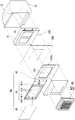
- It is an exploded explanatory view which shows the holding structure of the heat exchanger of the outside air conditioner shown in FIG. 3 from the side.
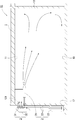
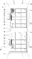
- It is explanatory drawing which shows the operation of the ventilation air-conditioning structure shown in FIG.
- Embodiments of the present invention will be described in more detail with reference to FIGS. 1 to 12. The following description will be given in the order of [First Embodiment], [Modified Example 1], [Second Embodiment], and [Modified Example 2].
- the reference numerals in each drawing are attached within a range that reduces complexity and facilitates understanding, and a plurality of equivalents having the same reference numerals may be assigned only a part thereof. ..
- the above-mentioned “room structure” is simply referred to as “room”.
- the above-mentioned “wall part” is referred to as “first wall part”
- the above-mentioned “wall part facing the outer wall part” is referred to as “second wall part”.
- the other wall portions located between the and the second wall portion are referred to as “third wall portion” and “fourth wall portion”, respectively.
- the above-mentioned "first ventilation port” is referred to as an "air supply port”
- the above-mentioned “second ventilation port” is referred to as an “exhaust port”.
- the above-mentioned "first opening” is referred to as an “introduction port”
- the above-mentioned “second opening” is referred to as a "outlet port”.
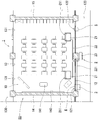
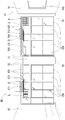
- the ventilation / air conditioning structure R1 includes a room 1, an air conditioner 2, an outside air conditioner 3, an air filter device 4, and an exhaust device 5. Each part will be described in detail below.
- the room 1 has a floor portion 10, a ceiling portion 11, a first wall portion 12, a second wall portion 13, a third wall portion 14, and a fourth wall portion 15.
- the room 1 is a classroom, and the teaching platform 141 is installed in the vicinity of the third wall portion 14.
- the ceiling portion 11 is arranged above the floor portion 10. Since the room 1 is a classroom in the present embodiment, the space between the floor 10 and the ceiling 11 is provided at a height (at least 3 meters) based on Article 21, Paragraph 2 of the Building Standards Act Enforcement Ordinance. ing.
- the first wall portion 12 constitutes the outer wall of the building between the ceiling portion 11 and the floor portion 10. Since the room 1 is a classroom in the present embodiment, in a general school structure, it is obligatory to form a wall facing the outside of the playground or the like from the viewpoint of daylighting or the like, and the first wall portion 12 is Corresponds to the wall.
- the first wall portion 12 has a pillar (reference numeral omitted) in the center, and glass windows (reference numeral omitted) having a height from the floor portion 10 to the ceiling portion 11 are arranged on both sides of the pillar portion. ..
- This glass window is a part of a normal sliding window 124 provided below and a column window (high window) provided above, sandwiching a lintel-shaped upper horizontal member that is about 2 meters high. It has 125 parts (see FIG. 2).
- the room 1 has a structure having a veranda 123 outside the first wall portion 12, and an outdoor unit 23 described later is installed on the veranda 123.
- the mode is not limited to this, and for example, the outdoor unit 23 may be mounted via a pedestal or the like provided on the outer surface of the first wall portion 12.
- the first wall portion 12 is provided with an air supply port 121 and an exhaust port 122.
- the air supply port 121 is provided in the gap between the column windows (that is, the area near the third wall portion) closest to the third wall portion 14, and the exhaust port 122 is the first.
- the window between the columns closest to the 4 wall portion 15 (that is, the area near the 4 wall portion) is removed and provided in the gap.
- the present invention is not limited to the above-described embodiment, and various building structures may be used, for example, an air supply port or an exhaust port having a hole formed in the wall surface.
- the second wall portion 13 is arranged in the opposite direction of the first wall portion 12 with the floor portion 10 and the ceiling portion 11 sandwiched between them. Since the room 1 is a classroom in the present embodiment, in a general school structure, the wall facing the outer wall divides the corridor 130 and the classroom, and an entrance / exit 131 to the corridor 130 is formed. The second wall portion 13 corresponds to the wall.
- the third wall portion 14 is a wall arranged so as to close between the side ends of either one of the first wall portion 12 and the second wall portion 13.
- the third wall portion 14 is provided with a teaching platform 141 along the third wall portion 14, and is provided with a display device 142 such as a blackboard.
- the fourth wall portion 15 is arranged in the direction opposite to the third wall portion 14 with the floor portion 10 and the ceiling portion 11 sandwiched between them, and is located on the other side between the first wall portion 12 and the second wall portion 13. It is a wall provided to close the edges.
- the room 1 which is a classroom has the above-mentioned structure, but is not limited to this.
- the fourth wall when the room is at the edge of the building (so-called corner room), the fourth wall also has a window. It can be an outer wall to have. Further, an entrance to the corridor may be provided on the fourth wall.
- the air conditioner 2 is a so-called package air conditioner having an indoor unit 21 and an outdoor unit 23 connected to the indoor unit 21 via a refrigerant pipe 22.
- the indoor unit 21 is arranged in the vicinity of the first wall portion 12 in the room 1, the intake port 212 is arranged so as to face the floor portion 10, and the air outlet 211 is arranged toward the second wall portion 13 direction.
- the refrigerant pipe 22 is branched between the indoor unit 21 and the outdoor unit 23, and can supply the refrigerant distributed by the heat exchanger 31 of the outside air conditioner 3.
- the indoor unit 21 is a ceiling-mounted packaged air conditioner, but the present invention is not limited to this, and may be, for example, a ceiling cassette type, a wall-mounted type, a floor-standing type, or the like. It may be a room air conditioner.
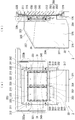
- the outside air conditioner 3 is arranged outside the room 1 of the first wall portion 12, and has a heat exchanger 31 and a casing 32 for storing the heat exchanger 31. As shown in FIGS. 3 to 4, the outside air conditioner 3 is installed on the outer surface of the first wall portion 12 so as to align the outlet 322 with the air supply port 121 of the first wall portion 12. Each part of the outside air conditioner 3 will be described in detail below with reference to FIGS. 1 to 4 (particularly FIG. 3).
- the heat exchanger 31 is incorporated in the refrigerant circuit of the air conditioner 2 via a branch pipe 221 (see FIG. 2) branched from the refrigerant pipe 22, and can exchange heat with the outside air introduced in the casing 32. It is a thing.
- the two heat exchangers 31 are provided side by side in the left-right direction so as not to overlap each other in the ventilation direction (see FIG. 3A).
- Each heat exchanger 31 has a separate system for the refrigerant flow path, and the refrigerant is supplied to each system by the re-branch pipes 222a and 222b that further branch the branch pipe 221.
- Each heat exchanger 31 is a so-called fin tube composed of a heat transfer tube (not shown) having a meandering shape in which straight portions and folded portions are alternately continuous, and a plurality of fins (not shown) intersecting in the radial direction of the heat transfer tube. It is an expression.
- Each heat exchanger 31 is provided so that the axial direction of each stage of the straight portion of the heat transfer tube and the vertical direction of the installed outside air harmonizer 3 are orthogonal to each other, whereby the lubricating oil component contained in the refrigerant is removed. It suppresses the accumulation in the folded part.
- Each heat exchanger 31 has a first inlet / outlet pipe 311 and a second inlet / outlet pipe 313 connected to a heat transfer tube, and a first joint portion 312 is at the tip of the first inlet / outlet pipe 311 and the tip of the second inlet / outlet pipe 313. Is provided with a second joint portion 314, respectively.
- the first joint portion 312 and the second joint portion 314 can be connected to and disconnected from the refrigerant pipes (re-branch pipes 222a and 222b) connected to the air conditioner 2.
- the first inlet / outlet pipe 311 and the first joint portion 312 of one heat exchanger 31 are on one side surface of the casing 32 (FIG. 3 (FIG. 3).
- the re-branch pipe 222a which is arranged on the right side) in a) and is connected, is arranged so that it can be easily handled.
- the second inlet / outlet pipe 313 and the second joint portion 314 of the other heat exchanger 31 are arranged and connected to the other side surface (left side in FIG. 3A) of the casing 32 of the rebranch pipe 222b. It is designed to be easy to handle.
- Each heat exchanger 31 is provided in a size that covers each of the outlets 322, which will be described later.
- Each of the heat exchangers 31 has a heat exchanger holding structure portion 340 and a partition portion 315, which will be described later, at a predetermined distance from the outlet port 322 and covers the outlet port 322 when viewed from the front of the machine body. It is held.
- a compartment 315 is provided between the heat exchanger 31 and the base portion 330, which will be described later.
- the partition portion 315 is a square square frame, and is formed in a manner in which the opening portion of the channel material having a C-shaped cross section is directed toward the inside of the frame, and has a substantially airtight structure. Further, in the compartment 315, the inner shape (mouth edge portion) of the opening portion inside the frame is set to be substantially the same as the outer shape of the heat exchanger 31, and the heat exchanger 31 closes the opening portion. It is attached detachably.
- the partition portion 315 is attached so that the outlet 322 is located in the area inside the frame to partition the inside and outside of the frame, and has a predetermined size between the substrate portion 330 and the attached heat exchanger 31. (See Fig. 3).
- the compartment 315 has a drain hole 317 formed in a portion in the direction of the water receiving portion 350, which will be described later at the time of attachment (see FIG. 3A), from the heat exchanger 31 into the compartment 315.
- the dropped dew condensation water can be discharged to the water receiving portion 350.
- screw holes (not shown) are formed on the left and right side surfaces at the time of attachment, and the hooking screws 316 are screwed into the screw holes.
- the screw holes and the hooking screws 316 are provided with positions and numbers corresponding to the hooking cutouts 341 of the heat exchanger holding structure portion 340 described later, and the hooking screws 316 are provided in the hooking cutouts 341.
- the compartment 315 (and the attached heat exchanger 31) can be detachably attached to the heat exchanger holding structure portion 340 (see FIG. 4).
- the compartment 315 and the heat exchanger holding structure 340 are separate bodies, but the present invention is not limited to this, and for example, the compartment and the heat exchanger holding structure are integrated.
- the heat exchanger holding portion may be formed in a partition shape along the inner edge of the peripheral wall of the outlet, and may have a structure in which the outlet and the heat exchanger are held so as to overlap each other. Then, according to this heat exchanger holding portion, the region from the heat exchanger to the outlet can be partitioned by the partition wall portion, and the harmonized outside air can be prevented from diffusing in a direction other than the outlet. By holding the heat exchangers so as to overlap each other, the harmonized outside air that has passed through the heat exchangers reaches the outlet in the shortest distance.
- the casing 32 is mainly made of a metal material, and is composed of a base 323 that is the back side of the machine body and a peripheral wall body 320 that is the front side of the machine body when installed along the outer surface of the first wall portion 12.
- the structure is such that the peripheral wall body 320 can be attached to and detached from the substrate 323.
- a screw insertion hole (not shown) formed in the base 323 and a screw insertion hole 332 (described later) formed in the flange portion 326 of the peripheral wall body 320 are communicated with each other to form a bolt (not shown). ) Is inserted and fastened.
- other known detachable structures for example, a locking structure due to unevenness
- each part of the casing 32 will be described in detail.
- the substrate 323 has a substrate portion 330, a heat exchanger holding structure portion 340, and a water receiving portion 350 (see FIGS. 3 and 4).
- the substrate portion 330 has a shape along the outer surface of the first wall portion 12, and has a rectangular plate shape slightly smaller than the outer shape of the mounting frame body 328 described later.
- the substrate portion 330 is formed with two rectangular openings arranged side by side in the left-right direction with a partition interposed therebetween, and each opening serves as an outlet 322.
- the size of the outer shape of each outlet 322 combined is substantially the same as the outer shape of the air supply port 121 of the first wall portion 12.
- the substrate portion 330 penetrates in the plate thickness direction, and a fixing member (hereinafter referred to as "screw or the like") such as a bolt, a screw, a nail, a pin or an anchor bolt used for installation on the first wall portion 12 can be inserted.
- a plurality of insertion holes 332 such as screws are formed.
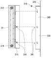
- the heat exchanger holding structure portion 340 is provided for each outlet port 322, and the heat exchanger is provided in such a manner that the longitudinal direction of the fins of the heat exchanger 31 and the direction from the introduction port 321 toward the outlet port 322 substantially coincide with each other. It is a structure that holds 31.
- the heat exchanger holding structure unit 340 holds the heat exchanger 31 in a manner in which the longitudinal direction of the fins of the heat exchanger 31 substantially coincides with the vertical direction of the airframe in the installed state of the airframe.
- Each of the heat exchanger holding structure portions 340 is a pair of plate bodies provided along the outer edges on both the left and right sides of the outlet 322, and each is in the direction from the substrate portion 330 to the peripheral wall body 320 (FIG. 3A). It is a shape that stands up in the front direction) (see FIG. 4).
- each hooking notch 341 has a hook-like shape that descends from the tip of the plate body (in other words, the front side of the machine body) toward the lower side of the machine body (see FIG. 4).
- the heat exchanger holding structure portion 340 hooks the neck portion of the hooking screw 316 of the compartmentalized portion 315 described above to the hooking notch 341 to attach the compartmentalized portion 315 (and the heat exchanger 31 attached to the compartmentalized portion 315). ) Can be locked. According to this locking mode, the heat exchanger holding structure portion 340 holds the partition portion 315 including the heat exchanger 31 to heat the inner surfaces of the front wall portion 324, the substrate portion 330, and the side plate portion 326. A predetermined interval can be provided between the exchanger 31 and the exchanger 31.
- the water receiving portion 350 is arranged at a location between the heat exchanger 31 and the introduction port 321 and has a structure having a water receiving support portion 351, a drain pan 352, and a drainage path 353.
- the water receiving support portion 351 rises from the substrate portion 330 toward the front side of the machine body, and is provided so as to face the machine body in the left-right direction at a distance slightly longer than the length in the longitudinal direction of the drain pan 352.
- the water receiving support portion 351 has a bottomed receiving shape (a shape having a bottom surface and three side surfaces) in which the water receiving support portion 351 is open in the opposite direction and the upward direction, and the drain pan 352 can be detachably supported and at the time of attachment.
- the drain pan 352 has a shape that does not easily come off.
- the drain pan 352 has a bottom surface and four side surfaces rising from the bottom surface, and has a bottomed box shape having an opening that opens upward (in other words, the side facing the heat exchanger 31) at the time of attachment.
- the drain pan 352 has an opening slightly wider than the end surface below the heat exchanger 31, and the side surface of the drain pan 352 has a shape in which the width gradually narrows toward the bottom.
- the lateral length of the drain pan 352 is formed to be longer than the total length of the lateral widths of the heat exchangers 31, and the condensed water dripping from the heat exchangers 31 is not leaked. I am trying to receive it.
- a sheet-shaped heat insulating material (not shown) is attached to the outer surface of the drain pan 352.
- the drainage path 353 is a pipe body whose one end side communicates with the drain hole 354 formed in the center of the inner bottom surface of the drain pan 352 and the other end side is led out to the outside of the machine, and the inside of the dew condensation water or the like dropped into the drain pan 352.
- the accumulated water can be drained to the outside of the machine.
- the drainage path 353 does not limit the mode of the tip portion thereof, and may be connected to, for example, a drain pipe of an air conditioner, a rainwater or a miscellaneous drainage system, or simply open to the outside. Good.
- the peripheral wall body 320 has a substantially square box shape, and has a front wall portion 324 provided at a position facing the substrate portion 330 in a state of attachment to the substrate 323 and an outer edge portion of the front wall portion 324 toward the back.
- a side wall portion 325 having a structure in which the side surfaces of the three extended sides (upper and horizontal directions) are integrated, a flange portion 326 having a predetermined width that is bent at a substantially right angle from the side wall portion 325 and extending outward, and a front surface. It has a wall portion 324 and a heat insulating structure portion 327 provided on the inner surface of the side wall portion 325.
- the portion where the side wall portion 325 is not formed serves as the introduction port 321.
- the introduction port 321 has a net-like or lattice-like shape that covers the opening portion, and a filter member (not shown) for preventing the invasion of birds, small animals, and the like is attached. Then, the peripheral wall body 320 attaches the base 323 on which the outlet 322 and the like are formed to the portion facing the front wall portion 324 (that is, the open back portion).
- the side wall portion 325 has a bent portion in the region between the substrate portion 330 and the front wall portion 324 at the upper surface portion, and is composed of two surfaces that incline downward in the front wall portion 324 direction. As a result, dust is less likely to accumulate on the upper surface of the side wall portion 325, and the load applied to the front wall portion 324 due to the strong wind from the front direction of the machine body is easily evacuated.
- the outer surface of the front wall portion 324 and the side wall portion 325 is formed of a water-repellent material or shape, or is coated with a water-repellent paint.
- the heat insulating structure portion 327 has a structure in which a sheet-shaped heat insulating member having an adhesive surface and a heat reflecting surface is attached to the inner surfaces of the front wall portion 324 and the side wall portion 325 with a heat insulating layer sandwiched between them.
- the heat insulating structure portion is not limited to the above-described embodiment.
- the front wall portion and the side wall portion are formed of a material or shape having heat insulating properties and heat reflectivity, or the heat insulating structure is defined as heat insulating. It may be processed to have heat reflectivity.
- the heat insulating structure is composed of an outer surface plate which is an outer surface of the airframe, an inner surface plate which is an inner surface of the airframe, and a heat insulating material arranged between the inner surface plate and the outer surface plate (or no heat insulating material is used between the plates). It may have a structure (to make it extremely low pressure).
- the mounting frame 328 has a rectangular plate shape, and an opening 329 is formed in the center.
- the mounting frame body 328 is used by being fitted into the window frame of the above-mentioned column window 125, and the outside air harmonizer 3 is mounted by aligning the positions of the opening 329 and the outlet 322 (see FIG. 10).
- Air filter device 4 covers the air supply port 121 so as to be ventilated, and is provided along the first wall portion 12 inside the room 1.
- the air filter device 4 is a glass having a filter sheet.
- the exhaust device 5 is arranged at the exhaust port 122, and is a so-called ventilation fan in the present embodiment. Ventilation
- the ventilation in the air-conditioning structure R1 is a type 3 ventilation (exhaust uses mechanical ventilation and natural ventilation for air supply) by an outside air harmonizer 3 which is a natural air supply means and an exhaust device 5 which is a forced exhaust means. It has become.
- the air outlet 211 of the indoor unit 21 of the air conditioner 2 is directed toward the second wall portion 13, the flow of the conditioned air blown out from the indoor unit 21 by the fresh outside air entering from the air supply port 121.
- the air that hits the second wall 13 and then hits the second wall 13 is a mixture of the outside air and the conditioned air, and diffuses in the vertical and horizontal directions of the second wall 13 to enter the room 1. It circulates and can mix the outside air with the air in the room 1 (see FIG. 5). As a result, it is possible to suppress the bias of CO 2 equal concentration in various places in the room.
- the indoor unit 21 is arranged near the air supply port 121 and on the ceiling, and the fresh outside air entering from the air supply port 121 is a horizontal laminar flow during the cooling operation and an upward flow during the heating operation. It is easy to get on the flow of harmonious air. Further, the heat of the harmonized outside air by the outside air harmonizer 3 can be taken into the indoor unit 21 before much heat is lost.
- outside air conditioner 3 Since the outside air conditioner 3 is arranged on the outdoor side of the first wall portion 12, it is easier to install it in either a new building or an existing building as compared with the one installed under the ceiling or under the floor. In addition, maintenance is easy because the airframe after installation is not covered by the ceiling, floor, or the like.
- the outside air harmonizer 3 can harmonize the outside air by the heat exchanger 31 until the outside air passes through the air supply port 121. Further, in the present embodiment, since the outside air conditioner 3 has two heat exchangers 31 arranged side by side, a sufficient amount of outside air harmonization and harmonized outside air supply even in a large space such as a classroom. It can be performed.
- the outside air conditioner 3 By performing the outside air conditioning by the outside air conditioner 3, the extreme temperature difference between the entering harmonized outside air and the air in the room is eliminated, and the temperature difference from the target temperature of the air conditioner 2 can be reduced. .. As a result, in the air conditioner 2, the rise time until the set target temperature is reached is shortened, and the operating load of the air conditioner 2 can be reduced.
- the outside air conditioner 3 has a structure that is interlocked with the operation of the air conditioner 2 (the outside air conditioner 3 itself does not use electric power) because it is incorporated in the refrigerant circuit of the air conditioner 2. Therefore, there is no need for electric power and a unique refrigerant for operating the aircraft. That is, the above-mentioned air conditioner and the outside air conditioner can cooperate with each other to contribute to energy saving.
- the outside air conditioner 3 can prevent the heat exchanger 31 from being exposed in the outdoor environment and can protect the heat exchanger 31 from deformation and dirt adhesion due to an external force. That is, since the weather resistance and durability are improved, the product life can be extended. Further, since the heat exchanger 31 is a fin tube type, the heat exchange efficiency is good, and the passing outside air can be efficiently heated or cooled. Further, since the fin tube type heat exchanger 31 is small and lightweight, the entire body of the outside air conditioner 3 can be reduced in size and weight. As a result, the load applied to the installed first wall surface 12 can be reduced.
- the peripheral wall body 320 divides the inside and outside of the machine body to form a flow path for the outside air, and prevents the harmonized outside air heated by the heat exchanger 31 from mixing with the outside air, or the harmonized outside air is outside the machine. It can be prevented from spreading to. Further, the heat insulating structure portion 327 can suppress or reduce that the outside air and the harmonized outside air that have entered the casing 32 are affected by the heat caused by the environment outside the machine. For example, even if the outer surface of the peripheral wall body 320 of the outside air harmonizing machine 3 becomes hot due to direct sunlight in the summer or low temperature due to wind and snow in the winter, these heats are generated inside the machine (for example, the peripheral wall body 320). Direct transmission to the inner surface) is suppressed or reduced.
- the introduction port 321 can introduce outside air and make it difficult for wind and rain to enter the casing 32. Further, the outlet 322 can reach the air supply port without diffusing the harmonized outside air and can be led out into the room. Furthermore, the heat exchanger holding unit 340 prevents the harmonized outside air that has passed through the heat exchanger 31 from diffusing in a direction other than the outlet 122, and reaches the outlet at the shortest distance.
- the air filter device 4 can prevent dust and insects contained in the harmonized outside air from entering the room.
- the exhaust device 5 can exhaust the air in the room 1 and can reduce the CO 2 equal concentration in the room.
- the ventilation and air conditioning structure R1 it is possible to provide a comfortable space as a room, especially a classroom, as described above.
- the ventilation / air conditioning structure R1 contributes to energy saving by suppressing the amount of power consumption during operation, and contributes to society as an environmental load reduction technology.
- the air conditioner installed in each room can be used as a heat source, which means that the heat source can be secured in each room, and the ventilation / air conditioning in each room is possible. It means that there is. Therefore, fine-tuned operation is possible, such as not performing ventilation and air conditioning in an unused room, which contributes to energy saving and reduction of running costs.
- Ventilation and air conditioning method Ventilation The air conditioning method will be described. Ventilation The air conditioning method has a first step and a second step.
- the heat exchanger 31 described above is used to heat or cool the outside air introduced into the casing 32 of the outside air conditioner 3.
- the harmonious outside air harmonious with the outside air by the above-mentioned outside air harmonizing machine 3 is introduced into the room 1 through the air supply port 121 communicating with the outlet 322, and the indoor unit 21 is in the direction of the second wall portion 13.
- the air in the room 1 and the introduced harmonious outside air are convected and mixed, and exhausted from the exhaust port 122.
- the outside air enters from the introduction port 321 of the outside air harmonizing machine 3.
- it is heated or cooled by the heat exchanger 31 in the casing 32 to become harmonious outside air.
- the heat exchanger 31 of the outside air conditioner 3 receives the supply of the refrigerant through the refrigerant circuit of the air conditioner 2 and exchanges heat of the outside air.
- the harmonious outside air enters the room through the outlet 322 of the outside air harmonizer 3.
- the harmonized outside air reaches the room 1 without diffusing through the outlet 322 that communicates with the air supply port 121.
- the harmonized outside air that has reached the room is convected with the air blown in the direction of the second wall portion 13 performed by the indoor unit 21 and mixed with the air in the room 1.
- the mixed air hits the second wall portion 13 on the flow of the harmonized air blown out from the indoor unit 21, diffuses in the vertical and horizontal directions of the second wall portion 13, and convects in the room 1 (inside the room). (Circulation) and suppress the bias of CO 2 equal concentration in various places in the room 1. Then, the air circulated in the room 1 goes out to the outside (exhaust) through the exhaust port 122, and the CO 2 equal concentration in the room 1 decreases. It should be noted that the fresh outside air immediately after entering from the air supply port 121 is unlikely to be immediately discharged from the exhaust port 122 at a distant position.
- classroom A and classroom B are adjacent classrooms of the same school and have substantially the same structure in size and shape. Further, in the classroom A and the classroom B, the same number of air conditioners 2 of the same model (one air conditioner having two indoor units and one outdoor unit) and the same layout are arranged.
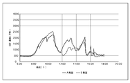
- FIG. 6 shows the results of the preliminary evaluation conducted on January 9, 2019, before the ventilation structures were installed in the A and B classrooms.
- regular classes were held in both classrooms A and B, and 25 students and teachers used the classrooms.
- windows and the like were closed and the air conditioner was operated during the lesson.
- a CO 2 monitor was placed in the center of the 4th wall, and measurements were taken every 5 minutes.
- the sharp decrease in carbon dioxide concentration during the day is due to the break time and ventilation according to the instruction of the teacher, and the rapid decrease in carbon dioxide concentration in the evening is due to the student leaving school.
- classroom A is composed of the above-mentioned ventilation and air conditioning structure R1.
- classroom B is equipped with the same exhaust device (ventilation fan) as classroom A at the exhaust port, but it is a mere ventilation structure in which only the garage is arranged at the air supply port and the outside air conditioner 3 is not provided. is there.
- FIG. 7 shows the results of measurements performed on January 31, 2019, after the construction work in which the A classroom has a ventilation and air conditioning structure R1 and the B classroom has a ventilation structure.
- regular classes were held in both classrooms A and B, and 25 students and teachers used the classrooms.
- windows and the like were closed during the lesson, an air conditioner was used, and the exhaust system was used "strongly".
- the maximum carbon dioxide concentration in both classrooms A and B was about 1300 PPM.
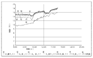
- FIG. 8 shows the results of measurements performed on February 3, 2019, after the installation of the ventilation air conditioning structure or ventilation system. The same day was a holiday, and both classrooms A and B used classrooms where students and teachers were absent. In both classrooms A and B, the windows and the like were closed and the air conditioner 2 was used. In addition, the exhaust system was used in "strong" in both classroom A and classroom B.
- the graph shown in FIG. 8 shows the temperature changes in the classroom A and the classroom B, and the vicinity of the second wall portion 13 in the classroom A (circle a shown in FIG. 8) and the vicinity of the fourth wall portion 15 in the classroom A (FIG. 8).
- the temperature changes measured in the vicinity of the fourth wall portion (circle e shown in FIG. 8) in the classroom B and in the vicinity of the third wall portion (circle f shown in FIG. 8) in the classroom B are shown.
- the second wall portion 13 is the central portion
- the third wall portion 14 is near the air supply port 121
- the fourth wall portion 15 is the exhaust port 122.
- temperature measuring instruments were placed at a height of 1.1 meters from the floor (the height of the student's head or chest when seated), and measurements were taken every 5 minutes.
- the difference between the temperature measured in the vicinity of the second wall portion 13 and the vicinity of the fourth wall portion 15 in the classroom A and the temperature measured in the vicinity of the third wall portion 14 is about 1 degree, and A. It can be said that there is no large temperature difference in the classroom.
- the measured temperature near the third wall in the B classroom is the lowest among the measured temperatures in the room, and the measured temperature near the third wall in the B classroom is the measured temperature near the third wall 14 in the A classroom. About 1 degree lower than. Then, from the start of the experiment (6:00) to the elapse of a predetermined time (9:40), the average temperature of each part in the A classroom is higher than the average temperature of each part in the A classroom.
- the air conditioner 2 starts up quickly, and the average temperature of each part in the A classroom is small. According to this environment, the discomfort caused by the large temperature difference depending on the seat of the person in the room (hereinafter referred to as "the person in the room”) can be reduced, which can contribute to the improvement of the comfort of many people in the room. it can.
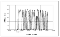
- FIG. 9 shows the results of measurements performed on February 3, 2019, after the installation of the ventilation structure.
- the same day was a holiday, and both classrooms A and B used classrooms where students and teachers were absent.
- both classrooms A and B windows and the like were closed and an air conditioner was used.
- the exhaust system was used in "strong" in both classroom A and classroom B.
- the measurement time is from 9:20 to 12:10.
- the target temperature of the air conditioner was set to 22 degrees
- Class B the target temperature of the air conditioner was set to 24 degrees.
- the PMV Predicted Mean Vote "Predicted Mean Voter" value and room temperature at a height of 1.1 meters from the floor became almost the same.
- the A classroom having the ventilation air conditioning structure R1 can suppress the power consumption of the air conditioner 2, and the harmonized air blown from the air conditioner 2 can be suppressed.
- the A classroom having the ventilation air conditioning structure R1 can suppress the power consumption of the air conditioner 2, and the harmonized air blown from the air conditioner 2 can be suppressed.
- the exhaust device 5 is a ventilation fan, but it may be a natural exhaust means such as a glass.
- an outside air conditioner using the above-mentioned outside air conditioner 3 which is a natural ventilation means
- the exhaust port is garaged (natural ventilation).
- It is a natural ventilation system in which an exhaust device (means) is arranged.
- the ventilation / air-conditioning structure of the first modification since there is no operating fan or the like, power consumption related to ventilation is not generated, and the structure does not require fan maintenance. It is also very quiet.
- the ventilation / air conditioning structure R2 shown in FIG. 10 is another embodiment (second embodiment) of the ventilation / air conditioning structure R1. Since the ventilation / air conditioning structure R2 is the same as the ventilation / air conditioning structure R1 except for the parts described later, only the differences will be described, the common parts will be given the same reference numerals, and the description of the structure will be omitted. The description of the action and effect will also be omitted.
- the ventilation / air conditioning structure R2 has an air filter device 4a combined with an air filter unit 40 and an air supply fan unit 43 on the indoor side of the air supply port 121 (see FIGS. 10 and 11A). That is, the ventilation in the ventilation air-conditioning structure R2 is a type 1 ventilation (both supply and exhaust use mechanical ventilation) method by the air supply fan unit 43 which is a forced air supply means and the exhaust device 5 which is a forced exhaust means. It has become.
- the air filter unit 40 is arranged between the substrate unit 330 and the fan body mounting frame 432 described later, and is composed of a ventilation port filter sheet 401, a holding body 41, and a support frame body 42.
- the holding body 41 has a rectangular frame-shaped frame portion 411 arranged on the periphery, a contact portion 412 provided inside the frame portion 411 and thinner than the frame portion 411, and each corner of the contact portion 412. It has a spring-shaped seat locking piece 413 (4 in total) that is provided near the portion and can rotate around a mounting shaft (reference numeral omitted) provided on one end side, and is rectangular in the center of the contact portion 412. It is a structure in which the opening 414 of the above is formed.
- a net body covering the opening is stretched in the opening 414 (not shown). According to this net body, when the air volume of the harmonized outside air is large, the ventilation port filter sheet 401 can be supported so as to bend toward the indoor side and not easily fall off. Further, instead of the net body, a cross-shaped or lattice-shaped frame body may be used.
- the support frame body 42 has a rectangular frame shape in which a rectangular opening 421 is formed from the central portion to the upper portion, and an internal space in which the holding body 41 is accommodated is formed around the opening 421.
- the support frame body 42 is formed with insertion ports 422a and 422b communicating from the side of the internal space, and the insertion ports 422a and 422b are sized so that the holding body 41 can be taken in and out from any of them.
- the opening 414 of the holding body 41 and the opening 421 of the supporting frame body 42 have substantially the same size, and are exactly overlapped with the holding body 41 in the supporting frame body 42.
- the air supply fan portion 43 is composed of a fan main body 431 and a fan main body mounting frame 432 in which the front side and the back side are open and the periphery is flange-shaped, and the fan main body 431 can be attached to the central opening. Will be done.
- the ventilation method in the room 1 can be performed by the first-class ventilation, so that stable ventilation can be ensured.
- the air supply fan unit 43 is convenient because maintenance work such as cleaning the fan can be performed in the room 1. Similarly, since the air filter unit 40 can also perform operations such as replacement of the ventilation port filter sheet 401 in the room 1, maintainability is further improved and convenience is good.
- the ventilation port filter sheet 401 can stop the ingress of dust and the like contained in the passing harmony outside air. Further, since the ventilation port filter sheet 401 can be replaced, it can be replaced each time so as not to cause clogging. Furthermore, the ventilation port filter sheet 401 can be easily attached to and detached from the holding body 41, and can be easily performed by the user without any special work, and the operating cost can be suppressed.
- the holding body 41 can be held in a deployed state by locking the edge of the ventilation port filter sheet 401, and can be held detachably.
- the support frame body 42 can support the inserted holding body 41.
- the holding body 41 can be supported so that the ventilation port filter sheet 401 does not shift from the predetermined position and the air not filtered by the ventilation port filter sheet 401 is ventilated. Further, since the holding body 41 can be taken in and out from the side of the support frame body 42, the ventilation port filter sheet 401 can be replaced easily and safely.
- the exhaust device 5 is a ventilation fan, but it may be a natural exhaust means such as a glass.
- an air supply fan portion 43 force ventilation means
- an exhaust device 5a which is a garage (natural ventilation means) is provided at the exhaust port 122.
- It is a type 2 ventilation system (mechanical ventilation is used for air supply and natural ventilation is used for exhaust).
- the ventilation and air conditioning structure R3 not only the air supply fan portion 43 but also the air filter device 4a may be arranged.
- the ventilation / air conditioning structure R3 since there is no fan or the like operating in the exhaust device 5a, power consumption related to exhaust is not generated, and if the room 1 has an airtight structure, the room is higher than the outside air.
- the pressure can be maintained, and the structure can be made suitable for a clean room, a hospital room, or the like.
- the heat exchanger 31 is configured to be housed in the casing 32, but it does not necessarily have to be housed in the casing 32.
- a heat exchanger unit 33 for storing the heat exchanger 31 may be provided, and the heat exchanger unit 33 may be attached to the casing 32.
- the modification 3 (configuration of the heat exchanger unit 33) is inferior to the case where the heat exchanger 31 is stored in the casing 32 in terms of saving space, but the general-purpose casing 33 is used as it is. It can be used and does not need to be processed for storage. Further, even when the storage space cannot be secured in the casing 32, such as a structure in which the casing 32 is provided with a fireproof damper structure, it is possible to deal with it.
- the front and back surfaces (casing 32 side and the mounting frame) of the heat exchanger unit 33 are used to ensure the airtightness of the mounting portion and to suppress air leakage and rainwater leakage. It is preferable to attach a butyl tape (however, it is not limited to the butyl tape as long as the airtightness can be ensured) on the body 328 side).
- the modification 3 (that is, the configuration in which the heat exchanger 31 is stored in the heat exchanger unit 33 as shown in FIG. 11B) is adopted in the method using natural ventilation for the air supply as in the first embodiment. You may.
- the intake port filter sheet 213 containing copper oxide as an antiviral metal component is arranged in front of the intake port 212 of the indoor unit 21. You may.
- the intake port filter sheet 213 can inactivate bacteria and viruses floating in the air sucked from the intake port 212. That is, copper oxide, which is an oxide of copper, can be in a state (radical) having unpaired electrons according to the oxidation number even under normal temperature and pressure where light irradiation and heating are not performed.
- Unpaired electrons of radicals are basically unstable, and it is known that they rob or donate electrons to atoms, molecules, etc. that come into contact with the radicals. Therefore, radicals can denature molecules constituting pollutants such as bacteria and viruses, and can sterilize and inactivate viruses.
- the intake port filter sheet 213 is arranged in front of the intake port 212, when the intake port filter sheet 213 deteriorates, it is possible to visually determine a guideline for replacement and replacement, and the indoor unit 21 can also be replaced. Can be easily performed without disassembling. Further, since most of the impurities in the air, including bacteria and viruses, can be captured by the air intake filter sheet 213, deterioration of the internal filter 215 arranged inside the indoor unit 21 can be prevented. ..
- the antiviral metal component is not limited to the copper oxide described above.
- one of silver oxide, iron oxide, and manganese oxide can be selected.
- copper oxide has the highest antiviral effect.
- the antiviral metal component may be contained not only in the intake port filter sheet 213 described above, but also in the ventilation port filter sheet 401 constituting the air filter unit 40, for example.
- the outside air conditioner 3 in the first and second embodiments and the first to third modifications may have a structure in which the casing 32 is provided with a fire damper.
- the air supply port is closed in the event of a fire, and the spread of the fire can be suppressed.
- the exhaust device 5 and the air supply fan unit 43 in the first and second embodiments and the first to third modifications may have a structure in which a CO 2 sensor is provided and automatically operated. Detecting a CO 2 concentration in the room by CO 2 sensor, upon reaching a certain concentration starts operation, when below a certain concentration than be adapted to stop the operation, CO in the room 2
- the concentration can be controlled, and by not operating when it is unnecessary, it contributes to energy saving and can improve quietness.
- the heat exchangers 31 of the outside air conditioner 3 have separate refrigerant flow paths (parallel), but the present invention is not limited to this, and for example, the outdoor unit. Although the operating load of the refrigerant increases, the refrigerant flow paths may be in the same system (series).
- R1, R2, R3 Ventilation and air conditioning structure 1 room 10 floor 11 ceiling 12 1st wall 121 air supply port 122 exhaust port 123 veranda 124 sliding window 125 column window 13 2nd wall 130 corridor 131 entrance 14 3rd wall Part 141 Teaching platform 142 Display device 15 4th wall part 2 Air exchanger 21 Indoor unit 211 Blower port 212 Intake port 213 Intake port filter sheet 214 Front panel 215 Internal filter 22 Refrigerator piping 221 Branch pipe 222a, 222b Re-branch pipe 23 Outdoor unit 3 Outside air exchanger 31 Heat exchanger 311 1st inlet / outlet pipe 312 1st joint part 313 2nd entrance / exit pipe 314 2nd joint part 315 Section 316 Locking screw 317 Drain hole 32 Casing 320 Peripheral wall body 321 Inlet port 322 Outlet 323 Base 324 Front wall 325 Side wall 326 Flange 327 Insulation structure 328 Mounting frame 329 Opening 330 Board 332 Screw insertion hole 333 Insertion hole 340 Heat exchanger holding structure
Landscapes
- Engineering & Computer Science (AREA)
- Chemical & Material Sciences (AREA)
- Combustion & Propulsion (AREA)
- Mechanical Engineering (AREA)
- General Engineering & Computer Science (AREA)
- Chemical Kinetics & Catalysis (AREA)
- Physics & Mathematics (AREA)
- Thermal Sciences (AREA)
- Central Air Conditioning (AREA)
Abstract
L'invention fournit une structure de ventilation et de conditionnement de l'air qui se révèle facile d'installation et d'entretien y compris sur n'importe quel bâtiment de construction nouvelle ou déjà existant, et qui permet une restriction de la consommation d'énergie d'un appareil de conditionnement d'air par mise en œuvre d'un appareil de conditionnement d'air externe connecté, et la circulation d'un air extérieur de conditionnement d'air à l'intérieur d'une pièce par mise en œuvre d'un écoulement d'air conditionné envoyé par l'appareil de conditionnement d'air. La structure de ventilation et de conditionnement de l'air (R1) de l'invention est équipée : d'une pièce (1) dans laquelle une ouverture d'alimentation en air (121) est formée à proximité d'une troisième partie paroi (14) et une ouverture d'évacuation d'air (122) est formée à proximité d'une quatrième partie paroi (15), qui contient une paroi externe de bâtiment et une première partie paroi (13), et qui possède une partie sol (10) ainsi qu'une quatrième partie paroi (15) ; de l'appareil de conditionnement d'air (2) qui est placé à l'intérieur de la pièce (1), et dans lequel au moins une ouverture d'envoi d'air d'une unité intérieure permet un envoi d'air dans la direction d'une seconde partie paroi (13) ; de l'appareil de conditionnement d'air externe (3) qui est placé à l'extérieur de la pièce (1), et qui possède un échangeur de chaleur (31) intégré à un circuit de réfrigérant de l'appareil de conditionnement d'air (2) par l'intermédiaire d'un tuyau de ramification (221) ramifié à partir d'une conduite de réfrigérant (22), et une enveloppe (32) stockant cet échangeur de chaleur (31) ; et d'une partie dispositif de filtre à air (4) agencée sur l'ouverture d'alimentation en air (121) ainsi que d'un dispositif d'évacuation d'air (5) agencé sur l'ouverture d'évacuation d'air (122).
Priority Applications (2)
| Application Number | Priority Date | Filing Date | Title |
|---|---|---|---|
| JP2021532692A JP7088517B2 (ja) | 2019-07-18 | 2020-05-11 | 換気空調構造、および、換気空調方法 |
| US17/414,162 US12173912B2 (en) | 2019-07-18 | 2020-05-11 | Ventilation and air-conditioning structure and ventilation and air-conditioning method |
Applications Claiming Priority (2)
| Application Number | Priority Date | Filing Date | Title |
|---|---|---|---|
| JP2019-132713 | 2019-07-18 | ||
| JP2019132713A JP6765144B1 (ja) | 2019-07-18 | 2019-07-18 | 換気空調構造 |
Publications (1)
| Publication Number | Publication Date |
|---|---|
| WO2021009999A1 true WO2021009999A1 (fr) | 2021-01-21 |
Family
ID=72706622
Family Applications (2)
| Application Number | Title | Priority Date | Filing Date |
|---|---|---|---|
| PCT/JP2019/038578 Ceased WO2021009934A1 (fr) | 2019-07-18 | 2019-09-30 | Structure de ventilation et de conditionnement de l'air, et procédé de ventilation et de conditionnement de l'air |
| PCT/JP2020/018782 Ceased WO2021009999A1 (fr) | 2019-07-18 | 2020-05-11 | Structure de ventilation et de conditionnement de l'air, et procédé de ventilation et de conditionnement de l'air |
Family Applications Before (1)
| Application Number | Title | Priority Date | Filing Date |
|---|---|---|---|
| PCT/JP2019/038578 Ceased WO2021009934A1 (fr) | 2019-07-18 | 2019-09-30 | Structure de ventilation et de conditionnement de l'air, et procédé de ventilation et de conditionnement de l'air |
Country Status (6)
| Country | Link |
|---|---|
| US (1) | US12173912B2 (fr) |
| JP (2) | JP6765144B1 (fr) |
| KR (1) | KR102424865B1 (fr) |
| MY (1) | MY204079A (fr) |
| TW (1) | TWI755637B (fr) |
| WO (2) | WO2021009934A1 (fr) |
Families Citing this family (5)
| Publication number | Priority date | Publication date | Assignee | Title |
|---|---|---|---|---|
| US12305886B2 (en) * | 2020-12-14 | 2025-05-20 | Rheem Manufacturing Company | Heating systems with unhoused centrifugal fan and wraparound heat exchanger |
| WO2021093906A2 (fr) * | 2021-03-08 | 2021-05-20 | 郑州航空工业管理学院 | Système de contrôle de l'opinion publique d'un réseau d'informations du gouvernement |
| CN113932308A (zh) * | 2021-11-09 | 2022-01-14 | 安徽南国机电科技发展有限公司 | 一种空调换新风装置及其控制方法 |
| CN117387156B (zh) * | 2023-09-28 | 2024-05-10 | 无锡维科通风机械有限公司 | 半密闭吊顶热回收通风系统 |
| CN121232924B (zh) * | 2025-12-02 | 2026-03-06 | 四川金叶生物防治有限公司 | 一种面向立体烟垛的自适应气体环境调控方法 |
Citations (13)
| Publication number | Priority date | Publication date | Assignee | Title |
|---|---|---|---|---|
| JPS6219551U (fr) * | 1985-07-22 | 1987-02-05 | ||
| JPS647466B2 (fr) * | 1980-09-11 | 1989-02-08 | Meishin Denki Kk | |
| JPH05203184A (ja) * | 1992-01-23 | 1993-08-10 | Matsushita Electric Ind Co Ltd | 空気調和機 |
| JP2001012763A (ja) * | 1999-07-01 | 2001-01-19 | Matsushita Electric Ind Co Ltd | 空調換気システム |
| JP2001221453A (ja) * | 2000-02-07 | 2001-08-17 | Sanyo Electric Co Ltd | 空気調和機 |
| WO2007026387A2 (fr) * | 2005-09-01 | 2007-03-08 | NM TECH LTD. - Nanomaterials and Microdevices Technology | Filtres photocatalytiques recouverts de suspensions de dioxyde de titane et d'autres substances et procedes permettant d'obtenir de tels filtres |
| JP2007127289A (ja) * | 2005-11-01 | 2007-05-24 | Matsushita Electric Ind Co Ltd | 空気調和機 |
| KR20090034595A (ko) * | 2007-10-04 | 2009-04-08 | 유충열 | 수중의 부유물질이나 공기 중의 초미립자를 여과하면서살균효능을 갖는 정화필터 |
| JP2010127516A (ja) * | 2008-11-27 | 2010-06-10 | Sharp Corp | 空気調和機 |
| JP2014104376A (ja) * | 2012-11-22 | 2014-06-09 | Nbc Meshtec Inc | 導電性を有する集塵部用抗ウイルス性フィルタ |
| CN206018915U (zh) * | 2016-07-22 | 2017-03-15 | 北京普尔绿色环境科技有限公司 | 教室新风系统 |
| CN206055816U (zh) * | 2016-08-31 | 2017-03-29 | 王魁男 | 一种教学楼空气净化系统 |
| CN208998266U (zh) * | 2018-11-12 | 2019-06-18 | 郭爱香 | 教室用多功能组合式新风设备 |
Family Cites Families (15)
| Publication number | Priority date | Publication date | Assignee | Title |
|---|---|---|---|---|
| JPH0684331B2 (ja) | 1985-07-18 | 1994-10-26 | 日東化成株式会社 | 芳香族置換アルキルカルボン酸化合物の製造法 |
| JPH04174227A (ja) * | 1990-11-02 | 1992-06-22 | Mitsubishi Electric Corp | 空気調和機 |
| JP4294784B2 (ja) | 1999-04-07 | 2009-07-15 | 高砂熱学工業株式会社 | 空調設備および空調方法 |
| JP2002156137A (ja) * | 2000-11-17 | 2002-05-31 | Takasago Thermal Eng Co Ltd | 空調用加湿設備 |
| KR100511979B1 (ko) * | 2003-03-13 | 2005-09-02 | 엘지전자 주식회사 | 덕트형 공기조화기 |
| KR100546658B1 (ko) * | 2003-07-29 | 2006-01-26 | 엘지전자 주식회사 | 공조시스템 |
| TWI379979B (en) * | 2009-11-12 | 2012-12-21 | Ind Tech Res Inst | System and method of two-step cold-media processing |
| JP5447360B2 (ja) * | 2010-12-17 | 2014-03-19 | 三菱電機株式会社 | 空気調和装置の制御方法 |
| TWM418267U (en) * | 2011-04-01 | 2011-12-11 | Sin Wi Ze Corp | Air conditioning heat pump hot water unit featuring automatic switching between two heating sources |
| JP6157593B2 (ja) * | 2013-03-27 | 2017-07-05 | 三菱電機株式会社 | 熱交換器およびこれを用いた冷凍サイクル空調装置 |
| TWI504851B (zh) * | 2013-08-02 | 2015-10-21 | Univ Kun Shan | Separate air conditioner |
| JP2015055434A (ja) * | 2013-09-13 | 2015-03-23 | 株式会社 テスク資材販売 | 空調システム |
| TWI512248B (zh) * | 2013-10-08 | 2015-12-11 | Univ Ishou | 移動分離式空調裝置 |
| JP6358534B2 (ja) * | 2014-04-11 | 2018-07-18 | パナソニックIpマネジメント株式会社 | 一体型空気調和機 |
| JP6407466B1 (ja) * | 2018-04-19 | 2018-10-17 | 株式会社 エコファクトリー | 外気調和機および換気システム |
-
2019
- 2019-07-18 JP JP2019132713A patent/JP6765144B1/ja active Active
- 2019-09-30 WO PCT/JP2019/038578 patent/WO2021009934A1/fr not_active Ceased
- 2019-09-30 KR KR1020207006073A patent/KR102424865B1/ko active Active
- 2019-09-30 MY MYPI2020001318A patent/MY204079A/en unknown
- 2019-10-15 TW TW108137018A patent/TWI755637B/zh active
-
2020
- 2020-05-11 US US17/414,162 patent/US12173912B2/en active Active
- 2020-05-11 WO PCT/JP2020/018782 patent/WO2021009999A1/fr not_active Ceased
- 2020-05-11 JP JP2021532692A patent/JP7088517B2/ja active Active
Patent Citations (13)
| Publication number | Priority date | Publication date | Assignee | Title |
|---|---|---|---|---|
| JPS647466B2 (fr) * | 1980-09-11 | 1989-02-08 | Meishin Denki Kk | |
| JPS6219551U (fr) * | 1985-07-22 | 1987-02-05 | ||
| JPH05203184A (ja) * | 1992-01-23 | 1993-08-10 | Matsushita Electric Ind Co Ltd | 空気調和機 |
| JP2001012763A (ja) * | 1999-07-01 | 2001-01-19 | Matsushita Electric Ind Co Ltd | 空調換気システム |
| JP2001221453A (ja) * | 2000-02-07 | 2001-08-17 | Sanyo Electric Co Ltd | 空気調和機 |
| WO2007026387A2 (fr) * | 2005-09-01 | 2007-03-08 | NM TECH LTD. - Nanomaterials and Microdevices Technology | Filtres photocatalytiques recouverts de suspensions de dioxyde de titane et d'autres substances et procedes permettant d'obtenir de tels filtres |
| JP2007127289A (ja) * | 2005-11-01 | 2007-05-24 | Matsushita Electric Ind Co Ltd | 空気調和機 |
| KR20090034595A (ko) * | 2007-10-04 | 2009-04-08 | 유충열 | 수중의 부유물질이나 공기 중의 초미립자를 여과하면서살균효능을 갖는 정화필터 |
| JP2010127516A (ja) * | 2008-11-27 | 2010-06-10 | Sharp Corp | 空気調和機 |
| JP2014104376A (ja) * | 2012-11-22 | 2014-06-09 | Nbc Meshtec Inc | 導電性を有する集塵部用抗ウイルス性フィルタ |
| CN206018915U (zh) * | 2016-07-22 | 2017-03-15 | 北京普尔绿色环境科技有限公司 | 教室新风系统 |
| CN206055816U (zh) * | 2016-08-31 | 2017-03-29 | 王魁男 | 一种教学楼空气净化系统 |
| CN208998266U (zh) * | 2018-11-12 | 2019-06-18 | 郭爱香 | 教室用多功能组合式新风设备 |
Also Published As
| Publication number | Publication date |
|---|---|
| WO2021009934A1 (fr) | 2021-01-21 |
| US20220128245A1 (en) | 2022-04-28 |
| JPWO2021009999A1 (ja) | 2021-10-21 |
| US12173912B2 (en) | 2024-12-24 |
| KR20210010424A (ko) | 2021-01-27 |
| TWI755637B (zh) | 2022-02-21 |
| JP2021018011A (ja) | 2021-02-15 |
| JP6765144B1 (ja) | 2020-10-07 |
| JP7088517B2 (ja) | 2022-06-21 |
| KR102424865B1 (ko) | 2022-07-25 |
| TW202104805A (zh) | 2021-02-01 |
| MY204079A (en) | 2024-08-06 |
Similar Documents
| Publication | Publication Date | Title |
|---|---|---|
| JP7088517B2 (ja) | 換気空調構造、および、換気空調方法 | |
| TWI681153B (zh) | 外氣空調機及換氣系統 | |
| JP6288427B2 (ja) | 大空間の冷房装置 | |
| JP2014156962A (ja) | 空調システム及び空調方法 | |
| Jacobs et al. | Diffuse ceiling ventilation, a new concept for healthy and productive classrooms | |
| ES2971620T3 (es) | Sistema climático de ventilación y método para controlar un sistema climático de ventilación | |
| Osaro et al. | Usefulness of building ventilation | |
| JP2008134032A (ja) | 空気調和システム | |
| JP2015055433A (ja) | 空調システム | |
| JPWO2019111383A1 (ja) | 植物栽培用ハウス | |
| JP2020188788A (ja) | 植物栽培用ハウス | |
| Bhatia | Hvac design for healthcare facilities | |
| JP7845699B2 (ja) | 空調システム | |
| KR102730907B1 (ko) | 환기 시스템 | |
| JP2024151678A (ja) | 可搬型エアコン装置 | |
| KR101480323B1 (ko) | 기존 건축물을 활용한 실내환기 장치. | |
| Bohne | Ventilation Systems | |
| JP2011112341A (ja) | 空気調和装置 | |
| Kurnitski et al. | Mechanical and Mixed-Mode Ventilation in City Centre Buildings | |
| JP4586994B2 (ja) | 建造物の自然換気構造 | |
| US20230059931A1 (en) | Air conditioning appliance having a plenum for make-up air | |
| Pfluger et al. | Minimal invasive ventilation systems with heat recovery for school buildings | |
| KR200384289Y1 (ko) | 벽부착형 열교환 환기장치 | |
| KR20070100434A (ko) | 공조 시스템 | |
| Brown et al. | Natural Ventilation In Northwest Buildings. |
Legal Events
| Date | Code | Title | Description |
|---|---|---|---|
| 121 | Ep: the epo has been informed by wipo that ep was designated in this application |
Ref document number: 20839683 Country of ref document: EP Kind code of ref document: A1 |
|
| ENP | Entry into the national phase |
Ref document number: 2021532692 Country of ref document: JP Kind code of ref document: A |
|
| NENP | Non-entry into the national phase |
Ref country code: DE |
|
| 122 | Ep: pct application non-entry in european phase |
Ref document number: 20839683 Country of ref document: EP Kind code of ref document: A1 |