WO2021010185A1 - Électrode positive et batterie secondaire au lithium-ion - Google Patents
Électrode positive et batterie secondaire au lithium-ion Download PDFInfo
- Publication number
- WO2021010185A1 WO2021010185A1 PCT/JP2020/026133 JP2020026133W WO2021010185A1 WO 2021010185 A1 WO2021010185 A1 WO 2021010185A1 JP 2020026133 W JP2020026133 W JP 2020026133W WO 2021010185 A1 WO2021010185 A1 WO 2021010185A1
- Authority
- WO
- WIPO (PCT)
- Prior art keywords
- positive electrode
- active material
- material layer
- negative electrode
- current collector
- Prior art date
- Legal status (The legal status is an assumption and is not a legal conclusion. Google has not performed a legal analysis and makes no representation as to the accuracy of the status listed.)
- Ceased
Links
Images
Classifications
-
- H—ELECTRICITY
- H01—ELECTRIC ELEMENTS
- H01M—PROCESSES OR MEANS, e.g. BATTERIES, FOR THE DIRECT CONVERSION OF CHEMICAL ENERGY INTO ELECTRICAL ENERGY
- H01M4/00—Electrodes
- H01M4/02—Electrodes composed of, or comprising, active material
- H01M4/13—Electrodes for accumulators with non-aqueous electrolyte, e.g. for lithium-accumulators; Processes of manufacture thereof
-
- Y—GENERAL TAGGING OF NEW TECHNOLOGICAL DEVELOPMENTS; GENERAL TAGGING OF CROSS-SECTIONAL TECHNOLOGIES SPANNING OVER SEVERAL SECTIONS OF THE IPC; TECHNICAL SUBJECTS COVERED BY FORMER USPC CROSS-REFERENCE ART COLLECTIONS [XRACs] AND DIGESTS
- Y02—TECHNOLOGIES OR APPLICATIONS FOR MITIGATION OR ADAPTATION AGAINST CLIMATE CHANGE
- Y02E—REDUCTION OF GREENHOUSE GAS [GHG] EMISSIONS, RELATED TO ENERGY GENERATION, TRANSMISSION OR DISTRIBUTION
- Y02E60/00—Enabling technologies; Technologies with a potential or indirect contribution to GHG emissions mitigation
- Y02E60/10—Energy storage using batteries
Definitions
- the present invention relates to a positive electrode and a lithium ion secondary battery.
- the present application claims priority based on Japanese Patent Application No. 2019-130399 filed in Japan on July 12, 2019, the contents of which are incorporated herein by reference.
- Lithium-ion secondary batteries can achieve high capacity and are widely used from mobile batteries for mobile phones and laptop computers to automobile batteries and large-scale power storage batteries.
- the electrode of the lithium ion secondary battery has a coated portion in which the active material layer is coated on the current collector and an uncoated portion in which the active material layer is not coated, and a connecting portion (tab) for connecting an external terminal to the uncoated portion.
- a cell single tab cell that derives an external terminal from a single connection portion connected to an uncoated portion is a cell (multi-tab cell) that has a connection portion that connects external terminals to a plurality of uncoated portions. It is possible to charge and discharge at a higher current density.
- the present invention has been made in view of the above circumstances, and an object of the present invention is to provide a positive electrode for a lithium ion secondary battery and a lithium ion secondary battery capable of obtaining high cycle characteristics.
- the present inventors have found that the ratio of the sum Ts of the cross-sectional area of the distal end of the connecting portion to the total area Es of the active material layer (Es / Ts) is a 1.90 ⁇ 10 4 ⁇ 2.55 ⁇ 10 5
- Es / Ts the ratio of the sum Ts of the cross-sectional area of the distal end of the connecting portion to the total area Es of the active material layer
- a positive electrode including a current collector and an active material layer.
- the current collector includes a coated portion having an active material layer on at least one surface and a non-coated portion having no active material layer.
- the current collector has one or more connection portions connected to external terminals in the uncoated portion, and the connection portion has a tip in the external terminal lead-out direction.
- a positive electrode characterized in that the total area Es of the active material layer and the total Ts of the cross-sectional area of the tip of the connecting portion satisfy the relationship of the following formula (1).
- a lithium ion secondary battery comprising the positive electrode according to any one of [1] to [4], a negative electrode, a separator separating the positive electrode and the negative electrode, and an electrolyte.
- the present inventors have a ratio (Es / Ts) of the total area Es of the active material layer to the total Ts of the cross-sectional area of the tip of the connecting portion of 1.90 ⁇ 10 4 to. by to 2.55 ⁇ 10 5, increase the heat radiation at the time of discharge, it is possible to provide a lithium ion secondary battery having a positive electrode and its high cycle characteristics can be obtained.
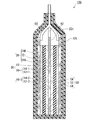
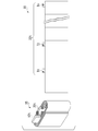
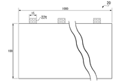
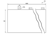
- FIG. 1 It is sectional drawing of the lithium ion secondary battery which concerns on one Embodiment of this invention. It is a schematic diagram of the winding body of the lithium ion secondary battery which concerns on one Embodiment of this invention. It is a schematic diagram of the shape of the positive electrode of the lithium ion secondary battery which concerns on Example 1. FIG. It is a schematic diagram of the shape of the negative electrode of the lithium ion secondary battery which concerns on Example 1. FIG.
- FIG. 1 is a schematic cross-sectional view of the lithium ion secondary battery according to the present embodiment.
- the lithium ion secondary battery 100 shown in FIG. 1 mainly includes a laminate 30, a case 50 that houses the laminate 30 in a sealed state, and a pair of leads 60 and 62 connected to the laminate 30.
- the electrolytic solution is housed in the case 50 together with the laminated body 30.
- the laminated body 30 includes a positive electrode 20, a first negative electrode 10-1, a second negative electrode 10-2, and a separator 18 in the case 50.
- the first negative electrode 10-1 or the second negative electrode 10-2 is arranged so that the positive electrode 20 and the positive electrode 20 face each other with the separator 18 interposed therebetween.
- the number of layers of the positive electrode and the negative electrode may be further increased.
- the laminate 30 of the present invention is a laminate in which the positive electrodes, separators, negative electrodes, etc.
- laminate body A laminated body made of a wound body 35 as shown in FIG. 2 (also referred to as “laminated body B”).
- the positive electrode of the present embodiment includes a current collector and an active material layer.
- the current collector includes a coated portion having an active material layer on at least one surface, and a non-coated portion having no active material layer.
- the current collector has one or more connecting portions (sometimes referred to as “tabs") connected to external terminals in the uncoated portion.
- the connection portion has a tip in the direction of leading out the external terminal.
- the total area Es of the active material layer and the total cross-sectional area Ts of the tip of the connecting portion satisfy the relationship of the following formula (1).
- the ratio (Es / Ts) of the total area Es of the active material layer to the total Ts of the cross-sectional area of the tip of the connecting portion satisfies the relationship of the following formula (2).
- the cross-sectional area of the tip is the area of the cross section perpendicular to the current direction of the connection portion.
- the total area of the active material layer is defined as the total area of the coating portion having the active material layer on the current collector before winding. is there.
- the total area of the active material layer is Es, which is the total area of the coating portion having the active material layer on each positive electrode current collector layer.
- the ratio of the total area of the cross-sectional area of the distal end of the connecting portion to the total area of the active material layer (Es / Ts) is less than 1.90 ⁇ 10 4, after the winding too many number of tabs Since tab alignment may be difficult, there is a demerit that it is difficult to make things due to manufacturing problems. 2.55 ⁇ 10 5 If it exceeds, the desired properties number of tabs is too small, for example, the output characteristics may not be obtained, cycle deterioration by heat reservoir proceeds, a problem arises.
- a more preferable range of the ratio of the total area of the cross-sectional area of the distal end of the connecting portion to the total area of the active material layer (Es / Ts) is at 2.5 ⁇ 10 4 ⁇ 1.0 ⁇ 10 5 , A more preferable range is 3.8 ⁇ 10 4 to 9.4 ⁇ 10 4 .
- the total volume Ev in the active material layer is preferably from 3.4cm 3 ⁇ Ev ⁇ 300cm 3, more preferably 3.4cm 3 ⁇ Ev ⁇ 34.1cm 3. If the total volume Ev is less than 3.4 cm 3 , the electrode thickness or area is too small, and it is not suitable for manufacturing. If the total volume Ev exceeds 300 cm 3 , the electrode thickness is too thick and it is not suitable for manufacturing.
- a sum Ts of the cross-sectional area of the distal end of the connecting portion more preferably 0.003cm 2 ⁇ Ts ⁇ 0.68cm 2, further preferably 0.003cm 2 ⁇ Ts ⁇ 0.60cm 2 ..
- the preferable range of the total Ts of the cross-sectional area of the tip of the connecting portion is 0.003 to 0.60 cm 2 , the more preferable range is 0.005 to 0.30 cm 2 , and the more preferable range is 0.015. It is ⁇ 0.10 cm 2 .
- the thermal conductivity ⁇ of the positive electrode of the present embodiment in the thickness direction is 1.1 W / mK ⁇ ⁇ ⁇ 3.0 W / mK. If ⁇ is less than 1.1 W / mK, there arises a problem that sufficient heat conduction required for heat dissipation cannot be secured, desired characteristics such as output characteristics cannot be obtained, and cycle deterioration progresses due to heat accumulation. Further, when ⁇ exceeds 3.0 W / mK, there is a problem that the addition rate of the heat conductive material increases and the capacity decreases by that amount.
- the thermal conductivity ⁇ can be measured by a conventionally known “laser flash” method.
- a thermal constant measuring device TC-7000 manufactured by Vacuum Riko Co., Ltd. is used, and the thermal conductivity ⁇ can be calculated by the heat capacity and the electrode density according to the following equation (3).
- ⁇ ⁇ c (3)
- ⁇ Thermal conductivity (Wm -1 K -1 )
- ⁇ Thermal diffusivity ( 10-8 m 2 / s)
- the thermal conductivity ⁇ of the positive electrode in the thickness direction of the present embodiment is a measurement of the electrode portion having the active material layer on the current collector in the electrode. When the active material layers are applied to both sides of the current collector, the thermal conductivity is measured in the order of thickness of the active material layer / current collector / active material layer.
- the positive electrode active material layer may contain a positive electrode active material, a positive electrode conductive auxiliary agent, and a positive electrode binder.
- the thickness of the positive electrode active material layer is not particularly limited, and is preferably, for example, 10 ⁇ m to 300 ⁇ m, and more preferably 15 ⁇ m to 250 ⁇ m.
- ⁇ Positive electrode active material> The positive electrode active material used for the positive electrode active material layer, occlusion of lithium ions and release, desorption and insertion of lithium ions (intercalation), or counter anions of the lithium ions and the lithium ions (e.g., PF 6 -) and the An electrode active material capable of reversibly advancing doping and dedoping can be used.
- lithium cobalt oxide LiCoO 2
- lithium nickelate LiNiO 2
- lithium manganate LiMnO 2
- lithium manganese spinel LiMn 2 O 4
- M is one type selected from Al, Mg, Nb, Ti, Cu, Zn, Cr.
- LiV 2 O 5 lithium vanadium compounds
- LiVOPO 4 Li 3 V 2 (PO 4 ) 3
- olivine type LiMPO 4 where M is Co, Ni, Mn, Fe, Mg, Nb, Ti, Al, 1 or more elements selected from Zr
- lithium titanate Li 4 Ti 5 O 12
- LiNi x Co y Al z O 2 LiNi x Co y Al z O 2 (0.9 ⁇ x + y + z ⁇ 1.1) and the like composite metal oxides
- conductive polymer materials such as polyacetylene, polyaniline, polypyrrole, polythiophene
- carbon materials such as polyacene and the like.
- the conductive auxiliary agent include carbon powders such as carbon blacks, carbon nanotubes, and carbon materials such as multilayer graphene. Among these, a carbon material such as carbon black is preferable. Multilayer graphene is more preferred. The inclusion of graphene can increase the thermal conductivity of the electrode.
- the positive electrode active material layer may further contain a thermally conductive material.
- a thermally conductive material For example, aluminum nitride (AlN) powder and boron nitride (BN) powder, which are thermally conductive materials, can be mentioned.
- AlN aluminum nitride
- BN boron nitride
- the amount of the heat conductive material added is preferably 0.5 to 10% by mass with respect to the positive electrode active material layer. When a heat conductive material is included in that range, the thermal conductivity of the electrode can be increased, and at the same time, the electrical characteristics of the electrode can be not adversely affected.
- the binder binds the active materials to each other and also binds the active material to the negative electrode current collector 12.
- the binder may be any one capable of the above-mentioned binding, for example, polyvinyl fluoride (PVDF), polytetrafluoroethylene (PTFE), tetrafluoroethylene-hexafluoropropylene copolymer (FEP), tetrafluoroethylene-.
- PVDF polyvinyl fluoride
- PTFE polytetrafluoroethylene
- FEP tetrafluoroethylene-hexafluoropropylene copolymer
- PFA Perfluoroalkyl vinyl ether copolymer
- ETFE ethylene-tetrafluoroethylene copolymer
- PCTFE polychlorotrifluoroethylene
- ECTFE ethylene-chlorotrifluoroethylene copolymer
- PVF polyvinyl fluoride
- binders for example, vinylidene fluoride-hexafluoropropylene fluorororubber (VDF-HFP fluoropolymer), vinylidene fluoride-hexafluoropropylene-tetrafluoroethylene fluororubber (VDF-HFP-) TFE-based fluororubber), vinylidene fluoride-pentafluoropropylene-based fluororubber (VDF-PFP-based fluororubber), vinylidene fluoride-pentafluoropropylene-tetrafluoroethylene-based fluororubber (VDF-PFP-TFE-based fluororubber), Vinylidene fluoride-perfluoromethyl vinyl ether-tetrafluoroethylene fluororubber (VDF-PFMVE-TFE fluororubber), vinylidene fluoride-chlorotrifluoroethylene fluoropolymer (VDF-HFP fluoropol
- an electron conductive conductive polymer or an ionic conductive polymer may be used as the binder.
- the electron-conducting conductive polymer include polyacetylene and the like.
- the binder since the binder also functions as a conductive auxiliary agent, it is not necessary to add the conductive auxiliary agent.
- the ionic conductive polymer for example, one having ionic conductivity such as lithium ion can be used, and for example, a polymer compound (polyether-based polymer compound such as polyethylene oxide and polypropylene oxide) can be used.
- the polymerization initiator used for the complexing include a photopolymerization initiator or a thermal polymerization initiator compatible with the above-mentioned monomers.
- cellulose, styrene / butadiene rubber, ethylene / propylene rubber, polyimide resin, polyamide-imide resin, acrylic resin or the like may be used as the binder.
- the composition ratio of the positive electrode active material in the positive electrode active material layer is preferably 80% or more and 90% or less in terms of mass ratio.
- the composition ratio of the conductive auxiliary agent in the positive electrode active material layers 24A and 24B is preferably 0.5% or more and 10% or less in terms of mass ratio, and the composition ratio of the binder in the positive electrode active material layer is 0. It is preferably 5% or more and 10% or less.
- the positive electrode current collector 22 may be any conductive plate material, and for example, a thin metal plate of aluminum, copper, or nickel foil can be used.
- the thickness of the positive electrode current collector 22 is not particularly limited, but is preferably 8 to 30 ⁇ m.
- the positive electrode current collector 22 includes a coated portion having an active material layer and a non-coated portion having no active material layer. At least a part of the uncoated portion has one or more connecting portions 22t to be connected to the external terminal.
- the positive electrode of the lithium ion secondary battery of the present embodiment may further include a heat conductive material layer (not shown) composed of a carbon layer or the like between the positive electrode current collector and the positive electrode active material layer.
- the carbon layer may be composed of carbon particles and a binder.
- carbon particles include carbon black, acetylene black, graphene, and graphite.
- binder include polyvinylidene fluoride (PVDF).
- the content of carbon particles is preferably 95% by mass or more, more preferably 95% or more, based on the carbon layer.
- the carbon layer is conductive and preferably has a three-dimensionally bonded carbon bond. That is, it is preferable that the carbon layer has both a carbon bond by the sp 2 hybrid orbital and a carbon bond by the sp 3 hybrid orbital in the crystal structure as the basic skeleton of the carbon element.
- Examples of such a carbon layer include a DLC film showing a carbon-bonded state of diamond-like carbon (DLC), a graphite film showing a carbon-bonded state of graphite, and an acetylene black film.
- DLC diamond-like carbon
- graphite film showing a carbon-bonded state of graphite
- acetylene black film an acetylene black film
- a nitride such as an aluminum nitride film may be used in addition to the carbon layer.
- These heat conductive material layers may be used as a single layer or as multiple layers. Further, a plurality of types of carbon materials and nitrides may be mixed and used in the single layer.
- a DLC film is preferable from the viewpoint of high thermal conductivity.
- the thickness of the heat conductive material layer is preferably 1 nm to 1.5 ⁇ m, more preferably 1 nm to 1.0 ⁇ m.
- the negative electrode of the lithium ion secondary battery of the present embodiment is composed of a first negative electrode 10-1 and a second negative electrode 10-2.
- the first negative electrode 10-1 is composed of a first negative electrode active material layer 14-1 and a first negative electrode current collector 12-1
- the second negative electrode 10-2 is a second negative electrode active material layer 14-2 and a first negative electrode active material layer 14-2.
- the first negative electrode active material layer 14-1 contains a first negative electrode active material, a conductive auxiliary agent, and a binder
- the second negative electrode active material layer 14-2 contains a second negative electrode active material, a conductive auxiliary agent, and a binder. Including.
- the same type of negative electrode active material layer is adjacent to the same type of positive electrode active material layer.
- the first negative electrode active material layer and the second negative electrode active material layer have different thicknesses.
- the negative electrode current collector 12 (12-1, 12-2) may be a conductive plate material, and for example, a thin metal plate of copper or nickel foil can be used.
- the negative electrode current collector 12 is preferably not alloyed with lithium, and copper is particularly preferable.
- the thickness of the negative electrode current collector 12 is preferably 4 to 30 ⁇ m.
- the negative electrode current collector 12 includes a coated portion having an active material layer and an uncoated portion having no active material layer. At least a part of the uncoated portion has one or more negative electrode connecting portions 12t connected to the external terminal.
- the first negative electrode active material layer 14-1 and the second negative electrode active material layer 14-2 have a negative electrode active material and a negative electrode binder, and if necessary, have a conductive auxiliary agent.
- the first negative electrode active material layer 14-1 and the second negative electrode active material layer 14-2 preferably contain the same negative electrode active material.
- the negative electrode active material may be any compound that can occlude and release lithium ions, and a known negative electrode active material for a lithium ion secondary battery can be used.
- the negative electrode active material include carbon materials such as graphite (natural graphite, artificial graphite) capable of storing and releasing lithium ions, carbon nanotubes, non-graphitizable carbon, easily graphitized carbon, and low-temperature calcined carbon, aluminum, and silicon.
- Metals that can be combined with lithium such as tin, silicon dioxide, amorphous compounds mainly composed of oxides such as tin dioxide, particles containing lithium titanate (Li 4 Ti 5 O 12 ) and the like. .. It is preferable to use graphite having a high capacity per unit weight and being relatively stable.
- “Negative electrode conductive auxiliary agent” examples include carbon powder such as carbon black, carbon nanotubes, carbon material, metal fine powder such as copper, nickel, stainless steel and iron, a mixture of carbon material and metal fine powder, and conductive oxide such as ITO. Can be mentioned. Among these, carbon powders such as acetylene black and ethylene black are particularly preferable. When sufficient conductivity can be ensured only by the negative electrode active material, the lithium ion secondary battery 100 does not have to contain a conductive auxiliary agent.
- Negative electrode binder The binder used for the negative electrode can be the same as that used for the positive electrode.
- the separator 18 may be formed from an electrically insulating porous structure, for example, a monolayer of a film made of polyethylene, polypropylene or polyolefin, a laminate or a stretched film of a mixture of the above resins, or cellulose, polyester and Examples thereof include fibrous nonwoven fabrics made of at least one constituent material selected from the group consisting of polypropylene.
- electrolytic solution As the electrolytic solution, an electrolyte solution containing a lithium salt (an aqueous electrolyte solution, an electrolyte solution using an organic solvent) can be used. However, since the decomposition voltage of the aqueous electrolyte solution is electrochemically low, the withstand voltage during charging is low and limited. Therefore, it is preferable to use an electrolyte solution (non-aqueous electrolyte solution) that uses an organic solvent.
- the non-aqueous electrolyte solution has an electrolyte dissolved in a non-aqueous solvent, and may contain a cyclic carbonate and a chain carbonate as the non-aqueous solvent.
- cyclic carbonate one that can solvate the electrolyte can be used.
- ethylene carbonate, propylene carbonate, butylene carbonate and the like can be used.
- Chain carbonate can reduce the viscosity of cyclic carbonate.
- diethyl carbonate, dimethyl carbonate, ethyl methyl carbonate can be mentioned.
- methyl acetate, ethyl acetate, methyl propionate, ethyl propionate, ⁇ -butyrolactone, 1,2-dimethoxyethane, 1,2-diethoxyethane and the like may be mixed and used.
- the ratio of cyclic carbonate to chain carbonate in the non-aqueous solvent is preferably 1: 9 to 1: 1 in volume.
- Examples of the electrolyte include LiPF 6 , LiClO 4 , LiBF 4 , LiCF 3 SO 3 , LiCF 3 CF 2 SO 3 , LiC (CF 3 SO 2 ) 3 , LiN (CF 3 SO 2 ) 2 , and LiN (CF 3 CF).
- 2 SO 2 ) 2 LiN (CF 3 SO 2 ) (C 4 F 9 SO 2 ), LiN (CF 3 CF 2 CO) 2 , LiBOB and other lithium salts can be used.
- One of these lithium salts may be used alone, or two or more thereof may be used in combination.
- the concentration of the electrolyte in the non-aqueous electrolyte solution is 0.5 to 2.0 mol / L.
- the concentration of the electrolyte is 0.5 mol / L or more, the lithium ion concentration of the non-aqueous electrolyte solution can be sufficiently secured, and a sufficient capacity can be easily obtained during charging / discharging.
- the concentration of the electrolyte is 2.0 mol / L or less, it is possible to suppress the increase in the viscosity of the non-aqueous electrolyte solution, to sufficiently secure the mobility of lithium ions, and to obtain a sufficient capacity during charging and discharging. It will be easier.
- the lithium ion concentration in the non-aqueous electrolyte solution it is preferable to adjust the lithium ion concentration in the non-aqueous electrolyte solution to 0.5 to 2.0 mol / L, and the lithium ion concentration from LiPF 6 is 50 mol% thereof. It is more preferable to include the above.
- the case 50 seals the laminate 30 and the electrolytic solution inside the case 50.
- the case 50 is not particularly limited as long as it can suppress leakage of the electrolytic solution to the outside and invasion of water or the like into the inside of the lithium ion secondary battery 100 from the outside.
- a metal laminate film in which a metal foil 52 is coated with a polymer film 54 from both sides can be used.
- an aluminum foil can be used as the metal foil 52
- a film such as polypropylene can be used as the polymer film 54.
- the material of the outer polymer film 54 is preferably a polymer having a high melting point, for example, polyethylene terephthalate (PET) or polyamide
- the material of the inner polymer film 54 is polyethylene (PE) or polypropylene (PP). Etc. are preferable.
- the leads 62 and 60 are made of a conductive material such as aluminum. Then, the leads 62 and 60 are welded to the connecting portion 22t of the positive electrode current collector 22 and the connecting portion 12t of the negative electrode current collector 12 by a known method, respectively, and the first positive electrode active material layer 24A and the first negative electrode of the positive electrode 20 are welded to each other.
- a separator 18 is sandwiched between the first negative electrode active material layer 14-1 of 10-1, and the second positive electrode active material layer 24B of the positive electrode 20 and the second negative electrode active material layer 14-2 of the second negative electrode 10-2. With the separator 18 sandwiched between the two, the separator 18 is inserted into the case 50 together with the electrolytic solution to seal the entrance of the case 50.
- the first positive electrode active material, the binder and the solvent are mixed. If necessary, the above-mentioned conductive aid and thermally conductive material may be further added.
- the solvent for example, water, N-methyl-2-pyrrolidone and the like can be used.
- the method of mixing the components constituting the paint is not particularly limited, and the mixing order is also not particularly limited.
- the coating material for forming the first positive electrode active material layer 24A is applied to the first surface of the current collector 22 of the positive electrode.
- the coating method is not particularly limited, and a method usually adopted when producing an electrode can be used. For example, the slit die coat method and the doctor blade method can be mentioned.
- the coating material for forming the second positive electrode active material layer 24B is prepared and applied to the second surface of the positive electrode current collector 22. Further, if necessary, the above-mentioned heat conductive material layer (carbon layer) may be formed between the current collector and the active material layer.
- a predetermined amount of paint is applied to at least one surface of the negative electrode current collector 12-1 of the first negative electrode, and the paint is prescribed to at least one surface of the negative electrode current collector 12-2 of the second negative electrode. Apply in the amount of.
- the solvent in the paint applied on the positive electrode current collector 22 and the negative electrode current collector 12 is removed.
- the removal method is not particularly limited.
- the positive electrode current collector 22 and the negative electrode current collector 12 coated with the paint may be dried in an atmosphere of 80 ° C. to 150 ° C.
- a second negative electrode 10-2 having a second negative electrode active material layer 14-2 is prepared.
- -1 and the second negative electrode 10-2 having the second negative electrode active material layer 14-2 formed on at least one surface thereof are pressed, if necessary, by a roll press device or the like.
- the linear pressure of the roll press varies depending on the material used, but is adjusted so that the densities of the first positive electrode active material layer 24A and the second positive electrode active material layer 24B have their respective predetermined values.
- the relationship between the density and the linear pressure of each of the first positive electrode active material layer 24A and the second positive electrode active material layer 24B can be obtained by prior examination.
- the positive electrode 20, the first negative electrode 10-1, and the second negative electrode 10-2 are arranged in the order of the first negative electrode 10-1 / separator 18 / positive electrode 20 / separator 18 / second negative electrode 10-2.
- the separator 18 interposed between the first negative electrode and the positive electrode and between the positive electrode and the second negative electrode and the ionic liquid are sealed in the case 50.
- the first negative electrode 10-1, the separator 18, the positive electrode 20, the separator 18, and the second negative electrode 10-2 are laminated, and the positive electrode and the negative electrode are pressed from a direction perpendicular to the stacking direction with a press instrument.
- the first negative electrode 10-1 and the separator 18, the positive electrode 20, the separator 18 and the second negative electrode 10-2 are brought into close contact with each other.
- the laminated body 30 is placed in a bag-shaped case 50 prepared in advance.
- the separator 18 is arranged between the produced positive electrode 20 and the negative electrode 10, and the separator is also arranged on the outer portion when the wound body 35 is wound. Then, the positive electrode 20, the negative electrode 10, and the separator 18 are wound around one end side as an axis.
- the winding body 35 is enclosed in the outer body case 50.
- the non-aqueous electrolyte solution is injected into the exterior body 50.
- the non-aqueous electrolyte is impregnated in the wound body by depressurizing, heating, etc. after injecting the non-aqueous electrolyte.
- the exterior body 50 is sealed by applying heat or the like.
- NCA lithium-nickel-cobalt-aluminum composite oxide (LiNi 0.83 Co 0.12 Al 0.05 O 2 ) was used.
- the positive electrode active material is 96.0% by mass
- carbon black trade name: Super-P; manufactured by Imerys
- PVDF polyvinylidene fluoride
- the coating amount was adjusted so that the thickness of one side of the positive electrode active material layer after drying was 20 ⁇ m. Then, the positive electrode active material layer was prepared by drying at a temperature of 140 ° C. for 30 minutes. Then, a positive electrode roll was obtained by pressing using a roll press apparatus.
- a positive electrode having 30 15 mm square connecting portions (tab welded portions) on one end side was cut out from the positive electrode roll.
- the length of the positive electrode was 900 mm and the width was 100 mm (FIG. 3A).
- the positive electrode active material (coating film) was scraped off from the connection portion with a cotton swab impregnated with methyl ethyl ketone (MEK).
- the total area of the positive electrode active material was 1.70 ⁇ 10 3 cm 2 .
- “Making a negative electrode” As the negative electrode active material, graphite powder (trade name: MAGE, manufactured by Hitachi Kasei Co., Ltd.) 96.0% by mass, SBR 2.5% by mass, and thickener CMC 1.5% by mass were weighed and dispersed in water. Prepared the slurry. The obtained slurry was applied to both sides on a copper foil having a thickness of 15 ⁇ m. The coating amount was adjusted so that the positive electrode active material layer after drying had a thickness of 20 ⁇ m. Then, it was dried under reduced pressure at a temperature of 140 ° C. for 30 minutes to prepare a negative electrode layer facing the positive electrode active material.
- the other surface was coated with a coating amount of 0.125 g / 1540.25 mm 2 and then dried under reduced pressure at a temperature of 140 ° C. for 30 minutes to form a negative electrode layer facing the positive electrode active material 2.
- a negative electrode roll was obtained by pressing using a roll press apparatus.
- a negative electrode having 30 15 mm square connecting portions on one end side was cut out from the negative electrode roll.
- the negative electrode 2 had a length of 900 mm and a width of 100 mm (FIG. 3B).
- the negative electrode active material (coating film) was scraped off from the connection portion of the negative electrode with a cotton swab impregnated with MEK to obtain a negative electrode.
- Battery making The battery cell of Example 1 was produced by using the laminate and the non-aqueous electrolytic solution.
- Examples 2 to 32 A battery cell was produced in the same manner as in Example 1 except that the positive electrode was produced with the electrode shapes shown in Table 1. The measurement was carried out in the same manner as in Example 1. The results are shown in Tables 1 and 2.
- Example 33 A positive electrode coated on an aluminum foil having a thickness of 15 ⁇ m so that the thickness of one side of the positive electrode active material layer after drying is 50 ⁇ m, the electrode area of the positive electrode is 3950 mm in length and 145 mm in width, and the width is 4000 mm on one end side. A positive electrode having one connecting portion of the above was cut out. The electrode area of the negative electrode was adjusted to match the positive electrode, the length was 3950 mm and the width was 150 mm, and a negative electrode having one connecting portion having a width of 4000 mm on one end side was cut out.
- Example 34 A positive electrode coated on an aluminum foil having a thickness of 12 ⁇ m so that the thickness of one side of the positive electrode active material layer after drying is 50 ⁇ m, the electrode area of the positive electrode is 4800 mm in length and 310 mm in width, and one end side from the positive electrode roll. A positive electrode having 44 46 mm square connecting portions (tab welded portions) was cut out. The electrode area of the negative electrode was adjusted to match the positive electrode, the length was 4800 mm and the width was 315 mm, and a negative electrode having 44 connecting portions (tab welded portions) having a width of 46 mm square on one end side was cut out.
- Example 35 A positive electrode coated on an aluminum foil having a thickness of 12 ⁇ m so that the thickness of one side of the positive electrode active material layer after drying is 50 ⁇ m is set so that the electrode area of the positive electrode is 1700 mm in length and 56 mm in width, and one end side from the positive electrode roll.
- a positive electrode having four uncoated portions having a side of 13 mm square was cut out.
- Four aluminum tabs (connection portions) having a thickness of 0.1 mm and a width of 4 mm were connected to the uncoated portion as tabs.
- the electrode area of the negative electrode was adjusted to match the positive electrode, the length was 1700 mm and the width was 60 mm, and a negative electrode having four uncoated portions having a side of 13 mm square was cut out.
- Example 36 A positive electrode coated on an aluminum foil having a thickness of 12 ⁇ m so that the thickness of one side of the positive electrode active material layer after drying was 50 ⁇ m was applied to both ends of the coated portion with an electrode area of the positive electrode of 640 mm in length and 56 mm in width. A positive electrode having an uncoated portion of aluminum foil having a length of 50 mm was cut out. One aluminum tab (connection portion) having a thickness of 0.1 mm and a width of 3.0 mm was connected to one end of the uncoated portion as a tab.
- the electrode area of the negative electrode was adjusted to match the positive electrode to have a length of 640 mm and a width of 60 mm, and a negative electrode having uncoated copper foils of 50 mm in length was cut out at both ends of the coated portion.
- Total area Es of the positive electrode active material layer in the above conditions is 717cm 2
- the sum Ts of the cross-sectional area of the distal end of the connecting portion is 0.0030cm 2
- Es / Ts was 2.39 ⁇ 10 5 ..
- Table 3 The results are shown in Table 3.
- Example 37 A positive electrode coated on an aluminum foil having a thickness of 12 ⁇ m so that the thickness of one side of the positive electrode active material layer after drying was 50 ⁇ m was applied to both ends of the coated portion with an electrode area of the positive electrode of 1360 mm in length and 56 mm in width. A positive electrode having an uncoated portion of aluminum foil having a length of 50 mm was cut out. One aluminum tab (connection portion) having a thickness of 0.1 mm and a width of 6.0 mm was connected to one end of the uncoated portion as a tab.
- the electrode area of the negative electrode was adjusted to the positive electrode to have a length of 1360 mm and a width of 60 mm, and a negative electrode having uncoated copper foils of 50 mm in length was cut out at both ends of the coated portion.
- Total area Es of the positive electrode active material layer in the above conditions is 1520 cm 2
- the sum Ts of the cross-sectional area of the distal end of the connecting portion is 0.0060cm 2
- Es / Ts was 2.54 ⁇ 10 5 ..
- Table 3 The results are shown in Table 3.
- Example 38 to 43 Comparative Examples 1 to 7
- Example 38 and Example 39 battery cells were produced under the same conditions as in Example 1, except that the tab width and the number of tabs were changed.
- Example 40 and Example 41 and Comparative Example 4 and Comparative Example 5
- Example 9 battery cells were produced under the same conditions as in Example 9, except that the tab width and the number of tabs were changed.
- Example 42 and Example 43 Comparative Example 1, Comparative Example 6 and Comparative Example 7, battery cells were produced under the same conditions as in Example 16, except that the tab width and the number of tabs were changed. The results are shown in Table 3.
- Example 44 to 50 A battery cell was produced in the same manner as in Example 20 except that graphene or aluminum nitride shown in Table 1 was added to the positive electrode slurry of Example 1. The measurement was carried out in the same manner as in Example 1. The results are shown in Table 4.
- Example 51 to 56 A battery cell was produced in the same manner as in Example 20 except that the heat conductive material layer (DLC, carbon black (CB)) shown in Table 4 was formed on the current collector of Example 20. The measurement was carried out in the same manner as in Example 1. The results are shown in Table 5.
- DLC heat conductive material layer
- CB carbon black
- the heat conductive material layer using DLC was formed on the current collector by the plasma CVD method.
- the heat conductive material layer using carbon black (CB) is a gravure coater containing a slurry containing a predetermined amount of carbon particles (manufactured by Images, trade name Super-P) and a binder (manufactured by Arkema, trade name HSV900) on a current collector. It was applied by the method and formed by heat drying.
- Es / Ts is less than 1.90 ⁇ 10 4, or at high Comparative Examples 1-7 than 2.55 ⁇ 10 5, progress in cycle deterioration. If es / Ts is 1.90 ⁇ 10 4 smaller, it can not be sufficiently release the heat generated positive due to charge-discharge reaction is believed that the deterioration of the positive electrode is promoted. Also, if the Es / Ts is higher than 2.55 ⁇ 10 5, the charge-discharge reaction exotherm of the positive electrode due to heat distribution is generated in the positive electrode inside proceed rapidly in the tab near the region, uneven deterioration in the positive electrode It is probable that the cycle deterioration progressed as a result of the occurrence of.
Landscapes
- Chemical & Material Sciences (AREA)
- Engineering & Computer Science (AREA)
- Materials Engineering (AREA)
- Chemical Kinetics & Catalysis (AREA)
- Electrochemistry (AREA)
- General Chemical & Material Sciences (AREA)
- Secondary Cells (AREA)
- Battery Electrode And Active Subsutance (AREA)
Abstract
Le but de la présente invention est de fournir : une électrode positive qui améliore les performances de dissipation de chaleur pendant la décharge, tout en ayant différents matériaux actifs d'électrode positive sur les deux surfaces d'un collecteur d'électrode positive; et une batterie secondaire au lithium-ion. Une électrode positive selon la présente invention comprend un collecteur d'électrode positive et une couche de matériau actif; et le collecteur est pourvu, sur au moins une surface, d'une partie revêtue ayant une couche de matériau actif et d'une partie non revêtue n'ayant pas de couche de matériau actif. Le collecteur comporte une ou plusieurs parties de connexion, chacune d'elles étant reliée à une borne externe, dans la partie non revêtue. Chacune des parties de connexion a une extrémité avant dans la direction de sortie de borne externe. L'électrode positive est caractérisée en ce que la surface totale Es de la couche de matériau actif et la somme Ts des surfaces de section transversale des extrémités avant des parties de connexion satisfont la relation exprimée par la formule (1). (1) : 1,90 × 10⁴ ≤ (Es/Ts) ≤ 2,55 × 10⁵
Applications Claiming Priority (2)
| Application Number | Priority Date | Filing Date | Title |
|---|---|---|---|
| JP2019-130399 | 2019-07-12 | ||
| JP2019130399 | 2019-07-12 |
Publications (1)
| Publication Number | Publication Date |
|---|---|
| WO2021010185A1 true WO2021010185A1 (fr) | 2021-01-21 |
Family
ID=74209799
Family Applications (1)
| Application Number | Title | Priority Date | Filing Date |
|---|---|---|---|
| PCT/JP2020/026133 Ceased WO2021010185A1 (fr) | 2019-07-12 | 2020-07-03 | Électrode positive et batterie secondaire au lithium-ion |
Country Status (1)
| Country | Link |
|---|---|
| WO (1) | WO2021010185A1 (fr) |
Citations (4)
| Publication number | Priority date | Publication date | Assignee | Title |
|---|---|---|---|---|
| JP2010135170A (ja) * | 2008-12-04 | 2010-06-17 | Hitachi Vehicle Energy Ltd | リチウム二次電池、二次電池モジュールおよび二次電池パック |
| JP2010257811A (ja) * | 2009-04-27 | 2010-11-11 | Panasonic Corp | 二次電池 |
| WO2017047353A1 (fr) * | 2015-09-14 | 2017-03-23 | 日立マクセル株式会社 | Pile rechargeable à électrolyte non aqueux |
| JP2018142420A (ja) * | 2017-02-27 | 2018-09-13 | 住友大阪セメント株式会社 | リチウムイオン二次電池用電極、リチウムイオン二次電池 |
-
2020
- 2020-07-03 WO PCT/JP2020/026133 patent/WO2021010185A1/fr not_active Ceased
Patent Citations (4)
| Publication number | Priority date | Publication date | Assignee | Title |
|---|---|---|---|---|
| JP2010135170A (ja) * | 2008-12-04 | 2010-06-17 | Hitachi Vehicle Energy Ltd | リチウム二次電池、二次電池モジュールおよび二次電池パック |
| JP2010257811A (ja) * | 2009-04-27 | 2010-11-11 | Panasonic Corp | 二次電池 |
| WO2017047353A1 (fr) * | 2015-09-14 | 2017-03-23 | 日立マクセル株式会社 | Pile rechargeable à électrolyte non aqueux |
| JP2018142420A (ja) * | 2017-02-27 | 2018-09-13 | 住友大阪セメント株式会社 | リチウムイオン二次電池用電極、リチウムイオン二次電池 |
Similar Documents
| Publication | Publication Date | Title |
|---|---|---|
| JP6855882B2 (ja) | 正極、及びリチウムイオン二次電池 | |
| JP7698471B2 (ja) | リチウムイオン二次電池 | |
| JP6995738B2 (ja) | リチウムイオン二次電池用正極およびリチウムイオン二次電池 | |
| JP6946694B2 (ja) | リチウムイオン二次電池 | |
| US20210083316A1 (en) | Secondary cell with nonaqueous electrolyte | |
| JP2018174070A (ja) | リチウムイオン二次電池 | |
| JP7020167B2 (ja) | 非水電解液二次電池 | |
| JP7724637B2 (ja) | リチウムイオン二次電池 | |
| JP7115296B2 (ja) | 負極及びリチウムイオン二次電池 | |
| JP2018170142A (ja) | リチウムイオン二次電池 | |
| JP2019164965A (ja) | リチウムイオン二次電池 | |
| US12573631B2 (en) | Lithium ion secondary battery | |
| JP2019164964A (ja) | リチウムイオン二次電池用負極およびリチウムイオン二次電池 | |
| JP7003775B2 (ja) | リチウムイオン二次電池 | |
| JP2018174110A (ja) | 集電体、及びリチウムイオン二次電池 | |
| JP6237777B2 (ja) | 負極活物質、それを用いた負極、及びリチウムイオン二次電池 | |
| JP7698981B2 (ja) | リチウムイオン二次電池 | |
| JP2018160379A (ja) | リチウムイオン二次電池用負極およびリチウムイオン二次電池 | |
| JP7069938B2 (ja) | リチウムイオン二次電池用正極およびこれを用いたリチウムイオン二次電池 | |
| JP7064709B2 (ja) | リチウムイオン二次電池用負極及びリチウムイオン二次電池 | |
| JP6128228B2 (ja) | 負極活物質、それを用いた負極、及びリチウムイオン二次電池 | |
| JP2022147190A (ja) | リチウムイオン二次電池用負極及びリチウムイオン二次電池 | |
| JP7243381B2 (ja) | 電極及び非水電解液二次電池 | |
| JP7087532B2 (ja) | リチウムイオン二次電池用負極およびリチウムイオン二次電池 | |
| JP7017108B2 (ja) | 活物質、電極及びリチウムイオン二次電池 |
Legal Events
| Date | Code | Title | Description |
|---|---|---|---|
| 121 | Ep: the epo has been informed by wipo that ep was designated in this application |
Ref document number: 20840880 Country of ref document: EP Kind code of ref document: A1 |
|
| NENP | Non-entry into the national phase |
Ref country code: DE |
|
| 122 | Ep: pct application non-entry in european phase |
Ref document number: 20840880 Country of ref document: EP Kind code of ref document: A1 |
|
| NENP | Non-entry into the national phase |
Ref country code: JP |