WO2021010318A1 - Dispositif d'application de ruban, procédé d'application de ruban et procédé de fabrication d'article moulé composite - Google Patents
Dispositif d'application de ruban, procédé d'application de ruban et procédé de fabrication d'article moulé composite Download PDFInfo
- Publication number
- WO2021010318A1 WO2021010318A1 PCT/JP2020/027029 JP2020027029W WO2021010318A1 WO 2021010318 A1 WO2021010318 A1 WO 2021010318A1 JP 2020027029 W JP2020027029 W JP 2020027029W WO 2021010318 A1 WO2021010318 A1 WO 2021010318A1
- Authority
- WO
- WIPO (PCT)
- Prior art keywords
- tape
- sticking
- attached
- heating
- pressing
- Prior art date
- Legal status (The legal status is an assumption and is not a legal conclusion. Google has not performed a legal analysis and makes no representation as to the accuracy of the status listed.)
- Ceased
Links
Images




Classifications
-
- B—PERFORMING OPERATIONS; TRANSPORTING
- B29—WORKING OF PLASTICS; WORKING OF SUBSTANCES IN A PLASTIC STATE IN GENERAL
- B29C—SHAPING OR JOINING OF PLASTICS; SHAPING OF MATERIAL IN A PLASTIC STATE, NOT OTHERWISE PROVIDED FOR; AFTER-TREATMENT OF THE SHAPED PRODUCTS, e.g. REPAIRING
- B29C70/00—Shaping composites, i.e. plastics material comprising reinforcements, fillers or preformed parts, e.g. inserts
- B29C70/04—Shaping composites, i.e. plastics material comprising reinforcements, fillers or preformed parts, e.g. inserts comprising reinforcements only, e.g. self-reinforcing plastics
- B29C70/28—Shaping operations therefor
- B29C70/54—Component parts, details or accessories; Auxiliary operations, e.g. feeding or storage of prepregs or SMC after impregnation or during ageing
-
- B—PERFORMING OPERATIONS; TRANSPORTING
- B29—WORKING OF PLASTICS; WORKING OF SUBSTANCES IN A PLASTIC STATE IN GENERAL
- B29C—SHAPING OR JOINING OF PLASTICS; SHAPING OF MATERIAL IN A PLASTIC STATE, NOT OTHERWISE PROVIDED FOR; AFTER-TREATMENT OF THE SHAPED PRODUCTS, e.g. REPAIRING
- B29C63/00—Lining or sheathing, i.e. applying preformed layers or sheathings of plastics; Apparatus therefor
- B29C63/02—Lining or sheathing, i.e. applying preformed layers or sheathings of plastics; Apparatus therefor using sheet or web-like material
-
- B—PERFORMING OPERATIONS; TRANSPORTING
- B29—WORKING OF PLASTICS; WORKING OF SUBSTANCES IN A PLASTIC STATE IN GENERAL
- B29C—SHAPING OR JOINING OF PLASTICS; SHAPING OF MATERIAL IN A PLASTIC STATE, NOT OTHERWISE PROVIDED FOR; AFTER-TREATMENT OF THE SHAPED PRODUCTS, e.g. REPAIRING
- B29C65/00—Joining or sealing of preformed parts, e.g. welding of plastics materials; Apparatus therefor
- B29C65/02—Joining or sealing of preformed parts, e.g. welding of plastics materials; Apparatus therefor by heating, with or without pressure
-
- B—PERFORMING OPERATIONS; TRANSPORTING
- B29—WORKING OF PLASTICS; WORKING OF SUBSTANCES IN A PLASTIC STATE IN GENERAL
- B29C—SHAPING OR JOINING OF PLASTICS; SHAPING OF MATERIAL IN A PLASTIC STATE, NOT OTHERWISE PROVIDED FOR; AFTER-TREATMENT OF THE SHAPED PRODUCTS, e.g. REPAIRING
- B29C70/00—Shaping composites, i.e. plastics material comprising reinforcements, fillers or preformed parts, e.g. inserts
- B29C70/04—Shaping composites, i.e. plastics material comprising reinforcements, fillers or preformed parts, e.g. inserts comprising reinforcements only, e.g. self-reinforcing plastics
- B29C70/06—Fibrous reinforcements only
- B29C70/10—Fibrous reinforcements only characterised by the structure of fibrous reinforcements, e.g. hollow fibres
- B29C70/16—Fibrous reinforcements only characterised by the structure of fibrous reinforcements, e.g. hollow fibres using fibres of substantial or continuous length
-
- B—PERFORMING OPERATIONS; TRANSPORTING
- B29—WORKING OF PLASTICS; WORKING OF SUBSTANCES IN A PLASTIC STATE IN GENERAL
- B29C—SHAPING OR JOINING OF PLASTICS; SHAPING OF MATERIAL IN A PLASTIC STATE, NOT OTHERWISE PROVIDED FOR; AFTER-TREATMENT OF THE SHAPED PRODUCTS, e.g. REPAIRING
- B29C70/00—Shaping composites, i.e. plastics material comprising reinforcements, fillers or preformed parts, e.g. inserts
- B29C70/04—Shaping composites, i.e. plastics material comprising reinforcements, fillers or preformed parts, e.g. inserts comprising reinforcements only, e.g. self-reinforcing plastics
- B29C70/28—Shaping operations therefor
- B29C70/30—Shaping by lay-up, i.e. applying fibres, tape or broadsheet on a mould, former or core; Shaping by spray-up, i.e. spraying of fibres on a mould, former or core
- B29C70/38—Automated lay-up, e.g. using robots, laying filaments according to predetermined patterns
Definitions
- the present invention relates to a tape affixing device, a tape affixing method, and a method for manufacturing a composite molded product. More specifically, when a fiber reinforced plastic (FRP) molded product or the like is manufactured by affixing a tape to a surface to be affixed.
- the present invention relates to a tape affixing device used, a tape affixing method using the device, and a method for manufacturing a composite molded article for producing a molded article using the method.
- Fiber bundles such as carbon fibers are often impregnated with resin in advance and molded into a tape shape, such as prepreg tape and UD tape.
- a tape shape such as prepreg tape and UD tape.
- prepreg tape the case where the resin is semi-curable and thermosetting
- UD tape the case where the resin is thermoplastic
- FRP Fiber Reinforced Plastics
- ATL Auto Tape Layup
- ATW Automatic Tape Welding
- AFP Automatic Fiber Welding
- FIG. 10 is a side view showing a portion of the ATL head of the ATL apparatus disclosed in Patent Document 1 below.
- a device having a similar configuration is also disclosed in Patent Document 2 below.
- the ATL head 30 is configured by equipping the base material 70 with an infrared lamp 8, a hot air nozzle 18, a feeder 9, a pressing means 10, and the like.
- the pressing means 10 includes a pressing roller 10a and an air cylinder 10d that press the tape A against the attachment surface 5a of the work 5.
- the work 5 is made of, for example, an injection-molded product of a thermoplastic resin, and a UD tape A impregnated with, for example, the same thermoplastic resin is attached to the surface of the work 5 to reinforce the work 5.
- thermoplastic resin impregnated in UD tape A is solid at room temperature, and unlike the case of prepreg tape (impregnated with thermosetting resin), its surface usually does not have adhesiveness or tackiness. is there. Therefore, when the UD tape A is attached to the surface to be attached 5a of the work 5, it is necessary to heat at least the thermoplastic resin impregnated in the UD tape A to the softening point or the vicinity of the melting point.
- polypropylene with the lowest softening point temperature (hereinafter PP) is around 150 ° C
- nylon-based polyamide-based, hereinafter PA-based
- PPS highly heat-resistant polyphenylene sulfide
- the heating condition in the vicinity of the surface to be attached 5a and the angle of attachment of the UD tape A to the surface to be attached 5a have a great influence on the finish of the molded product.
- the feeder 9 is fixed to the base material 70 together with the infrared lamp 8 and the hot air nozzle 18, and the attachment angle of the UD tape A with respect to the attachment surface 5a takes into consideration the difference in the material of the UD tape A. It was not possible to reset it to the optimum angle.
- thermoplastic resin in order to heat each thermoplastic resin to each of the above temperatures when the tape A is attached to the surface to be attached 5a, it is usually necessary to supply a large amount of electric power to the infrared lamp 8 and the hot air nozzle 18. Must be. This amount of power supply is greatly related to the manufacturing cost of the tape-attached molded product.
- the heating condition in the vicinity of the surface to be attached 5a has a great influence on the finish of the molded product, it has been desired to develop an apparatus capable of easily finely adjusting the heating temperature. Further, the amount of electric power to be supplied is greatly affected by the distance from the infrared lamp 8 or the hot air nozzle 18 to the surface to be attached 5a.
- the infrared lamp 8 and the hot air nozzle 18 as the heating sources are fixed to the base material 70, and the distance to the surface to be attached 5a cannot be adjusted.
- the output of the infrared lamp 8 is significantly increased. It was necessary to raise the temperature of the hot air coming out of the hot air nozzle 18 significantly.
- the tape A carried out from the feeder 9 receives radiant heat from the infrared lamp 8 which is a heating means by the time it reaches the surface to be attached 5a of the work 5, and the hot air nozzle 18 It also receives hot air from the air and becomes soft.
- the softened tape A receives hot air from the hot air nozzle 18, the tape A is blown off before reaching the attachment surface 5a because there is a considerable distance from the feeder 9 outlet to the attachment surface 5a. In some cases, the surface to be attached 5a cannot be reached. In addition, the softened tape A may hang down and may not reach the surface to be attached 5a. When such a situation occurs, it is not possible to start / proceed the tape application process, and there is a problem that it takes time to manufacture a molded product.
- the present invention has been made in view of the above problems, and an object of the present invention is to solve at least one of the above problems, and it is possible to improve the performance related to tape sticking to the sticking surface. It is an object of the present invention to provide a method and a method for producing a molded product.
- the tape application device (1) is It is a tape sticking device equipped with a sticking head that sticks to the sticking surface while pressing the tape.
- the sticking head A tape supply means for supplying the tape to the surface to be attached, a pressing means for pressing the tape against the surface to be attached, and a means for pressing the tape.
- the tape and / or the heating means for heating the surface to be attached is provided.
- the tape supply means is attached to the pressing means via an attachment means so that the attachment angle of the tape to the attachment surface is 10 degrees or more and 70 degrees or less.
- the sticking angle of the tape to the sticking surface means an angle formed by the tangent line between the tape and the surface (sticking surface) of the work, and according to the tape sticking device (1).
- the sticking angle of the tape to the sticking surface can be set to an optimum angle to proceed with the sticking process, and the performance related to tape sticking to the sticking surface can be improved to improve the finish of the molded product, for example, the finish strength. Can be improved. Further, by suppressing the sticking angle to 70 degrees or less, it is possible to prevent the occurrence of a bending accident of the tape in the sticking process and improve the finish of the molded product. Further, by keeping the sticking angle at 10 degrees or more, it is possible to prevent the occurrence of a contact accident of the sticking head with the sticking surface.
- the sticking angle of the tape with respect to the sticking surface is set or set to the optimum angle when the tape is stuck to the sticking surface to manufacture a fiber reinforced plastic molded product. -It can be adjusted, and the performance related to tape sticking to the sticking surface can be improved.
- the tape sticking device (2) is the tape feeding means in the tape sticking device (1) so that the sticking angle of the tape to the sticking surface is 20 degrees or more and 50 degrees or less. Is preferably attached to the pressing means. According to the tape sticking device (2), the above-mentioned effect in the tape sticking device (1) can be further ensured.
- the tape sticking device (3) is the tape sticking device (1) or (2). It is preferable that the mounting means includes a variable mechanism that changes the sticking angle of the tape to the sticking surface. According to the tape sticking device (3), it is possible to easily set and adjust the sticking angle depending on the type of the tape, for example, the difference in the softening point.
- the tape sticking device (4) is the tape sticking device (3). It is preferable that the variable mechanism includes a slide mechanism. According to the tape sticking device (4), it is possible to more easily set and adjust the sticking angle depending on the type of the tape, for example, the difference in the softening point.
- the tape affixing device (5) includes a variable mechanism that changes the arrangement of the heating means with respect to the pressing means in any of the tape affixing devices (1) to (4). Is preferable.
- the amount of electric power to be supplied to the heating means is greatly affected by the distance from the heating means to the surface to be attached.
- the distance from the heating means to the sticking surface can be freely adjusted via the variable mechanism, and is within a range suitable for controlling the heating means.
- the heating means can be brought close to the surface to be attached to the shortest distance. Therefore, the amount of electric power used can be suppressed to the utmost limit, and the manufacturing cost of the molded product can be significantly reduced. Further, since the capacity (output) of the heating means can be reduced, a small and inexpensive heating means can be selected, and the manufacturing cost of the apparatus can be reduced.
- the heating area it is possible to heat only the necessary parts, it is possible to suppress the influence of heat on the surroundings (places where it is not attached), and the finish of the molded product is improved. It becomes possible to make it. Further, while maintaining the optimum distance for controlling the heating means, it becomes easy to heat the surface to be attached to an optimum temperature to proceed with the application process, and the performance related to tape application to the surface to be attached. It also becomes easy to improve the finish of the molded product.
- the tape attaching device (6) is It is a tape sticking device equipped with a sticking head that sticks to the sticking surface while pressing the tape.
- the sticking head A tape supply means for supplying the tape to the surface to be attached, and A pressing means for pressing the tape against the surface to be attached, and With a heating means for heating the tape and / or the surface to be attached, It is preferable to provide a variable mechanism for changing the arrangement of the heating means with respect to the pressing means.
- the amount of electric power to be supplied to the heating means is greatly affected by the distance from the heating means to the surface to be attached.
- the distance from the heating means to the sticking surface can be freely adjusted via the variable mechanism, and is within a range suitable for controlling the heating means.
- the heating means can be brought close to the surface to be attached to the shortest distance. Therefore, the amount of electric power used can be suppressed to the utmost limit, and the manufacturing cost of the molded product can be significantly reduced. Further, since the capacity (output) of the heating means can be reduced, a small and inexpensive heating means can be selected, and the manufacturing cost of the apparatus can be reduced.
- the heating area it is possible to heat only the necessary parts, it is possible to suppress the influence of heat on the surroundings (places where it is not attached), and the finish of the molded product is improved. It becomes possible to make it. Further, while maintaining the optimum distance for controlling the heating means, it becomes easy to heat the surface to be attached to an optimum temperature to proceed with the application process, and the performance related to tape application to the surface to be attached. It also becomes easy to improve the finish of the molded product.
- the power supply to the heating source that heats the vicinity of the surface to be attached can be suppressed as much as possible, and therefore, the manufacturing cost of the molded product can be suppressed to a low level. It is possible to easily adjust the heating temperature in the vicinity of the surface to be attached, improve the performance related to tape attachment to the surface to be attached, and improve the strength and appearance of the molded product.
- the tape sticking device (7) is It is a tape sticking device equipped with a sticking head that sticks to the sticking surface while pressing the tape.
- the sticking head A pressing means for pressing the tape against the surface to be attached, and With a heating means for heating the tape and / or the surface to be attached, A tape supply means for supplying the tape to the surface to be attached, and It is characterized in that it includes a tape supporting means for supporting the tip end side of the tape which is conveyed from the tape supplying means to the surface to be attached.
- the tip end side of the tape conveyed from the tape supply means to the affixed surface is supported.
- the tape can be reliably guided to the surface to be attached. Therefore, for example, even if hot air from the heating means is blown to the tape, the tape is softened by heat, and hot air is blown to the softened tape, the tape is prevented from being blown off. However, it is possible to prevent the tape from dripping and to reliably start and proceed the tape application process.
- the tape sticking device (8) is configured such that the tape supporting portion of the tape supporting means can be moved from the tape supplying means side to the sticking surface side in the tape sticking device (7). Is preferable.
- the tape application device (8) the tape can be guided from the place where the tape comes out of the tape supply means, and the tape can be more reliably guided from the outlet of the tape supply means to the surface to be attached. Therefore, the above-mentioned effect in the above-mentioned tape application device (7) can be further ensured.
- the tape sticking device (9) includes a variable mechanism in the tape sticking device (7) or (8) in which the sticking head makes the arrangement of the heating means variable with respect to the pressing means. It is preferable to have.
- the amount of electric power to be supplied to the heating means is greatly affected by the distance from the heating means to the surface to be attached.
- the distance from the heating means to the sticking surface can be freely adjusted via the variable mechanism, and is within a range suitable for controlling the heating means.
- the heating means can be brought close to the surface to be attached to the shortest distance. Therefore, the amount of electric power used can be suppressed to the utmost limit, and the manufacturing cost of the molded product can be significantly reduced. Further, since the capacity (output) of the heating means can be reduced, a small and inexpensive heating means can be selected, and the manufacturing cost of the apparatus can be reduced.
- the heating area it is possible to heat only the necessary parts, it is possible to suppress the influence of heat on the surroundings (places where it is not attached), and the finish of the molded product is improved. It becomes possible to make it. Further, while maintaining the optimum distance for controlling the heating means, it becomes easy to heat the surface to be attached to an optimum temperature to proceed with the application process, and the performance related to tape application to the surface to be attached. It also becomes easy to improve the finish of the molded product.
- the sticking head in any of the tape sticking devices (7) to (9), the sticking head has a sticking angle of the tape to the sticking surface of 10 degrees. It is preferable that the tape supply means is attached to the pressing means via the attaching means so that the temperature is 70 degrees or less.
- the sticking angle of the tape to the sticking surface means an angle formed by the tangent line between the tape and the surface (sticking surface) of the work, and according to the tape sticking device (10).
- the sticking angle of the tape to the sticking surface can be set to an optimum angle to proceed with the sticking process, and the performance related to tape sticking to the sticking surface is enhanced to improve the finish of the molded product, for example, strength. Can be made to. Further, by suppressing the sticking angle to 70 degrees or less, it is possible to prevent the occurrence of a bending accident of the tape in the sticking process and improve the finish of the molded product. Further, by keeping the sticking angle at 10 degrees or more, it is possible to prevent the occurrence of a contact accident of the sticking head with the sticking surface.
- variable mechanism in the tape sticking device (6) or (9) includes a slide portion and / or a link portion. According to the tape sticking device (11), the arrangement of the heating means with respect to the pressing means can be smoothly changed and adjusted.
- the tape sticking device (12) is the tape sticking device (1) to (11) described above.
- the heating means includes at least one heating unit by a heating gas method. According to the tape sticking device (12), even if the hot air from the heating part by the heating gas method is blown to the tape, the sticking process can be surely started and proceeded. Further, by using the heating unit by the heating gas method, the tape and the surface to be attached can be heated inexpensively and efficiently from the viewpoint of both the initial cost and the running cost.
- the heating means is configured to include a plurality of heating portions of different types. Is preferable.
- the heated gas type that blows hot air with the hot air nozzle has a simple structure, and has the advantage that the manufacturing cost of the device can be significantly reduced as compared with the radiant energy type that uses the infrared lamp or the laser light source. have.
- the controllability of the heating temperature on the surface to be attached is slightly inferior to that of the radiant energy method using an infrared lamp or the like.
- the tape affixing device (13) is provided with a plurality of heating units having different methods, for example, different methods such as a heating gas method and a radiant energy method, the device is configured while drawing out the features of both. This makes it possible to reduce the initial cost and running cost in the tape sticking process, and to improve the performance related to tape sticking to the sticking surface.
- the tape sticking device (14) is the tape sticking device (13). It is preferable that at least one of the plurality of heating units is based on the radiant energy method and the other at least one is based on the heated gas method. According to the tape sticking device (14), running in the initial cost tape sticking process by combining high control performance by the radiant energy method while maximizing the effect of reducing the initial cost and running cost by the heated gas method. It is possible to improve the controllability and the finish of the molded product while suppressing the cost.
- the tape sticking device (15) at least one of the plurality of heating parts is arranged above the tape in the tape sticking device (13) or (14), and at least the other.
- One is preferably placed below the tape.
- the one by the radiant energy method may be arranged above the tape, and the one by the heated gas method may be arranged below the tape.
- the tape affixing device not only the affixed surface but also the tape itself can be easily heated appropriately, and bending of the tape may be suppressed. It may be easy to improve the performance related to tape application and improve the finish of the molded product.
- the tape affixing method (1) is a tape affixing method in which the tape is affixed to the affixed surface by using any of the tape affixing devices (1) to (15).
- the thickness of is preferably in the range of 0.16 mm or more and 1 mm or less.
- the tape sticking method (1) by setting the thickness of the tape within this range, the number of times the tape is stuck to a desired thickness is reduced to reduce power consumption, and the tape is broken or disturbed. It is possible to suppress stacking disorder and improve the characteristics (elastic modulus, strength) of the molded product and the durability characteristics such as heat aging resistance and heat resistance.
- the thickness of the tape is in the range of 0.2 mm or more and 0.5 mm or less.
- the thickness of the tape is 0.2 mm or more, in addition to the above effects, the effect of suppressing the deviation of the sticking position due to the hot air from the heating means can be enhanced.
- the thickness of the tape is 0.5 mm or less, the tape is less likely to be damaged by the tape supporting means. Therefore, the tape can be easily supported, and the tape has an appropriate rigidity, so that the weldability to the surface to be attached can be improved.
- the tape affixing method (2) according to the present invention is a tape affixing method in which the tape is affixed to the affixed surface by using any of the tape affixing devices (1) to (15). It is preferable that the tape is made of a fiber bundle in which at least a part thereof is pre-impregnated with a resin, and the resin is made of a thermoplastic resin.
- the tape is composed of a fiber bundle in which at least a part of the tape is pre-impregnated with a resin, and the resin is composed of a thermoplastic resin, whereby the resin is contained. Since there are few voids in the invaded fiber bundle and it is not necessary to extremely melt the resin at the time of welding, it is possible to obtain a molded product having high mechanical properties while suppressing the amount of power used.
- the sticking angle of the tape to the sticking surface can be set to an optimum angle to proceed with the sticking process. It is possible to improve the performance related to tape sticking to the sticking surface to improve the finish of the molded product, for example, the finish strength. Further, by suppressing the sticking angle to 70 degrees or less, it is possible to prevent the occurrence of a bending accident of the tape in the sticking process and improve the finish of the molded product. Further, by keeping the sticking angle at 10 degrees or more, it is possible to prevent the occurrence of a contact accident of the sticking head with the sticking surface in the sticking step.
- a molded product using the tape made of a fiber bundle pre-impregnated with the thermoplastic resin can be significantly reduced in manufacturing cost. Can be reduced to manufacturing. Further, while maintaining the optimum distance for controlling the heating means, the affixed surface can be heated to an optimum temperature to advance the affixing process, and the performance related to tape affixing to the affixed surface can be improved. It can be enhanced to improve the finish of the molded product.
- the tape sticking method (2) when the tape sticking device (7) is used, even if the hot air from the heating means is blown to the tape, the sticking process is surely started and progressed. It is possible to improve the performance related to tape sticking to the sticking surface and improve the finish of the molded product, for example, the strength. Further, when the tape sticking method (2) according to the present invention is adopted, it is preferable to adopt the tape sticking method (1).
- the tape sticking method (3) according to the present invention is a tape sticking method for sticking the tape to the sticking surface by using any of the tape sticking devices (1) to (15).
- the tape is composed of a fiber bundle in which at least a part thereof is pre-impregnated with resin, and the fiber bundle is formed by putting continuous fibers into an impregnated die filled with molten thermoplastic resin and pulling out from the slit die. It is preferable that the resin is used.
- the tape sticking method (3) when the tape sticking device (1) is used, the tape formed by putting continuous fibers into an impregnated die filled with a thermoplastic resin and pulling out from the slit die is used. , High strength and high quality molded products can be manufactured.
- the tape sticking device (6) when the tape sticking device (6) is used, the tape formed by putting continuous fibers into an impregnated die filled with a thermoplastic resin and pulling out from the slit die. It is possible to manufacture high-strength, high-quality molded products while significantly reducing the manufacturing cost. More specifically, since there are few voids in the fiber bundle impregnated with the resin and it is not necessary to extremely melt the resin at the time of welding, a molded product having high mechanical properties can be obtained while suppressing the amount of electric power used. be able to.
- the tape sticking method (3) when the tape sticking device (7) is used, the continuous fibers are put into an impregnated die filled with a thermoplastic resin and molded by pulling out from the slit die in one direction. Even if hot air from the heating means is blown onto the tape by using the tape, the sticking process can be reliably started and progressed, and a high-strength, high-quality molded product can be manufactured. .. Further, when the tape sticking method (3) according to the present invention is adopted, it is preferable to adopt the tape sticking method (1) or (2) or both of them.
- the tape sticking method (4) according to the present invention is the tape sticking method (2) or (3). It is preferable to attach the tape to the surface to be attached while keeping at least the surface temperature of the pressing means below the softening point of the resin.
- the tape sticking method (4) the tape can be pressed against the sticking surface side while preventing the tape from sticking to the pressing means, and the tape sticking work can be performed. It can be smooth.
- the tape sticking method (5) according to the present invention is the tape sticking method (1) to (4) described above. It is preferable that the surface to be attached contains a thermoplastic resin. According to the tape sticking method (5), the performance related to tape sticking to the sticking surface can be improved.
- the tape sticking method (6) is the tape sticking method (1) to (5) described above. It is preferable to adjust the sticking angle of the tape to the sticking surface according to the characteristics of the tape. According to the tape affixing method (6), the tape for the affixed surface is prevented from being bent in the affixing process and a contact accident of the affixing head with the affixed surface in the affixing step. It is possible to further improve the performance related to sticking and further improve the finish of the molded product, for example, the strength.
- the method (1) for manufacturing a composite molded product according to the present invention uses any of the above tape sticking methods (1) to (6), and the tape is stuck on the sticking surface to be molded. It is preferable to manufacture the product.
- the tape sticking device (1) when the tape sticking device (1) is used, it is possible to manufacture a molded product having improved performance related to tape sticking to the surface to be stuck, for example, to increase the strength. It can be improved, and a molded product having excellent strength and appearance can be manufactured.
- the manufacturing method (1) of the composite molded product when the tape sticking device (6) is used, the distance from the heating means to the sticking surface is freely adjusted via the variable mechanism. It is possible to manufacture a molded product while bringing the heating means close to the surface to be attached to the shortest distance within a range suitable for controlling the heating means. Therefore, the amount of electric power used can be suppressed to the utmost limit, and the manufacturing cost of the molded product can be significantly reduced. Further, since the capacity (output) of the heating means can be reduced, a small and inexpensive heating means can be selected, and further, the heating region can be optimized and heating of only the necessary part can be realized. It is also possible to suppress the influence of heat on the surrounding area (where it is not pasted).
- the manufacturing process can be advanced by heating the surface to be attached to the optimum temperature while maintaining the optimum distance for controlling the heating means, and the performance related to tape application to the surface to be attached can be improved. It is possible to manufacture an enhanced molded product. Therefore, it is possible to manufacture a high-strength, high-quality molded product while significantly reducing the manufacturing cost.
- the manufacturing method (1) of the composite molded product when the tape sticking device (7) is used, even if the hot air from the heating means is blown to the tape, the sticking process is surely started. It can be advanced, and it becomes easy to manufacture a composite molded product having improved performance related to tape sticking to the surface to be stuck, and it is possible to manufacture a composite molded product having excellent strength and appearance.
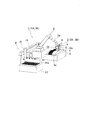
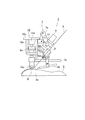
- FIG. 1 It is a perspective view which shows the schematic structure of the whole ATL apparatus which concerns on embodiment (1) of this invention. It is a side view which shows the structure of the ATL head in the ATL apparatus which concerns on embodiment (1). It is a side view which shows another state of the ATL head which concerns on embodiment (1) shown in FIG. It is a side view which shows the still another state of the ATL head which concerns on embodiment (1) shown in FIG. It is a perspective view which shows one state in the sticking process operation of the ATL apparatus which concerns on embodiment (1) shown in FIG. It is a side view which shows the structure of the ATL head in the ATL apparatus which concerns on embodiment (2). It is a side view which shows another state of the ATL head which concerns on embodiment (2) shown in FIG.
- FIG. 9A shows a state in which the telescopic rod is housed
- FIG. 9B shows a state in which the telescopic rod is extended.
- FIG. 9A shows a side view which shows the structural example of the ATL head in the conventional ATL apparatus.
- FIG. 1 is a perspective view showing a schematic configuration of the entire ATL device 1 according to the embodiment (1).
- the ATL device 1 is an articulated robot 2, an ATL head 3 attached to the tip of an arm 2a of the articulated robot 2, a tape conveying means 4 for supplying and conveying a tape A previously cut to the ATL head 3, and being cut. It is configured to include a mounting table 13 on which the tape A is placed, a work table 6 for holding the work 5, and the like.
- the work 5 in the present embodiment is reinforced by, for example, an injection-molded product of a thermoplastic resin, and a pre-cut (UD) tape A made of a carbon fiber bundle impregnated with the same thermoplastic resin is attached to the surface thereof. Will be done.
- the shape of the work 5, the position to attach the tape A, and the length to attach the tape A are predetermined by the design.
- the articulated robot 2 As the articulated robot 2, a commercially available general-purpose industrial robot can be used.
- the ATL head 3 is attached to the tip of the arm 2a of the articulated robot 2.
- the infrared lamp 8 and the hot air nozzle 18 are attached to the pressing means 10 side via the variable mechanism 7, and the variable mechanism 7 includes the link portion 7a and the slide portion 7b. Is configured to include.
- the infrared lamp 8 is supported by the link portion 7a
- the hot air nozzle 18 is supported by the slide portion 7b
- the relative position with respect to the pressing means 10 is, for example, from the position shown in FIG. 2 to the position shown in FIG. 3 or FIG. Up to, the link portion 7a and the slide portion 7b can be freely adjusted within the range allowed.
- both the infrared lamp 8 and the hot air nozzle 18 have variable positions relative to the pressing means 10 due to the action of the variable mechanism 7, but in another embodiment, the infrared lamp 8 and the hot air nozzle 18 are variable. At least one of them may be configured to have a variable relative position.
- the infrared lamp 8 is provided with an optical system (not shown) such as a reflector and a lens, and aims at a slightly upstream side of the attachment point shown by B in FIG. 2 and collects infrared rays in that region. It is configured so that the surface to be attached 5a existing in the region can be mainly heated.
- a non-contact temperature sensor 17 is attached to the case of the infrared lamp 8.
- the hot air nozzle 18 has a built-in heater (not shown), heats nitrogen gas supplied from a supply system (not shown), and ejects nitrogen gas as heating gas at a predetermined temperature and a predetermined flow rate from the tip thereof. It is configured in.
- the heating gas from the hot air nozzle 18 is also blown to a region slightly upstream of the sticking point B, and is configured to mainly heat the sticking surface 5a.
- the gas to be supplied may be carbon dioxide gas or air in addition to nitrogen gas.
- the feeder 9 is attached to the pressing means 10 via a variable mechanism 9A as an attachment means, and the variable mechanism 9A includes an arcuate slider portion 9a, a slide groove 9aa formed in the slider portion 9a, and the slide groove 9aa. It is configured to include an engaging projection (not shown) that engages with and slides.
- the engaging protrusion is formed on the case portion of the feeder 9, and the engaging protrusion slides in the slide groove 9aa to make the sticking angle of the tape A to the sticking surface 5a variable.
- the feeder 9 for holding and transporting the tape A has a built-in transport belts 11a and 11b, and the tape A is sandwiched and transported between the transport belts 11a and 11b.
- Heaters 12a and 12b are arranged inside the transport belts 11a and 11b so that the transport belts 11a and 11b can be preheated to a predetermined temperature.
- This preheating is not essential, and may not be necessary depending on the constituent materials, thickness, etc. of the tape A and the work 5.
- the pressing means 10 is configured such that the pressing roller 10a is attached to the base portion 10c via the roller support portion 10b.
- the pressing roller 10a presses the tape A against the surface to be attached 5a, and an air cylinder 10d that applies pressure to the pressing roller 10a is arranged in the roller support portion 10b.
- the tape transporting means 4 (FIG. 1) is a mounting table 13 on which tape A cut to a predetermined length is loaded, a pickup hand 14 that picks up tape A one by one from the mounting table 13, and a pickup hand 14 in the vertical direction. And the gantry shafts 15 and 16 to be moved in the horizontal direction are included.
- the pickup hand 14 includes a plurality of vacuum suction chucks 14a, and the vacuum suction chucks 14a pick up tapes A loaded on the mounting table 13 one by one.
- the work 5 to which the tape A is attached has various shapes (three-dimensional shapes). Therefore, in the ATL head 3, in order to keep the pressing state of the pressing roller 10a against the tape A constant, the pressing roller 10a is attached from the direction (normal direction) orthogonal to the tangential direction of the attachment surface 5a of the work 5.
- the posture (tilt) of the ATL head 3 is controlled so as to press. For example, the attitude control of the ATL head 3 with respect to the work 5 is performed based on the three-dimensional design data of the work 5.
- the attachment angle of the tape A to the attachment surface 5a is set in consideration of the constituent materials of the tape A.
- the constituent resin component of the tape A is made of PA-based nylon 6 (softening temperature around 180 ° C.)
- the variable mechanism 9A is operated to arrange the feeder 9 in a range close to the position shown in FIG. To do. That is, the sticking angle of the tape A to the sticking surface 5a is set to around 60 degrees, for example, 55 to 65 degrees.
- variable mechanism 9A is operated to move the feeder 9 to a range close to the position shown in FIG. Place in. That is, the sticking angle of the tape A to the sticking surface 5a is set to around 45 degrees, for example, 40 to 50 degrees.
- the relative positions of the infrared lamp 8 and the hot air nozzle 18 with respect to the pressing means 10 are determined.
- a heating process program as the heating means 80 according to the distance is set.
- variable mechanism 7 is operated to bring the infrared lamp 8 into a range close to the position shown in FIG.
- the position of the hot air nozzle 18 with respect to the pressing means 10 is determined, and the heating process program is set.
- variable mechanism 7 is operated to bring infrared rays into a range close to the position shown in FIG.
- the relative positions of the lamp 8 and the hot air nozzle 18 with respect to the pressing means 10 are determined, and the heating process program is set.
- the gantry shafts 15 and 16 operate, and the pickup hand 14 picks up only one tape A on the mounting table 13 (FIG. 5).
- the vacuum suction chuck 14a sucks and picks up the tape A with both ends (at least one end) of the tape A protruding from both ends of the pickup hand 14 in the length direction.
- the pickup hand 14 moves to the delivery position.
- the tape A held by the pickup hand 14 at the delivery position is delivered to the feeder 9 in the ATL head 3.
- the delivery position may be within the common area of the movable area of the pickup hand 14 by the gantry axes 15 and 16 and the movable area of the ATL head 3 by the articulated robot 2, and the position is not particularly limited.
- the articulated robot 2 operates so that one end of the tape A held by the pickup hand 14 is slightly inserted into the upper insertion port (not shown) of the feeder 9 in the ATL head 3, and the feeder 9 operates. Make a bowing action.
- the suction of the vacuum suction chuck 14a is released, and the tape A is delivered to the ATL head 3.
- the feeder 9 operates to convey the tape A to a predetermined standby position.
- the articulated robot 2 is operated to move the ATL head 3 to the attachment start position. Subsequently, the articulated robot 2 is operated to press the pressing roller 10a against the surface to be attached 5a.
- the feeder 9 operates at the timing when the pressing roller 10a comes into contact with the surface to be attached, and the tape A is conveyed so that the tip of the tape A is just sandwiched between the pressing roller 10a and the surface to be attached 5a. ..
- the infrared lamp 8 and the hot air nozzle 18 also start lighting and operation in synchronization with this timing, and start heating the surface to be attached 5a.
- the ATL head 3 moves and swings on the sticking surface 5a of the work 5 along the sticking path of the tape A, and sticks the tape A to the sticking surface 5a. During that time, the feeder 9 is operating to convey and supply the tape A.
- the infrared lamp 8 When the tape A is applied to the rear end of the surface to be attached 5a, the infrared lamp 8 is turned off, the operation of the hot air nozzle 18 is stopped, and the pressing roller 10a releases the pressing on the surface to be attached 5a by the operation of the articulated robot 2. Then, the application of one tape A is completed. Hereinafter, the same operation is repeated, and the tape A is attached onto the surface to be attached 5a.
- Production Example 1 Production of fiber reinforced resin molded body (A-1) An impregnated die in which carbon fiber "Treca” (registered trademark) T700S (12K) manufactured by Toray Industries, Inc. is aligned in one direction and filled with nylon 6 resin. A tape (A-1) having a width of 50 mm, a thickness of 0.28 mm, and a continuous fiber content of 60% by weight was obtained by pultrusion.
- Production Example 2 Production of Fiber Reinforced Resin Molded Body (A-2) An impregnated die in which carbon fiber "Treca” (registered trademark) T700S (12K) manufactured by Toray Industries, Inc. is aligned in one direction and filled with nylon 66 resin. A tape (A-2) having a width of 50 mm, a thickness of 0.28 mm, and a continuous fiber content of 60% by weight was obtained by pultrusion.
- Production Example 3 Production of fiber-reinforced resin molded product (A-3) A tape having a width of 50 mm and a continuous fiber content of 60% by weight using the same method as in Production Example 1 except that the thickness is changed to 0.15 mm. (A-3) was obtained.
- the work 5 shown in FIG. 1 was manufactured by injection molding using GF-reinforced nylon 6 (CM1011G-15 manufactured by Toray Industries, Inc.).
- Example 1 The fiber-reinforced resin molded product (A-1) according to Production Example 1 was adopted as the tape A, and the prepared tapes A were arranged on the mounting table 13 in the state shown in FIG.
- the variable mechanism 9A was operated to arrange the feeder 9 in a range close to the position shown in FIG. 2, and the attachment angle of the tape A to the attachment surface 5a was set to 60 degrees. Further, the variable mechanism 7 was used so that the relative positions of the infrared lamp 8 and the hot air nozzle 18 with respect to the pressing means 10 were close to the state shown in FIG. After that, considering the distance from the heating means 80 to the attachment point B, a heating process program as the heating means 80 was set according to this distance.
- the ATL device 1 was started, and the tape A was stuck on the sticking surface 5a of the work 5.
- the above-mentioned test piece was cut out from the molded product to which the tape A was attached, and each of the above evaluation tests was carried out. At the same time, the amount of electric power used in the heating means 80 was determined.
- Example 2 The fiber-reinforced resin molded product (A-2) according to Production Example 2 was adopted as the tape A, and the prepared tapes A were arranged on the mounting table 13 in the state shown in FIG.
- the variable mechanism 9A was operated to arrange the feeder 9 in a range close to the position shown in FIG. 3, and the attachment angle of the tape A to the attachment surface 5a was set to 45 degrees. Further, the variable mechanism 7 was used so that the relative positions of the infrared lamp 8 and the hot air nozzle 18 with respect to the pressing means 10 were close to the state shown in FIG. After that, considering the distance from the heating means 80 to the attachment point B, a heating process program as the heating means 80 was set according to this distance.
- the ATL device 1 was started, and the tape A was stuck on the sticking surface 5a of the work 5.
- the above-mentioned test piece was cut out from the molded product to which the tape A was attached, and each of the above evaluation tests was carried out. At the same time, the amount of electric power used in the heating means 80 was determined.
- Example 3 The fiber-reinforced resin molded product (A-2) according to Production Example 2 was adopted as the tape A, and the prepared tapes A were arranged on the mounting table 13 in the state shown in FIG.
- the variable mechanism 9A was operated to arrange the feeder 9 in a range close to the position shown in FIG. 4, and the attachment angle of the tape A to the attachment surface 5a was set to 45 degrees. Further, the variable mechanism 7 is used so that the relative positions of the infrared lamp 8 and the hot air nozzle 18 with respect to the pressing means 10 are close to the state shown in FIG. 4, that is, the infrared lamp 8 is located above the tape A. I set it up.
- a heating process program as the heating means 80 was set according to this distance. After that, the ATL device 1 was started, and the tape A was stuck on the sticking surface 5a of the work 5. The above-mentioned test piece was cut out from the molded product to which the tape A was attached, and each of the above evaluation tests was carried out. At the same time, the amount of electric power used in the heating means 80 was determined.
- Example 4 A molded product to which the tape A was attached was produced by the same method as in Example 2 except that the fiber-reinforced resin molded product (A-1) according to Production Example 1 was adopted as the tape A, and each evaluation test was performed. And the amount of electric power used in the heating means 80 was determined.
- Example 5 A molded product to which the tape A was attached was produced by the same method as in Example 2 except that the fiber-reinforced resin molded product (A-3) according to Production Example 3 was adopted as the tape A, and each evaluation test was performed. And the amount of electric power used in the heating means 80 was determined.
- Example 6 A molded product in which two tapes A are laminated and attached is produced by the same method as in Example 2 except that the fiber-reinforced resin molded product (A-3) according to Production Example 3 is used as the tape A. Then, each evaluation test was carried out, and the amount of electric power used in the heating means 80 was determined.
- the ATL device was started, and the tape A was stuck on the sticking surface 5a of the work 5.
- the above-mentioned test piece was cut out from the molded product to which the tape A was attached, and each of the above evaluation tests was carried out. At the same time, the amount of electric power used in the heating means 80 was determined.
- Example 2 In Example 1, the sticking test was carried out in the same manner except that the sticking angle of the tape A was changed to 5 degrees. As a result, the device interfered with the work 5, and the attachment was not completed.
- ⁇ Comparative example 4> A molded product in which two tapes A are laminated and attached is produced by using the same method as in Comparative Example 1 except that the fiber-reinforced resin molded product (A-3) according to Production Example 3 is used as the tape A. Then, each evaluation test was carried out, and the amount of electric power used in the heating means 80 was determined.
- Example 1 Bending strength (MPa) Flexural modulus (GPa) (1) Bending evaluation 364 20 (2) Heat resistance aging test 355 19 (3) Temperature and water resistance evaluation 350 18 (4) Power consumption Approximately 20% reduction compared to Comparative Example 1
- Example 2 Bending strength (MPa) Flexural modulus (GPa) (1) Bending evaluation 365 20 (2) Heat resistance aging test 358 19 (3) Temperature and water resistance evaluation 352 19 (4) Power consumption Approximately 30% reduction compared to Comparative Example 1
- Example 3 Bending strength (MPa) Flexural modulus (GPa) (1) Bending evaluation 366 21 (2) Heat resistance aging test 359 20 (3) Temperature and water resistance evaluation 353 20 (4) Power consumption Approximately 35% reduction compared to Comparative Example 1
- Example 4 Bending strength (MPa) Flexural modulus (GPa) (1) Bending evaluation 364 21 (2) Heat resistance aging test 360 21 (3) Temperature and water resistance evaluation 355 20 (4) Power consumption Approximately 40% reduction compared to Comparative Example 1
- Example 5 Bending strength (MPa) Flexural modulus (GPa) (1) Bending evaluation 280 16 (2) Heat resistance aging test 260 14 (3) Temperature and water resistance evaluation 260 14 (4) Power consumption Approximately 20% reduction compared to Comparative Example 2
- Example 6 Bending strength (MPa) Flexural modulus (GPa) (1) Bending evaluation 350 21 (2) Heat aging test 330 19 (3) Temperature and water resistance evaluation 330 19 (4) Power consumption Approximately 15% reduction compared to Comparative Example 3
- Comparative Example 1 Bending strength (MPa) Flexural modulus (GPa) (1) Bending evaluation 300 15 (2) Heat resistance aging test 250 12 (3) Temperature and water resistance evaluation 250 12 (4) Power consumption reference value
- MPa Flexural modulus
- GPa Heat resistance aging test
- the sticking angle of the tape A to the sticking surface 5a can be set to the optimum angle to proceed with the sticking process, and the sticking performance of the tape A to the sticking surface 5a can be advanced.
- a molded product having excellent bending characteristics, heat aging resistance, and heat water resistance was obtained.
- Comparative Examples 1 to 4 the performance related to tape sticking was insufficient, and any of bending characteristics, heat aging resistance, heat resistance and water resistance, and power consumption was insufficient.
- the distance from the heating means 80 to the surface to be attached 5a can be freely adjusted via the variable mechanism 7, and the heating means 80 is covered to the shortest distance within a range suitable for controlling the heating means 80. I was able to get closer to the sticking surface 5a.
- the amount of electric power used can be suppressed to the utmost limit, and the manufacturing cost of molded products can be significantly reduced. Further, while maintaining the optimum distance for controlling the heating means 80, it becomes easy to heat the surface to be attached 5a to the optimum temperature to proceed with the application process, and the tape A is attached to the surface to be attached 5a. It has also become easier to improve the strength of the molded product by improving the performance related to the product.
- control is performed while suppressing the manufacturing cost of the ATL device 1 and the running cost of the tape application process. It was also possible to improve the property and improve the finish of the molded product.
- the infrared lamp 8 above the tape A, it becomes easy to appropriately heat not only the surface to be attached 5a but also the tape A itself, and the performance related to the attachment of the tape A is improved to improve the performance of the molded product. It was also possible to improve the strength and appearance.
- tape A formed by putting continuous fibers into an impregnated die filled with polyamide resin and pulling it out from a slit die is used to produce a composite molded product with excellent strength and appearance while significantly reducing manufacturing costs. I was able to manufacture it.
- the ATL apparatus, the tape attaching method, and the manufacturing method of the composite molded product according to the embodiment (2) will be described with reference to FIGS. 1, 5 to 7.
- the configuration of the ATL device 1A according to the embodiment (2) is the same as that of the ATL device 1 shown in FIGS. 1 and 5 except for the ATL head 3A
- the ATL head 3A is designated by a different reference numeral.
- Other components having the same function are designated by the same reference numerals, and the description thereof will be omitted here.
- the feeder 9 of the ATL head 3 is attached to the pressing means 10 via the variable mechanism 9A as the attaching means.
- the ATL device 1A according to the embodiment (2) is not equipped with the above-mentioned variable mechanism 9A, and the feeder 9 of the ATL head 3A presses the means 10 via, for example, the base material 70 as shown in FIG. It is attached to.
- the infrared lamp 8 and the hot air nozzle 18 are attached to the pressing means 10 side via the variable mechanism 7, and the variable mechanism 7 includes the link portion 7a and the slide portion 7b. Is configured to include.
- the infrared lamp 8 is supported by the link portion 7a
- the hot air nozzle 18 is supported by the slide portion 7b
- the relative positions with respect to the pressing means 10 are, for example, from the position shown in FIG. 6 to the position shown in FIG. It can be freely adjusted within the range allowed by the link portion 7a and the slide portion 7b.
- both the infrared lamp 8 and the hot air nozzle 18 have variable positions relative to the pressing means 10 due to the action of the variable mechanism 7, but in another embodiment, the infrared lamp 8 and the hot air nozzle 18 are variable. At least one of the hot air nozzles 18 may be configured to have a variable relative position.
- the feeder 9 (FIG. 1) exists, it is omitted in FIGS. 6 and 7 and is not shown in order to illustrate the entire variable mechanism 7.
- the feeder 9 for holding and transporting the tape A has a built-in transport belts 11a and 11b, and the tape A is sandwiched and transported between the transport belts 11a and 11b.
- Heaters 12a and 12b are arranged inside the transport belts 11a and 11b so that the transport belts 11a and 11b can be preheated to a predetermined temperature.
- This preheating is not essential, and may not be necessary depending on the constituent materials, thickness, etc. of the tape A and the work 5.
- the work 5 to which the tape A is attached has various shapes (three-dimensional shapes). Therefore, in the ATL head 3A, in order to keep the pressing state of the pressing roller 10a against the tape A constant, the pressing roller 10a is attached from the direction (normal direction) orthogonal to the tangential direction of the attachment surface 5a of the work 5.
- the posture (tilt) of the ATL head 3A is controlled so as to press. For example, the attitude control of the ATL head 3A with respect to the work 5 is performed based on the three-dimensional design data of the work 5.
- the relative positions of the infrared lamp 8 and the hot air nozzle 18 with respect to the pressing means 10 (FIGS. 6 and 7), in other words, the distance relationship to the sticking point B is determined, and this distance is determined.
- a heating process program as the heating means 80 is set according to the above.
- variable mechanism 7 is operated to bring the infrared lamp 8 into a range close to the position shown in FIG.
- the position of the hot air nozzle 18 with respect to the pressing means 10 is determined, and the heating process program is set.
- variable mechanism 7 is operated to bring infrared rays into a range close to the position shown in FIG.
- the relative positions of the lamp 8 and the hot air nozzle 18 with respect to the pressing means 10 are determined, and the heating process program is set.
- the gantry shafts 15 and 16 operate, and the pickup hand 14 picks up only one tape A on the mounting table 13 (FIG. 5).
- the vacuum suction chuck 14a sucks and picks up the tape A with both ends (at least one end) of the tape A protruding from both ends of the pickup hand 14 in the length direction.
- the pickup hand 14 moves to the delivery position.
- the tape A held by the pickup hand 14 at the delivery position is delivered to the feeder 9 in the ATL head 3A.
- the delivery position may be within the common area of the movable area of the pickup hand 14 by the gantry axes 15 and 16 and the movable area of the ATL head 3A by the articulated robot 2, and the position is not particularly limited.
- the articulated robot 2 operates so that one end of the tape A held by the pickup hand 14 is slightly inserted into the upper insertion port (not shown) of the feeder 9 in the ATL head 3A, and the feeder 9 operates. Make a bowing action.
- the suction of the vacuum suction chuck 14a is released, and the tape A is delivered to the ATL head 3A.
- the feeder 9 operates to convey the tape A to a predetermined standby position.
- the articulated robot 2 is operated to move the ATL head 3A to the attachment start position. Subsequently, the articulated robot 2 is operated to press the pressing roller 10a against the surface to be attached 5a.
- the feeder 9 operates at the timing when the pressing roller 10a comes into contact with the surface to be attached, and the tape A is conveyed so that the tip of the tape A is just sandwiched between the pressing roller 10a and the surface to be attached 5a. ..
- the infrared lamp 8 and the hot air nozzle 18 also start lighting and operation in synchronization with this timing, and start heating the surface to be attached 5a.
- the ATL head 3A moves and swings on the sticking surface 5a of the work 5 along the sticking path of the tape A, and sticks the tape A to the sticking surface 5a. During that time, the feeder 9 is operating to convey and supply the tape A.
- the infrared lamp 8 When the tape A is applied to the rear end of the surface to be attached 5a, the infrared lamp 8 is turned off, the operation of the hot air nozzle 18 is stopped, and the pressing roller 10a releases the pressing on the surface to be attached 5a by the operation of the articulated robot 2. Then, the application of one tape A is completed. Hereinafter, the same operation is repeated, and the tape A is attached onto the surface to be attached 5a.
- Production Example 1 Production of Fiber Reinforced Resin Molded Body (A-1)
- Production Example 2 Production of Fiber Reinforced Resin Molded Body (A-2)
- Production Example 3 Production of Fiber Reinforced Resin Molded Body (A-2) Since the manufacturing of A-3) and the manufacturing of the work are the same, the description thereof will be omitted here.
- Example 11 The fiber-reinforced resin molded product (A-1) according to Production Example 1 was adopted as the tape A, and the prepared tapes A were arranged on the mounting table 13 in the state shown in FIG.
- the variable mechanism 7 was used so that the relative positions of the infrared lamp 8 and the hot air nozzle 18 with respect to the pressing means 10 were close to the state shown in FIG.
- a heating process program as the heating means 80 was set according to this distance.
- the ATL device 1A was started, and the tape A was stuck on the sticking surface 5a of the work 5.
- the above-mentioned test piece was cut out from the molded product to which the tape A was attached, and each of the above evaluation tests was carried out. At the same time, the amount of electric power used in the heating means 80 was determined.
- Example 12 The fiber-reinforced resin molded product (A-2) according to Production Example 2 was adopted as the tape A, and the prepared tapes A were arranged on the mounting table 13 in the state shown in FIG.
- the variable mechanism 7 was used so that the relative positions of the infrared lamp 8 and the hot air nozzle 18 with respect to the pressing means 10 were close to the state shown in FIG.
- a heating process program as the heating means 80 was set according to this distance.
- the ATL device 1A was started, and the tape A was stuck on the sticking surface 5a of the work 5.
- the above-mentioned test piece was cut out from the molded product to which the tape A was attached, and each of the above evaluation tests was carried out. At the same time, the amount of electric power used in the heating means 80 was determined.
- Example 13> The fiber-reinforced resin molded product (A-2) according to Production Example 2 was adopted as the tape A, and the prepared tapes A were arranged on the mounting table 13 in the state shown in FIG. The slide portion 7b and the link portion so that the relative position of the hot air nozzle 18 with respect to the pressing means 10 is close to the state shown in FIG. 7 and the infrared lamp 8 is located above the tape A (not shown). It was set using 7a. After that, considering the distance from the heating means 80 to the attachment point B, a heating process program as the heating means 80 was set according to this distance. After that, the ATL device 1A was started, and the tape A was stuck on the sticking surface 5a of the work 5. The above-mentioned test piece was cut out from the molded product to which the tape A was attached, and each of the above evaluation tests was carried out. At the same time, the amount of electric power used in the heating means 80 was determined.
- Example 14 A molded product to which the tape A was attached was produced by the same method as in Example 13 except that the fiber-reinforced resin molded product (A-1) according to Production Example 1 was adopted as the tape A, and each evaluation test was performed. And the amount of electric power used in the heating means 80 was determined.
- Example 15 A molded product to which the tape A was attached was prepared by the same method as in Example 13 except that the fiber-reinforced resin molded product (A-3) according to Production Example 3 was adopted as the tape A, and each evaluation test was performed. And the amount of electric power used in the heating means 80 was determined.
- Example 16 A molded product in which two tapes A are laminated and attached is produced by the same method as in Example 13 except that the fiber-reinforced resin molded product (A-3) according to Production Example 3 is used as the tape A. Then, each evaluation test was carried out, and the amount of electric power used in the heating means 80 was determined.
- ⁇ Comparative Example 12> A molded product to which the tape A was attached was produced by the same method as in Comparative Example 11 except that the fiber-reinforced resin molded product (A-3) according to Production Example 3 was adopted as the tape A, and each evaluation test was performed. And the amount of electric power used in the heating means 80 was determined.
- ⁇ Comparative Example 13> A molded product in which two tapes A are laminated and attached is produced by the same method as in Comparative Example 11 except that the fiber-reinforced resin molded product (A-3) according to Production Example 3 is used as the tape A. Then, each evaluation test was carried out, and the amount of electric power used in the heating means 80 was determined.
- Example 11 Bending strength (MPa) Flexural modulus (GPa) (1) Bending evaluation 360 20 (2) Heat aging test 350 19 (3) Temperature and water resistance evaluation 350 18 (4) Power consumption Approximately 20% reduction compared to Comparative Example 11
- Example 12 Bending strength (MPa) Flexural modulus (GPa) (1) Bending evaluation 360 20 (2) Heat aging test 350 19 (3) Temperature and water resistance evaluation 350 19 (4) Power consumption Approximately 30% reduction compared to Comparative Example 11
- Example 13 Bending strength (MPa) Flexural modulus (GPa) (1) Bending evaluation 360 21 (2) Heat resistance aging test 350 20 (3) Temperature and water resistance evaluation 340 20 (4) Power consumption Approximately 35% reduction compared to Comparative Example 11
- Example 14 Bending strength (MPa) Flexural modulus (GPa) (1) Bending evaluation 370 21 (2) Heat resistance aging test 360 20 (3) Temperature and water resistance evaluation 365 20 (4) Power consumption Approximately 40% reduction compared to that of Comparative Example 11
- Example 15 Bending strength (MPa) Flexural modulus (GPa) (1) Bending evaluation 280 16 (2) Heat resistance aging test 260 14 (3) Temperature and water resistance evaluation 260 14 (4) Power consumption Approximately 20% reduction compared to Comparative Example 12
- Example 16 Bending strength (MPa) Flexural modulus (GPa) (1) Bending evaluation 350 21 (2) Heat aging test 330 19 (3) Temperature and water resistance evaluation 330 19 (4) Power consumption Approximately 15% reduction compared to Comparative Example 13
- the distance from the heating means 80 to the surface to be attached 5a can be freely adjusted via the variable mechanism 7, and is a range suitable for controlling the heating means 80.
- the heating means 80 can be brought close to the surface to be attached 5a to the shortest distance inside. Therefore, the amount of electric power used can be suppressed to the utmost limit, and the manufacturing cost of the molded product can be significantly reduced. Further, since the capacity (output) of the heating means 80 can be reduced, a small and inexpensive heating means can be selected, and further, the heating region can be optimized, and heating of only the necessary part can be realized. It is also possible to suppress the influence of heat on the surrounding area (where it is not pasted).
- the heating means 80 while maintaining the optimum distance for controlling the heating means 80, it becomes easy to heat the surface to be attached 5a to the optimum temperature to proceed with the application process, and the tape A is attached to the surface to be attached 5a. It has also become easier to improve the strength of the molded product by improving the performance related to the product.
- control is performed while suppressing the manufacturing cost of the ATL device 1A and the running cost of the tape application process. It was also possible to improve the property and improve the finish of the molded product.
- the infrared lamp 8 above the tape A, it becomes easy to appropriately heat not only the surface to be attached 5a but also the tape A itself, and the performance related to the attachment of the tape A is improved to improve the performance of the molded product. It was also possible to improve the strength and appearance finish.
- tape A formed by putting continuous fibers into an impregnated die filled with polyamide resin and pulling it out from the slit die in one direction, a composite with excellent strength and appearance while significantly reducing manufacturing costs. I was able to manufacture a molded product.
- the ATL apparatus, the tape sticking method, and the manufacturing method of the composite molded product according to the embodiment (3) will be described with reference to FIGS. 1, 5, 8 and 9.
- the ATL device 1B according to the embodiment (3) has the embodiment (1) shown in FIGS. 1 and 5 except that the tape supporting means 9B is attached to the lower part of the feeder 9 of the ATL head 3B. ), Since it is the same as the ATL device 1, other components having the same function are designated by the same reference numerals, and the description thereof will be omitted here.
- the feeder 9 is attached to the pressing means 10 via a variable mechanism 9A as an attachment means, and the variable mechanism 9A is a slide groove formed in the arc-shaped slider portion 9a and the slider portion 9a. 9aa, including an engaging projection (not shown) that engages and slides with the slide groove 9aa.
- the engaging protrusions are formed on the case portion of the feeder 9, and the engaging protrusions slide and move in the slide groove 9aa to make the sticking angle of the tape A to the sticking surface 5a variable.
- a tape supporting means 9B is attached to the lower part of the feeder 9, and the tape supporting means 9B is attached to a tape supporting portion 9b having a roller for supporting the tape A and a tape supporting portion 9b attached to the lower part of the feeder 9. It is configured to include a support rod 9ba that connects the lower part of the feeder 9.
- the tape supporting means 9B supports the tip end side of the tape A transported from the feeder 9 to the affixed surface 5a, and the tape A is attached to the affixed surface 5a. Can surely lead to.
- FIGS. 9 (a) and 9 (b) show the tape supporting means 9B'according to another embodiment
- FIG. 9 (a) shows a state in which the telescopic rod 9bb is housed.
- FIG. 9B shows a state in which the telescopic rod 9bb is extended.
- the tape supporting portion 9b is configured to be movable from the feeder 9 side to the attachment surface 5a side, and the tape A is the feeder 9
- the tape A can be guided from the outlet of the feeder 9 to the surface to be attached 5a more reliably. Therefore, the above-mentioned effect in the above-mentioned tape supporting means 9B shown in FIG. 8 can be further ensured.
- the feeder 9 for holding and transporting the tape A has a built-in transport belts 11a and 11b, and the tape A is sandwiched and transported between the transport belts 11a and 11b.
- Heaters 12a and 12b are arranged inside the transport belts 11a and 11b so that the transport belts 11a and 11b can be preheated to a predetermined temperature.
- This preheating is not essential, and may not be necessary depending on the constituent materials, thickness, etc. of the tape A and the work 5.
- the work 5 to which the tape A is attached has various shapes (three-dimensional shapes). Therefore, in the ATL head 3B, in order to keep the pressing state of the pressing roller 10a against the tape A constant, the pressing roller 10a is attached from the direction (normal direction) orthogonal to the tangential direction of the attachment surface 5a of the work 5.
- the posture (tilt) of the ATL head 3B is controlled so as to press. For example, the attitude control of the ATL head 3B with respect to the work 5 is performed based on the three-dimensional design data of the work 5.
- the attachment angle of the tape A to the attachment surface 5a is set in consideration of the constituent materials of the tape A.
- the constituent resin component of the tape A is PA-based nylon 6 (softening temperature around 180 ° C.)
- the variable mechanism 9A is operated to arrange the feeder 9 in a range close to the position shown in FIG. To do. That is, the sticking angle of the tape A to the sticking surface 5a is set to around 60 degrees, for example, 55 to 65 degrees.
- variable mechanism 9A when the constituent resin component of the tape A is made of PA-based nylon 66 (softening temperature of about 230 ° C.), the variable mechanism 9A is operated to position the feeder 9 from the position shown in FIG. Is arranged in a low range, and for example, the attachment angle of the tape A to the attachment surface 5a is set to be around 45 degrees, for example, 40 to 50 degrees.
- the relative positions of the infrared lamp 8 and the hot air nozzle 18 with respect to the pressing means 10, in other words, the distance relationship to the sticking point B are determined, and the heating means according to this distance is determined.
- a heating process program as 80 is set.
- variable mechanism 7 is operated to bring the infrared lamp 8 into a range close to the position shown in FIG.
- the position of the hot air nozzle 18 with respect to the pressing means 10 is determined, and the heating process program is set.
- variable mechanism 7 when the constituent resin component of the tape A is made of PA-based nylon 66 (softening temperature around 230 ° C.), the variable mechanism 7 is operated so that the position is closer than the position shown in FIG.
- the relative positions of the infrared lamp 8 and the hot air nozzle 18 with respect to the pressing means 10 are determined, and a heating process program is set.
- the gantry shafts 15 and 16 operate, and the pickup hand 14 picks up only one tape A on the mounting table 13 (FIG. 5).
- the vacuum suction chuck 14a sucks and picks up the tape A with both ends (at least one end) of the tape A protruding from both ends of the pickup hand 14 in the length direction.
- the pickup hand 14 moves to the delivery position.
- the tape A held by the pickup hand 14 at the delivery position is delivered to the feeder 9 in the ATL head 3B.
- the delivery position may be within the common area of the movable area of the pickup hand 14 by the gantry axes 15 and 16 and the movable area of the ATL head 3B by the articulated robot 2, and the position is not particularly limited.
- the articulated robot 2 operates so that one end of the tape A held by the pickup hand 14 is slightly inserted into the upper insertion port (not shown) of the feeder 9 in the ATL head 3B, and the feeder 9 operates. Make a bowing action.
- the suction of the vacuum suction chuck 14a is released, and the tape A is delivered to the ATL head 3B.
- the feeder 9 operates to convey the tape A to a predetermined standby position.
- the articulated robot 2 is operated to move the ATL head 3B to the attachment start position. Subsequently, the articulated robot 2 is operated to press the pressing roller 10a against the surface to be attached 5a.
- the feeder 9 operates at the timing when the pressing roller 10a comes into contact with the surface to be attached, and the tape support portion 9b is held so that the tip of the tape A is sandwiched between the pressing roller 10a and the surface to be attached 5a.
- the tape A is conveyed through the tape A.
- the infrared lamp 8 and the hot air nozzle 18 also start lighting and operation in synchronization with this timing, and start heating the surface to be attached 5a.
- the ATL head 3B moves and swings on the sticking surface 5a of the work 5 along the sticking path of the tape A, and sticks the tape A to the sticking surface 5a. During that time, the feeder 9 is operating to convey and supply the tape A.
- the infrared lamp 8 When the tape A is applied to the rear end of the surface to be attached 5a, the infrared lamp 8 is turned off, the operation of the hot air nozzle 18 is stopped, and the pressing roller 10a releases the pressing on the surface to be attached 5a by the operation of the articulated robot 2. Then, the application of one tape A is completed. Hereinafter, the same operation is repeated, and the tape A is attached onto the surface to be attached 5a.
- the tip side of the tape A conveyed from the feeder 9 to the affixed surface 5a at the start stage of the affixing step of the tape A to the affixed surface 5a by the tape supporting means 9B.
- the tape A can be reliably guided to the surface to be attached 5a.
- the tape supporting portion 9b moves from the feeder 9 side to the attachment surface 5a side. Since it is configured to be movable, the tape A can be guided from the outlet of the feeder 9, and the tape A can be more reliably guided from the outlet of the feeder 9 to the surface to be attached 5a. Further, in the case of the tape supporting means 9B', when the tape A sticking operation is started, the tape supporting portion 9b is returned to the state where the telescopic rod 9bb is stored (the state shown in FIG. 9A). It is also possible.
- the sticking angle of the tape A to the sticking surface 5a can be set to an optimum angle to proceed with the sticking process, and the tape sticking to the sticking surface 5a is related.
- the performance can be improved and the strength of the molded product can be improved.
- the finish of the molded product can be improved. Further, by keeping the sticking angle at 10 degrees or more, it is possible to prevent the occurrence of a contact accident of the ATL head 3B with the sticking surface 5a.
- the distance from the heating means 80 to the surface to be attached 5a can be freely adjusted via the variable mechanism 7, and the heating means 80 is covered to the shortest distance within a range suitable for controlling the heating means 80. It can be brought close to the sticking surface 5a.
- the amount of electric power used can be suppressed to the utmost limit, and the manufacturing cost of molded products can be significantly reduced. Further, while maintaining the optimum distance for controlling the heating means 80, it becomes easy to heat the surface to be attached 5a to the optimum temperature to proceed with the application process, and the performance related to tape application to the surface to be attached 5a. It also becomes easy to improve the strength, appearance, etc. of the molded product.
- the manufacturing cost of the ATL device 1B and the running cost of the tape application process can be suppressed while controlling. It is also possible to improve the property and improve the finish of the molded product.
- the infrared lamp 8 is arranged above the tape A, it becomes easy to appropriately heat not only the surface to be attached 5a but also the tape A itself, and the performance related to the tape attachment is enhanced to increase the strength of the molded product. It can also be improved.
- tape A formed by putting continuous fibers into an impregnated die filled with polyamide resin and pulling it out from a slit die is used to produce a composite molded product with excellent strength and appearance while significantly reducing manufacturing costs. Can be manufactured.
- a gantry structure is used for the tape transport means 4, but in another embodiment, an articulated robot is used instead of the gantry structure. You may.
- the articulated robot 2 is adopted as the driving device for the ATL heads 3, 3A and 3B, but in another embodiment, the articulated robot is replaced.
- a gantry structure may be adopted.
- the motion control of the ATL heads 3, 3A and 3B in the XYZ axis direction can be stably performed. Further, the rigidity of the ATL heads 3, 3A and 3B can be increased, the pressing force of the ATL heads 3, 3A and 3B can be increased, and the footprints of the ATL devices 1, 1A and 1B (in other words, in other words). It is also possible to obtain the advantage that the occupied volume including the operating range of the entire device can be reduced.
- the infrared lamp 8 is adopted as one of the heating means 80, but in another embodiment, a laser light source is used as the heating source of the radiant energy method. It may be adopted.
- the laser light source has the advantages of high output, high energy density, and easy output control. However, the oscillator tube, optical fiber (light guide tube), optical system, power supply, control device, etc. are a little expensive.
- ATL device (tape sticking device) 2 Articulated robot 2a Arm 3, 3A, 3B ATL head (attached head) 4 Tape transport means 5 Work 5a Attached surface 6 Work base 7 Variable mechanism 7a Link part 7b Slide part 8 Infrared lamp 9 Feeder (tape supply means) 9A variable mechanism (mounting means) 9a Slider part 9aa Slide groove 9B Tape support means 9b Tape support part 9ba Support rod 9B'Tape support means 9bb Telescopic rod 10 Pressing means 10a Pressing roller 10b Roller support part 10c Base part 10d Cylinder part 11a, 11b Conveyor belt 12a, 12b Heater 13 Mounting stand 14 Pickup hand 14a Vacuum suction chuck 15 Gantry shaft 16 Gantry shaft 17 Temperature sensor 18 Hot air nozzle 80 Heating means 30 ATL head (conventional) 70 Base material (conventional) A tape B sticking point
Landscapes
- Engineering & Computer Science (AREA)
- Mechanical Engineering (AREA)
- Chemical & Material Sciences (AREA)
- Composite Materials (AREA)
- Textile Engineering (AREA)
- Robotics (AREA)
- Manufacturing & Machinery (AREA)
- Lining Or Joining Of Plastics Or The Like (AREA)
Abstract
Un objectif de la présente invention est de fournir un dispositif d'application de ruban capable d'améliorer les performances relatives à l'application d'un ruban sur une surface d'application lors de la fabrication d'un article moulé en plastique renforcé de fibres par application d'un ruban sur la surface d'application, ledit dispositif étant un dispositif ATL 1 muni d'une tête ATL 3 qui presse et applique un ruban A sur une surface d'application 5a, la tête ATL 3 étant pourvue d'un dispositif d'alimentation 9 qui amène le ruban A jusqu'à la surface d'application 5a, d'un moyen de pression 10 pour presser le ruban A contre la surface d'application 5a et d'un moyen de chauffage 80 pour chauffer le ruban A et/ou la surface d'application 5a. Le dispositif d'alimentation 9 est fixé au moyen de pression 10 par l'intermédiaire d'un mécanisme variable 9A interposé entre eux de telle sorte que l'angle d'application du ruban A sur la surface d'application 5a est égal ou supérieur à 10° et égal ou inférieur à 70°.
Applications Claiming Priority (6)
| Application Number | Priority Date | Filing Date | Title |
|---|---|---|---|
| JP2019-130086 | 2019-07-12 | ||
| JP2019130086 | 2019-07-12 | ||
| JP2019-130087 | 2019-07-12 | ||
| JP2019130087 | 2019-07-12 | ||
| JP2019-130085 | 2019-07-12 | ||
| JP2019130085 | 2019-07-12 |
Publications (1)
| Publication Number | Publication Date |
|---|---|
| WO2021010318A1 true WO2021010318A1 (fr) | 2021-01-21 |
Family
ID=74210908
Family Applications (1)
| Application Number | Title | Priority Date | Filing Date |
|---|---|---|---|
| PCT/JP2020/027029 Ceased WO2021010318A1 (fr) | 2019-07-12 | 2020-07-10 | Dispositif d'application de ruban, procédé d'application de ruban et procédé de fabrication d'article moulé composite |
Country Status (2)
| Country | Link |
|---|---|
| TW (1) | TW202120305A (fr) |
| WO (1) | WO2021010318A1 (fr) |
Cited By (5)
| Publication number | Priority date | Publication date | Assignee | Title |
|---|---|---|---|---|
| CN115008785A (zh) * | 2022-06-27 | 2022-09-06 | 中航复合材料有限责任公司 | 一种适用于z形复合材料机身隔框毛坯的压实装置 |
| WO2022201675A1 (fr) * | 2021-03-23 | 2022-09-29 | 東レエンジニアリング株式会社 | Dispositif de fixation de ruban et procédé de fixation de ruban |
| CN115847797A (zh) * | 2022-11-02 | 2023-03-28 | 常州福佑达智能装备科技有限公司 | 光伏贴膜机 |
| CN115892588A (zh) * | 2022-11-02 | 2023-04-04 | 常州福佑达智能装备科技有限公司 | 用于光伏贴膜机的吹膜导风装置 |
| US20240227324A9 (en) * | 2022-10-25 | 2024-07-11 | Industrial Technology Research Institute | A tape laying device |
Citations (5)
| Publication number | Priority date | Publication date | Assignee | Title |
|---|---|---|---|---|
| JP2006264064A (ja) * | 2005-03-23 | 2006-10-05 | Fuji Photo Film Co Ltd | 積層体のラミネート方法及びラミネート装置 |
| JP2008515665A (ja) * | 2004-10-05 | 2008-05-15 | ザ・ボーイング・カンパニー | 複合テープの敷設方法 |
| JP2017163092A (ja) * | 2016-03-11 | 2017-09-14 | リンテック株式会社 | シート貼付装置および貼付方法 |
| JP2018149729A (ja) * | 2017-03-13 | 2018-09-27 | 東レエンジニアリング株式会社 | 繊維束貼付装置 |
| WO2019122431A1 (fr) * | 2017-12-22 | 2019-06-27 | Mubea Carbo Tech Gmbh | Système de pose de ruban de fibres |
-
2020
- 2020-07-10 WO PCT/JP2020/027029 patent/WO2021010318A1/fr not_active Ceased
- 2020-07-10 TW TW109123412A patent/TW202120305A/zh unknown
Patent Citations (5)
| Publication number | Priority date | Publication date | Assignee | Title |
|---|---|---|---|---|
| JP2008515665A (ja) * | 2004-10-05 | 2008-05-15 | ザ・ボーイング・カンパニー | 複合テープの敷設方法 |
| JP2006264064A (ja) * | 2005-03-23 | 2006-10-05 | Fuji Photo Film Co Ltd | 積層体のラミネート方法及びラミネート装置 |
| JP2017163092A (ja) * | 2016-03-11 | 2017-09-14 | リンテック株式会社 | シート貼付装置および貼付方法 |
| JP2018149729A (ja) * | 2017-03-13 | 2018-09-27 | 東レエンジニアリング株式会社 | 繊維束貼付装置 |
| WO2019122431A1 (fr) * | 2017-12-22 | 2019-06-27 | Mubea Carbo Tech Gmbh | Système de pose de ruban de fibres |
Cited By (9)
| Publication number | Priority date | Publication date | Assignee | Title |
|---|---|---|---|---|
| WO2022201675A1 (fr) * | 2021-03-23 | 2022-09-29 | 東レエンジニアリング株式会社 | Dispositif de fixation de ruban et procédé de fixation de ruban |
| JP2022147579A (ja) * | 2021-03-23 | 2022-10-06 | 東レエンジニアリング株式会社 | テープ貼付装置、及びテープ貼付方法 |
| JP7584339B2 (ja) | 2021-03-23 | 2024-11-15 | 東レエンジニアリング株式会社 | テープ貼付装置、及びテープ貼付方法 |
| CN115008785A (zh) * | 2022-06-27 | 2022-09-06 | 中航复合材料有限责任公司 | 一种适用于z形复合材料机身隔框毛坯的压实装置 |
| CN115008785B (zh) * | 2022-06-27 | 2023-08-22 | 中航复合材料有限责任公司 | 一种适用于z形复合材料机身隔框毛坯的压实装置 |
| US20240227324A9 (en) * | 2022-10-25 | 2024-07-11 | Industrial Technology Research Institute | A tape laying device |
| US12358240B2 (en) * | 2022-10-25 | 2025-07-15 | Industrial Technology Research Institute | Tape laying device |
| CN115847797A (zh) * | 2022-11-02 | 2023-03-28 | 常州福佑达智能装备科技有限公司 | 光伏贴膜机 |
| CN115892588A (zh) * | 2022-11-02 | 2023-04-04 | 常州福佑达智能装备科技有限公司 | 用于光伏贴膜机的吹膜导风装置 |
Also Published As
| Publication number | Publication date |
|---|---|
| TW202120305A (zh) | 2021-06-01 |
Similar Documents
| Publication | Publication Date | Title |
|---|---|---|
| WO2021010318A1 (fr) | Dispositif d'application de ruban, procédé d'application de ruban et procédé de fabrication d'article moulé composite | |
| JP6900417B2 (ja) | 繊維束貼付方法および繊維強化プラスチック製品の製造方法 | |
| JP2018149730A (ja) | 繊維束貼付装置 | |
| JP2018149729A (ja) | 繊維束貼付装置 | |
| JP5663581B2 (ja) | 自動化ドレープ形成装置 | |
| JP6195933B2 (ja) | 繊維プリフォームを製造する方法 | |
| US10369594B2 (en) | Fiber application head with a specific application roll | |
| JP2013505155A5 (fr) | ||
| JP6000330B2 (ja) | 特に繊維強化プラスチック部材を製造する際の予備成形体である、繊維プリフォームを製造する装置及び方法 | |
| US11883990B2 (en) | Holding member, work molding system, and work molding method | |
| US10464242B2 (en) | Convey device, molded article manufacturing apparatus, and method of manufacturing molded article | |
| JP2021014119A (ja) | テープ貼付装置、テープ貼付方法、及び複合成形品の製造方法 | |
| CN107107415A (zh) | 立式注塑成型机及使用立式注塑成型机的复合成型体的成型方法 | |
| CN104254434A (zh) | 用于制造塑料成形件的方法 | |
| JP7686948B2 (ja) | テープ貼付装置、テープ貼付方法、及び複合成形品の製造方法 | |
| JP6211503B2 (ja) | 成形品の製造方法、成形品、および成形品の製造装置 | |
| JP2021014121A (ja) | テープ貼付装置、テープ貼付方法、及び複合成形品の製造方法 | |
| JP7015268B2 (ja) | 繊維束貼付方法および成形品の製造方法 | |
| JP6195932B2 (ja) | 強化繊維束を制御して堆積させる堆積装置 | |
| EP2802446B1 (fr) | Procede et systeme de fabrication d'un article composite | |
| WO2021199700A1 (fr) | Procédé de collage de faisceau de fibres | |
| KR102331287B1 (ko) | 예비 성형체를 제조하기 위한 장치 및 방법 | |
| JP2021160129A (ja) | 繊維束貼り付け装置 | |
| JP2000309033A (ja) | 射出成形同時絵付方法及び装置 | |
| JP2024135645A (ja) | テープ貼付装置 |
Legal Events
| Date | Code | Title | Description |
|---|---|---|---|
| 121 | Ep: the epo has been informed by wipo that ep was designated in this application |
Ref document number: 20839582 Country of ref document: EP Kind code of ref document: A1 |
|
| NENP | Non-entry into the national phase |
Ref country code: DE |
|
| 122 | Ep: pct application non-entry in european phase |
Ref document number: 20839582 Country of ref document: EP Kind code of ref document: A1 |