WO2021015257A1 - Système de réception d'énergie sans fil, ensemble pneu/roue, et pneu - Google Patents
Système de réception d'énergie sans fil, ensemble pneu/roue, et pneu Download PDFInfo
- Publication number
- WO2021015257A1 WO2021015257A1 PCT/JP2020/028511 JP2020028511W WO2021015257A1 WO 2021015257 A1 WO2021015257 A1 WO 2021015257A1 JP 2020028511 W JP2020028511 W JP 2020028511W WO 2021015257 A1 WO2021015257 A1 WO 2021015257A1
- Authority
- WO
- WIPO (PCT)
- Prior art keywords
- tire
- power
- power receiving
- magnetic material
- carcass
- Prior art date
- Legal status (The legal status is an assumption and is not a legal conclusion. Google has not performed a legal analysis and makes no representation as to the accuracy of the status listed.)
- Ceased
Links
Images


Classifications
-
- B—PERFORMING OPERATIONS; TRANSPORTING
- B60—VEHICLES IN GENERAL
- B60C—VEHICLE TYRES; TYRE INFLATION; TYRE CHANGING; CONNECTING VALVES TO INFLATABLE ELASTIC BODIES IN GENERAL; DEVICES OR ARRANGEMENTS RELATED TO TYRES
- B60C15/00—Tyre beads, e.g. ply turn-up or overlap
- B60C15/06—Flipper strips, fillers, or chafing strips and reinforcing layers for the construction of the bead
- B60C15/0603—Flipper strips, fillers, or chafing strips and reinforcing layers for the construction of the bead characterised by features of the bead filler or apex
-
- B—PERFORMING OPERATIONS; TRANSPORTING
- B60—VEHICLES IN GENERAL
- B60C—VEHICLE TYRES; TYRE INFLATION; TYRE CHANGING; CONNECTING VALVES TO INFLATABLE ELASTIC BODIES IN GENERAL; DEVICES OR ARRANGEMENTS RELATED TO TYRES
- B60C15/00—Tyre beads, e.g. ply turn-up or overlap
- B60C15/04—Bead cores
-
- B—PERFORMING OPERATIONS; TRANSPORTING
- B60—VEHICLES IN GENERAL
- B60C—VEHICLE TYRES; TYRE INFLATION; TYRE CHANGING; CONNECTING VALVES TO INFLATABLE ELASTIC BODIES IN GENERAL; DEVICES OR ARRANGEMENTS RELATED TO TYRES
- B60C19/00—Tyre parts or constructions not otherwise provided for
-
- B—PERFORMING OPERATIONS; TRANSPORTING
- B60—VEHICLES IN GENERAL
- B60L—PROPULSION OF ELECTRICALLY-PROPELLED VEHICLES; SUPPLYING ELECTRIC POWER FOR AUXILIARY EQUIPMENT OF ELECTRICALLY-PROPELLED VEHICLES; ELECTRODYNAMIC BRAKE SYSTEMS FOR VEHICLES IN GENERAL; MAGNETIC SUSPENSION OR LEVITATION FOR VEHICLES; MONITORING OPERATING VARIABLES OF ELECTRICALLY-PROPELLED VEHICLES; ELECTRIC SAFETY DEVICES FOR ELECTRICALLY-PROPELLED VEHICLES
- B60L5/00—Current collectors for power supply lines of electrically-propelled vehicles
-
- B—PERFORMING OPERATIONS; TRANSPORTING
- B60—VEHICLES IN GENERAL
- B60L—PROPULSION OF ELECTRICALLY-PROPELLED VEHICLES; SUPPLYING ELECTRIC POWER FOR AUXILIARY EQUIPMENT OF ELECTRICALLY-PROPELLED VEHICLES; ELECTRODYNAMIC BRAKE SYSTEMS FOR VEHICLES IN GENERAL; MAGNETIC SUSPENSION OR LEVITATION FOR VEHICLES; MONITORING OPERATING VARIABLES OF ELECTRICALLY-PROPELLED VEHICLES; ELECTRIC SAFETY DEVICES FOR ELECTRICALLY-PROPELLED VEHICLES
- B60L53/00—Methods of charging batteries, specially adapted for electric vehicles; Charging stations or on-board charging equipment therefor; Exchange of energy storage elements in electric vehicles
- B60L53/10—Methods of charging batteries, specially adapted for electric vehicles; Charging stations or on-board charging equipment therefor; Exchange of energy storage elements in electric vehicles characterised by the energy transfer between the charging station and the vehicle
- B60L53/12—Inductive energy transfer
-
- B—PERFORMING OPERATIONS; TRANSPORTING
- B60—VEHICLES IN GENERAL
- B60L—PROPULSION OF ELECTRICALLY-PROPELLED VEHICLES; SUPPLYING ELECTRIC POWER FOR AUXILIARY EQUIPMENT OF ELECTRICALLY-PROPELLED VEHICLES; ELECTRODYNAMIC BRAKE SYSTEMS FOR VEHICLES IN GENERAL; MAGNETIC SUSPENSION OR LEVITATION FOR VEHICLES; MONITORING OPERATING VARIABLES OF ELECTRICALLY-PROPELLED VEHICLES; ELECTRIC SAFETY DEVICES FOR ELECTRICALLY-PROPELLED VEHICLES
- B60L53/00—Methods of charging batteries, specially adapted for electric vehicles; Charging stations or on-board charging equipment therefor; Exchange of energy storage elements in electric vehicles
- B60L53/30—Constructional details of charging stations
- B60L53/34—Plug-like or socket-like devices specially adapted for contactless inductive charging of electric vehicles
-
- H—ELECTRICITY
- H01—ELECTRIC ELEMENTS
- H01F—MAGNETS; INDUCTANCES; TRANSFORMERS; SELECTION OF MATERIALS FOR THEIR MAGNETIC PROPERTIES
- H01F38/00—Adaptations of transformers or inductances for specific applications or functions
- H01F38/14—Inductive couplings
-
- H—ELECTRICITY
- H02—GENERATION; CONVERSION OR DISTRIBUTION OF ELECTRIC POWER
- H02J—ELECTRIC POWER NETWORKS; CIRCUIT ARRANGEMENTS OR SYSTEMS FOR SUPPLYING OR DISTRIBUTING ELECTRIC POWER; SYSTEMS FOR STORING ELECTRIC ENERGY
- H02J50/00—Circuit arrangements or systems for wireless supply or distribution of electric power
- H02J50/10—Circuit arrangements or systems for wireless supply or distribution of electric power using inductive coupling
-
- B—PERFORMING OPERATIONS; TRANSPORTING
- B60—VEHICLES IN GENERAL
- B60C—VEHICLE TYRES; TYRE INFLATION; TYRE CHANGING; CONNECTING VALVES TO INFLATABLE ELASTIC BODIES IN GENERAL; DEVICES OR ARRANGEMENTS RELATED TO TYRES
- B60C13/00—Tyre sidewalls; Protecting, decorating, marking, or the like, thereof
- B60C2013/005—Physical properties of the sidewall rubber
- B60C2013/007—Thickness
-
- B—PERFORMING OPERATIONS; TRANSPORTING
- B60—VEHICLES IN GENERAL
- B60C—VEHICLE TYRES; TYRE INFLATION; TYRE CHANGING; CONNECTING VALVES TO INFLATABLE ELASTIC BODIES IN GENERAL; DEVICES OR ARRANGEMENTS RELATED TO TYRES
- B60C15/00—Tyre beads, e.g. ply turn-up or overlap
- B60C15/06—Flipper strips, fillers, or chafing strips and reinforcing layers for the construction of the bead
- B60C15/0603—Flipper strips, fillers, or chafing strips and reinforcing layers for the construction of the bead characterised by features of the bead filler or apex
- B60C2015/061—Dimensions of the bead filler in terms of numerical values or ratio in proportion to section height
-
- B—PERFORMING OPERATIONS; TRANSPORTING
- B60—VEHICLES IN GENERAL
- B60C—VEHICLE TYRES; TYRE INFLATION; TYRE CHANGING; CONNECTING VALVES TO INFLATABLE ELASTIC BODIES IN GENERAL; DEVICES OR ARRANGEMENTS RELATED TO TYRES
- B60C19/00—Tyre parts or constructions not otherwise provided for
- B60C2019/005—Magnets integrated within the tyre structure
-
- B—PERFORMING OPERATIONS; TRANSPORTING
- B60—VEHICLES IN GENERAL
- B60L—PROPULSION OF ELECTRICALLY-PROPELLED VEHICLES; SUPPLYING ELECTRIC POWER FOR AUXILIARY EQUIPMENT OF ELECTRICALLY-PROPELLED VEHICLES; ELECTRODYNAMIC BRAKE SYSTEMS FOR VEHICLES IN GENERAL; MAGNETIC SUSPENSION OR LEVITATION FOR VEHICLES; MONITORING OPERATING VARIABLES OF ELECTRICALLY-PROPELLED VEHICLES; ELECTRIC SAFETY DEVICES FOR ELECTRICALLY-PROPELLED VEHICLES
- B60L2220/00—Electrical machine types; Structures or applications thereof
- B60L2220/40—Electrical machine applications
- B60L2220/44—Wheel Hub motors, i.e. integrated in the wheel hub
-
- B—PERFORMING OPERATIONS; TRANSPORTING
- B60—VEHICLES IN GENERAL
- B60M—POWER SUPPLY LINES, AND DEVICES ALONG RAILS, FOR ELECTRICALLY- PROPELLED VEHICLES
- B60M7/00—Power lines or rails specially adapted for electrically-propelled vehicles of special types, e.g. suspension tramway, ropeway, underground railway
-
- H—ELECTRICITY
- H02—GENERATION; CONVERSION OR DISTRIBUTION OF ELECTRIC POWER
- H02J—ELECTRIC POWER NETWORKS; CIRCUIT ARRANGEMENTS OR SYSTEMS FOR SUPPLYING OR DISTRIBUTING ELECTRIC POWER; SYSTEMS FOR STORING ELECTRIC ENERGY
- H02J2207/00—Details of circuit arrangements for charging or discharging batteries or supplying loads from batteries
- H02J2207/50—Charging of capacitors, supercapacitors, ultra-capacitors or double layer capacitors
-
- H—ELECTRICITY
- H02—GENERATION; CONVERSION OR DISTRIBUTION OF ELECTRIC POWER
- H02J—ELECTRIC POWER NETWORKS; CIRCUIT ARRANGEMENTS OR SYSTEMS FOR SUPPLYING OR DISTRIBUTING ELECTRIC POWER; SYSTEMS FOR STORING ELECTRIC ENERGY
- H02J7/00—Circuit arrangements for charging or discharging batteries or for supplying loads from batteries
- H02J7/02—Circuit arrangements for charging or discharging batteries or for supplying loads from batteries for charging batteries from AC mains by converters
-
- Y—GENERAL TAGGING OF NEW TECHNOLOGICAL DEVELOPMENTS; GENERAL TAGGING OF CROSS-SECTIONAL TECHNOLOGIES SPANNING OVER SEVERAL SECTIONS OF THE IPC; TECHNICAL SUBJECTS COVERED BY FORMER USPC CROSS-REFERENCE ART COLLECTIONS [XRACs] AND DIGESTS
- Y02—TECHNOLOGIES OR APPLICATIONS FOR MITIGATION OR ADAPTATION AGAINST CLIMATE CHANGE
- Y02T—CLIMATE CHANGE MITIGATION TECHNOLOGIES RELATED TO TRANSPORTATION
- Y02T10/00—Road transport of goods or passengers
- Y02T10/60—Other road transportation technologies with climate change mitigation effect
- Y02T10/70—Energy storage systems for electromobility, e.g. batteries
-
- Y—GENERAL TAGGING OF NEW TECHNOLOGICAL DEVELOPMENTS; GENERAL TAGGING OF CROSS-SECTIONAL TECHNOLOGIES SPANNING OVER SEVERAL SECTIONS OF THE IPC; TECHNICAL SUBJECTS COVERED BY FORMER USPC CROSS-REFERENCE ART COLLECTIONS [XRACs] AND DIGESTS
- Y02—TECHNOLOGIES OR APPLICATIONS FOR MITIGATION OR ADAPTATION AGAINST CLIMATE CHANGE
- Y02T—CLIMATE CHANGE MITIGATION TECHNOLOGIES RELATED TO TRANSPORTATION
- Y02T10/00—Road transport of goods or passengers
- Y02T10/60—Other road transportation technologies with climate change mitigation effect
- Y02T10/7072—Electromobility specific charging systems or methods for batteries, ultracapacitors, supercapacitors or double-layer capacitors
-
- Y—GENERAL TAGGING OF NEW TECHNOLOGICAL DEVELOPMENTS; GENERAL TAGGING OF CROSS-SECTIONAL TECHNOLOGIES SPANNING OVER SEVERAL SECTIONS OF THE IPC; TECHNICAL SUBJECTS COVERED BY FORMER USPC CROSS-REFERENCE ART COLLECTIONS [XRACs] AND DIGESTS
- Y02—TECHNOLOGIES OR APPLICATIONS FOR MITIGATION OR ADAPTATION AGAINST CLIMATE CHANGE
- Y02T—CLIMATE CHANGE MITIGATION TECHNOLOGIES RELATED TO TRANSPORTATION
- Y02T90/00—Enabling technologies or technologies with a potential or indirect contribution to GHG emissions mitigation
- Y02T90/10—Technologies relating to charging of electric vehicles
- Y02T90/12—Electric charging stations
-
- Y—GENERAL TAGGING OF NEW TECHNOLOGICAL DEVELOPMENTS; GENERAL TAGGING OF CROSS-SECTIONAL TECHNOLOGIES SPANNING OVER SEVERAL SECTIONS OF THE IPC; TECHNICAL SUBJECTS COVERED BY FORMER USPC CROSS-REFERENCE ART COLLECTIONS [XRACs] AND DIGESTS
- Y02—TECHNOLOGIES OR APPLICATIONS FOR MITIGATION OR ADAPTATION AGAINST CLIMATE CHANGE
- Y02T—CLIMATE CHANGE MITIGATION TECHNOLOGIES RELATED TO TRANSPORTATION
- Y02T90/00—Enabling technologies or technologies with a potential or indirect contribution to GHG emissions mitigation
- Y02T90/10—Technologies relating to charging of electric vehicles
- Y02T90/14—Plug-in electric vehicles
-
- Y—GENERAL TAGGING OF NEW TECHNOLOGICAL DEVELOPMENTS; GENERAL TAGGING OF CROSS-SECTIONAL TECHNOLOGIES SPANNING OVER SEVERAL SECTIONS OF THE IPC; TECHNICAL SUBJECTS COVERED BY FORMER USPC CROSS-REFERENCE ART COLLECTIONS [XRACs] AND DIGESTS
- Y02—TECHNOLOGIES OR APPLICATIONS FOR MITIGATION OR ADAPTATION AGAINST CLIMATE CHANGE
- Y02T—CLIMATE CHANGE MITIGATION TECHNOLOGIES RELATED TO TRANSPORTATION
- Y02T90/00—Enabling technologies or technologies with a potential or indirect contribution to GHG emissions mitigation
- Y02T90/10—Technologies relating to charging of electric vehicles
- Y02T90/16—Information or communication technologies improving the operation of electric vehicles
Definitions
- the present invention relates to a wireless power receiving system, a tire / wheel assembly, and a tire.
- the present application claims priority based on Japanese Patent Application No. 2019-137240 filed in Japan on July 25, 2019, the full text of which is incorporated herein by reference.
- Patent Document 1 a technique has been proposed in which a power receiving device mounted on the lower side of a vehicle body receives electric power wirelessly from a power transmission device provided on a road or a parking lot (for example, Patent Document 1). ..
- the inventor of the present invention has newly found a technique capable of receiving good power through a tire in a moving body with a tire, and has come to the present invention.
- the present invention is to provide a wireless power receiving system, a tire / wheel assembly, and a tire capable of receiving good power through a tire.
- the first wireless power receiving system of the present invention is Power transmission device and Power receiving device and Wheels with rims and The tire attached to the rim and With The tire has a bead core and a bead filler.
- the tire width direction cross-sectional area S1 of the bead filler is 1 time or more and 8 times or less the tire width direction cross-sectional area S2 of the bead core.
- the power transmission device is configured to wirelessly transmit electric power having a frequency of 1000 kHz or less.
- the power receiving device is arranged inside the tread portion of the tire in the tire radial direction.
- the power receiving device is configured to receive the power wirelessly from the power transmitting device in a state where the power transmitting device is located outside the tire in the radial direction of the tire.
- the tread portion of the tire is made of a non-magnetic material.
- the first tire / wheel assembly of the present invention is A tire / wheel assembly used in the first wireless power receiving system described above. With the wheel With the tire Is equipped with.
- the first tire of the present invention is The tire used in the first wireless power receiving system.
- the tread portion is made of a non-magnetic material.
- the second wireless power receiving system of the present invention is Power transmission device and Power receiving device and Wheels with rims and The tire attached to the rim and With The tire has a bead core and a bead filler.
- the tire width direction cross-sectional area S1 of the bead filler is 1 time or more and 8 times or less the tire width direction cross-sectional area S2 of the bead core.
- the power transmission device is configured to wirelessly transmit power at a frequency higher than 1000 kHz.
- the power receiving device is arranged inside the tread portion of the tire in the tire radial direction.
- the power receiving device is configured to receive the power wirelessly from the power transmitting device in a state where the power transmitting device is located outside the tire in the radial direction of the tire.
- the tread portion is made of a non-magnetic material, or a part of the tread portion is made of a magnetic material.
- the second tire / wheel assembly of the present invention is A tire / wheel assembly used in the second wireless power receiving system described above. With the wheel With the tire Is equipped with.
- the second tire of the present invention is The tire used in the second wireless power receiving system.
- the tread portion is made of a non-magnetic material, or a part of the tread portion is made of a magnetic material.
- the wireless power receiving system, tire / wheel assembly, and tire of the present invention can be suitably used for any moving body with tires, such as a vehicle, a motorcycle, a wheelchair, and a cart.
- a vehicle examples include a passenger car, a truck, a bus, an agricultural vehicle (tractor, etc.), a construction vehicle or a construction vehicle (dump truck, etc.), and the passenger car is particularly suitable.
- the wireless power receiving system the tire / wheel assembly, and the embodiment of the tire of the present invention will be illustrated and described with reference to the drawings.
- the present specification includes the above-mentioned “first wireless power receiving system of the present invention” and the above “second wireless power receiving system of the present invention” as “the wireless power receiving system of the present invention”.
- Etc., and the above-mentioned “first tire / wheel assembly of the present invention” and the above “second tire / wheel assembly of the present invention” are included and referred to as “the tire / wheel assembly of the present invention” and the like.
- first tire of the present invention and the above-mentioned “second tire of the present invention” are collectively referred to as “the tire of the present invention” and the like.
- the same reference numerals are given to common members and parts in each figure.
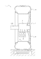
- FIG. 1 shows a schematic view schematically showing a wireless power receiving system 1 according to an embodiment of the present invention using a cross section in the tire width direction.
- the wireless power receiving system 1 of the present embodiment includes a power transmitting device 40, a power receiving device 30, and a tire / wheel assembly 3 according to an embodiment of the present invention.
- the tire / wheel assembly 3 is attached to the vehicle 2, and includes a wheel 20 having a rim portion 21 and a tire 10 according to an embodiment of the present invention attached to the rim portion 21. There is.
- the vehicle 2 is, for example, a passenger car, a truck, a bus, an agricultural vehicle (tractor or the like), a construction or construction vehicle (dump truck or the like), or the like.
- the vehicle 2 has a drive shaft 2B and a hub 2A.
- the wireless power receiving system 1 may include one or a plurality of the power transmitting device 40, the power receiving device 30, and the tire / wheel assembly 3, respectively.
- One or more power receiving devices 30 may be provided for one tire / wheel assembly 3.
- the power transmission device 40 is configured to be able to transmit electric power wirelessly.
- the power receiving device 30 is provided inside the tire / wheel assembly 3, and more specifically, in the tire width direction region corresponding to the tire 10, the power receiving device 30 is inside the tread portion 13 of the tire 10 in the tire radial direction. Have been placed.
- the power receiving device 30 is configured to receive electric power wirelessly from the power transmitting device 40 in a state where the power transmitting device 40 is located at least outside the tire 10 in the tire width direction region corresponding to the tire 10. ing.
- the power transmission device 40 includes a power transmission coil (primary coil) (hereinafter, the power transmission device 40 is also referred to as a “power transmission coil 40”).
- a power source (not shown) is connected to the power transmission device 40.
- the power transmission device 40 is installed on a road surface such as a road, or is buried so as to be located near the road surface.
- the power transmission coil 40 is configured to generate an alternating magnetic field based on an alternating current supplied from a power source (not shown).
- the power transmission device 40 wirelessly transmits electric power by generating an alternating magnetic field by the power transmission coil 40.
- the power transmission coil 40 is formed in an annular shape as a whole, and is arranged so that the axial direction of the ring is substantially perpendicular to the road surface so as to generate an alternating magnetic field toward the upper side of the road surface.
- the power transmission coil 40 is shown in a direction (directivity direction) different from the actual one.
- the power transmission coil 40 is wound around a core such as a ferrite core to form an annular shape as a whole, but the present invention is not limited to this, and any coil spring, air core coil, or any other material capable of generating an alternating magnetic field is used. It can be a coil.
- the power receiving device 30 is composed of a power receiving coil (secondary coil) (hereinafter, the power receiving device 30 is also referred to as a “power receiving coil 30”).
- the power receiving coil 30 is formed in an annular shape as a whole.
- the power receiving coil 30 is the power transmission coil 40 in a state where the tire / wheel assembly 3 is located above the power transmission device 40 (and by extension, the power transmission device 40 is located outside the tire 10 in the tire radial direction).
- the ring is arranged so that the axial direction of the ring is substantially perpendicular to the road surface so as to face the road surface.
- the axial direction of the ring of the power receiving coil 30 is, for example, substantially parallel to the tire radial direction. However, in FIG.
- the power receiving coil 30 is shown in a direction (directivity direction) different from the actual one.
- the power receiving coil 30 is wound around a core such as a ferrite core to form an annular shape as a whole, but is not limited to this, and an electromotive force is generated based on an alternating magnetic field such as a coil spring or an air core coil. It can be any coil that can be generated.
- the tire 10 is positioned on the power transmission device 40 (and by extension, when the tire 10 runs or stops on the power transmission device 40).
- the power transmission device 40 can supply power to the power reception device 30 by an electromagnetic induction method, that is, the power transmission device 40 is substantially vertically upward.
- the alternating magnetic field generated in the power receiving device 30 generates an electromotive power by electromagnetic induction, and a current flows (that is, the power receiving coil 30 receives (receives power) the power). In this way, good power reception is possible through the tire 10.
- the term "transmitting electric power by radio” does not mean only the case where the electric power transmission device 40 actually transmits electric current, but the electric power transmission device 40 acts so that the electric power receiving device 30 can receive electric power. In the present embodiment, it means that the power transmission device 40 generates an alternating magnetic field.
- the term “receives power wirelessly” by the power receiving device 30 does not mean only when the electric current is actually received, but also refers to the general case where the power receiving device 30 receives power by the action from the power transmitting device 40. Therefore, in the present embodiment, it means that an electromotive force is generated in the power receiving device 30 and a current flows.
- the power receiving device 30 Since the tread portion 13 of the tire 10 is in contact with the road surface when the power receiving device 30 receives power, the risk of an obstacle entering between the power receiving device 30 and the power transmitting device 40 is reduced, and as a result, the power receiving device 30 It is possible to improve the power receiving efficiency in wireless power supply.
- the power receiving device 30 is attached to the hub 2A of the vehicle 2, but the power receiving device 30 is not limited to this, and is within the tire / wheel assembly 3 within the tire width direction region corresponding to the tire 10 and the tire. As long as it is inside the tread portion 13 of 10 in the tire radial direction, it can be attached at any position.
- the power receiving device 30 may be attached to the drive shaft 2B of the vehicle 2, or may be attached to the rim portion 21 and arranged on the inner peripheral side or the outer peripheral side of the rim portion 21, or the tire 10. It may be attached to the inner surface of the. It is preferable that the power receiving device 30 is arranged at least within the tire width direction region corresponding to the tread portion 13 from the viewpoint of power receiving efficiency, as in the example of FIG.
- the power receiving device 30 is 1 for one tire / wheel assembly 3.
- One or more may be provided.
- the power receiving device 30 is mounted at a position where it does not rotate with the rotation of the tire 10 (for example, when it is mounted on the hub 2A as in the example of FIG. 1), the power receiving device 30 is located at a position facing the road surface. It is preferable that only one is installed.
- the power receiving device 30 is mounted at a position where it rotates with the rotation of the tire 10 (for example, when it is mounted on the drive shaft 2B, the rim portion 21, or the tire 10)
- the plurality of power receiving devices 30 are mounted on the tire circumference. It is preferable that the tires are arranged along the direction.
- the wireless power receiving system 1 further includes a power conversion circuit 32, a power storage unit 33, and a control unit 34 inside the tire / wheel assembly 3 (preferably inside the wheel 20). You may have it.
- the power conversion circuit 32 converts the AC power generated in the power receiving coil 30 into DC power, and supplies the DC power to the power storage unit 33 or another in-vehicle device included in the vehicle 2 via a conductive wire or the like.
- the power storage unit 33 stores the electric power generated in the power receiving coil 30.
- the power storage unit 33 is, for example, a capacitor, but is not limited to this, and can be any power storage device such as a storage battery.
- the control unit 34 may include one or more processors that provide processing for controlling each function of the power receiving device 30.
- the control unit 34 can be a general-purpose processor such as a CPU (Central Processing Unit) that executes a program that defines a control procedure, or a dedicated processor that specializes in processing each function.
- the control unit 34 may include a storage means for storing a program or the like, and an arbitrary means used for controlling a power receiving device 30 such as a communication means for communicating with an external electronic device by wire or wirelessly.
- the inventor of the present invention describes the frequency of power transmitted from the power transmission device 40 (and thus the frequency of the alternating current supplied from the power source to the power transmission device 40, the frequency of the alternating magnetic field transmitted from the power transmission device 40, and the power reception. It has been newly found that the power receiving efficiency can be improved by optimizing the structure of the tire 10 according to the frequency of the power received by the device 30). More specifically, the inventor of the present invention mainly uses the tire 10 when the power transmission device 40 is configured to wirelessly transmit electric power having a frequency of 1000 kHz or less (preferably 500 kHz or less).
- the tire 10 is mainly a power transmission device. It has been newly found that the power loss at the time of receiving power can be suppressed and the power receiving efficiency can be improved by minimizing the inclusion of the magnetic material in the portion located between the 40 and the power receiving device 30.
- a magnetic material for example, steel
- the inventor of the present invention mainly uses the tire 10 when the power transmission device 40 is configured to wirelessly transmit power at a frequency higher than 1000 kHz (preferably higher than 2000 kHz).
- a frequency higher than 1000 kHz preferably higher than 2000 kHz.
- the inventor of the present invention mainly uses the tire 10 when the power transmission device 40 is configured to wirelessly transmit electric power having a frequency higher than 1000 kHz (preferably higher than 2000 kHz).
- the power transmission device 40 is configured to wirelessly transmit electric power having a frequency of 1000 kHz or less (preferably 500 kHz or less) is simply “in the case of low frequency”.
- the positional relationship of each element shall be measured in a reference state in which the tire 10 is mounted on the rim portion 21 which is the applicable rim, the specified internal pressure is applied, and no load is applied. .. Further, when the tire 10 is attached to the rim portion 21 which is the applicable rim, the tire 10 is filled with the specified internal pressure, and the maximum load is applied, the width of the contact patch in contact with the road surface in the tire width direction is set to the tire contact width. The end of the contact patch in the tire width direction is called the contact patch.
- the "applicable rim” is an industrial standard effective in the area where pneumatic tires are produced and used.
- JATMA Joint Automobile Tire Association
- JATMA YEAR BOOK JATMA YEAR BOOK
- ETRTO ETRTO
- STANDARDS MANUAL Maasuring Rim
- TRA's YEAR BOOK refers to Design Rim
- the "applicable rim” includes the size described in the above-mentioned industrial standard in the future in addition to the current size.
- the size described as "FUTURE DEVELOPMENTS” in the ETRTO 2013 edition can be mentioned.
- the "specified internal pressure” means the air pressure (maximum air pressure) corresponding to the maximum load capacity of a single wheel in the applicable size and ply rating described in the above-mentioned industrial standards such as JATMA YEAR BOOK. In the case of a size not described in the above-mentioned industrial standards, it means the air pressure (maximum air pressure) corresponding to the maximum load capacity specified for each vehicle equipped with tires. Further, in the present specification, the "maximum load” means a load corresponding to the maximum load capacity of a tire of an applicable size described in the above-mentioned industrial standard, or a size not described in the above-mentioned industrial standard. Means the load corresponding to the maximum load capacity specified for each vehicle equipped with tires.
- FIG. 2 shows a cross-sectional view in the tire width direction in which the tire 10 of the present embodiment is cut along the tire width direction.
- the tire width direction means a direction parallel to the rotation axis of the tire 10.
- the tire width direction is indicated by an arrow W.
- the tire radial direction means a direction orthogonal to the rotation axis of the tire 10.
- the tire radial direction is indicated by an arrow R.
- the tire 10 is described as having a configuration symmetrical with respect to the equatorial plane CL of the tire, but the present invention is not limited to this, and the tire 10 may have a configuration asymmetrical with respect to the equatorial plane CL of the tire.
- the side close to the rotation axis of the tire 10 along the tire radial direction is referred to as “inside in the tire radial direction” or “inner peripheral side of the tire”, and the side far from the rotation axis of the tire 10 along the tire radial direction. Is referred to as “outside the tire radial direction” or “outer circumference side of the tire”.
- the side of the tire near the equatorial plane CL along the tire width direction is referred to as “inside in the tire width direction”
- the side of the tire far from the equatorial plane CL along the tire width direction is referred to as "outside in the tire width direction”.
- the tire 10 has a tread between a pair of bead portions 11, a pair of sidewall portions 12 continuous from the bead portions 11 outward in the tire radial direction, and a pair of sidewall portions 12, respectively. It has a part 13.
- the tread portion 13 is a portion in the tire width direction between the pair of ground contact ends.
- the tread portion 13 may be formed only of a non-magnetic material.
- the power receiving efficiency can be improved as compared with the case where the tread portion 13 contains a magnetic material (for example, steel).
- the tread portion 13 can receive good power regardless of the material, and specifically, it is formed of only a non-magnetic material or only a part of it is magnetic. It is good if it is made of material (the rest is made of non-magnetic material).
- the tread portion 13 is located between the power transmitting device 40 and the power receiving device 30 when receiving power (and by extension, is at a position where electric power (specifically, a magnetic field in the present embodiment) mainly passes through), the tread portion 13 is located between the power transmitting device 40 and the power receiving device 30. Optimizing the material of the unit 13 in this way greatly contributes to improving the power receiving efficiency.
- Non-magnetic materials include paramagnetic and diamagnetic materials with low magnetic permeability.
- a resin material containing a thermoplastic resin such as polyester and nylon, a thermosetting resin such as vinyl ester resin and unsaturated polyester resin, and other synthetic resins can be used.
- the resin material can further contain fibers such as glass, carbon, graphite, aramid, polyethylene, and ceramic as reinforcing fibers.
- the non-magnetic material not only resin but also any non-metal material including rubber, glass, carbon, graphite, aramid, polyethylene, ceramic and the like can be used.
- non-magnetic material a metal material containing a paramagnetic material such as aluminum or a diamagnetic material such as copper can be used.
- the magnetic material is a material exhibiting ferromagnetism (ferromagnet), and corresponds to, for example, steel.
- the tire 10 has a carcass 14.
- the carcass 14 extends toroidally between the pair of bead cores 11A and forms the skeleton of the tire.
- the end side of the carcass 14 is locked to the bead core 11A.
- the carcass 14 has a carcass main body portion 14A arranged between the bead cores 11A, and a carcass folding portion 14B that is folded around the bead core 11A from the inside in the tire width direction to the outside in the tire width direction. ing.
- the length of the carcass folding portion 14B can be arbitrary.
- the carcass 14 may have a structure that does not have the carcass folding portion 14B, or a structure in which the carcass folding portion 14B is wound around the bead core 11A.
- the carcass 14 can be composed of one or more carcass layers (one in the example of FIG. 2).
- the carcass 14 may be composed of two carcass layers arranged so as to be laminated in the tire radial direction on the equatorial plane CL of the tire.
- each carcass layer contains one or a plurality of carcass cords 14c and a coated rubber 14r covering the carcass cords 14c.
- the carcass cord 14c can be formed of monofilament or stranded wire.
- the carcass cord 14c may be made of a non-magnetic material.
- the power receiving efficiency can be improved as compared with the case where the carcass cord is made of a magnetic material (for example, steel).
- the carcass cord 14c only a part of the carcass 14 including the portion constituting the tread portion 13 may be formed of a non-magnetic material, and the other portion may be formed of a magnetic material.
- the carcass cord 14c can receive good power regardless of whether it is made of a non-magnetic material or a magnetic material. Since the portion of the carcass 14 that mainly constitutes the tread portion 13 is located between the power transmitting device 40 and the power receiving device 30 when receiving power, it is possible to make the material of the carcass 14 suitable in this way for power receiving efficiency.
- the carcass cord 14c is made of a non-magnetic material
- the carcass cord 14c may be composed of any resin material, such as polyester, nylon, rayon, and aramid, as well as any other non-magnetic material. it can.
- the carcass 14 may have a radial structure or a bias structure.
- the carcass 14 may be integrally formed of the above-mentioned resin material or the like without using the carcass cord 14c. Further, in the carcass 14, only a part including a portion constituting the tread portion 13 may be formed of a non-magnetic material, and the other portion may be formed including a magnetic material.
- a belt 15 for reinforcing the tread portion 13 is provided on the outer side of the tread portion 13 in the tire radial direction of the carcass 14.
- a tread rubber is provided on the outer peripheral side of the belt 15 in the tire radial direction.
- the belt 15 can be composed of, for example, one or more (two in the example of FIG. 2) belt layers 15a and 15b laminated in the tire radial direction.
- each of the belt layers 15a and 15b includes one or a plurality of belt cords 15c and a covering rubber 15r that covers the belt cords 15c.
- the belt cord 15c can be formed of a monofilament or a stranded wire.
- the belt cord 15c may be made of a non-magnetic material.
- the power receiving efficiency can be improved as compared with the case where the belt cord 15c is made of a magnetic material (for example, steel).
- the belt cord 15c only a part of the belt 15 including the portion constituting the tread portion 13 may be formed of a non-magnetic material, and the other portion may be formed of a magnetic material.
- the belt cord 15c can receive good power regardless of whether it is made of a non-magnetic material or a magnetic material.
- the belt 15c is made of a non-magnetic material
- the belt cord 15c may be made of any resin material, such as polyester, nylon, rayon, and aramid, as well as any other non-magnetic material. it can.
- the belt 15 may be integrally formed of the above-mentioned resin material or the like without using the belt cord 15c. Further, in the belt 15, only a part including a portion constituting the tread portion 13 may be formed of a non-magnetic material, and the other portion may be formed including a magnetic material.
- the pair of bead portions 11 have a bead core 11A and a bead filler 11B, respectively.
- the bead core 11A includes a plurality of bead wires 11c whose periphery is covered with rubber.
- the bead wire 11c can be formed of a monofilament or a stranded wire.
- the bead filler 11B is made of rubber or the like and is located outside the bead core 11A in the tire radial direction. In the present embodiment, the bead filler 11B has a thickness decreasing toward the outer side in the tire radial direction.
- the tire 10 may have a structure in which the bead filler 11B is not provided.
- the bead portion 11 is configured to be in contact with the rim on the inner side in the tire radial direction and the outer side in the tire width direction when the tire 10 is mounted on the rim. Since the bead portion 11 tends to be located outside the power transmitting device 40 and the power receiving device 30 in the tire width direction when receiving power, the bead portion 11 is a portion having less influence on the power receiving efficiency than the tread portion 13. Therefore, at low frequencies, the bead wire 11c can receive good power whether it is made of a non-magnetic material or a magnetic material (eg, steel). Further, in the case of high frequency, the bead wire 11c can receive good power regardless of whether it is made of a non-magnetic material or a magnetic material. When the bead wire 11c is made of a non-magnetic material, the bead wire 11c can be made of any resin material such as polyester, nylon, rayon, and aramid, as well as any other non-magnetic material.
- the sidewall portion 12 tends to be located outside the power transmitting device 40 and the power receiving device 30 in the tire width direction when receiving power, the sidewall portion 12 has less influence on the power receiving efficiency than the tread portion 13. Therefore, in the case of a low frequency, good power reception is possible even if the sidewall portion 12 is formed only of a non-magnetic material (for example, rubber) or is formed including a magnetic material.
- the magnetic field transmitted from the power transmitting device 40 to the power receiving device 30 may be a metal or other magnetic field that may exist outside the sidewall portion 12 in the tire width direction. It is possible to suppress the attenuation due to the influence of the above, and the power receiving efficiency can be improved.
- the sidewall portion 12 is formed only of a non-magnetic material (for example, rubber) or is formed including a magnetic material.
- a non-magnetic material for example, rubber
- a magnetic material that can be contained in the sidewall portion 12 include ferrite.
- the tire 10 has an inner liner 16.
- the inner liner 16 is arranged so as to cover the inner wall surface of the tire 10.
- the inner liner 16 can be composed of a plurality of inner liner layers laminated in the tire radial direction on the equatorial plane CL of the tire.
- the inner liner 16 is made of, for example, a butyl rubber having low air permeability.
- Butyl rubber includes, for example, butyl rubber and a halogenated butyl rubber which is a derivative thereof.
- the inner liner 16 is not limited to the butyl rubber, and can be composed of other rubber compositions, resins, or elastomers.
- FIG. 3 shows a cross-sectional view in the tire width direction in which the wheel 20 of the present embodiment is cut along the tire width direction.
- the inventor of the present invention describes the frequency of power transmitted from the power transmission device 40 (and thus the frequency of the alternating current supplied from the power source to the power transmission device 40, the frequency of the alternating magnetic field transmitted from the power transmission device 40, and the power reception. It has been newly found that the power receiving efficiency can be improved by optimizing the structure of the wheel 20 according to the frequency of the power received by the device 30). More specifically, the inventor of the present invention mainly uses the wheel 20 in the case of low frequency when the power receiving device 30 is arranged inside the wheel 20 in the radial direction as in the example of FIG.
- the inventor of the present invention receives power by making the wheel 20 contain as little magnetic material as possible in the portion mainly located between the power transmission device 40 and the power reception device 30 in the case of low frequency. It was newly found that the power loss at the time of the above can be suppressed and the power receiving efficiency can be improved. Further, the inventor of the present invention states that when the power receiving device 30 is arranged inside the tire radial direction with respect to the wheel 20 as in the example of FIG.
- the wheel 20 is mainly used as the power transmitting device 40. It has been newly added that even if a magnetic material (for example, steel) is contained in the portion located between the power receiving device 30 and the power receiving device 30, there is no power loss during power receiving, almost as in the case where the magnetic material is not contained. Found in. Then, the inventor of the present invention, in the case of high frequency, receives power regardless of whether the wheel 20 contains a magnetic material or not in a portion mainly located between the power transmitting device 40 and the power receiving device 30. It was newly found that the power loss of the power transmission can be suppressed and good power reception becomes possible. The configuration of the wheel 20 described below is based on such findings.
- a magnetic material for example, steel
- tire radial direction refers to the tire radial direction and the tire width when the tire 10 is assembled to the wheel 20. Refers to the direction and the tire circumference direction, respectively.
- the wheel 20 has a cylindrical rim portion 21 and a disc portion 22 provided inside the rim portion 21 in the tire radial direction and supported and fixed to the hub 2A of the vehicle 2. There is.
- the wheel 20 accommodates the power receiving device 30 inside the rim portion 21 in the tire radial direction, that is, in a space surrounded by the rim portion 21 and the disc portion 22.
- the rim portion 21 has a pair of flanges 23 (inner flange 23A, outer flange 23B), a pair of bead seats 24 (inner bead seat 24A, outer bead seat 24B), and wells 25 from the outside in the tire width direction. , Are provided.
- the bead portion 11 of the tire 10 is attached to the bead seat 24.
- the flange 23 extends from the bead seat 24 outward in the tire radial direction and outward in the tire width direction in order to support the bead portion 11 of the tire 10 from the side surface.
- the well 25 has a concave shape inward in the tire radial direction between the pair of bead seats 24 in order to facilitate the attachment / detachment of the tire.
- the well 25 has an inclined surface that goes down from the boundary with the bead sheet 24 to the bottom surface of the well 25 toward the inside in the tire width direction toward the inside in the tire radial direction.
- the bead seat 24 is provided with a pair of humps 26 (inner hump 26A, outer hump 26B) inside in the tire width direction.
- the hump 26 projects outward in the tire radial direction in order to prevent the bead portion 11 of the tire 10 from falling into the well 25.
- the rim portion 21 may be partially or wholly made of a non-magnetic material. As a result, the power receiving efficiency can be improved as compared with the case where the rim portion 21 is formed only of a magnetic material (for example, steel).
- the rim portion 21 can receive good power regardless of whether it is made of a non-magnetic material or a magnetic material.
- the rim portion 21 tends to be located between the power transmitting device 40 and the power receiving device 30 when receiving power when the power receiving device 30 is arranged inside the wheel 20 in the tire radial direction as in the example of FIG. Therefore, making the material of the rim portion 21 suitable in this way greatly contributes to the improvement of the power receiving efficiency.
- a resin material is preferable as such a non-magnetic material.
- a portion of the tire 10 facing the tread portion 13 is formed of a non-magnetic material, and a portion outside the tire width direction is a magnetic material (for example, steel). ) May be formed.
- a magnetic material for example, steel
- the rim portion 21 of the wheel 20 is further provided with a valve 27 for filling the cavity of the tire 10 with a gas such as air when the tire 10 is mounted.
- the disc portion 22 is provided with an annular mounting portion 22A forming an inner end portion in the radial direction, and a plurality of spokes 22B extending outward in the tire radial direction from the mounting portion 22A.
- the mounting portion 22A is a portion to be coupled and fixed to the hub 2A of the vehicle 2, and has a mounting hole penetrating in the tire width direction for inserting a bolt or the like for fixing the hub 2A and the mounting portion 22A. ..
- the tire radial outer end of the spoke 22B is integrally coupled to the end of the tire radial inner surface of the rim portion 21. When receiving power, the disk portion 22 tends to be located outside the power transmitting device 40 and the power receiving device 30 in the tire width direction.
- the disk portion 22 can receive good power even if it is formed of only a non-magnetic material or is formed of containing a magnetic material.
- the magnetic field transmitted from the power transmitting device 40 to the power receiving device 30 is affected by metal and other magnetic fields that may exist outside the disc portion 22 in the tire width direction. It is possible to suppress the attenuation due to the above and improve the power receiving efficiency.
- the magnetic material that can form a part or all of the disk portion 22 include steel and ferrite.
- a resin material is suitable as the non-magnetic material that can form a part or all of the disk portion 22, for example.
- the resin material has the advantage of being lightweight.
- the disc portion 22 of the wheel 20 is provided with a wheel cover 28 that covers the outside of the spokes 22B in the tire width direction.
- the wheel cover 28 tends to be located outside the power transmitting device 40 and the power receiving device 30 in the tire width direction when receiving power. Therefore, in the case of low frequencies, the wheel cover 28 can receive good power even if it is made of only a non-magnetic material or is made of a magnetic material.
- the wheel cover 28 is formed to include a magnetic material, the magnetic field transmitted from the power transmitting device 40 to the power receiving device 30 is affected by metals and other magnetic fields that may exist outside the wheel cover 28 in the tire width direction. It is possible to suppress the attenuation due to the above and improve the power receiving efficiency.
- the wheel cover 28 can receive good power even if it is made of only a non-magnetic material or is made of a magnetic material.
- the magnetic material that can form a part or all of the wheel cover 28 include steel and ferrite.
- a resin material is suitable as the non-magnetic material that can form a part or all of the wheel cover 28, for example.
- FIG. 4 shows a schematic view schematically showing a modified example of the wireless power receiving system 1 according to the embodiment of the present invention using a cross section in the tire width direction.
- a modification of the wireless power receiving system 1 is different from the wireless power receiving system 1 shown in FIG. 1 in that it further includes an in-wheel motor 4 housed in a wheel 20.
- the members and parts common to the wireless power receiving system 1 shown in FIG. 1 are designated by the same reference numerals, and their description will be omitted.
- the in-wheel motor 4 is integrated with the hub and installed in the wheel 20, and is configured to rotationally drive the tire 10 and the wheel 20. As shown in FIG. 4, the in-wheel motor 4 may be partially located outside the wheel 20 in the tire width direction in a state of being attached to the wheel 20.
- the power receiving device 30 is attached to the in-wheel motor 4.
- the in-wheel motor 4 is attached to a drive shaft 2B of a vehicle 2 such as an automobile (the whole is not shown).
- the power receiving device 30 is inside the tire / wheel assembly 3 within the tire width direction region corresponding to the tire 10 and inside the tire radial direction with respect to the tread portion 13 of the tire 10. It can be installed in any position.
- the specific mounting position of the power receiving device 30 may be, for example, mounted on the outer side of the rim portion 21 in the tire radial direction.
- the wheel 20 may be made of either a magnetic material or a non-magnetic material.
- the power receiving device 30 may be attached to the inside of the rim portion 21 in the tire radial direction.
- it is desirable that the wheel 20 is made of a non-magnetic material.
- the power conversion circuit 32 converts the power generated in the power receiving coil 30 into DC power, and supplies DC power to the power storage unit 33 or the in-wheel motor 4 via a conductive wire or the like.
- the power storage unit 33 stores the electric power generated in the power receiving coil 30.
- the power storage unit 33 is, for example, a capacitor, but is not limited to this, and can be any power storage device such as a storage battery.
- the power storage unit 33 is a capacitor, charging / discharging can be performed in a shorter time than that of a storage battery. Therefore, in a situation where the power storage unit 33, which is a capacitor, is required to have high responsiveness such as accumulating the electric power generated in the power receiving coil 30 when the vehicle 2 travels on the power transmission device 40 provided on the road. It is advantageous. With such a configuration, the electric power received by the power receiving device 30 can be used for the rotational drive of the in-wheel motor 4.
- the wireless power receiving system, tire / wheel assembly, and tire of the present invention are not limited to those of the above-mentioned examples, and various modifications are possible.
- the power supply from the power transmitting device 40 to the power receiving device 30 may be performed by any method other than the electromagnetic induction method.
- the power supply from the power transmitting device 40 to the power receiving device 30 may be performed by an electric field coupling method.
- the tire / wheel assembly 3 and the tire 10 can be attached to any moving body with tires (for example, a motorcycle, a wheelchair, a cart, etc.) other than the vehicle 2.
- the tire 10 may not have the carcass 14 and / or the belt 15.
- air is filled between the tire 10 and the rim portion 21, but this is not the case.
- a gas such as nitrogen can be filled between the tire 10 and the rim portion 21.
- the space between the tire 10 and the rim portion 21 can be filled with an arbitrary fluid including not only a gas but also a liquid, a gel-like substance, a powder or granular material, or the like.
- the tire 10 has been described as being a tubeless tire provided with the inner liner 16, but this is not the case.
- the tire 10 may be a tube type tire including a tube.
- the tire 10 may be an airless tire which is formed in whole or in part by the above-mentioned resin material and is used without filling the tire 10 with gas.
- the ratio SW / OD of the cross-sectional width SW of the tire 10 to the outer diameter OD is 0.26 or less.
- the cross-sectional width SW of the tire 10 is 165 (mm) or more, the cross-sectional width SW (mm) and the outer diameter OD (mm) of the tire 10 are OD (mm) ⁇ 2.135 x SW (mm) + 282.3 (mm) (Hereinafter referred to as "relational expression (1)”) It is preferable to satisfy.
- the cross-sectional width SW of the tire 10 becomes relatively small with respect to the outer diameter OD of the tire 10, the air resistance is reduced, and the cross-sectional width is narrow. Therefore, it is possible to secure a vehicle space, and in particular, it is possible to secure an installation space for drive parts near the inside of the tire mounted on the vehicle.
- the outer diameter OD of the tire 10 becomes relatively large with respect to the cross-sectional width SW of the tire 10, the rolling resistance is reduced, and the tire 10 As the diameter of the tire increases, the wheel shaft becomes taller and the space under the floor is expanded, so that it is possible to secure a space for a vehicle trunk and the like and a space for installing drive parts.
- the tire 10 has a cross-sectional width SW (mm) and an outer diameter OD (mm) of the tire 10.
- the outer diameter OD of the tire becomes relatively large with respect to the cross-sectional width SW of the tire 10, the rolling resistance is reduced, and the wheel is increased by increasing the diameter of the tire 10. Since the shaft is raised and the space under the floor is expanded, it is possible to secure space for the trunk of the vehicle and installation space for driving parts. As described above, by satisfying the above relational expression (2), it is possible to achieve low fuel consumption with respect to the supplied electric energy, and it is also possible to secure a large vehicle space.
- the tire 10 preferably satisfies the ratio SW / OD and / or the relational expression (2), or preferably satisfies the relational expression (1) and / or the relational expression (2). ..
- the tire 10 preferably satisfies the ratio SW / OD and / or the relational expression (2) when the internal pressure is 250 kPa or more, or the relational expression (1) and / Alternatively, it is preferable to satisfy the relational expression (2).
- the tire 10 is preferably used at an internal pressure of 250 kPa or more.
- the tire 10 satisfies the ratio SW / OD and / or the relational expression (2) when the internal pressure is 250 kPa or more, or the relational expression (1) and / or the relational expression (2). ) Is satisfied.
- both the rolling resistance value of the tire and the weight of the tire can be reduced. Therefore, both power feeding efficiency and fuel efficiency can be suitably achieved.
- the tire width direction cross-sectional area S1 of the bead filler 11B is 1 time or more and 8 times or less the tire width direction cross-sectional area S2 of the bead core 11A.
- both power supply efficiency and fuel efficiency can be suitably achieved.
- the total volume of the bead cores inside and outside the width direction of the carcass is defined as S2.
- the volume of the bead filler which is a high-rigidity member, can be reduced, the vertical spring constant of the tire can be reduced, and the riding comfort can be improved. It is also possible to reduce the weight of the bead filler and reduce the weight of the tire, and therefore the rolling resistance value of the tire is further reduced.
- the tension rigidity of the belt is high and the tension rigidity of the tire side portion is low as compared with the belt.
- the effect of reducing the vertical spring constant by setting the cross-sectional area S1 of the bead filler within a predetermined range becomes very high.
- the tire width direction cross-sectional area S1 of the bead filler 11B is more than eight times the tire width direction cross-sectional area S2 of the bead core 11A, the volume of the bead filler, which is a high-rigidity member, becomes large, and the vertical spring coefficient of the tire becomes sufficient. It is not reduced and there is a risk that the ride quality will be reduced.
- the rigidity of the bead portion is significantly reduced, the lateral spring constant is excessively reduced, and the steering is stable. There is a risk that the sex cannot be ensured.
- the tire section height SH is 1 / of the difference between the outer diameter of the tire and the rim diameter in the no-load state when the tire is incorporated in the rim and the internal pressure specified for each vehicle to which the tire is mounted is applied. It shall refer to 2.
- the height BFH (FIG. 2) of the bead filler 11B in the tire radial direction is preferably 45 mm or less. As a result, both power supply efficiency and fuel efficiency can be suitably achieved.
- the tire 10 has a gauge Ts (FIG. 2) of the sidewall portion 12 at the maximum tire width portion and a bead width Tb (width of the bead portion 11 in the tire width direction) at the center position in the tire radial direction of the bead core 11A.
- Ts gauge of the sidewall portion 12 at the maximum tire width portion
- Tb width of the bead portion 11 in the tire width direction
- the ratio Ts / Tb with FIG. 2) is 15% or more and 60% or less.
- the “maximum tire width portion” refers to the maximum width position in the cross section in the tire width direction when the tire is mounted on the rim and is in a no-load state.
- Gauge Ts is the total thickness of all members such as rubber, reinforcing members, and inner liner. Further, in the case of a structure in which the bead core is divided into a plurality of small bead cores by a carcass, the distance between the innermost end and the outermost end in the width direction of all the small bead cores may be Tb. By setting the ratio Ts / Tb to the above range, it is possible to appropriately reduce the rigidity in the maximum width portion of the tire having a large bending deformation under a tire load, reduce the longitudinal spring coefficient, and improve the riding comfort. ..
- the ratio Ts / Tb exceeds 60%, the gauge of the sidewall portion 12 in the maximum tire width portion becomes large, the rigidity of the sidewall portion 12 becomes high, and the vertical spring coefficient may become high. is there. On the other hand, if the ratio Ts / Tb is less than 15%, the lateral spring constant may be too low to ensure steering stability.
- the tire 10 preferably has a gauge Ts (FIG. 2) of the sidewall portion 12 at the maximum tire width portion of 1.5 mm or more.
- Ts gauge Ts
- both power supply efficiency and fuel efficiency can be suitably achieved.
- the thickness By setting the thickness to 1.5 mm or more, it is possible to maintain an appropriate rigidity in the maximum tire width portion, suppress a decrease in the lateral spring coefficient, and further secure steering stability.
- the tire 10 preferably has a bead core 11A having a diameter Tbc (maximum width of the bead core in the tire width direction, FIG. 2) of 3 mm or more and 16 mm or less.
- Tbc maximum width of the bead core in the tire width direction, FIG. 2
- both power supply efficiency and fuel efficiency can be suitably achieved.
- the tire 10 preferably has a contact area of 8000 mm 2 or more when the maximum load specified for each vehicle to which the tire is mounted is applied.
- the tire axial force can be secured to improve the stability and safety of the vehicle.
- the tire 10 preferably has a belt cord 15c with a Young's modulus of 40,000 MPa or more.
- the carcass structure and belt rigidity can be optimized, and the strength of the tire that can be used even at a high internal pressure can be secured.
- both power supply efficiency and fuel efficiency can be suitably achieved.
- the tire 10 preferably has an inner liner 16 having a thickness of 0.6 mm or more. This makes it possible to suppress air leakage in a high internal pressure state. In addition, both power supply efficiency and fuel efficiency can be suitably achieved.
- the tire 10 has a ratio Ts / Tc of the gauge Ts (FIG. 2) of the sidewall portion 12 at the maximum width portion of the tire and the diameter Tc of the carcass cord (FIG. 2) of 4 or more and 12 or less. It is preferable to have it. As a result, both power supply efficiency and fuel efficiency can be suitably achieved.
- the ratio Ts / Tc By setting the ratio Ts / Tc to the above range, it is possible to appropriately reduce the rigidity in the maximum width portion of the tire having a large bending deformation under a tire load, reduce the longitudinal spring coefficient, and improve the riding comfort. ..
- the gauge of the sidewall portion 4 in the maximum tire width portion becomes large, the rigidity of this portion becomes high, and the vertical spring coefficient may become high.
- the ratio Ts / Tc is less than 4, the lateral spring constant may be too low to ensure steering stability.
- the distance in the tire width direction from the surface of the carcass cord 14c to the outer surface of the tire in the maximum width portion of the tire is Ta (FIG. 2)
- the distance Ta and the diameter Tc of the carcass cord is preferably 2 or more and 8 or less.
- both power supply efficiency and fuel efficiency can be suitably achieved.
- Ta (FIG. 2) refers to the distance in the tire width direction from the surface of the outermost carcass cord 14c in the width direction to the outer surface of the tire in the tire maximum width portion. That is, when the carcass folded portion 14B extends radially outward from the maximum tire width portion, the distance in the tire width direction from the surface of the carcass cord 14c of the portion forming the carcass folded portion 14B to the outer surface of the tire is set to Ta. ..
- the tire 10 preferably has a carcass cord 14c having a diameter Tc (FIG. 2) of 0.2 mm or more and 1.2 mm or less.
- Tc diameter of 0.2 mm or more and 1.2 mm or less.
- both power supply efficiency and fuel efficiency can be suitably achieved.
- the gauge Ts of the sidewall portion with respect to the carcass cord diameter Tc can be reduced to reduce the vertical spring coefficient, while by setting it to 0.2 mm or more, the carcass cord diameter can be reduced. It is possible to secure the gauge Ts of the sidewall portion with respect to Tc and increase the lateral spring constant to ensure steering stability.
- the wireless power receiving system, tire / wheel assembly, and tire of the present invention can be suitably used for any moving body with tires, such as a vehicle, a motorcycle, a wheelchair, and a cart.
- a vehicle examples include a passenger car, a truck, a bus, an agricultural vehicle (tractor, etc.), a construction vehicle or a construction vehicle (dump truck, etc.), and the passenger car is particularly suitable.
Landscapes
- Engineering & Computer Science (AREA)
- Power Engineering (AREA)
- Mechanical Engineering (AREA)
- Transportation (AREA)
- Computer Networks & Wireless Communication (AREA)
- Tires In General (AREA)
- Charge And Discharge Circuits For Batteries Or The Like (AREA)
- Current-Collector Devices For Electrically Propelled Vehicles (AREA)
- Electric Propulsion And Braking For Vehicles (AREA)
Abstract
La présente invention porte sur un système de réception d'énergie sans fil comprenant un dispositif de transmission d'énergie, un dispositif de réception d'énergie, une roue dotée d'une section jante et un pneu monté sur la section jante. Le pneu comporte une tringle et un bourrage sur tringle ; une surface de section transversale dans le sens de la largeur du pneu (S1) du bourrage sur tringle équivaut à au minimum une fois et au maximum huit fois une surface de section transversale dans le sens de la largeur du pneu (S2) de la tringle ; le dispositif de transmission d'énergie est conçu de façon à pouvoir transmettre sans fil de l'énergie ayant une fréquence de 1 000 kHz ou moins ; le dispositif de réception d'énergie est disposé davantage vers l'intérieur dans la direction radiale du pneu qu'une section bande de roulement du pneu ; le dispositif de réception d'énergie est conçu de façon à recevoir de l'énergie sans fil en provenance du dispositif de transmission d'énergie dans un état dans lequel le dispositif de transmission d'énergie est situé plus loin vers l'extérieur dans la direction radiale du pneu que le pneu ; et le pneu est tel que la section bande de roulement est formée à l'aide d'un matériau non magnétique.
Priority Applications (3)
| Application Number | Priority Date | Filing Date | Title |
|---|---|---|---|
| EP20843235.1A EP4005828A4 (fr) | 2019-07-25 | 2020-07-22 | Système de réception d'énergie sans fil, ensemble pneu/roue, et pneu |
| US17/597,669 US12311703B2 (en) | 2019-07-25 | 2020-07-22 | Wireless power reception system, tire/wheel assembly, and tire |
| CN202080052629.4A CN114144330B (zh) | 2019-07-25 | 2020-07-22 | 无线受电系统、轮胎/轮组件和轮胎 |
Applications Claiming Priority (2)
| Application Number | Priority Date | Filing Date | Title |
|---|---|---|---|
| JP2019-137240 | 2019-07-25 | ||
| JP2019137240A JP7365804B2 (ja) | 2019-07-25 | 2019-07-25 | 無線受電システム、タイヤ・ホイール組立体、及び、タイヤ |
Publications (1)
| Publication Number | Publication Date |
|---|---|
| WO2021015257A1 true WO2021015257A1 (fr) | 2021-01-28 |
Family
ID=74194228
Family Applications (1)
| Application Number | Title | Priority Date | Filing Date |
|---|---|---|---|
| PCT/JP2020/028511 Ceased WO2021015257A1 (fr) | 2019-07-25 | 2020-07-22 | Système de réception d'énergie sans fil, ensemble pneu/roue, et pneu |
Country Status (5)
| Country | Link |
|---|---|
| US (1) | US12311703B2 (fr) |
| EP (1) | EP4005828A4 (fr) |
| JP (2) | JP7365804B2 (fr) |
| CN (1) | CN114144330B (fr) |
| WO (1) | WO2021015257A1 (fr) |
Families Citing this family (2)
| Publication number | Priority date | Publication date | Assignee | Title |
|---|---|---|---|---|
| JP2021095096A (ja) * | 2019-12-19 | 2021-06-24 | 株式会社ブリヂストン | タイヤ・ホイール組立体 |
| JP2025018230A (ja) | 2023-07-26 | 2025-02-06 | ルネサスエレクトロニクス株式会社 | 半導体装置の製造方法 |
Citations (9)
| Publication number | Priority date | Publication date | Assignee | Title |
|---|---|---|---|---|
| JP2002219914A (ja) * | 2001-01-29 | 2002-08-06 | Toyo Tire & Rubber Co Ltd | タイヤ回転数検出装置及びタイヤ製造方法及びタイヤ |
| WO2009008502A1 (fr) * | 2007-07-11 | 2009-01-15 | Kabushiki Kaisha Bridgestone | Procédé d'évaluation de l'usure d'un pneu |
| JP2009106136A (ja) * | 2007-10-25 | 2009-05-14 | Toyota Motor Corp | 電動車両および車両用給電装置 |
| JP2012110211A (ja) * | 2010-10-27 | 2012-06-07 | Equos Research Co Ltd | 電力伝送システム |
| JP2013063765A (ja) * | 2011-08-26 | 2013-04-11 | Bridgestone Corp | 乗用車用空気入りラジアルタイヤ及びその使用方法 |
| JP2013104792A (ja) * | 2011-11-14 | 2013-05-30 | Bridgestone Corp | トレッド厚さ測定方法 |
| JP2014195350A (ja) * | 2013-03-28 | 2014-10-09 | Ryutech Co Ltd | 電動車両給電システム |
| JP2019137240A (ja) | 2018-02-12 | 2019-08-22 | トヨタ自動車株式会社 | ステアリングアシストシステム |
| WO2019244349A1 (fr) * | 2018-06-22 | 2019-12-26 | 横浜ゴム株式会社 | Pneu et feuille d'assemblage |
Family Cites Families (19)
| Publication number | Priority date | Publication date | Assignee | Title |
|---|---|---|---|---|
| US4316637A (en) * | 1978-08-04 | 1982-02-23 | Reynolds Metals Company | Multi-styled aluminum wheel |
| JPH08126106A (ja) * | 1994-10-18 | 1996-05-17 | Sumitomo Electric Ind Ltd | 移動体用誘導給電装置 |
| US6470933B1 (en) * | 1998-03-09 | 2002-10-29 | Pirelli Pneumatici S.P.A. | Tire containing at least part of an electrical current generator intended for the supply of sensors and/or other electrical devices present within the tire, and method for manufacture the said tire |
| JP4213028B2 (ja) * | 2003-12-22 | 2009-01-21 | 株式会社ブリヂストン | インホイールモータシステム |
| KR100944113B1 (ko) * | 2009-02-27 | 2010-02-24 | 한국과학기술원 | 전기자동차용 전원공급 시스템 및 방법 |
| CN102427960B (zh) * | 2009-05-11 | 2015-05-06 | 皇家飞利浦电子股份有限公司 | 用于轮胎内无线传感器系统的感应功率传输的系统和方法 |
| US20110031047A1 (en) * | 2009-08-04 | 2011-02-10 | Tarr Energy Group, Llc | In-motion inductive charging system having a wheel-mounted secondary coil |
| EP2487050B1 (fr) | 2009-10-08 | 2014-09-10 | Bridgestone Corporation | Bandage pneumatique |
| EP2516204A2 (fr) * | 2009-12-24 | 2012-10-31 | Rusk Intellectual Reserve AG | Véhicule électrique et disposition d'alimentation électrique lui étant destinée |
| JP5685851B2 (ja) | 2010-08-02 | 2015-03-18 | 横浜ゴム株式会社 | 空気入りラジアルタイヤ |
| EP2455253A3 (fr) | 2010-10-27 | 2012-09-12 | Equos Research Co., Ltd. | Système de transmission d'alimentation électrique et antenne |
| US20120217819A1 (en) * | 2010-10-27 | 2012-08-30 | Equos Research Co., Ltd. | Electric power transmission system and antenna |
| KR101842308B1 (ko) * | 2010-10-29 | 2018-03-26 | 퀄컴 인코포레이티드 | 커플링된 기생 공진기들을 통한 무선 에너지 전송 |
| US20150020943A1 (en) * | 2013-07-22 | 2015-01-22 | Bridgestone Americas Tire Operations, Llc | Low-Metal Tire |
| JP6480698B2 (ja) | 2014-10-03 | 2019-03-13 | 株式会社ブリヂストン | ランフラットタイヤ |
| JP6480699B2 (ja) | 2014-10-03 | 2019-03-13 | 株式会社ブリヂストン | ランフラットタイヤ |
| CN104356733A (zh) * | 2014-10-26 | 2015-02-18 | 刘跃进 | 一种导电性路标漆及可导电、可导磁、可驱动型电磁轮胎 |
| US9964415B2 (en) * | 2015-11-13 | 2018-05-08 | Nio Usa, Inc. | Tracking power consumption and payment |
| JP6761962B2 (ja) | 2016-10-21 | 2020-09-30 | パナソニックIpマネジメント株式会社 | 移動体および無線電力伝送システム |
-
2019
- 2019-07-25 JP JP2019137240A patent/JP7365804B2/ja active Active
-
2020
- 2020-07-22 CN CN202080052629.4A patent/CN114144330B/zh active Active
- 2020-07-22 WO PCT/JP2020/028511 patent/WO2021015257A1/fr not_active Ceased
- 2020-07-22 EP EP20843235.1A patent/EP4005828A4/fr active Pending
- 2020-07-22 US US17/597,669 patent/US12311703B2/en active Active
-
2023
- 2023-06-12 JP JP2023096485A patent/JP7574361B2/ja active Active
Patent Citations (9)
| Publication number | Priority date | Publication date | Assignee | Title |
|---|---|---|---|---|
| JP2002219914A (ja) * | 2001-01-29 | 2002-08-06 | Toyo Tire & Rubber Co Ltd | タイヤ回転数検出装置及びタイヤ製造方法及びタイヤ |
| WO2009008502A1 (fr) * | 2007-07-11 | 2009-01-15 | Kabushiki Kaisha Bridgestone | Procédé d'évaluation de l'usure d'un pneu |
| JP2009106136A (ja) * | 2007-10-25 | 2009-05-14 | Toyota Motor Corp | 電動車両および車両用給電装置 |
| JP2012110211A (ja) * | 2010-10-27 | 2012-06-07 | Equos Research Co Ltd | 電力伝送システム |
| JP2013063765A (ja) * | 2011-08-26 | 2013-04-11 | Bridgestone Corp | 乗用車用空気入りラジアルタイヤ及びその使用方法 |
| JP2013104792A (ja) * | 2011-11-14 | 2013-05-30 | Bridgestone Corp | トレッド厚さ測定方法 |
| JP2014195350A (ja) * | 2013-03-28 | 2014-10-09 | Ryutech Co Ltd | 電動車両給電システム |
| JP2019137240A (ja) | 2018-02-12 | 2019-08-22 | トヨタ自動車株式会社 | ステアリングアシストシステム |
| WO2019244349A1 (fr) * | 2018-06-22 | 2019-12-26 | 横浜ゴム株式会社 | Pneu et feuille d'assemblage |
Non-Patent Citations (3)
| Title |
|---|
| "JATMA YEAR BOOK" |
| JAPAN AUTOMOBILE TYRE MANUFACTURERS ASSOCIATION (JATMA: "STANDARDS MANUAL of the ETRTO", 2013, article "FUTURE DEVELOPMENTS" |
| See also references of EP4005828A4 |
Also Published As
| Publication number | Publication date |
|---|---|
| US20220250418A1 (en) | 2022-08-11 |
| EP4005828A1 (fr) | 2022-06-01 |
| JP7574361B2 (ja) | 2024-10-28 |
| JP2021022991A (ja) | 2021-02-18 |
| US12311703B2 (en) | 2025-05-27 |
| EP4005828A4 (fr) | 2023-08-23 |
| JP2023121756A (ja) | 2023-08-31 |
| JP7365804B2 (ja) | 2023-10-20 |
| CN114144330B (zh) | 2024-07-30 |
| CN114144330A (zh) | 2022-03-04 |
Similar Documents
| Publication | Publication Date | Title |
|---|---|---|
| WO2021070557A1 (fr) | Ensemble pneu/roue | |
| JP7574361B2 (ja) | 無線受電システム、タイヤ・ホイール組立体、及び、タイヤ | |
| JP2021059308A (ja) | タイヤ・ホイール組立体 | |
| JP2021059307A (ja) | タイヤ・ホイール組立体 | |
| US12420598B2 (en) | Tire-wheel assembly, tire, and wireless power receiving system | |
| WO2021124598A1 (fr) | Ensemble pneumatique/roue | |
| JP2021022624A (ja) | タイヤ・ホイール組立体、無線受電システム、及びタイヤ | |
| JP2021059305A (ja) | タイヤ・ホイール組立体 | |
| JP2021059304A (ja) | タイヤ・ホイール組立体 | |
| JP2021098386A (ja) | タイヤ・ホイール組立体 | |
| JP2021098381A (ja) | タイヤ・ホイール組立体 | |
| JP2021059309A (ja) | タイヤ・ホイール組立体 | |
| JP2021020512A (ja) | タイヤ・ホイール組立体及びタイヤ | |
| JP2021020515A (ja) | タイヤ・ホイール組立体、無線受電システム、及びタイヤ | |
| JP2021059315A (ja) | タイヤ・ホイール組立体 | |
| JP2021059310A (ja) | タイヤ・ホイール組立体 | |
| JP2021059314A (ja) | タイヤ・ホイール組立体 | |
| WO2021124600A1 (fr) | Ensemble pneu/roue | |
| JP2021059302A (ja) | タイヤ・ホイール組立体 | |
| JP2021059303A (ja) | タイヤ・ホイール組立体 | |
| JP2021098384A (ja) | タイヤ・ホイール組立体 | |
| JP2021059311A (ja) | タイヤ・ホイール組立体 | |
| JP2021098385A (ja) | タイヤ・ホイール組立体 | |
| JP2021095101A (ja) | タイヤ・ホイール組立体 | |
| JP2021059306A (ja) | タイヤ・ホイール組立体 |
Legal Events
| Date | Code | Title | Description |
|---|---|---|---|
| 121 | Ep: the epo has been informed by wipo that ep was designated in this application |
Ref document number: 20843235 Country of ref document: EP Kind code of ref document: A1 |
|
| NENP | Non-entry into the national phase |
Ref country code: DE |
|
| WWE | Wipo information: entry into national phase |
Ref document number: 2020843235 Country of ref document: EP |
|
| WWG | Wipo information: grant in national office |
Ref document number: 17597669 Country of ref document: US |