WO2021015380A1 - 액체 잔량 소비를 위한 양방향 펌핑기 - Google Patents
액체 잔량 소비를 위한 양방향 펌핑기 Download PDFInfo
- Publication number
- WO2021015380A1 WO2021015380A1 PCT/KR2020/001971 KR2020001971W WO2021015380A1 WO 2021015380 A1 WO2021015380 A1 WO 2021015380A1 KR 2020001971 W KR2020001971 W KR 2020001971W WO 2021015380 A1 WO2021015380 A1 WO 2021015380A1
- Authority
- WO
- WIPO (PCT)
- Prior art keywords
- chamber
- liquid
- container
- pump unit
- discharge
- Prior art date
- Legal status (The legal status is an assumption and is not a legal conclusion. Google has not performed a legal analysis and makes no representation as to the accuracy of the status listed.)
- Ceased
Links
Images




Classifications
-
- B—PERFORMING OPERATIONS; TRANSPORTING
- B05—SPRAYING OR ATOMISING IN GENERAL; APPLYING FLUENT MATERIALS TO SURFACES, IN GENERAL
- B05B—SPRAYING APPARATUS; ATOMISING APPARATUS; NOZZLES
- B05B11/00—Single-unit hand-held apparatus in which flow of contents is produced by the muscular force of the operator at the moment of use
- B05B11/0005—Components or details
- B05B11/0059—Components or details allowing operation in any orientation, e.g. for discharge in inverted position
-
- B—PERFORMING OPERATIONS; TRANSPORTING
- B05—SPRAYING OR ATOMISING IN GENERAL; APPLYING FLUENT MATERIALS TO SURFACES, IN GENERAL
- B05B—SPRAYING APPARATUS; ATOMISING APPARATUS; NOZZLES
- B05B11/00—Single-unit hand-held apparatus in which flow of contents is produced by the muscular force of the operator at the moment of use
- B05B11/01—Single-unit hand-held apparatus in which flow of contents is produced by the muscular force of the operator at the moment of use characterised by the means producing the flow
- B05B11/10—Pump arrangements for transferring the contents from the container to a pump chamber by a sucking effect and forcing the contents out through the dispensing nozzle
- B05B11/1042—Components or details
-
- B—PERFORMING OPERATIONS; TRANSPORTING
- B05—SPRAYING OR ATOMISING IN GENERAL; APPLYING FLUENT MATERIALS TO SURFACES, IN GENERAL
- B05B—SPRAYING APPARATUS; ATOMISING APPARATUS; NOZZLES
- B05B11/00—Single-unit hand-held apparatus in which flow of contents is produced by the muscular force of the operator at the moment of use
- B05B11/0005—Components or details
- B05B11/0037—Containers
-
- B—PERFORMING OPERATIONS; TRANSPORTING
- B05—SPRAYING OR ATOMISING IN GENERAL; APPLYING FLUENT MATERIALS TO SURFACES, IN GENERAL
- B05B—SPRAYING APPARATUS; ATOMISING APPARATUS; NOZZLES
- B05B11/00—Single-unit hand-held apparatus in which flow of contents is produced by the muscular force of the operator at the moment of use
- B05B11/01—Single-unit hand-held apparatus in which flow of contents is produced by the muscular force of the operator at the moment of use characterised by the means producing the flow
- B05B11/04—Deformable containers producing the flow, e.g. squeeze bottles
- B05B11/042—Deformable containers producing the flow, e.g. squeeze bottles the spray being effected by a gas or vapour flow in the nozzle, spray head, outlet or dip tube
-
- B—PERFORMING OPERATIONS; TRANSPORTING
- B05—SPRAYING OR ATOMISING IN GENERAL; APPLYING FLUENT MATERIALS TO SURFACES, IN GENERAL
- B05B—SPRAYING APPARATUS; ATOMISING APPARATUS; NOZZLES
- B05B11/00—Single-unit hand-held apparatus in which flow of contents is produced by the muscular force of the operator at the moment of use
- B05B11/01—Single-unit hand-held apparatus in which flow of contents is produced by the muscular force of the operator at the moment of use characterised by the means producing the flow
- B05B11/10—Pump arrangements for transferring the contents from the container to a pump chamber by a sucking effect and forcing the contents out through the dispensing nozzle
- B05B11/1001—Piston pumps
- B05B11/1002—Piston pumps the direction of the pressure stroke being substantially perpendicular to the major axis of the container
-
- B—PERFORMING OPERATIONS; TRANSPORTING
- B05—SPRAYING OR ATOMISING IN GENERAL; APPLYING FLUENT MATERIALS TO SURFACES, IN GENERAL
- B05B—SPRAYING APPARATUS; ATOMISING APPARATUS; NOZZLES
- B05B1/00—Nozzles, spray heads or other outlets, with or without auxiliary devices such as valves, heating means
- B05B1/14—Nozzles, spray heads or other outlets, with or without auxiliary devices such as valves, heating means with multiple outlet openings; with strainers in or outside the outlet opening
-
- B—PERFORMING OPERATIONS; TRANSPORTING
- B05—SPRAYING OR ATOMISING IN GENERAL; APPLYING FLUENT MATERIALS TO SURFACES, IN GENERAL
- B05B—SPRAYING APPARATUS; ATOMISING APPARATUS; NOZZLES
- B05B11/00—Single-unit hand-held apparatus in which flow of contents is produced by the muscular force of the operator at the moment of use
- B05B11/0005—Components or details
- B05B11/0037—Containers
- B05B11/0039—Containers associated with means for compensating the pressure difference between the ambient pressure and the pressure inside the container, e.g. pressure relief means
- B05B11/0044—Containers associated with means for compensating the pressure difference between the ambient pressure and the pressure inside the container, e.g. pressure relief means compensating underpressure by ingress of atmospheric air into the container, i.e. with venting means
-
- B—PERFORMING OPERATIONS; TRANSPORTING
- B05—SPRAYING OR ATOMISING IN GENERAL; APPLYING FLUENT MATERIALS TO SURFACES, IN GENERAL
- B05B—SPRAYING APPARATUS; ATOMISING APPARATUS; NOZZLES
- B05B11/00—Single-unit hand-held apparatus in which flow of contents is produced by the muscular force of the operator at the moment of use
- B05B11/01—Single-unit hand-held apparatus in which flow of contents is produced by the muscular force of the operator at the moment of use characterised by the means producing the flow
- B05B11/10—Pump arrangements for transferring the contents from the container to a pump chamber by a sucking effect and forcing the contents out through the dispensing nozzle
- B05B11/1001—Piston pumps
- B05B11/1023—Piston pumps having an outlet valve opened by deformation or displacement of the piston relative to its actuating stem
-
- B—PERFORMING OPERATIONS; TRANSPORTING
- B05—SPRAYING OR ATOMISING IN GENERAL; APPLYING FLUENT MATERIALS TO SURFACES, IN GENERAL
- B05B—SPRAYING APPARATUS; ATOMISING APPARATUS; NOZZLES
- B05B11/00—Single-unit hand-held apparatus in which flow of contents is produced by the muscular force of the operator at the moment of use
- B05B11/01—Single-unit hand-held apparatus in which flow of contents is produced by the muscular force of the operator at the moment of use characterised by the means producing the flow
- B05B11/10—Pump arrangements for transferring the contents from the container to a pump chamber by a sucking effect and forcing the contents out through the dispensing nozzle
- B05B11/1042—Components or details
- B05B11/1043—Sealing or attachment arrangements between pump and container
- B05B11/1046—Sealing or attachment arrangements between pump and container the pump chamber being arranged substantially coaxially to the neck of the container
- B05B11/1047—Sealing or attachment arrangements between pump and container the pump chamber being arranged substantially coaxially to the neck of the container the pump being preassembled as an independent unit before being mounted on the container
-
- B—PERFORMING OPERATIONS; TRANSPORTING
- B05—SPRAYING OR ATOMISING IN GENERAL; APPLYING FLUENT MATERIALS TO SURFACES, IN GENERAL
- B05B—SPRAYING APPARATUS; ATOMISING APPARATUS; NOZZLES
- B05B11/00—Single-unit hand-held apparatus in which flow of contents is produced by the muscular force of the operator at the moment of use
- B05B11/01—Single-unit hand-held apparatus in which flow of contents is produced by the muscular force of the operator at the moment of use characterised by the means producing the flow
- B05B11/10—Pump arrangements for transferring the contents from the container to a pump chamber by a sucking effect and forcing the contents out through the dispensing nozzle
- B05B11/1042—Components or details
- B05B11/1066—Pump inlet valves
- B05B11/1067—Pump inlet valves actuated by pressure
Definitions
- the present invention relates to a two-way pumping machine for consumption of the remaining amount of liquid, and more particularly, when a container for storing liquid is disposed in a forward direction and in a reverse direction, the liquid is discharged out of the container. It relates to a two-way pumping machine for the consumption of the remaining amount of liquid that can consume the remaining amount until the end.
- Liquid containers include a liquid container that is used by opening and closing the lid while being provided with a lid, and there is a liquid container that discharges the liquid inside the liquid container to the outside through a screw type pumping machine using a screw type pumping machine.
- Liquid containers using screw pumps have different discharge pressures so that liquids can be discharged from the container to the outside because viscosity varies according to the type of liquid, and accordingly, the amount of one discharge is also different for each product. .
- the height and capacity of the liquid container are also different for each product, so most pumping machines are used for single use.
- Liquid containers using conventional pumping machines have different lengths of suction hoses depending on their height, and in order to discharge the liquid stored in the liquid container as easily as possible, do not completely contact the bottom of the liquid container, but with a slight gap. Install by cutting the end of the hose diagonally.
- the liquid container using such a conventional pumping machine has the following problems.
- the suction hose is spaced apart from the bottom of the container without being in close contact with the bottom of the liquid container in order to easily discharge the liquid stored in the liquid container. For this reason, there is a problem in that it is impossible to discharge the liquid in the liquid container to the end through the conventional pumping machine.
- the present invention is to solve the above-described problem, and more particularly, when the container for storing the liquid is disposed in the forward direction and when the container is disposed in the reverse direction, the remaining amount of the liquid can be discharged from the container. It relates to a two-way pump for consumption of the remaining liquid that can be consumed until the end.
- the two-way pumping device for consumption of the remaining amount of liquid of the present invention comprises: a container having an inner space in which liquid can be stored and a coupling hole communicating with the inner space; A body portion coupled to the coupling hole and provided with a first chamber and a second chamber in which liquid can be stored; A suction pipe communicating with the first chamber and extending outwardly to the body portion; A first bearing provided between the first chamber and the suction pipe to open and close the suction pipe; A pump unit that is slidably coupled to the main body and includes a head protruding outside the main body; A first piston coupled to the pump unit and slidable together with the pump unit and slidably moved in the first chamber; A second piston coupled to the pump unit and slidable together with the pump unit, and slidably moved in the second chamber; A spring provided under the pump unit and applying an elastic restoring force to the pump unit; And a suction unit capable of introducing a liquid into the second chamber.
- the bidirectional pumping device for consumption of the remaining amount of liquid of the present invention includes: a first discharge unit provided at the head of the pump unit and communicating with the first chamber to discharge the fluid in the first chamber to the outside; A second discharge part provided at the head of the pump part and communicating with the second chamber to discharge the fluid in the second chamber to the outside; and, when the container is disposed in the forward direction, the first chamber The fluid is discharged through the first discharge part, and when the container is disposed in a reverse direction, the fluid in the second chamber may be discharged through the second discharge part.
- the bidirectional pumping device for consumption of the remaining liquid of the present invention for solving the above-described problem is provided inside the pump unit, a first moving flow path connecting the first chamber and the first discharge unit, and provided inside the pump unit And, it may further include a second moving passage connecting the second chamber and the second discharge portion.
- the upper surface of the inner space of the container of the two-way pumping machine for consumption of the remaining amount of liquid of the present invention may be provided with a connection passage for communicating the suction unit and the inner space.
- a second bearing for opening and closing the second chamber is provided between the suction unit and the second chamber of the bidirectional pumping machine for consumption of the remaining liquid amount of the present invention for solving the above-described problem, and the second bearing, When the pump unit is lowered, the space between the suction unit and the second chamber is closed, and when the pump unit is raised, the space between the suction unit and the second chamber is opened.
- the main body portion of the bidirectional pumping machine for consumption of the remaining liquid amount of the present invention may be provided with a partition portion for partitioning the first chamber and the second chamber.
- the pump unit of the bidirectional pumping machine for consumption of the remaining liquid amount of the present invention for solving the above-described problem includes a first pump unit to which the first piston is coupled, and a second pump unit to which the second piston is coupled, The first pump part and the second pump part may be connected through a connection part.
- an air discharge hole may be provided in the upper part of the first chamber of the bidirectional pumping machine for consumption of the remaining liquid amount of the present invention.
- the present invention relates to a two-way pumping machine for consumption of the remaining amount of liquid, and when a liquid storage container is disposed in a forward direction and in a reverse direction, the liquid is discharged out of the container. There is an advantage that you can consume until the end.
- the present invention has the advantage of economically using the liquid as the remaining amount of the liquid is consumed until the end, and there is an effect of preventing environmental pollution by preventing the remaining amount of the liquid from being discarded.
- FIG. 1 is a side view and a front view of a two-way pumping machine for consumption of a remaining amount of liquid according to an embodiment of the present invention.
- FIG. 2 is a cross-sectional view taken along line A-A of FIG. 1.
- FIG. 3 is a partially enlarged view of FIG. 2.
- FIG. 4 is a cross-sectional view of a body portion and a pump portion separated from a container according to an embodiment of the present invention.
- FIG. 5 is a view showing a body portion and a pump portion separated from a container according to an embodiment of the present invention.
- FIG. 6 is a view showing a pump unit according to an embodiment of the present invention.
- FIG. 7 is a view showing an outer wall of a second chamber and a through hole for installing a second bearing according to an embodiment of the present invention.
- FIG 8 and 9 are views illustrating that liquid flows into the second chamber when the pump unit slides upward according to an embodiment of the present invention.
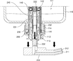
- FIG 10 and 11 are views illustrating that the liquid in the second chamber is discharged to the outside through the second discharge unit while the pump unit slides downward according to an embodiment of the present invention.
- the present invention relates to a two-way pumping machine for consuming the remaining amount of liquid, and the remaining amount of liquid is kept to the last through a two-way pumping machine that allows liquid to be discharged out of the container when the container for storing the liquid is disposed in the forward direction and the opposite direction. It relates to a two-way pump for the consumption of the remaining amount of liquid that can be consumed.
- the container 110 is disposed in the forward direction indicates that the container 110 is erected and used as shown in FIG. 1, and that the container 110 is disposed in the reverse direction, as shown in FIGS. 8 to 11. It represents the use of the container 110 upside down.
- a two-way pumping machine for consumption of the remaining liquid includes a container 110, a first chamber 130, and a body part 120 provided with a second chamber 140. ), suction pipe 131, first bearing 132, pump part 200, first piston 221, second piston 231, first discharge part 211, second discharge part 212, It includes a spring 160 and a suction unit 141.
- the container 110 is provided with an inner space 111 in which a liquid can be stored, and a coupling hole 112 communicating with the inner space 111 is provided.
- the coupling hole 112 may be a hole open to the outside, and the body portion 120 to be described later is coupled to the coupling hole 112.
- the container 110 is a container capable of storing a liquid, and the container 110 may have various shapes as long as it can store a liquid, and may be made of a material such as soft, hard, or glass.
- the liquid stored in the container 110 may be shampoo, conditioner, body wash, dish detergent, cosmetics, etc., and if it is a liquid that can be discharged to the outside through a two-way pumping machine while being stored in the container 110, the liquid Can be a variety of liquids.
- the main body 120 is provided with the first chamber 130 and the second chamber 140 in which liquid can be stored, and the main body 120 is combined with the It can be coupled to the ball 112.
- the main body 120 includes the first chamber 130 into which liquid flows when the container 110 is placed in a forward direction, and the second chamber 130 through which liquid flows when the container 110 is placed in the reverse direction.
- a chamber 140 is included, and the first chamber 130 and the second chamber 140 may be separated from each other through the partition unit 150.
- first chamber 130 and the second chamber 140 may be spaces separated from each other by the partition unit 150 within the main body 120. It is preferable that the partition unit 150 divides the first chamber 130 and the second chamber 140 so that air does not pass from the first chamber 130 to the second chamber 140.
- the main body 120 may be formed in the shape of a housing extending in the longitudinal direction, and after the middle and lower portions of the main body 120 are inserted into the inner space of the container 110, the main body 120 The upper part of the is coupled to the coupling hole (112).
- a lid portion 121 may be provided on the upper portion of the body portion 120. After the middle and lower portions of the main body 120 pass through the coupling hole 112 and are inserted into the inner space of the container 110, the lid portion 121 is placed outside the coupling hole 112. When combined, the main body 120 may be fixed to the container 110.
- a screw thread or a screw groove may be formed in the lid part 121, and a screw thread 113 or a screw groove may be formed outside the coupling hole 112 of the container 110. As the outer side of the lid part 121 and the coupling hole 112 are screwed together, the body part 120 may be fixed to the container 110.
- the coupling of the main body 120 and the container 110 is not limited to screwing, and the upper portion of the main body 120 may be coupled to the coupling hole 112 of the container 110. If there is, of course, various configurations can be used.
- a stopper part 122 may be provided on the upper part of the lid part 121, and the stopper part 122 is for supporting the pump part 200 to be described later.
- the pump unit 200 is capable of moving up and down the interior of the main body 120, and the stopper 122 is the pump unit 200 so as not to be shaken when the pump unit 200 slides up and down. 200) can be supported.
- the main body 120 may extend in a longitudinal direction, and the first chamber 130 may be disposed in a lower direction of the second chamber 140.
- the lower direction may be a direction toward the bottom of the container 110 as a lower direction.
- the suction pipe 131 is in communication with the first chamber 130 and extends to the outside of the main body 120.
- the suction pipe 131 is used when the container 110 is disposed in a forward direction, and the suction pipe 131 may be formed of a tube extending from the main body 120 to a lower direction of the container 110. .
- the container 110 is disposed in the forward direction, the liquid stored in the container 110 is moved to the first chamber 130 through the suction pipe 131.
- the first bearing 132 is provided between the first chamber 130 and the suction pipe 131 to open and close the suction pipe 131.
- the first bearing 132 is formed in a bead shape and may be disposed at the inlet of the suction pipe 131, and may open and close the suction pipe 131 according to the pressure of the first chamber 130. .
- the pump part 200 is slidably coupled to the body part 120, and includes a head part 210 protruding outside the body part 120.
- the head 210 is a point where a force is provided to allow the pump unit 200 to slide, and the user presses the head 210 to slide the pump unit 200 downward. I can.
- the spring 160 is provided under the pump unit 200 and can apply an elastic restoring force to the pump unit 200.
- the spring 160 may be disposed inside the main body 120 and may be supported through a stopper 161.
- the spring 160 compresses and applies an elastic restoring force to the pump 200, and when the user's force is removed , The pump part 200 slides upward again due to the elastic restoring force of the spring 160.
- the pump part 200 is coupled to the pump part 200 to slide together with the pump part 200, and a first movable slide in the first chamber 130
- a second piston 231 is provided that is coupled to the piston 221 and the pump unit 200 and is slidable together with the pump unit 200, and slides within the second chamber 140.
- the first piston 221 is slidable inside the first chamber 130 while the lower cross-sectional area of the first piston 221 is the same as the cross-sectional area of the first chamber 130. As the piston 221 slides up and down in the first chamber 130, the internal space of the first chamber 130 can be relaxed or compressed.
- the second piston 231 is slidable inside the second chamber 140 while the lower cross-sectional area of the second piston 231 is the same as the cross-sectional area of the second chamber 140. As the piston 231 slides up and down in the second chamber 140, the inner space of the second chamber 140 can be relaxed or compressed.
- the pump unit 200 may include a first pump unit 220 to which the first piston 221 is coupled, and a second pump unit 230 to which the second piston 231 is coupled, and the The first pump unit 220 and the second pump unit 230 may be connected through a connection unit 240.
- first pump unit 220 and the second pump unit 230 After the first pump unit 220 and the second pump unit 230 are separated and assembled, they can be connected through the connection unit 240, and the first pump unit 220 and the second pump After the unit 230 is separated and manufactured, as the first pump unit 220 and the second pump unit 230 are assembled, there is an advantage of improving the convenience of manufacturing.
- first pump unit 220 and the second pump unit 230 may be integrally manufactured.
- the head 210 of the pump part 200 has a first discharge part 211 and the second discharge part 211 communicating with the first chamber 130 and discharging the fluid in the first chamber 130 to the outside.
- a second discharge part 212 may be provided in communication with the chamber 140 to discharge the fluid of the second chamber 140 to the outside.
- the first discharge part 211 and the second discharge part 212 may be provided inside the head part 210 and serve as a passage through which fluid can be discharged to the outside.
- a first moving passage 222 connecting the first chamber 130 and the first discharge part 211, the second chamber 140, and the second discharge part A second moving channel 232 connecting the 212 may be provided.
- the first moving passage 222 is a fluid passage connected between the first chamber 130 and the first discharge part 211
- the second moving passage 232 is the second chamber 140 and the It is a fluid passage connected between the second discharge parts 212.
- the main body 120 may be provided with a suction part 141 for introducing a liquid into the second chamber 140.
- the suction unit 141 is in communication with the inner space 111 of the container 110, and the liquid stored in the inner space 111 of the container 110 is removed through the suction unit 141. It can be introduced into the 2 chamber 140.
- the suction part 141 is used when the container 110 is disposed in the reverse direction, and the suction part 141 may be disposed above the container 110.
- the liquid (liquid residual amount) in the container 110 is collected in the upper part of the container 110.
- the upper part of the container 110 refers to the upper part when the container 110 is disposed in the forward direction.
- the suction unit 141 may be an inlet for moving the remaining amount of liquid to the second chamber 140 in order to consume the remaining amount of liquid, and for this purpose, the suction unit 141 is located on the top of the container 110. It is preferred to be arranged.
- a connection passage 114 for communicating the suction part 141 and the inner space 111 may be provided on an upper surface of the inner space 111 of the container 110.
- the upper surface of the inner space 110 of the container 110 refers to the upper surface of the inner space 110 when the container 110 is disposed in the forward direction.
- connection passage 114 connects the suction part 141 and the inner space 111, and the liquid in the inner space 111 flows into the suction part 141 through the connection passage 114 do.
- the fluid in the first chamber 130 is discharged to the first discharge unit 211
- the fluid in the second chamber 140 may be discharged to the second discharge part 212.
- the liquid stored in the inner space 111 of the container 110 is the suction pipe 131-the first chamber 130-the first moving passage (222)-It may be discharged by moving in the order of the first discharge unit 211.
- the liquid stored in the inner space 111 of the container 110 is collected in the upper part of the container 110 by gravity, and is collected in the upper part of the container 110.
- the liquid may include the connection passage 114 provided on the upper surface of the container 110-the suction part 141-the second chamber 140-the second moving passage 232-the second discharge part ( 212) can be moved and discharged.
- a second bearing 142 for opening and closing the second chamber 140 may be provided between the suction part 141 and the second chamber 140.
- the second bearing 142 is provided between the second chamber 140 and the suction part 141 to open and close the second chamber 140.
- the second bearing 142 may be formed in a bead shape and may be disposed at the entrance of the second chamber 140.
- the main body 120 is provided with a second chamber outer wall 140a forming the second chamber 140, and the bead-shaped second bearing 142 is at the entrance of the second chamber outer wall 140a. It is provided with a through hole (142a) that can be installed.
- the second bearing 142 is installed in the through hole 142a to open and close the second chamber 140 according to the pressure of the second chamber 140.
- the container 110 when the container 110 is disposed in a forward direction, the liquid inside the container 110 is removed from the suction pipe 131- 1 chamber 130-the first moving passage 222-the first discharge portion 211 is moved in the order of discharge, and if the container 110 is disposed in the reverse direction, the container 110 The liquid inside is moved and discharged in the order of the connection passage 114-the suction part 141-the second chamber 140-the second moving passage 232-the second discharge part 212 will be.
- the first piston 221 coupled to the pump part 200 slides to the lower part of the first chamber 130 to compress the first chamber 130. do.
- the first bearing 132 is pushed to the outside by a compressive force generated when the space of the first chamber 130 is compressed, thereby blocking the entrance of the suction pipe 131.
- the first bearing 132 has a bead shape having a diameter larger than that of the inlet of the suction pipe 131 and is not inserted into the suction pipe 131 and can block the suction pipe 131.
- the pump part 200 slides upward by the elastic restoring force of the spring 160 provided under the pump part 200, and the pump The first piston 221 coupled to the part 200 is also slid upward.
- the pump part 200 When the user applies a force to the head part 210 again, the pump part 200 is pressed and the first piston 221 coupled to the pump part 200 moves to the lower part of the first chamber 130. The slide is moved, and accordingly, the first chamber 130 is compressed. (At this time, the first bearing 132 blocks the suction pipe 131 again.)
- the liquid introduced into the first chamber 130 is also moved to the first moving channel 222 by receiving a compressive force, and the liquid moved to the first moving channel 222 Is discharged to the outside along the first discharge part 211.
- the user removes the force pressing the head 210, the liquid inside the container 110 flows into the first chamber 130 while the above-described process is repeated.
- the container 110 Since the user cannot discharge the liquid in the order of the suction pipe 131-the first chamber 130-the first moving passage 222-the first discharge part 211, the remaining liquid is used.
- the container 110 is disposed in the reverse direction.
- the liquid in the container 110 is collected in the upper part of the container 110 by gravity.
- the user applies a force to the head 210 after disposing the container 110 in the reverse direction.
- the pump part 200 When a user applies a force to the head part 210, the pump part 200 is pressed. As the pump part 200 is pressed, the second piston 231 coupled to the pump part 200 slides to the lower part of the second chamber 140 to compress the second chamber 140. do. (The upper part refers to the upward direction when the container 110 is placed in the forward direction, and the lower part refers to the downward direction when the container 110 is disposed in the forward direction.)
- the second bearing 142 is pushed to the outside by a compressive force generated when the space of the second chamber 140 is compressed, thereby blocking the entrance of the second chamber 140.
- the second bearing 142 is in the form of a bead having a diameter larger than the diameter of the through hole 142a, which is the entrance of the second chamber 140, and is not inserted into the suction part 141, and the second chamber ( 140).
- the pump part 200 is formed by the elastic restoring force of the spring 160 provided under the pump part 200. Is slid upward, and the second piston 231 coupled to the pump unit 200 is also slid upward.
- the liquid provided in the inner space 111 of the container 110 passes through the connection channel 114 provided on the upper surface of the container 110 by the force that the space of the second chamber 140 is relaxed. It is introduced into the second chamber 140 through the suction part 141.
- the liquid introduced into the second chamber 140 is also moved to the second moving passage 232 by receiving a compressive force, and the liquid moved to the second moving passage 232 Is discharged to the outside along the second discharge part 212.
- the user removes the force pressing the head 210, the liquid inside the container 110 flows into the second chamber 140 while repeating the above-described process.
- the two-way pump for consumption of the remaining liquid discharges the liquid inside the container 110 both when the container 110 is erected in the forward direction and when the container 110 is erected in the reverse direction through the above-described operating method. It can be done.
- the user uses the container 110 in the forward direction and then arranges the container 110 in the reverse direction when the liquid is no longer discharged, and through this, the remaining amount of liquid can be used.
- An air discharge hole 133 may be formed above the first chamber 130 of the bidirectional pumping machine for consumption of the remaining liquid according to an embodiment of the present invention. As described above, the first chamber 130 and the second chamber 140 are separated into the partition unit 150 in the main body 120.
- first chamber 130 and the second chamber 140 can be divided due to the partition unit 150, the first piston 221 slides upward and downward in the first chamber 130. There is a concern that air may move from the first chamber 130 to the second chamber 140 by the pressure of.
- the air discharge hole 133 is to prevent this, and is provided on the first chamber 130 and discharges air to the outside of the first chamber 130 to reduce the pressure inside the first chamber 130. It can be lowered.
- the bidirectional pump for consumption of the remaining liquid according to the embodiment of the present invention described above has the following effects.
- the suction hose of a conventional pumping machine has a problem that it is impossible to discharge the liquid in the liquid container to the end as it is separated from the bottom of the liquid container without being in close contact with the bottom of the liquid container in order to easily discharge the liquid stored in the liquid container. Since the remaining amount of liquid remaining on the bottom of the liquid container is quite large, it is uneconomical to discard the remaining amount of liquid without using it, and there is a problem that environmental pollution is caused by the remaining amount of liquid.
- the two-way pumping machine for consumption of the remaining liquid can discharge the liquid out of the container when the container storing the liquid is disposed in the forward direction and the reverse direction. There is an advantage that can be consumed.
- the two-way pumping machine for consumption of the remaining liquid uses a pump part-second piston-second bearing when the container storing the liquid is disposed in the reverse direction. 2 Movement flow path-As the liquid is discharged to the second discharge part, there is an advantage that the remaining amount of liquid can be easily used.
- the two-way pump for consumption of the remaining amount of liquid has the advantage of economically using the liquid as the remaining amount of liquid is consumed until the end, and environmental pollution by preventing the remaining amount of liquid from being discarded. There is an effect that can prevent.
Landscapes
- Containers And Packaging Bodies Having A Special Means To Remove Contents (AREA)
- Closures For Containers (AREA)
- Reciprocating Pumps (AREA)
Abstract
본 발명은 액체 잔량 소비를 위한 양방향 펌핑기에 관한 것으로, 용기; 내부에 액체가 저장될 수 있는 제1챔버와 제2챔버가 구비된 본체부; 상기 본체부로 외부로 연장되는 흡입관; 상기 흡입관을 개폐시키는 제1베어링; 상기 본체부 외부로 돌출되는 머리부를 포함하는 펌프부; 상기 제1챔버 내부에서 슬라이드 이동되는 제1피스톤; 상기 제2챔버 내부에서 슬라이드 이동되는 제2피스톤; 상기 제1챔버의 유체를 외부로 배출시키는 제1토출부; 상기 제2챔버의 유체를 외부로 배출시키는 제2토출부; 상기 펌프부에 탄성 복원력을 가하는 스프링; 상기 제2챔버로 액체를 유입시킬 수 있는 흡입부;를 포함하는 것을 특징으로 하는 것이다.
Description
본 발명은 액체 잔량 소비를 위한 양방향 펌핑기에 관한 것으로, 더욱 상세하게는 액체를 저장하는 용기를 정방향으로 배치하였을 때와 역방향으로 배치하였을 때에 액체가 용기 밖으로 배출될 수 있도록 하는 양방향 펌핑기를 통해 액체의 잔량을 마지막까지 소비할 수 있는 액체 잔량 소비를 위한 양방향 펌핑기에 관한 것이다.
일반적으로, 샴푸, 린스, 바디워시, 주방세제, 화장품 등 어느 정도 점성을 가지고 있는 유체는 액체 용기에 담아져 사용자에게 유통된다. 액체 용기는 뚜껑이 구비되면서 뚜껑을 열고 닫아서 사용하는 액체 용기가 있으며, 나사형 펌핑기를 사용하여 나사형 펌핑기를 통해 액체 용기 내부의 액체를 외부로 배출하는 액체 용기가 있다.
나사형 펌핑기를 사용하는 액체 용기는 액체의 종류에 따라 점성의 차이가 있기 때문에 액상물을 용기에서 외부로 배출 가능하도록 각각의 다른 토출압을 가지고 있으며, 이에 따라 1회 토출량도 제품마다 차이가 있다. 또한, 액체 용기의 높이나 용량도 제품마다 차이가 있어, 펌핑기를 대부분 일회용으로 사용하고 있는 실정이다.
종래의 펌핑기를 사용하는 액체 용기는 높이에 따라 흡입호스의 길이가 다르게 형성되어 있으며, 액체 용기 내부에 저장된 액체를 최대한 용이하게 배출하기 위해 액체 용기 바닥에 완전히 밀착시키지 않고 약간의 간격을 두면서, 흡입호스 말단을 사선으로 재단하여 설치한다.
그러나 이와 같은 종래의 펌핑기를 사용하는 액체 용기는 다음과 같은 문제점이 있다. 상술한 바와 같이 흡입호스는 액체 용기 내부에 저장된 액체를 용이하게 배출하기 위해 액체 용기 바닥에 밀착되지 않으면서 용기 바닥과 이격되어 있다. 이로 인해 종래의 펌핑기를 통해서는 액체 용기 내 액체를 끝까지 토출시키는 것이 불가능한 문제점이 있다.
액체 용기에서 바닥에 남아있는 액체의 잔량이 상당히 많기 때문에, 이와 같은 액체 잔량을 사용하지 않고 버리는 것은 비경제적인 문제점이 있다. 또한, 액체 용기 내부에 남아있는 액체 잔량을 사용하지 않고 버리게 되면, 액체 잔량에 의해 환경 오염이 유발되는 문제점이 있다.
액체 용기 내부에 남아있는 액체 잔량을 사용하기 위해서, 액체 용기를 거꾸로 놓았다가 뚜껑을 열어 사용할 수는 있으나, 액체가 뚜껑 오픈부 부분에 몰려있어 필요한 양보다 훨씬 더 많은 양의 액체가 한 번에 쏟아지는 문제가 있다.
또한, 액체 용기 내부에 남아있는 액체 잔량을 사용하기 위해 액체 용기 내부에 물을 보충하여 흔들어 사용할 수도 있지만, 이와 같은 경우 액체 용기 내부에서 단시간에 세균 번식 및 세균 감염 등이 발생할 수 있어 사용자에게 악영향을 미치는 문제점이 있다.
본 발명은 상술한 문제점을 해결하기 위한 것으로, 더욱 상세하게는 액체를 저장하는 용기를 정방향으로 배치하였을 때와 역방향으로 배치하였을 때에 액체가 용기 밖으로 배출될 수 있도록 하는 양방향 펌핑기를 통해 액체의 잔량을 마지막까지 소비할 수 있는 액체 잔량 소비를 위한 양방향 펌핑기에 관한 것이다.
상술한 문제점을 해결하기 위한 본 발명의 액체 잔량 소비를 위한 양방향 펌핑기는, 액체가 저장될 수 있는 내부 공간이 구비되며, 상기 내부 공간과 연통되는 결합공이 구비된 용기; 상기 결합공에 결합되며, 내부에 액체가 저장될 수 있는 제1챔버와 제2챔버가 구비된 본체부; 상기 제1챔버와 연통되면서 상기 본체부로 외부로 연장되는 흡입관; 상기 제1챔버와 상기 흡입관 사이에 구비되면서 상기 흡입관을 개폐시키는 제1베어링; 상기 본체부에 슬라이드 이동 가능하게 결합되며, 상기 본체부 외부로 돌출되는 머리부를 포함하는 펌프부; 상기 펌프부에 결합되어 상기 펌프부와 함께 슬라이드 이동 가능하며, 상기 제1챔버 내부에서 슬라이드 이동되는 제1피스톤; 상기 펌프부에 결합되어 상기 펌프부와 함께 슬라이드 이동 가능하며, 상기 제2챔버 내부에서 슬라이드 이동되는 제2피스톤; 상기 펌프부 하부에 구비되며, 상기 펌프부에 탄성 복원력을 가하는 스프링; 상기 제2챔버로 액체를 유입시킬 수 있는 흡입부;를 포함하는 것을 특징으로 하는 것이다.
상술한 문제점을 해결하기 위한 본 발명의 액체 잔량 소비를 위한 양방향 펌핑기는 상기 펌프부의 머리부에 구비되며, 상기 제1챔버와 연통되면서 상기 제1챔버의 유체를 외부로 배출시키는 제1토출부; 상기 펌프부의 머리부에 구비되며, 상기 제2챔버와 연통되면서 상기 제2챔버의 유체를 외부로 배출시키는 제2토출부;를 더 포함하며, 상기 용기를 정방향으로 배치하였을 때는 상기 제1챔버의 유체가 상기 제1토출부를 통해 배출되며, 상기 용기를 역방향으로 배치하였을 때는 상기 제2챔버의 유체가 상기 제2토출부를 통해 배출될 수 있다.
상술한 문제점을 해결하기 위한 본 발명의 액체 잔량 소비를 위한 양방향 펌핑기는 상기 펌프부 내부에 구비되며, 상기 제1챔버와 상기 제1토출부를 연결시키는 제1이동 유로와, 상기 펌프부 내부에 구비되며, 상기 제2챔버와 상기 제2토출부를 연결시키는 제2이동 유로를 더 포함할 수 있다.
상술한 문제점을 해결하기 위한 본 발명의 액체 잔량 소비를 위한 양방향 펌핑기의 상기 용기의 내부 공간 상면에는, 상기 흡입부와 상기 내부 공간을 연통시키는 연결 유로가 구비될 수 있다.
상술한 문제점을 해결하기 위한 본 발명의 액체 잔량 소비를 위한 양방향 펌핑기의 상기 흡입부와 상기 제2챔버 사이에는, 상기 제2챔버를 개폐시키는 제2베어링이 구비되며, 상기 제2베어링은, 상기 펌프부가 하강시 상기 흡입부와 상기 제2챔버 사이의 공간을 닫히게 하며, 상기 펌프부가 상승시 상기 흡입부와 상기 제2챔버 사이의 공간을 열리게 할 수 있다.
상술한 문제점을 해결하기 위한 본 발명의 액체 잔량 소비를 위한 양방향 펌핑기의 상기 본체부에는, 상기 제1챔버와 상기 제2챔버를 구획하는 구획부가 구비될 수 있다.
상술한 문제점을 해결하기 위한 본 발명의 액체 잔량 소비를 위한 양방향 펌핑기의 상기 펌프부는, 상기 제1피스톤이 결합되는 제1펌프부와, 상기 제2피스톤이 결합되는 제2펌프부를 포함하며, 상기 제1펌프부와 상기 제2펌프부는 연결부를 통해 연결될 수 있다.
상술한 문제점을 해결하기 위한 본 발명의 액체 잔량 소비를 위한 양방향 펌핑기의 상기 제1챔버 상부에는 공기 배출 구멍이 구비될 수 있다.
본 발명은 액체 잔량 소비를 위한 양방향 펌핑기에 관한 것으로, 액체를 저장하는 용기를 정방향으로 배치하였을 때와 역방향으로 배치하였을 때에 액체가 용기 밖으로 배출될 수 있도록 하는 양방향 펌핑기를 사용함에 따라 액체의 잔량을 마지막까지 소비할 수 있는 장점이 있다.
또한, 본 발명은 액체의 잔량을 마지막까지 소비함에 따라 경제적으로 액체를 사용할 수 있는 장점이 있으며, 액체의 잔량이 버려지는 것을 방지함에 따라 환경오염을 방지할 수 있는 효과가 있다.
도 1은 본 발명의 실시 예에 따른 액체 잔량 소비를 위한 양방향 펌핑기의 측면도와 정면도이다.
도 2는 도 1의 A-A에 대한 단면도이다.
도 3은 도 2의 부분 확대도이다.
도 4는 본 발명의 실시 예에 따라 용기에서 분리된 본체부와 펌프부의 단면도이다.
도 5는 본 발명의 실시 예에 따라 용기에서 분리된 본체부와 펌프부를 나타내는 도면이다.
도 6은 본 발명의 실시 예에 따른 펌프부를 나타내는 도면이다.
도 7은 본 발명의 실시 예에 따른 제2챔버의 외벽과 제2베어링 설치를 위한 관통공을 나타내는 도면이다.
도 8 및 도 9는 본 발명의 실시 예에 따라 펌프부가 상부로 슬라이드 이동할 때 제2챔버로 액체가 유입되는 것을 나타내는 도면이다.
도 10 및 도 11은 본 발명의 실시 예에 따라 펌프부가 하부로 슬라이드 이동되면서 제2챔버의 액체가 제2토출부를 통해 외부로 배출되는 것을 나타내는 도면이다.
본 명세서는 본 발명의 권리범위를 명확히 하고, 본 발명이 속하는 기술분야에서 통상의 지식을 가진 자가 본 발명을 실시할 수 있도록, 본 발명의 원리를 설명하고, 실시 예들을 개시한다. 개시된 실시 예들은 다양한 형태로 구현될 수 있다.
본 발명의 다양한 실시 예에서 사용될 수 있는 "포함한다" 또는 "포함할 수 있다" 등의 표현은 발명(disclosure)된 해당 기능, 동작 또는 구성요소 등의 존재를 가리키며, 추가적인 하나 이상의 기능, 동작 또는 구성요소 등을 제한하지 않는다. 또한, 본 발명의 다양한 실시예에서, "포함하다" 또는 "가지다" 등의 용어는 명세서상에 기재된 특징, 숫자, 단계, 동작, 구성요소, 부품 또는 이들을 조합한 것이 존재함을 지정하려는 것이지, 하나 또는 그 이상의 다른 특징들이나 숫자, 단계, 동작, 구성요소, 부품 또는 이들을 조합한 것들의 존재 또는 부가 가능성을 미리 배제하지 않는 것으로 이해되어야 한다.
어떤 구성요소가 다른 구성요소에 "연결되어, 결합되어" 있다고 언급된 때에는, 상기 어떤 구성요소가 상기 다른 구성요소에 직접적으로 연결 또는 결합되어 있을 수도 있지만, 상기 어떤 구성요소와 상기 다른 구성요소 사이에 새로운 다른 구성요소가 존재할 수도 있다고 이해되어야 할 것이다. 반면에, 어떤 구성요소가 다른 구성요소에 "직접 연결되어" 있다거나 "직접 결합되어" 있다고 언급된 때에는, 상기 어떤 구성요소와 상기 다른 구성요소 사이에 새로운 다른 구성요소가 존재하지 않는 것으로 이해될 수 있어야 할 것이다.
본 명세서에서 사용되는 제1, 제2 등의 용어는 다양한 구성요소들을 설명하는데 사용될 수 있지만, 구성요소들은 용어들에 의해 한정되어서는 안 된다. 용어들은 하나의 구성요소를 다른 구성요소로부터 구별하는 목적으로만 사용된다.
본 발명은 액체 잔량 소비를 위한 양방향 펌핑기에 관한 것으로, 액체를 저장하는 용기를 정방향으로 배치하였을 때와 역방향으로 배치하였을 때에 액체가 용기 밖으로 배출될 수 있도록 하는 양방향 펌핑기를 통해 액체의 잔량을 마지막까지 소비할 수 있는 액체 잔량 소비를 위한 양방향 펌핑기에 관한 것이다. 이하, 첨부된 도면을 참조하여 본 발명의 바람직한 실시 예를 상세하게 설명하기로 한다.
이하의 설명에서 용기(110)가 정방향으로 배치된다는 것은 도 1과 같이 상기 용기(110)를 세워서 사용하는 것을 나타내며, 상기 용기(110)가 역방향으로 배치된다는 것은, 도 8 내지 도 11과 같이 상기 용기(110)를 뒤집어서 사용하는 것을 나타낸다.
도 1 및 도 2를 참조하면, 본 발명의 실시 예에 따른 액체 잔량 소비를 위한 양방향 펌핑기는, 용기(110), 제1챔버(130)와 제2챔버(140)가 구비된 본체부(120), 흡입관(131), 제1베어링(132), 펌프부(200), 제1피스톤(221), 제2피스톤(231), 제1토출부(211), 제2토출부(212), 스프링(160), 흡입부(141)를 포함한다.
도 2를 참조하면, 상기 용기(110)는 액체가 저장될 수 있는 내부 공간(111)이 구비되는 것으로, 상기 내부 공간(111)과 연통되는 결합공(112)이 구비되어 있는 것이다. 상기 결합공(112)은 외부로 열려 있는 구멍일 수 있으며, 상기 결합공(112)에 후술할 상기 본체부(120)가 결합된다.
상기 용기(110)는 액체를 저장할 수 있는 용기로, 상기 용기(110)는 액체를 저장할 수 있다면 다양한 형상으로 이루어질 수 있으며, 연질, 경질, 유리 등의 재질로 제작될 수 있다. 상기 용기(110)에 저장되는 액체는 샴푸, 린스, 바디워시, 주방세제, 화장품 등이 될 수 있는 것으로, 상기 용기(110)에 저장되면서 양방향 펌핑기를 통해 외부로 배출될 수 있는 액체라면 상기 액체는 다양한 액체일 수 있다.
도 3을 참조하면, 상기 본체부(120)는 내부에 액체가 저장될 수 있는 상기 제1챔버(130)와 상기 제2챔버(140)가 구비된 것으로, 상기 본체부(120)는 상기 결합공(112)에 결합될 수 있는 것이다.
상기 본체부(120)는, 상기 용기(110)를 정방향으로 배치하였을 때 액체가 유입되는 상기 제1챔버(130)와, 상기 용기(110)를 역방향으로 배치하였을 때 액체가 유입되는 상기 제2챔버(140)를 포함하는 것으로, 상기 제1챔버(130)와 상기 제2챔버(140)는 구획부(150)를 통해 서로 분리될 수 있다.
즉, 상기 제1챔버(130)와 상기 제2챔버(140)는 상기 본체부(120) 내부에서 상기 구획부(150)에 의해 서로 분리된 공간일 수 있다. 상기 구획부(150)는 상기 제1챔버(130)에서 상기 제2챔버(140)로 공기가 통하지 않도록 상기 제1챔버(130)와 상기 제2챔버(140)를 구획하는 것이 바람직하다.
상기 본체부(120)는 길이 방향으로 연장된 하우징 형태로 이루어질 수 있으며, 상기 본체부(120)의 중간부와 하부가 상기 용기(110) 내부 공간으로 삽입된 이후에, 상기 본체부(120)의 상부가 상기 결합공(112)에 결합된다.
상기 본체부(120)를 상기 결합공(112)에 결합시키기 위해, 상기 본체부(120) 상부에는 뚜껑부(121)가 구비될 수 있다. 상기 본체부(120)의 중간부와 하부가 상기 결합공(112)을 통과하여 상기 용기(110) 내부 공간으로 삽입된 이후에, 상기 뚜껑부(121)를 상기 결합공(112)의 외측에 결합시키면, 상기 본체부(120)가 상기 용기(110)에 고정될 수 있다.
상기 뚜껑부(121)에는 나사산 또는 나사홈이 형성될 수 있으며, 상기 용기(110)의 상기 결합공(112)의 외측에는 나사산(113) 또는 나사홈이 형성될 수 있다. 상기 뚜껑부(121)와 상기 결합공(112)의 외측이 나사 조립되면서 상기 본체부(120)가 상기 용기(110)에 고정될 수 있다.
다만, 상기 본체부(120)와 상기 용기(110)의 결합은 나사 결합으로 한정되는 것은 아니며, 상기 본체부(120)의 상부를 상기 용기(110)의 상기 결합공(112)에 결합시킬 수 있다면 다양한 구성이 사용될 수 있음은 물론이다.
상기 뚜껑부(121)의 상부에는 마개부(122)가 구비될 수 있으며, 상기 마개부(122)는 후술할 상기 펌프부(200)를 지지하기 위한 것이다. 상기 펌프부(200)는 상기 본체부(120) 내부를 상, 하 슬라이드 이동할 수 있는 것인데, 상기 마개부(122)는 상기 펌프부(200)가 상, 하 슬라이드 이동할 때 흔들리지 않도록 상기 펌프부(200)를 지지할 수 있는 것이다.
도 4 및 도 5를 참조하면, 상기 본체부(120)는 길이 방향으로 연장될 수 있는데, 상기 제1챔버(130)는 상기 제2챔버(140)의 하부 방향에 배치될 수 있다. 여기서, 하부 방향이라 함은 상기 용기(110)의 바닥을 향하는 방향이 하부 방향일 수 있다.
상기 흡입관(131)은 상기 제1챔버(130)와 연통되면서 상기 본체부(120)의 외부로 연장되는 것이다. 상기 흡입관(131)은 상기 용기(110)가 정방향으로 배치되었을 때 사용되는 것으로, 상기 흡입관(131)은 상기 본체부(120)에서 상기 용기(110)의 하부 방향으로 연장되는 관으로 이루어질 수 있다. 상기 용기(110)가 정방향으로 배치되었을 때, 상기 흡입관(131)을 통해 상기 제1챔버(130)로 상기 용기(110)에 저장되어 있는 액체가 이동된다.
도 4를 참조하면, 상기 제1베어링(132)은 상기 제1챔버(130)와 상기 흡입관(131) 사이에 구비되면서 상기 흡입관(131)을 개폐시킬 수 있는 것이다. 상기 제1베어링(132)은 구슬 형태로 이루어지면서 상기 흡입관(131)의 입구에 배치될 수 있는 것으로, 상기 제1챔버(130)의 압력에 따라 상기 흡입관(131)을 열리고 닫히게 할 수 있는 것이다.
도 2 내지 도 4를 참조하면, 상기 펌프부(200)는 상기 본체부(120)에 슬라이드 이동 가능하게 결합되는 것으로, 상기 본체부(120) 외부로 돌출되는 머리부(210)를 포함하는 것이다. 상기 머리부(210)는 상기 펌프부(200)가 슬라이드 이동 가능할 수 있도록 하는 힘이 제공되는 지점으로, 사용자는 상기 머리부(210)를 누름으로써 상기 펌프부(200)를 하부로 슬라이드 이동시킬 수 있다.
상기 스프링(160)은 상기 펌프부(200)의 하부에 구비되는 것으로, 상기 펌프부(200)에 탄성 복원력을 가할 수 있는 것이다. 상기 스프링(160)은 상기 본체부(120) 내부에 배치될 수 있는 것으로, 스토퍼(161)를 통해 지지될 수 있다.
사용자가 상기 머리부(210)를 눌러 상기 펌프부(200)를 하부로 슬라이드 이동시키면, 상기 스프링(160)은 압축되면서 상기 펌프부(200)에 탄성 복원력을 가하게 되고, 사용자의 힘이 제거되면, 상기 펌프부(200)는 상기 스프링(160)의 탄성 복원력으로 인해 다시 상부로 슬라이드 이동하게 된다.
도 6을 참조하면, 상기 펌프부(200)에는, 상기 펌프부(200)에 결합되어 상기 펌프부(200)와 함께 슬라이드 이동 가능하며, 상기 제1챔버(130) 내부에서 슬라이드 이동되는 제1피스톤(221)과 상기 펌프부(200)에 결합되어 상기 펌프부(200)와 함께 슬라이드 이동 가능하며, 상기 제2챔버(140) 내부에서 슬라이드 이동되는 제2피스톤(231)이 구비되어 있다.
상기 제1피스톤(221)은 상기 제1피스톤(221)의 하부 단면적이 상기 제1챔버(130)의 단면적과 동일하게 이루어지면서 상기 제1챔버(130) 내부에서 슬라이드 이동 가능한 것으로, 상기 제1피스톤(221)이 상기 제1챔버(130)에서 상, 하 슬라이드 이동하면서 상기 제1챔버(130) 내부 공간을 이완시키거나 압축할 수 있게 된다.
상기 제2피스톤(231)은 상기 제2피스톤(231)의 하부 단면적이 상기 제2챔버(140)의 단면적과 동일하게 이루어지면서 상기 제2챔버(140) 내부에서 슬라이드 이동 가능한 것으로, 상기 제2피스톤(231)이 상기 제2챔버(140)에서 상, 하 슬라이드 이동하면서 상기 제2챔버(140) 내부 공간을 이완시키거나 압축할 수 있게 된다.
상기 펌프부(200)는 상기 제1피스톤(221)이 결합되는 제1펌프부(220)와, 상기 제2피스톤(231)이 결합되는 제2펌프부(230)를 포함할 수 있으며, 상기 제1펌프부(220)와 상기 제2펌프부(230)는 연결부(240)를 통해 연결될 수 있다.
상기 제1펌프부(220)와 상기 제2펌프부(230)는 분리되어 조립된 이후에, 상기 연결부(240)를 통해 연결될 수 있는 것으로, 상기 제1펌프부(220)와 상기 제2펌프부(230)를 분리하여 제작한 이후에 상기 제1펌프부(220)와 상기 제2펌프부(230)를 조립함에 따라 제작의 편의성을 향상시킬 수 있는 장점이 있다.
다만, 이에 한정되는 것은 아니며, 상기 제1펌프부(220)와 상기 제2펌프부(230)는 일체로 제작될 수도 있다.
상기 펌프부(200)의 상기 머리부(210)에는, 상기 제1챔버(130)와 연통되면서 상기 제1챔버(130)의 유체를 외부로 배출시키는 제1토출부(211)와 상기 제2챔버(140)와 연통되면서 상기 제2챔버(140)의 유체를 외부로 배출시키는 제2토출부(212)가 구비될 수 있다.
상기 제1토출부(211)와 상기 제2토출부(212)는 상기 머리부(210)의 내부에 구비될 수 있는 것으로, 유체를 외부로 배출시킬 수 있는 통로가 되는 것이다. 상기 펌프부(200) 내부에는, 상기 제1챔버(130)와 상기 제1토출부(211)를 연결시키는 제1이동 유로(222)와 상기 제2챔버(140)와 상기 제2토출부(212)를 연결시키는 제2이동 유로(232)가 구비될 수도 있다.
상기 제1이동 유로(222)는 상기 제1챔버(130)와 상기 제1토출부(211) 사이에 연결된 유체 통로이며, 상기 제2이동 유로(232)는 상기 제2챔버(140)와 상기 제2토출부(212) 사이에 연결된 유체 통로이다.
상기 본체부(120)에는 상기 제2챔버(140)로 액체를 유입시키는 흡입부(141)가 구비될 수 있다. 상기 흡입부(141)는 상기 용기(110)의 내부 공간(111)과 연통된 것으로, 상기 용기(110)의 내부 공간(111)에 저장되어 있는 액체는 상기 흡입부(141)를 통해 상기 제2챔버(140)로 유입될 수 있다.
상기 흡입부(141)는 상기 용기(110)가 역방향으로 배치되었을 때 사용되는 것으로, 상기 흡입부(141)는 상기 용기(110)의 상부에 배치될 수 있는 것이다. 상기 용기(110)를 역방향으로 배치하면, 상기 용기(110)의 액체(액체 잔량)는 상기 용기(110)의 상부로 모이게 된다. (여기서 상기 용기(110)의 상부라 함은, 상기 용기(110)를 정방향으로 배치하였을 때의 윗부분을 말한다.)
상기 흡입부(141)는 액체 잔량을 소비하기 위해 상기 제2챔버(140)로 액체 잔량을 이동시키는 입구가 될 수 있는 것으로, 이를 위해 상기 흡입부(141)는 상기 용기(110)의 상부에 배치되는 것이 바람직하다.
도 3을 참조하면, 상기 용기(110)의 내부 공간(111) 상면에는 상기 흡입부(141)와 상기 내부 공간(111)을 연통시키는 연결 유로(114)가 구비될 수도 있다. (여기서 상기 용기(110)의 내부 공간(110) 상면이라 함은, 상기 용기(110)를 정방향으로 배치하였을 때의 상기 내부 공간(110)의 윗면을 말한다.)
상기 연결 유로(114)는 상기 흡입부(141)와 상기 내부 공간(111)을 연결시키는 것으로, 상기 내부 공간(111)의 액체는 상기 연결 유로(114)를 통해 상기 흡입부(141)로 유입된다.
본 발명의 실시 예에 따른 액체 잔량 소비를 위한 양방향 펌핑기는, 상기 용기(110)를 정방향으로 배치하였을 경우에는 상기 제1챔버(130)의 유체가 상기 제1토출부(211)로 배출되며, 상기 용기(110)를 역방향으로 배치하였을 경우에는 상기 제2챔버(140)의 유체가 상기 제2토출부(212)로 배출될 수 있는 것이다.
구체적으로, 상기 용기(110)가 정방향으로 배치되었을 때, 상기 용기(110)의 내부 공간(111)에 저장된 액체는, 상기 흡입관(131)-상기 제1챔버(130)-상기 제1이동 유로(222)-상기 제1토출부(211)의 순서로 이동되어 배출될 수 있다.
상기 용기(110)가 역방향으로 배치되었을 때는, 상기 용기(110)의 내부 공간(111)에 저장된 액체는 중력에 의해 상기 용기(110)의 상부로 모이게 되며, 상기 용기(110)의 상부로 모인 액체는, 상기 용기(110)의 상면에 구비된 상기 연결 유로(114)-상기 흡입부(141)-상기 제2챔버(140)-상기 제2이동 유로(232)-상기 제2토출부(212)의 순서로 이동되어 배출될 수 있다.
상기 흡입부(141)와 상기 제2챔버(140) 사이에는, 상기 제2챔버(140)를 개폐시키는 제2베어링(142)이 구비될 수 있다. 상기 제2베어링(142)은 상기 제2챔버(140)와 상기 흡입부(141) 사이에 구비되면서 상기 제2챔버(140)를 개폐시킬 수 있는 것이다.
도 4 및 도 7을 참조하면, 상기 제2베어링(142)은 구슬 형태로 이루어지면서 상기 제2챔버(140)의 입구에 배치될 수 있는 것이다. 상기 본체부(120)에는 상기 제2챔버(140)를 형성하는 제2챔버 외벽(140a)이 구비되어 있으며, 상기 제2챔버 외벽(140a) 입구에는 구슬 형태의 상기 제2베어링(142)이 설치될 수 있는 관통공(142a)이 구비되어 있다. 상기 제2베어링(142)은 상기 관통공(142a)에 설치되면서, 상기 제2챔버(140)의 압력에 따라 상기 제2챔버(140)를 열리고 닫히게 할 수 있는 것이다.
상술한 것과 같이 본 발명의 실시 예에 따른 액체 잔량 소비를 위한 양방향 펌핑기는, 상기 용기(110)가 정방향으로 배치되어 있을 경우에는 상기 용기(110) 내부의 액체를 상기 흡입관(131)-상기 제1챔버(130)-상기 제1이동 유로(222)-상기 제1토출부(211)의 순서로 이동시켜 배출하는 것이며, 상기 용기(110)가 역방향으로 배치되어 있을 경우에는 상기 용기(110) 내부의 액체를 상기 연결 유로(114)-상기 흡입부(141)-상기 제2챔버(140)-상기 제2이동 유로(232)-상기 제2토출부(212)의 순서로 이동시켜 배출하는 것이다.
이하에서는 상술한 본 발명의 실시 예에 따른 액체 잔량 소비를 위한 양방향 펌핑기의 작동방법에 대해 상세하게 설명하기로 한다.
상기 용기(110)가 정방향으로 배치되었을 때, 상기 제1토출부(211)를 통해 상기 용기(110)의 액체가 배출되는 과정을 살펴보면 다음과 같다. 사용자가 상기 머리부(210)에 힘을 가하면, 상기 펌프부(200)가 눌려지게 된다.
상기 펌프부(200)가 눌림에 따라 상기 펌프부(200)에 결합되어 있는 상기 제1피스톤(221)이 상기 제1챔버(130) 하부로 슬라이드 이동되면서 상기 제1챔버(130)를 압축하게 된다. 이때, 상기 제1베어링(132)은 상기 제1챔버(130) 공간이 압축되면서 발생한 압축력에 의해 외부로 밀리면서 상기 흡입관(131)의 입구를 막게 된다. (상기 제1베어링(132)은 상기 흡입관(131)의 입구보다 직경이 크게 형성된 구슬 형태로 상기 흡입관(131)에 삽입되지 않고 상기 흡입관(131)을 막을 수 있게 된다.)
사용자가 상기 머리부(210)를 누르는 힘을 제거하면, 상기 펌프부(200) 하부에 구비된 상기 스프링(160)의 탄성 복원력에 의해 상기 펌프부(200)는 상부로 슬라이드 이동되고, 상기 펌프부(200)에 결합되어 있는 상기 제1피스톤(221)도 함께 상부로 슬라이드 이동된다.
상기 제1피스톤(221)이 상부로 슬라이드 이동됨에 따라 상기 제1챔버(130)의 공간이 이완되면서 상기 제1베어링(132)이 들리게 되고, 상기 흡입관(131)을 통해 상기 용기(110)의 내부 공간(111)에 구비된 액체가 상기 제1챔버(130)로 유입된다.
사용자가 상기 머리부(210)에 다시 힘을 가하면, 상기 펌프부(200)가 눌려지면서 상기 펌프부(200)에 결합되어 있는 상기 제1피스톤(221)이 상기 제1챔버(130) 하부로 슬라이드 이동되고, 이에 따라 상기 제1챔버(130)가 압축된다. (이때, 상기 제1베어링(132)은 상기 흡입관(131)을 다시 막게 된다.)
상기 제1챔버(130)가 압축됨에 따라 상기 제1챔버(130)에 유입된 액체도 압축력을 받아 상기 제1이동 유로(222)로 이동되고, 상기 제1이동 유로(222)로 이동된 액체는 상기 제1토출부(211)를 따라 외부로 배출된다. 사용자가 상기 머리부(210)를 누르는 힘을 제거하면, 상술한 과정이 반복되면서 상기 제1챔버(130)로 상기 용기(110) 내부의 액체가 유입된다.
상기 용기(110)가 역방향으로 배치되었을 때, 상기 제2토출부(212)를 통해 상기 용기(110)의 액체가 배출되는 과정을 살펴보면 다음과 같다. 상기 용기(110)를 역방향으로 배치하는 경우는, 상기 용기(110)를 정방향으로 사용하다가 상기 용기(110) 내부의 액체가 배출되지 않을 만큼의 액체 잔량이 남았을 경우이다.
사용자는 상기 흡입관(131)-상기 제1챔버(130)-상기 제1이동 유로(222)-상기 제1토출부(211)의 순서로 액체를 배출할 수 없기 때문에, 남아있는 액체를 사용하기 위해, 상기 용기(110)를 역방향으로 배치한다. 상기 용기(110)를 역방향으로 배치하면, 상기 용기(110)의 액체는 중력에 의해 상기 용기(110)의 상부로 모이게 된다. 사용자는 액체 잔량을 사용하기 위해, 상기 용기(110)를 역방향으로 배치한 이후에, 상기 머리부(210)에 힘을 가하게 된다.
사용자가 상기 머리부(210)에 힘을 가하면, 상기 펌프부(200)가 눌려지게 된다. 상기 펌프부(200)가 눌림에 따라 상기 펌프부(200)에 결합되어 있는 상기 제2피스톤(231)이 상기 제2챔버(140) 하부로 슬라이드 이동되면서 상기 제2챔버(140)를 압축하게 된다. (상부는 상기 용기(110)가 정방향으로 배치되었을 때 윗 방향을 말하며, 하부는 상기 용기(110)가 정방향으로 배치되었을 때 아랫 방향을 말한다.)
이때, 상기 제2베어링(142)은 상기 제2챔버(140) 공간이 압축되면서 발생한 압축력에 의해 외부로 밀리면서 상기 제2챔버(140)의 입구를 막게 된다. (상기 제2베어링(142)은 상기 제2챔버(140)의 입구인 관통공(142a)의 직경 보다 직경이 크게 형성된 구슬 형태로 상기 흡입부(141)로 삽입되지 않으면서 상기 제2챔버(140)를 막을 수 있게 된다.)
도 8 및 도 9를 참조하면, 사용자가 상기 머리부(210)를 누르는 힘을 제거하면, 상기 펌프부(200) 하부에 구비된 상기 스프링(160)의 탄성 복원력에 의해 상기 펌프부(200)는 상부로 슬라이드 이동되고, 상기 펌프부(200)에 결합되어 있는 상기 제2피스톤(231)도 함께 상부로 슬라이드 이동된다.
상기 제2피스톤(231)이 상부로 슬라이드 이동됨에 따라 상기 제2챔버(140)의 공간이 이완되면서 상기 제2베어링(142)이 들리게 되고 이에 따라 상기 제2챔버(140)의 입구가 열리게 된다.
상기 용기(110)의 내부 공간(111)에 구비된 액체는, 상기 제2챔버(140)의 공간이 이완되는 힘에 의해 상기 용기(110)의 상면에 구비된 상기 연결 유로(114)를 거쳐 상기 흡입부(141)를 통해 상기 제2챔버(140)로 유입된다.
도 10 및 도 11을 참조하면, 사용자가 상기 머리부(210)에 다시 힘을 가하면, 상기 펌프부(200)가 눌려지면서 상기 펌프부(200)에 결합되어 있는 상기 제2피스톤(231)이 상기 제2챔버(140) 하부로 슬라이드 이동되고, 이에 따라 상기 제2챔버(140)가 압축된다. (이때, 상기 제2베어링(142)은 상기 제2챔버(140)의 입구를 다시 막게 된다.)
상기 제2챔버(140)가 압축됨에 따라 상기 제2챔버(140)에 유입된 액체도 압축력을 받아 상기 제2이동 유로(232)로 이동되고, 상기 제2이동 유로(232)로 이동된 액체는 상기 제2토출부(212)를 따라 외부로 배출된다. 사용자가 상기 머리부(210)를 누르는 힘을 제거하면, 상술한 과정이 반복되면서 상기 제2챔버(140)로 상기 용기(110) 내부의 액체가 유입된다.
본 발명의 실시 예에 따른 액체 잔량 소비를 위한 양방향 펌핑기는 상술한 작동방법을 통해, 상기 용기(110)가 정방향으로 세워졌을 때와 역방향으로 세워졌을 때 모두 상기 용기(110) 내부의 액체를 배출할 수 있는 것이다.
사용자는 상기 용기(110)를 정방향으로 사용하다가 더 이상 액체가 배출되지 않을 때 상기 용기(110)를 역방향으로 배치하게 되며, 이를 통해 액체 잔량을 모두 사용할 수 있게 된다.
본 발명의 실시 예에 따른 액체 잔량 소비를 위한 양방향 펌핑기의 상기 제1챔버(130) 상부에는 공기 배출 구멍(133)이 형성될 수도 있다. 상술한 바와 같이 상기 본체부(120) 내부에서 상기 제1챔버(130)와 상기 제2챔버(140)는 상기 구획부(150)로 분리되어 있다.
상기 구획부(150)로 인해 상기 제1챔버(130)와 상기 제2챔버(140)를 구획시킬 수 있지만, 상기 제1챔버(130)에서 상, 하 슬라이드 이동되는 상기 제1피스톤(221)의 압력에 의해 상기 제1챔버(130)에서 상기 제2챔버(140)로 공기가 이동될 우려가 있다.
상기 제1챔버(130)에서 상기 제2챔버(140)로 공기가 이동하게 되면, 상기 제2챔버(140)에 저장된 액체를 상기 제2토출부(212)로 원활하게 배출할 수 없기 때문에, 상기 제1챔버(130)에서 상기 제2챔버(140)로 공기가 이동하는 것을 방지하여야 한다.
상기 공기 배출 구멍(133)은 이를 방지하기 위한 것으로, 상기 제1챔버(130) 상부에 구비되면서 상기 제1챔버(130)의 외부로 공기를 배출하여 상기 제1챔버(130) 내부의 압력을 낮출 수 있는 것이다.
상기 공기 배출 구멍(133)을 통해 상기 제1챔버(130)의 압력을 낮추면서 외부로 공기를 배출시킴에 따라 상기 제1챔버(130)에서 상기 제2챔버(140)로 공기가 이동되는 것을 방지할 수 있게 된다.
상술한 본 발명의 실시 예에 따른 액체 잔량 소비를 위한 양방향 펌핑기는 다음과 같은 효과가 있다.
종래의 펌핑기의 흡입호스는, 액체 용기 내부에 저장된 액체를 용이하게 배출하기 위해 액체 용기 바닥에 밀착시키지 않고 용기 바닥과 이격됨에 따라 액체 용기 내 액체를 끝까지 토출시키는 것이 불가능한 문제점이 있다. 액체 용기에서 바닥에 남아있는 액체의 잔량은 상당히 많기 때문에, 이와 같이 액체 잔량을 사용하지 않고 버리는 것은 비경제적이며, 액체 잔량에 의해 환경오염이 유발되는 문제점이 있다.
액체 용기 내부에 남아있는 액체 잔량을 사용하기 위해서, 액체 용기를 거꾸로 놓았다가 뚜껑을 열어 사용할 수는 있으나, 액체가 뚜껑 오픈부 부분에 몰려있어 필요한 양보다 훨씬 더 많은 양의 액체가 한 번에 쏟아지는 문제가 있다.
그러나 본 발명의 실시 예에 따른 액체 잔량 소비를 위한 양방향 펌핑기는 액체를 저장하는 용기를 정방향으로 배치하였을 때와 역방향으로 배치하였을 때에 모두 액체를 용기 밖으로 배출시킬 수 있음에 따라 액체의 잔량을 마지막까지 소비할 수 있는 장점이 있다.
특히, 본 발명의 실시 예에 따른 액체 잔량 소비를 위한 양방향 펌핑기는, 액체를 저장하는 용기를 역방향으로 배치하였을 경우에 펌프부-제2피스톤-제2베어링를 이용하여 흡입부-제2챔버-제2이동 유로-제2토출부로 액체를 배출시킴에 따라 액체 잔량을 용이하게 사용할 수 있는 장점이 있다.
이와 함께, 본 발명의 실시 예에 따른 액체 잔량 소비를 위한 양방향 펌핑기는 액체의 잔량을 마지막까지 소비함에 따라 경제적으로 액체를 사용할 수 있는 장점이 있으며, 액체의 잔량이 버려지는 것을 방지함에 따라 환경오염을 방지할 수 있는 효과가 있다.
이상, 본 발명을 바람직한 실시 예를 들어 상세하게 설명하였으나, 본 발명은 상기 실시 예에 한정되지 않으며, 본 발명의 범주를 벗어나지 않는 범위 내에서 여러 가지 많은 변형이 제공될 수 있다. 따라서, 본 발명의 진정한 기술적 보호 범위를 첨부된 특허청구범위의 기술적 사상에 의하여 정해져야 할 것이다.
Claims (8)
- 액체를 외부로 배출할 수 있는 펌핑기에 있어서,액체가 저장될 수 있는 내부 공간이 구비되며, 상기 내부 공간과 연통되는 결합공이 구비된 용기; 상기 결합공에 결합되며, 내부에 액체가 저장될 수 있는 제1챔버와 제2챔버가 구비된 본체부; 상기 제1챔버와 연통되면서 상기 본체부로 외부로 연장되는 흡입관; 상기 제1챔버와 상기 흡입관 사이에 구비되면서 상기 흡입관을 개폐시키는 제1베어링;상기 본체부에 슬라이드 이동 가능하게 결합되며, 상기 본체부 외부로 돌출되는 머리부를 포함하는 펌프부;상기 펌프부에 결합되어 상기 펌프부와 함께 슬라이드 이동 가능하며, 상기 제1챔버 내부에서 슬라이드 이동되는 제1피스톤; 상기 펌프부에 결합되어 상기 펌프부와 함께 슬라이드 이동 가능하며, 상기 제2챔버 내부에서 슬라이드 이동되는 제2피스톤;상기 펌프부 하부에 구비되며, 상기 펌프부에 탄성 복원력을 가하는 스프링;상기 제2챔버로 액체를 유입시킬 수 있는 흡입부;를 포함하는 것을 특징으로 하는 액체 잔량 소비를 위한 양방향 펌핑기.
- 제1항에 있어서,상기 펌프부의 머리부에 구비되며, 상기 제1챔버와 연통되면서 상기 제1챔버의 유체를 외부로 배출시키는 제1토출부; 상기 펌프부의 머리부에 구비되며, 상기 제2챔버와 연통되면서 상기 제2챔버의 유체를 외부로 배출시키는 제2토출부;를 더 포함하며,상기 용기를 정방향으로 배치하였을 때는 상기 제1챔버의 유체가 상기 제1토출부를 통해 배출되며,상기 용기를 역방향으로 배치하였을 때는 상기 제2챔버의 유체가 상기 제2토출부를 통해 배출되는 것을 특징으로 하는 액체 잔량 소비를 위한 양방향 펌핑기.
- 제1항에 있어서,상기 펌프부 내부에 구비되며, 상기 제1챔버와 상기 제1토출부를 연결시키는 제1이동 유로와,상기 펌프부 내부에 구비되며, 상기 제2챔버와 상기 제2토출부를 연결시키는 제2이동 유로를 더 포함하는 것을 특징으로 하는 액체 잔량 소비를 위한 양방향 펌핑기.
- 제1항에 있어서,상기 용기의 내부 공간 상면에는, 상기 흡입부와 상기 내부 공간을 연통시키는 연결 유로가 구비되는 것을 특징으로 하는 액체 잔량 소비를 위한 양방향 펌핑기.
- 제1항에 있어서,상기 흡입부와 상기 제2챔버 사이에는, 상기 제2챔버를 개폐시키는 제2베어링이 구비되며,상기 제2베어링은, 상기 펌프부가 하강시 상기 흡입부와 상기 제2챔버 사이의 공간을 닫히게 하며, 상기 펌프부가 상승시 상기 흡입부와 상기 제2챔버 사이의 공간을 열리게 하는 것을 특징으로 하는 액체 잔량 소비를 위한 양방향 펌핑기.
- 제1항에 있어서,상기 본체부에는, 상기 제1챔버와 상기 제2챔버를 구획하는 구획부가 구비되는 것을 특징으로 하는 액체 잔량 소비를 위한 양방향 펌핑기.
- 제1항에 있어서,상기 펌프부는,상기 제1피스톤이 결합되는 제1펌프부와, 상기 제2피스톤이 결합되는 제2펌프부를 포함하며,상기 제1펌프부와 상기 제2펌프부는 연결부를 통해 연결되는 것을 특징으로 하는 액체 잔량 소비를 위한 양방향 펌핑기.
- 제1항에 있어서,상기 제1챔버 상부에는 공기 배출 구멍이 구비되는 것을 특징으로 하는 액체 잔량 소비를 위한 양방향 펌핑기.
Priority Applications (4)
| Application Number | Priority Date | Filing Date | Title |
|---|---|---|---|
| US17/427,666 US11673153B2 (en) | 2019-07-19 | 2020-02-12 | Two-way pumping device for consumption of residual amount of liquid |
| JP2021551869A JP7244668B2 (ja) | 2019-07-19 | 2020-02-12 | 液体残量消費のための双方向ポンピング器 |
| CN202080017964.0A CN113543890B (zh) | 2019-07-19 | 2020-02-12 | 用于消耗液体剩余量的双向抽水机 |
| EP20843324.3A EP3907009A4 (en) | 2019-07-19 | 2020-02-12 | TWO-WAY PUMP DEVICE FOR CONSUMPTION OF A REMAINING AMOUNT OF LIQUID |
Applications Claiming Priority (4)
| Application Number | Priority Date | Filing Date | Title |
|---|---|---|---|
| KR20190087756 | 2019-07-19 | ||
| KR10-2019-0087756 | 2019-07-19 | ||
| KR1020200013318A KR102197038B1 (ko) | 2019-07-19 | 2020-02-04 | 액체 잔량 소비를 위한 양방향 펌핑기 |
| KR10-2020-0013318 | 2020-02-04 |
Publications (1)
| Publication Number | Publication Date |
|---|---|
| WO2021015380A1 true WO2021015380A1 (ko) | 2021-01-28 |
Family
ID=74088214
Family Applications (1)
| Application Number | Title | Priority Date | Filing Date |
|---|---|---|---|
| PCT/KR2020/001971 Ceased WO2021015380A1 (ko) | 2019-07-19 | 2020-02-12 | 액체 잔량 소비를 위한 양방향 펌핑기 |
Country Status (6)
| Country | Link |
|---|---|
| US (1) | US11673153B2 (ko) |
| EP (1) | EP3907009A4 (ko) |
| JP (1) | JP7244668B2 (ko) |
| KR (1) | KR102197038B1 (ko) |
| CN (1) | CN113543890B (ko) |
| WO (1) | WO2021015380A1 (ko) |
Families Citing this family (1)
| Publication number | Priority date | Publication date | Assignee | Title |
|---|---|---|---|---|
| CN114873071B (zh) * | 2022-06-20 | 2026-05-26 | 广州丽高塑料制品有限公司 | 一种具有回吸效果的泡沫泵 |
Citations (5)
| Publication number | Priority date | Publication date | Assignee | Title |
|---|---|---|---|---|
| US4305530A (en) * | 1978-01-23 | 1981-12-15 | Yoshino Kogyosho Co., Ltd. | Liquid atomizer |
| JP2002347866A (ja) * | 2001-05-23 | 2002-12-04 | Mitani Valve Co Ltd | 噴出器およびそのポンプ装置 |
| KR100370812B1 (ko) * | 1994-11-17 | 2003-02-05 | 가부시키가이샤 요시노 고교쇼 | 거품 분출 펌프 부착 용기 |
| KR20080012906A (ko) * | 2005-04-29 | 2008-02-12 | 렉삼 에어스프레이 엔.브이. | 분배 장치 |
| KR20080057451A (ko) * | 2006-12-20 | 2008-06-25 | 재단법인 포항산업과학연구원 | 누름식 펌프장치 |
Family Cites Families (18)
| Publication number | Priority date | Publication date | Assignee | Title |
|---|---|---|---|---|
| BE752932A (fr) * | 1969-07-07 | 1970-12-16 | Pulverisation Par Abreviation | Vaporisateur a tube plongeur |
| FR2260391B2 (ko) * | 1974-02-08 | 1976-11-26 | Step | |
| NL179791C (nl) | 1977-05-12 | 1986-11-17 | Yoshino Kogyosho Co Ltd | Zowel rechtop als in omgekeerde stand te gebruiken verstuiver. |
| JPS61897Y2 (ko) * | 1977-08-20 | 1986-01-13 | ||
| JPS5437516A (en) | 1977-08-30 | 1979-03-20 | Pioneer Electronic Corp | Fm receiver |
| DE3513575A1 (de) | 1985-04-16 | 1986-10-16 | Ing. Erich Pfeiffer GmbH & Co KG, 7760 Radolfzell | Handbetaetigte ausgabeeinrichtung fuer medien |
| US5217148A (en) * | 1991-02-11 | 1993-06-08 | Spruhventile Gmbh | Pharmaceutical pump dispenser |
| JPH08332423A (ja) * | 1995-04-04 | 1996-12-17 | Canyon Corp | 手動式ディスペンサ−の正立・倒立兼用バルブおよび手動式ディスペンサ− |
| NL1005189C2 (nl) | 1997-02-05 | 1998-08-06 | Airspray Int Bv | Afgeefsamenstel voor het afgeven van twee vloeibare componenten. |
| US6036113A (en) | 1998-12-04 | 2000-03-14 | D'angelo; Vincent J. | Dual head spray applicator |
| ID29685A (id) | 2000-03-15 | 2001-09-20 | Saint Gobain Calmar Sa | Dispenser pompa fluida yang mempunyai ciri penarikan produk |
| CA2504989C (en) * | 2005-04-22 | 2013-03-12 | Gotohti.Com Inc. | Stepped pump foam dispenser |
| JP4877913B2 (ja) | 2005-12-07 | 2012-02-15 | 久光製薬株式会社 | 噴射装置、および噴射器 |
| JP2009143617A (ja) | 2007-12-17 | 2009-07-02 | Mitani Valve Co Ltd | 正倒立ポンプ機構およびポンプ式製品 |
| CN201579156U (zh) * | 2009-11-04 | 2010-09-15 | 上海德昕日化有限公司 | 环保喷头 |
| CN201579158U (zh) | 2009-12-21 | 2010-09-15 | 陈秋火 | 背吸式防滴漏喷头 |
| JP3173465U (ja) | 2011-11-04 | 2012-02-09 | ユニプラス株式会社 | 直立および倒立状態でも使用可能な噴出器装置 |
| CN107654349A (zh) * | 2017-10-25 | 2018-02-02 | 江苏昊泰气体设备科技有限公司 | 一种内置排气通道的往复式活塞泵 |
-
2020
- 2020-02-04 KR KR1020200013318A patent/KR102197038B1/ko active Active
- 2020-02-12 CN CN202080017964.0A patent/CN113543890B/zh active Active
- 2020-02-12 WO PCT/KR2020/001971 patent/WO2021015380A1/ko not_active Ceased
- 2020-02-12 JP JP2021551869A patent/JP7244668B2/ja active Active
- 2020-02-12 EP EP20843324.3A patent/EP3907009A4/en active Pending
- 2020-02-12 US US17/427,666 patent/US11673153B2/en active Active
Patent Citations (5)
| Publication number | Priority date | Publication date | Assignee | Title |
|---|---|---|---|---|
| US4305530A (en) * | 1978-01-23 | 1981-12-15 | Yoshino Kogyosho Co., Ltd. | Liquid atomizer |
| KR100370812B1 (ko) * | 1994-11-17 | 2003-02-05 | 가부시키가이샤 요시노 고교쇼 | 거품 분출 펌프 부착 용기 |
| JP2002347866A (ja) * | 2001-05-23 | 2002-12-04 | Mitani Valve Co Ltd | 噴出器およびそのポンプ装置 |
| KR20080012906A (ko) * | 2005-04-29 | 2008-02-12 | 렉삼 에어스프레이 엔.브이. | 분배 장치 |
| KR20080057451A (ko) * | 2006-12-20 | 2008-06-25 | 재단법인 포항산업과학연구원 | 누름식 펌프장치 |
Non-Patent Citations (1)
| Title |
|---|
| See also references of EP3907009A4 * |
Also Published As
| Publication number | Publication date |
|---|---|
| CN113543890A (zh) | 2021-10-22 |
| US20220134368A1 (en) | 2022-05-05 |
| US11673153B2 (en) | 2023-06-13 |
| KR102197038B1 (ko) | 2020-12-30 |
| CN113543890B (zh) | 2023-08-04 |
| JP2022522800A (ja) | 2022-04-20 |
| JP7244668B2 (ja) | 2023-03-22 |
| EP3907009A1 (en) | 2021-11-10 |
| EP3907009A4 (en) | 2022-09-28 |
Similar Documents
| Publication | Publication Date | Title |
|---|---|---|
| WO2009091173A2 (ko) | 수동식 분사펌프 | |
| WO2015023104A1 (ko) | 탄성버튼을 이용한 압출식 화장품 용기 | |
| WO2015008906A1 (ko) | 크림타입 화장품 용기 | |
| WO2012070843A2 (ko) | 이종 내용물 혼합용기 | |
| WO2013137564A1 (en) | Vacuum apparatus | |
| WO2016032155A1 (ko) | 디스펜서 용기 | |
| WO2012173399A2 (ko) | 펌핑식 화장품용기 | |
| WO2010044541A2 (en) | Dust collecting device | |
| WO2023054949A1 (ko) | 자동 충전 스포이트형 화장품 용기 | |
| WO2013015622A2 (ko) | 펌핑식 화장품 용기 | |
| WO2023058871A1 (ko) | 플라스틱 스프링이 구비된 펌프형 용기 | |
| WO2019139260A1 (ko) | 휴대용 스프레이 분사구조 | |
| EP3809935A1 (en) | Cleaning appliance | |
| WO2011155694A2 (ko) | 팩 | |
| WO2017039236A1 (ko) | 액체용기의 액체 배출장치 | |
| WO2023048303A1 (ko) | 탄성 부재 및 이를 포함하는 펌프 조립체 | |
| WO2011118885A1 (ko) | 진공펌프가 구비된 병마개 | |
| WO2015072732A1 (ko) | 내용물 배출펌프 | |
| WO2021107374A1 (ko) | 이종 내용물 토출 용기 | |
| WO2016182353A1 (ko) | 화장품 용기 | |
| WO2010134683A2 (ko) | 진공청소기의 습식집진장치 | |
| KR102197038B1 (ko) | 액체 잔량 소비를 위한 양방향 펌핑기 | |
| WO2019245138A1 (ko) | 파우더 토출 용기 | |
| WO2021020713A1 (ko) | 이종 내용물 혼합 용기 | |
| WO2022270753A1 (ko) | 화장품용 디스펜서 |
Legal Events
| Date | Code | Title | Description |
|---|---|---|---|
| 121 | Ep: the epo has been informed by wipo that ep was designated in this application |
Ref document number: 20843324 Country of ref document: EP Kind code of ref document: A1 |
|
| ENP | Entry into the national phase |
Ref document number: 2020843324 Country of ref document: EP Effective date: 20210803 |
|
| ENP | Entry into the national phase |
Ref document number: 2021551869 Country of ref document: JP Kind code of ref document: A |
|
| NENP | Non-entry into the national phase |
Ref country code: DE |