WO2021018300A1 - Dispositif d'échantillonnage et boîtier de détection - Google Patents
Dispositif d'échantillonnage et boîtier de détection Download PDFInfo
- Publication number
- WO2021018300A1 WO2021018300A1 PCT/CN2020/106388 CN2020106388W WO2021018300A1 WO 2021018300 A1 WO2021018300 A1 WO 2021018300A1 CN 2020106388 W CN2020106388 W CN 2020106388W WO 2021018300 A1 WO2021018300 A1 WO 2021018300A1
- Authority
- WO
- WIPO (PCT)
- Prior art keywords
- capillary
- sampling device
- quality control
- clamping
- handle
- Prior art date
- Legal status (The legal status is an assumption and is not a legal conclusion. Google has not performed a legal analysis and makes no representation as to the accuracy of the status listed.)
- Ceased
Links
Images




Classifications
-
- G—PHYSICS
- G01—MEASURING; TESTING
- G01N—INVESTIGATING OR ANALYSING MATERIALS BY DETERMINING THEIR CHEMICAL OR PHYSICAL PROPERTIES
- G01N1/00—Sampling; Preparing specimens for investigation
- G01N1/02—Devices for withdrawing samples
- G01N1/10—Devices for withdrawing samples in the liquid or fluent state
- G01N1/14—Suction devices, e.g. pumps; Ejector devices
-
- B—PERFORMING OPERATIONS; TRANSPORTING
- B01—PHYSICAL OR CHEMICAL PROCESSES OR APPARATUS IN GENERAL
- B01L—CHEMICAL OR PHYSICAL LABORATORY APPARATUS FOR GENERAL USE
- B01L3/00—Containers or dishes for laboratory use, e.g. laboratory glassware; Droppers
- B01L3/50—Containers for the purpose of retaining a material to be analysed, e.g. test tubes
- B01L3/508—Rigid containers without fluid transport within
- B01L3/5082—Test tubes per se
- B01L3/50825—Closing or opening means, corks, bungs
-
- B—PERFORMING OPERATIONS; TRANSPORTING
- B01—PHYSICAL OR CHEMICAL PROCESSES OR APPARATUS IN GENERAL
- B01L—CHEMICAL OR PHYSICAL LABORATORY APPARATUS FOR GENERAL USE
- B01L3/00—Containers or dishes for laboratory use, e.g. laboratory glassware; Droppers
- B01L3/50—Containers for the purpose of retaining a material to be analysed, e.g. test tubes
- B01L3/502—Containers for the purpose of retaining a material to be analysed, e.g. test tubes with fluid transport, e.g. in multi-compartment structures
-
- B—PERFORMING OPERATIONS; TRANSPORTING
- B01—PHYSICAL OR CHEMICAL PROCESSES OR APPARATUS IN GENERAL
- B01L—CHEMICAL OR PHYSICAL LABORATORY APPARATUS FOR GENERAL USE
- B01L9/00—Supporting devices; Holding devices
- B01L9/06—Test-tube stands; Test-tube holders
- B01L9/065—Test-tube stands; Test-tube holders specially adapted for capillary tubes
-
- G—PHYSICS
- G01—MEASURING; TESTING
- G01N—INVESTIGATING OR ANALYSING MATERIALS BY DETERMINING THEIR CHEMICAL OR PHYSICAL PROPERTIES
- G01N33/00—Investigating or analysing materials by specific methods not covered by groups G01N1/00 - G01N31/00
- G01N33/48—Biological material, e.g. blood, urine; Haemocytometers
- G01N33/50—Chemical analysis of biological material, e.g. blood, urine; Testing involving biospecific ligand binding methods; Immunological testing
-
- B—PERFORMING OPERATIONS; TRANSPORTING
- B01—PHYSICAL OR CHEMICAL PROCESSES OR APPARATUS IN GENERAL
- B01L—CHEMICAL OR PHYSICAL LABORATORY APPARATUS FOR GENERAL USE
- B01L2200/00—Solutions for specific problems relating to chemical or physical laboratory apparatus
- B01L2200/02—Adapting objects or devices to another
- B01L2200/025—Align devices or objects to ensure defined positions relative to each other
-
- B—PERFORMING OPERATIONS; TRANSPORTING
- B01—PHYSICAL OR CHEMICAL PROCESSES OR APPARATUS IN GENERAL
- B01L—CHEMICAL OR PHYSICAL LABORATORY APPARATUS FOR GENERAL USE
- B01L2200/00—Solutions for specific problems relating to chemical or physical laboratory apparatus
- B01L2200/02—Adapting objects or devices to another
- B01L2200/026—Fluid interfacing between devices or objects, e.g. connectors, inlet details
-
- B—PERFORMING OPERATIONS; TRANSPORTING
- B01—PHYSICAL OR CHEMICAL PROCESSES OR APPARATUS IN GENERAL
- B01L—CHEMICAL OR PHYSICAL LABORATORY APPARATUS FOR GENERAL USE
- B01L2200/00—Solutions for specific problems relating to chemical or physical laboratory apparatus
- B01L2200/06—Fluid handling related problems
- B01L2200/0605—Metering of fluids
-
- B—PERFORMING OPERATIONS; TRANSPORTING
- B01—PHYSICAL OR CHEMICAL PROCESSES OR APPARATUS IN GENERAL
- B01L—CHEMICAL OR PHYSICAL LABORATORY APPARATUS FOR GENERAL USE
- B01L2200/00—Solutions for specific problems relating to chemical or physical laboratory apparatus
- B01L2200/16—Reagents, handling or storing thereof
-
- B—PERFORMING OPERATIONS; TRANSPORTING
- B01—PHYSICAL OR CHEMICAL PROCESSES OR APPARATUS IN GENERAL
- B01L—CHEMICAL OR PHYSICAL LABORATORY APPARATUS FOR GENERAL USE
- B01L2300/00—Additional constructional details
- B01L2300/06—Auxiliary integrated devices, integrated components
- B01L2300/0609—Holders integrated in container to position an object
-
- B—PERFORMING OPERATIONS; TRANSPORTING
- B01—PHYSICAL OR CHEMICAL PROCESSES OR APPARATUS IN GENERAL
- B01L—CHEMICAL OR PHYSICAL LABORATORY APPARATUS FOR GENERAL USE
- B01L2300/00—Additional constructional details
- B01L2300/08—Geometry, shape and general structure
- B01L2300/0832—Geometry, shape and general structure cylindrical, tube shaped
- B01L2300/0838—Capillaries
-
- B—PERFORMING OPERATIONS; TRANSPORTING
- B01—PHYSICAL OR CHEMICAL PROCESSES OR APPARATUS IN GENERAL
- B01L—CHEMICAL OR PHYSICAL LABORATORY APPARATUS FOR GENERAL USE
- B01L2300/00—Additional constructional details
- B01L2300/08—Geometry, shape and general structure
- B01L2300/0848—Specific forms of parts of containers
- B01L2300/0858—Side walls
-
- B—PERFORMING OPERATIONS; TRANSPORTING
- B01—PHYSICAL OR CHEMICAL PROCESSES OR APPARATUS IN GENERAL
- B01L—CHEMICAL OR PHYSICAL LABORATORY APPARATUS FOR GENERAL USE
- B01L2400/00—Moving or stopping fluids
- B01L2400/04—Moving fluids with specific forces or mechanical means
- B01L2400/0403—Moving fluids with specific forces or mechanical means specific forces
- B01L2400/0406—Moving fluids with specific forces or mechanical means specific forces capillary forces
-
- B—PERFORMING OPERATIONS; TRANSPORTING
- B01—PHYSICAL OR CHEMICAL PROCESSES OR APPARATUS IN GENERAL
- B01L—CHEMICAL OR PHYSICAL LABORATORY APPARATUS FOR GENERAL USE
- B01L2400/00—Moving or stopping fluids
- B01L2400/04—Moving fluids with specific forces or mechanical means
- B01L2400/0403—Moving fluids with specific forces or mechanical means specific forces
- B01L2400/0409—Moving fluids with specific forces or mechanical means specific forces centrifugal forces
-
- G—PHYSICS
- G01—MEASURING; TESTING
- G01N—INVESTIGATING OR ANALYSING MATERIALS BY DETERMINING THEIR CHEMICAL OR PHYSICAL PROPERTIES
- G01N1/00—Sampling; Preparing specimens for investigation
- G01N1/02—Devices for withdrawing samples
- G01N1/10—Devices for withdrawing samples in the liquid or fluent state
- G01N1/14—Suction devices, e.g. pumps; Ejector devices
- G01N2001/1472—Devices not actuated by pressure difference
- G01N2001/149—Capillaries; Sponges
Definitions
- the invention relates to a sample access device, in particular to a sampling device and a matching detection box.
- Medical in vitro diagnosis plays a very important role in the current medical industry. It provides reference data for disease diagnosis, treatment indicators or physical health by qualitatively or quantitatively measuring changes in various biological indicators in the human body.
- the reaction cartridge described in the US patent US1562237 is used to complete the detection of the analyte in the blood to assess the physical condition of the tester over a period of time.
- testing equipment During the use of testing equipment, according to the needs of testing or the design requirements of the instrument itself, it is necessary to periodically use quality control fluids or calibration fluids to perform performance tests on testing equipment before each test or after a period of use. To calibrate the testing equipment, or to confirm whether the performance of the testing equipment still meets the requirements of the instrument after a period of use.
- quality control products provided by instrument manufacturers to users are often packaged in multiple servings.
- users use quality control products to evaluate the performance of testing instruments, they need to repack the quality control products provided by the manufacturer according to the amount of single use.
- the quality control product for multiple servings is provided in the form of a bottled liquid
- its validity period is short. If it is not used up during the opening of the bottle, it will also cause a waste of reagents.
- additional samplers such as pipettes
- additional samplers need to be used to absorb a certain amount of quality control products or calibrators, which increases the operation Steps; and there may be deviations in each operation, which may lead to deviations in the results.
- One of the objectives of the present invention is to provide a sampling device, which includes a handle and a collector, the collector is connected to the handle, and the collector includes a capillary structure with a capillary channel.
- the collector includes a clamping jaw
- the capillary structure is a capillary that is separately manufactured and then fixed to the clamping jaw.
- the capillary structure and the handle are integrally manufactured, and the capillary channel is formed inside the capillary structure.
- the inner tube diameter of the capillary is greater than 0.05 mm and less than or equal to 2.26 mm, and the capacity of the capillary is greater than or equal to 0.1 microliter and less than or equal to 20.0 microliter.
- the sampler also includes a clamping piece, the clamping piece is provided with a clamping arm and the clamping jaw, and the handle is connected with the clamping arm of the clamping piece.
- the central axis of the capillary structure and the central axis of the clamping arm form a certain included angle, and the included angle is greater than 0° and less than or equal to 90°.
- the clamp includes N pieces for connecting N-1 capillaries, and N is greater than or equal to 2 and less than or equal to 10.
- a reagent is stored in the capillary channel.
- the reagent is stored in the capillary channel in the form of liquid, solid particles, powder or gel.
- the second object of the present invention is to provide a detection box, which includes a detection cavity, a sample addition tank and a sampling device.
- the sampling device includes a handle and a capillary tube, and the capillary tube is connected to the handle.
- the sampling device also includes a clamping member, the clamping member is provided with a clamping arm and a clamping jaw, the handle is connected to the clamping arm of the clamping member, and the capillary is connected to the clamping jaw.
- the central axis of the capillary tube and the central axis of the clamping arm form a certain included angle, and the included angle is greater than 0° and less than or equal to 90°.
- reagents are stored in the capillary tube.
- the reagent is stored in the capillary channel of the capillary in the form of liquid, solid particles, powder or gel.
- the detection items of the detection kit are selected from glycosylated hemoglobin, C-reactive protein, homocysteine, cholesterol, glucose, high-density lipoprotein, low-density lipoprotein, urine microalbumin/creatinine ratio, glycosylated serum albumin, etc. .
- clamping members are provided on the handle, the clamping members include elastic clamping arms and clamping jaws, the clamping jaws are connected to the clamping arm and located at the front end of the clamping arm, and the collector is installed between the clamping jaws; or A clamping piece with an insertion hole is arranged on the handle.
- the collected reagent is stored in the collector in a non-liquid form.
- the collector is added to the reaction system together with the reagents stored in it.
- Non-liquid forms such as solid particles, powders or gels.
- the reagent exists in the collector in solid form such as powder.
- the reagent solution is collected in a collector, and stored in the collector in a dry state by freeze-drying, drying or air drying. In a preferred solution, the solution is dried within 5 minutes after the capillary sucks the solution.
- the reagent stored in the collector contains excipients.
- the excipients can make the reagent solution have higher viscosity, and adhere to the collector without falling off after drying.
- the excipient is selected from one or a combination of the following: polyols, sugars, amino acids, inorganic salts or proteins and peptides.
- the excipient is selected from glycerol, sorbitol, mannitol, polyethylene glycol, dextran (glucan), sucrose, lactose, maltose, glucose, trehalose, sodium glutamate, lysine, propane One or a combination of acid, arginine, phosphate, calcium carbonate, sodium acetate, mucopolysaccharide protein, casein, and bovine serum albumin.
- the application type of the reagent can be a quality control product, a calibrator, or a detection reagent for analyzing an analyte.
- the quality control or calibrator includes the preservation solution and the corresponding analyte.
- the analyte is glycosylated hemoglobin (HbA1C), C-reactive protein (CRP), or homocysteine (HCY).
- the quality control product is a quality control product used for C-reactive protein testing, including a preservation solution and C-reactive protein antigen.
- the preservation solution includes sucrose, mannitol, BSA, trihydroxymethylaminomethane and the like.
- the quality control product is selected from glycohemoglobin control product, C-reactive protein control product or homocysteine quality control product, etc.
- the calibrator is selected from glycohemoglobin calibrator, C-reactive protein calibrator or homocysteine Acid calibrator, etc.
- the detection analyte is correspondingly selected from glycosylated hemoglobin, C-reactive protein or homocysteine.
- the third object of the present invention is to provide a method for storing reagents, including providing the sampling device of the present invention, and the reagents are stored in the collector of the sampling device.
- the fourth object of the present invention is to provide an application of a sampling device in the preparation of quality control products and a preparation method, including the following steps:
- the amount of the quality control reagent is the amount required for a single test.
- the prepared quality control product is stored in a sealed container.
- the method for using the sampling device of the present invention includes obtaining the sampling device; putting a collector containing reagents into the reaction system; and the reagents in the collector entering the reaction system.
- the reagent contained in the collector is in a dry state, and the solution in the reaction system dissolves the dry reagent from the collector.
- the present invention also provides a storage device for quality control products, which includes a handle and a collector for storing the quality control products, and the collector has a capillary function.
- the storage device of the quality control product can adopt the sampling device of the present invention.
- the invention also provides the application of the sampling device in the detection box.
- the reagent contained in the collector is contacted with the reagent in the detection kit, and the detection reagent eluates and releases the reagent in the collector.
- the sampling device with capillary function of the present invention can quickly, conveniently and quantitatively absorb a required amount of reagents or samples, is convenient to manufacture and can realize micro-quantitative sampling.
- the sampling device is matched with special medical equipment to achieve accurate sampling.
- the capillary tube of the sampling device may have a certain angle, which can improve the elution efficiency of the reagent in the detection box flushing out the sample in the capillary tube.
- the sampler prevents the outer wall of the capillary tube from getting the sample during the sampling process.
- the sampling device of the present invention can also be used as a reagent storage device.
- the reagents stored in it can be in the form of dry powder.
- the reagents stored in the sampling device contain excipients with higher viscosity. After drying, the reagents can be firmly attached to the collector to avoid falling off.
- the quality control product in the dry form has a relatively longer validity period and has a lower temperature requirement for transportation and storage.
- the storage capacity of the sampling device of the present invention is relatively small, which can only store the quantity of quality control products used by a single serving, and realize testing reagents such as quality control products.
- Single serving packaging Compared with the quality control products of freeze-dried powder in large bottles for multiple servings, the storage capacity of the sampling device of the present invention is relatively small, which can only store the quantity of quality control products used by a single serving, and realize testing reagents such as quality control products. Single serving packaging.
- the sampling device with detection reagent can also be directly put into the reaction container, and the liquid in the reaction container is used to elute the detection reagent directly for measurement. Therefore, the reagents stored in the sampling device of the present invention do not need to be reconstituted in advance, which simplifies the test operation steps, and can also avoid the situation that the reagents packaged in multiple servings are not used up during the shelf life and are wasted.
- Figure 1 is a schematic front view of a sampling device equipped with a capillary tube.
- Figure 2 is a schematic diagram of the sampling device of Figure 1 rotated at a certain angle.
- Figure 3 is a schematic front view of the capillary and the sampling device separated.
- Fig. 4 is a schematic diagram of Fig. 3 rotated at a certain angle.
- Figure 5 is a schematic diagram of the sampling device without a capillary.
- Fig. 6 is an enlarged view of Fig. 5A.
- Fig. 7 is a schematic diagram of a sampling device with an insertion hole in the holder.
- FIGS. 8A and 8B are schematic diagrams of two designs in which the capillary tube and the sampling device are integrally formed.
- Figure 9 is a schematic diagram of the sampling device inserted into the detection box.
- Fig. 10 is a schematic diagram of the reagent in the test cartridge dissolving the sample in the capillary.
- Figure 11 is a schematic diagram of adding a clamp and a capillary sampler.
- Fig. 12A is a schematic diagram of a sampler with a modified jaw design.
- Fig. 12B is a partial enlarged view of Fig. 5B.
- Figure 13 The relative position of the clamping jaws, capillary tube and sample slot.
- Fig. 14A is a front view of the sampler of Example 9.
- Fig. 14B is a cross-sectional view of the sampler of Fig. 7A in the direction A-A.
- Fig. 14C is a partial enlarged view of C in Fig. 7B.
- Fig. 15 is a schematic diagram showing a certain angle between the capillary tube and the clamping arm of Example 9.
- Fig. 16 is a schematic diagram of sample aspiration by the sampler of Example 9.
- Fig. 17 is a schematic diagram of sample aspiration by the sampler of implementation example 1.
- 18A and 18B are schematic diagrams of the angles between the capillary tube of the sampler and the flow direction of the solution in the detection box of the embodiment 1 and 9, respectively.
- Figure 19 is a front view of the detection box.
- Fig. 20 is a schematic diagram showing that the limit device of the sampler cannot be inserted into the detection box in the reverse direction.
- Fig. 21 is a schematic diagram of the detection box which can be inserted in the forward direction of the sampler limit device of the embodiment 9.
- 22A and 22B are schematic diagrams of the tiltable angle of the sampler in the sampling groove of the implementation example 1.
- 23A and 23B are schematic diagrams of the tiltable angle of the sampler in the sampling groove of the implementation example 9.
- 24A and 24B are schematic diagrams of other shapes of the limiting device.
- a sampling device includes a handle and a collector.
- the handle is convenient for the operator to hold, and the collector is used to suck reagents or samples, and store the reagents or samples in the moxa collector.
- the collector has a capillary function and can automatically suck in liquid, for example, the collector can suck reagents or samples quantitatively.
- the collector may be a tubular structure, such as a capillary tube.
- the handle and the collector can be connected to each other. It can also be separated from each other before use, and the handle and the collector are connected together during use.
- the reagents are selected from quality control products, calibrators, or detection reagents.
- the quality control product is used for the quality control of the detection system to confirm the accuracy of the results of the detection instrument and the detection box.
- the calibrator is used to establish the standard curve of the test box, etc.
- the detection reagent is used to detect the analyte.
- the reagent for detecting the analyte includes glucose oxidoreductase; for example, when detecting the antigen in a urine sample, the detection analyte
- the reagents include antibodies specifically paired with the anti-antibody.
- the sample such as blood, urine, saliva, sputum, feces, etc.
- the liquid reagent sucked by the sampling device can be stored in the collector in the form of solid or gel after drying. And solid or gel reagents are not easy to fall off from the collector.
- the drying method may be freeze drying, drying or air drying.
- excipients are added to the reagents.
- the excipients can make the reagent solution have higher viscosity.
- the dried reagents can be attached to the collector without falling off.
- Specific excipients can be selected from one or more of polyols, carbohydrates, amino acids, inorganic salts or proteins and peptides.
- Polyols used as excipients such as glycerin, sorbitol, mannitol, polyethylene glycol, etc.
- Carbohydrates used as excipients such as dextran (glucan), sucrose, lactose, maltose, glucose, etc.
- Amino acids used as excipients such as sodium glutamate, lysine, alanine, etc.
- Inorganic salts used as excipients such as phosphate, calcium carbonate, sodium acetate, etc.
- Proteins and peptides used as excipients such as mucopolysaccharide protein, casein, bovine serum albumin, etc.
- the collector and the reagents stored in it can be directly added to the reaction system.
- the collector of the reagent storage is in contact with other reagents in the detection device, and the reagent in the collector is gradually dissolved by other reagents in the detection device and enters the reaction of the detection device.
- the collector in the reaction system ruptures under the action of external force, the reagents stored therein are released into the reaction system.
- the method for storing reagents in the sampling device of the present invention includes: preparing the sampling device of the present invention, preparing the reagents to be stored, sucking a quantitative amount of the reagents in the collector, and allowing the reagents to stably exist in the collector.
- the prepared reagent is in a solution state
- the collector is a capillary tube. The operator holds the handle and touches the front opening of the collector (for example, a capillary) with the reagent, and uses the capillary action of the capillary to suck the solution reagent into the collector.
- the capillary tube can absorb the solution quantitatively, thereby achieving the purpose of quantitatively storing reagents.
- the amount of liquid absorbed by the capillary is the amount of reagent used in the single serving test.
- the sampling device includes a handle 1 and a capillary tube 2.
- the capillary tube is installed at the front end of the handle.
- the shape, length and diameter of the capillary tube installed on the handle are determined, which can realize quantitative sample collection.
- different specifications of capillaries can be used.
- the specifications of capillary tubes with different specifications such as 1 ⁇ L, 5 ⁇ L and 10 ⁇ L are shown in Table 1.
- the sampling device 100 shown in FIGS. 1 to 6 has two clamping members 11 arranged opposite to each other at the front end of the handle.
- the clamping member 11 includes a clamping arm 111 and a clamping jaw 112, which are connected to the clamping arm and located at the front end of the clamping arm.
- the two clamping arms have a certain degree of elasticity, and the free ends of the two clamping arms can be opened appropriately, which facilitates the assembly of the capillary 2 between the two clamping jaws.
- the outer diameter of the capillary is adapted to the distance between the two clamping jaws, so that the clamping jaws can clamp the capillary.
- the clamping surface 113 of the clamping jaws that contacts the capillary tube is set in a circular arc shape, and the arc of the circular arc shape is consistent with the arc of the capillary tube to increase the contact area between the clamping surface and the outer wall of the capillary tube, thereby enhancing the clamping jaws.
- the degree of clamping of the capillary is provided in the capillary tube 2.
- the clamping arm of the clamping piece may not have elasticity, and the capillary tube is fixed on the clamping piece by fixing means such as glue or welding.
- fixing means such as glue or welding
- a fixing method such as glue or welding can also be used to further ensure that the capillary will not fall off the clamp arm.
- the sampling device 100 shown in FIG. 7 is provided with a clamping member 11 inserted into a hole at the front end of the handle, and a capillary tube is inserted into the insertion hole. Glue or welding can be used to further ensure that the capillary will not fall off from the socket.
- the handle of the sampling device and the capillary tube can be detachably connected as shown in Figures 1 to 4 or Figure 7, that is, the capillary tube can be stored separately and installed on the handle during use.
- the capillary tube can also be fixedly connected to the handle.
- FIG. 8A the handle 1 of the sampling device and the capillary structure 2 at the front end of the handle are integrally formed.
- a capillary channel 20 is provided in the capillary structure 2.
- the capillary channel 20 includes a lower end opening 21 and an upper end opening 22, all of which are closed.
- Fig. 8B is a modified design of Fig. 8A. The difference is that the capillary structure 2 in Fig.
- the 8B includes two oppositely arranged protrusions 25, 27, and a gap 29 is provided between the two protrusions.
- the size of the gap is greater than 0.05 mm and smaller than When equal to 2.00 mm, the gap 29 forms the capillary channel 20.
- the capillary channel 20 can also be the gap 29.
- this patent refers to the capillary and capillary structure in each embodiment collectively as the capillary structure, and the capillary is only a specific form of the capillary structure.
- the front end of the capillary tube installed on the handle protrudes out of the handle.
- the side of the handle of the sampling device is provided with an elastic member 3
- both ends of the elastic member are connected with the side wall of the handle
- the middle of the elastic member is not connected with the side wall of the handle
- a protrusion 31 is provided on the outer side of the elastic member.
- the friction force generated by the inner wall of the sampling groove squeezing the protrusion of the elastic member is greater than the force in the gravity direction of the sampling device, thereby preventing the sampling device from slipping out of the detection box.
- the liquid 202 in the detection cartridge 200 can enter the capillary from the injection port 21 of the capillary, or enter the capillary from the second opening 22 , Dissolve or flush the sample stored in the capillary from both ends of the capillary.
- the handle and capillary tube of the sampling device can be made of different materials, or the same material.
- the material of the handle is medical plastic
- the material of the capillary is glass.
- the reagent is stored in the capillary channel 20 in the form of liquid, solid particles, powder or gel. If it is a liquid reagent, it is best to seal the capillary channel with paraffin wax or an impermeable membrane after storing the reagent to facilitate the preservation of the liquid reagent. In another embodiment, after the liquid reagent is added to the capillary channel, the water in the liquid reagent is evaporated, so that the solid particle or powdered reagent is attached to the inner wall of the capillary channel for easy storage.
- Example 2 Utilizing the sampling device of the present invention to prepare a single quality control product storage device
- Fig. 1 equipped with a capillary with a capacity of 5 microliters.
- a part of the quality control solution contained in a large container with a pipette to a non-absorbent surface (such as a sealing film, a ziplock bag or a disposable drug change tray), and lightly touch the quality control product with the capillary inlet 21
- a non-absorbent surface such as a sealing film, a ziplock bag or a disposable drug change tray
- the reagent access device with the quality control substance into the freeze dryer, and after freeze-drying, the quality control substance in the form of a solution is formed into a freeze-dried powder in the capillary tube, which is a single-person quality control product storage device.
- the sampling device carrying the freeze-dried powder is packaged in an aluminum foil bag and sealed for storage.
- the single-part quality control product storage device is more conducive to the storage of quality control products, and realizes the single-part test requirement in the detection process.
- the single quality control product storage device is inserted into the detection box 200 with the patent application number PCT/CN2016/087503 (publication number WO2017005122A) to complete the corresponding performance quality test of the detection instrument.
- the single-serve quality control product storage device can also be used in conjunction with ordinary cuvettes or other testing devices, for example, the quality control product storage device is inserted into the cuvette or cuvette to release the quality control solution in the storage device Put it into a cuvette or cuvette to complete the corresponding test.
- Example 3 Preservation device for preparing C-reactive protein quality control product by sampling device of the present invention
- C-reactive protein (CRP) quality control materials include preservation solution and CRP antigen.
- the method for preparing the C-reactive protein (CRP) quality control product includes preparing a certain amount of preservation solution and adding a certain concentration of CRP antigen to obtain a CRP quality control product solution of the required concentration.
- the components of the preservation solution include sugars, polyols, protein protective agents, and biological buffers.
- the preservation solution includes 5% sugars, such as sucrose; 5% polyols, such as mannitol; 0.2% protein protective agents, such as BSA; 20mM biological buffer, such as trihydroxymethylaminomethane (Abbreviation Tris).
- sugars such as sucrose
- polyols such as mannitol
- protein protective agents such as BSA
- 20mM biological buffer such as trihydroxymethylaminomethane (Abbreviation Tris).
- a certain amount of the preservation solution is prepared, 40 mg/L of CRP antigen is added to obtain a high concentration of CRP quality control solution, or 10 mg/L of CRP antigen is added to obtain a low concentration of CRP quality control solution.
- a CRP single quality control product storage device was prepared.
- the quality control solution is adhered to the capillary on the reagent storage device of the present invention in the form of lyophilized powder.
- Drop experiment of the single-serving quality control product storage device drop the prepared single-serving quality control product storage device 10 times randomly from a height of 1m, or hold the single-serving quality control by hand The storage device of the product was beaten vigorously on the table 10 times, and the freeze-dried powder in the capillary tube did not fall from the capillary tube.
- Method Randomly select 10 copies of each of the high-concentration and low-concentration quality control storage devices, dissolve these quality control storage devices in the C-reactive protein detection kit (immunoturbidimetry) cuvette, and separately Test on the protein analyzer P300 to calculate the average (Avg), standard deviation (SD) and coefficient of variation (CV) of 10 test results.
- the CV requirement for quality control products is CV ⁇ 10%.
- Example 6 Stability experiment of quality control products stored in bottled liquid form, quality control products stored in bottled freeze-dried powder form, and quality control products in the single-serving quality control product storage device of the present invention
- bottled liquid quality control products Take out 4 bottles of quality control products in the form of bottled liquids (referred to as bottled liquid quality control products), 4 bottles of quality control products in the form of bottled freeze-dried powder (referred to as bottled freeze-dried powder quality control products) and the single-person quality control of the present invention
- the storage device (referred to as the single-serving quality control product) for high and low concentration of 12 people, put them in a 37 °C oven, and take out 1 bottle of liquid quality control material and 1 bottle of lyophilized powder at regular intervals.
- Use these quality control products in the C-reactive protein detection kit immunoturbidimetric method
- test on a specific protein analyzer P300 test on a specific protein analyzer P300, and the accelerated results should be within the quality control range of the quality control products.
- the three types of quality control products are all subpackaged with the quality control product solution prepared in Example 3.
- the single-serve quality control product is close to the quality control range of bottled liquid, while the quality control range of bottled freeze-dried powder is low, indicating that the bottled After the lyophilized powder is reconstituted, the concentration of the quality control product is greatly lost.
- the single-serve quality control product has no reconstitution problem and has good stability.
- Table 5 shows the performance comparison between the single serving quality control product of the present invention and the bottled quality control product freeze-dried powder quality control product and the bottled liquid quality control product liquid.
- the sampling device 300 shown in FIG. 11 includes a handle 301, a holder 302 and a capillary 303. Compared with the first embodiment, this embodiment increases the number of clamps and capillaries, and realizes a sampling device for sampling samples of different volumes from 20 ⁇ L to 50 ⁇ L.
- Fig. 11 as an example to illustrate the method of increasing the amount of sample aspirated by the sampling device, as shown in Fig. 11, the number of clamping members 303 of the sampling device is increased to three and the capillary tube 303 is increased to two 20 ⁇ L, then the sampling amount of the sampling device is 40 ⁇ L.
- the design of the clamping jaw 305 is changed on the basis of Example 1, which can prevent the sampler from scratching or touching the inner wall of the sampling groove of the detection box due to the inclination of the capillary during the process of putting the sampler into the detection box in a non-fully vertical direction, causing the capillary
- the sample stays on the inner wall of the sample injection tank and affects the accuracy of the sample volume.
- the sampling device of this embodiment is shown in FIG. 12A and FIG. 12B, and the clamping member includes a clamping arm 304 and a clamping jaw 305.
- the capillary 303 is installed between the two clamping jaws 305, and the relative positions of the clamping arm 304, the clamping jaws 305, the capillary 303 and the sample loading groove 201 of the detection box are viewed from the top view of FIG. 13, the capillary is protected by the clamping jaws in the middle.
- the capillary is installed between the clamping jaws, and the two ends of the clamping jaws protrude from the outer wall of the capillary.
- the outer wall of the capillary does not exceed the outer wall of the non-clamping surface of the clamping jaws.
- the jaws When the sampler is inserted into the sample slot, the jaws may touch the sample slot, and the capillary is protected in the middle so that it will not touch the sample slot.
- the protruding jaws When the sampler is placed in the sample slot not completely upright, the protruding jaws will abut the inner wall of the sample slot before the capillary tube, reducing the tilting of the sampler when it is placed in the sample slot of the detection box.
- the angle ensures that the capillary will not rub against the inner wall of the sample injection tank during the process of putting it into the detection box, resulting in a small amount of sample carried by the capillary.
- the sampling device 300 includes a handle 301, a clamping member 302, and a capillary tube 303.
- the clamping member is composed of a clamping arm 304 and a clamping jaw 305.
- the handle is connected with the clamping arm of the clamping member, and the capillary is placed between the clamping jaws.
- the capillary installation angle is changed on the basis of embodiment 1, which can improve the situation that the gripper and the outer wall of the capillary tube touch the sample during the sampling process, and the sample amount is too large.
- the capillary and the clamping arm have a certain angle, which is convenient for aspirating samples and improving the efficiency of sample elution.
- the capillary is inclined, that is, the capillary is not perpendicular to the horizontal plane, but forms a certain angle.
- the shape of the clamping arm is changed, the length is increased, and the clamping surfaces 307 of the two clamping jaws 305 are inclined, and the capillary tube installed on the inclined clamping surface is also inclined, forming a certain angle with the clamping arm 304. It can improve the situation that the gripper claw touches the sample and the sample amount is too large during the sampling process, see Figure 14A, 14B, 14C and Figure 15. In another embodiment, the size of the jaws 305 can be further reduced.
- the central axis 308 of the capillary clamping surface 307 and the central axis 309 of the clamping arm form a certain included angle (inclination angle), which is 10° in this embodiment.
- the capillary tube installed in the clamping surface also has a certain inclination angle with the clamping arm. In this embodiment, the angle between the central axis of the capillary tube installed in the clamping surface and the central axis of the clamping arm is 10°.
- the included angle between the central axis of the capillary tube and the central axis of the clamping arm is less than or equal to 90°. According to the requirements of product design, any angle within this range is acceptable. Preferably, such as 5°-60°, and specific such as 10°, 30°, etc.
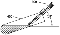
- the center axis of the capillary of the sampling device is at a certain angle with the center axis of the clamp arm. When the sampler is placed in the sample tube 400 to sample the sample, the center axis of the capillary is at 50° from the horizontal plane.
- the sampler When the sample tube 300 is inserted into the sample tube 400 to aspirate the sample, it is relatively smooth, and the sample tube 400 only needs to be tilted slightly so that the capillary tube can absorb the sample, and parts other than the capillary tube will not be stained with the sample.
- the sampler with the capillary tube parallel to the central axis of the clamp arm of Example 1 is used to sample in the sample tube.
- the central axis of the capillary is at 50° from the horizontal plane.
- the sample tube needs to be inclined at a large angle, and even the sample tube is almost parallel to the ground to take a sample. At this time, the sample is easier to spill from the sample tube.
- the capillary and the clamping arm have a certain angle, and the angle between the direction of solution washing and the capillary becomes smaller, which makes the sample in the capillary easier to elute, and the sample elution time is also reduced.
- a limit device on the handle can restrict the sampler from being placed in the detection box only in one direction, and limit the tilting angle of the sampling device when it is placed in the detection box.
- the limit device can be set as a vertical rib or a polyhedral platform.
- the limiting device can also be configured as a vertical rib as shown in FIG. 24A or a polyhedral platform as shown in FIG. 24B.
- the limiting device shown in Fig. 14A extends upward to the upper end of the handle on the basis of Fig. 24A.
- a boss 202 is provided on one side of the opening of the sample adding groove 201 of the detection box.
- a limit device 306 is added to the handle. The limit device only allows the sampler 300 to be inserted into the detection box 200 in the direction shown in Figure 21. When the sampler is inserted into the detection box in the direction shown in Figure 20, the limit device 306 will be projected by the sample slot 201. Station 202 is stuck.
- the limit device reduces the tiltable angle of the sampler when it is placed in the detection box.
- its tiltable angles to the left and right directions in the sample adding groove are 10° and 15°, respectively, as shown in Figure 22A and Figure 22B.
- the tiltable angle in the left and right directions is reduced to 2° and 8°, respectively, as shown in Figure 23A and Figure 23B.
Landscapes
- Health & Medical Sciences (AREA)
- Chemical & Material Sciences (AREA)
- Life Sciences & Earth Sciences (AREA)
- Analytical Chemistry (AREA)
- General Health & Medical Sciences (AREA)
- Hematology (AREA)
- Immunology (AREA)
- Chemical Kinetics & Catalysis (AREA)
- Clinical Laboratory Science (AREA)
- Pathology (AREA)
- General Physics & Mathematics (AREA)
- Biochemistry (AREA)
- Physics & Mathematics (AREA)
- Engineering & Computer Science (AREA)
- Hydrology & Water Resources (AREA)
- Urology & Nephrology (AREA)
- Molecular Biology (AREA)
- Biomedical Technology (AREA)
- Food Science & Technology (AREA)
- Medicinal Chemistry (AREA)
- Microbiology (AREA)
- Cell Biology (AREA)
- Biotechnology (AREA)
- Sampling And Sample Adjustment (AREA)
- Investigating Or Analysing Biological Materials (AREA)
Abstract
L'invention concerne un dispositif d'échantillonnage comprenant une poignée (1) et un collecteur. Le collecteur est relié à la poignée (1). Le collecteur possède une fonction capillaire et est apte à aspirer automatiquement un réactif ou échantillon liquide. Le dispositif d'échantillonnage est apte à absorber rapidement, commodément et quantitativement une quantité requise du réactif ou échantillon, ce qui est commode pour la production et la fabrication, et peut réaliser un échantillonnage micro-quantitatif. Le réactif est stocké dans le collecteur du dispositif d'échantillonnage sous la forme d'une poudre sèche, ce qui permet d'obtenir un conditionnement en portion individuelle du réactif de détection.
Priority Applications (2)
| Application Number | Priority Date | Filing Date | Title |
|---|---|---|---|
| US17/631,729 US12467830B2 (en) | 2019-08-01 | 2020-07-31 | Sampling device and detection box |
| EP20845993.3A EP4009030A4 (fr) | 2019-08-01 | 2020-07-31 | Dispositif d'échantillonnage et boîtier de détection |
Applications Claiming Priority (2)
| Application Number | Priority Date | Filing Date | Title |
|---|---|---|---|
| CN201910706447.3 | 2019-08-01 | ||
| CN201910706447 | 2019-08-01 |
Publications (1)
| Publication Number | Publication Date |
|---|---|
| WO2021018300A1 true WO2021018300A1 (fr) | 2021-02-04 |
Family
ID=74228962
Family Applications (1)
| Application Number | Title | Priority Date | Filing Date |
|---|---|---|---|
| PCT/CN2020/106388 Ceased WO2021018300A1 (fr) | 2019-08-01 | 2020-07-31 | Dispositif d'échantillonnage et boîtier de détection |
Country Status (4)
| Country | Link |
|---|---|
| US (1) | US12467830B2 (fr) |
| EP (1) | EP4009030A4 (fr) |
| CN (6) | CN213301769U (fr) |
| WO (1) | WO2021018300A1 (fr) |
Families Citing this family (3)
| Publication number | Priority date | Publication date | Assignee | Title |
|---|---|---|---|---|
| CN213301769U (zh) * | 2019-08-01 | 2021-05-28 | 利多(香港)有限公司 | 单人份质控品的保存装置 |
| CN117244602B (zh) * | 2023-09-28 | 2024-05-24 | 康容生物科技(太仓)有限公司 | 一种一体成型外置活塞移液器吸头 |
| CN117517648A (zh) * | 2023-10-26 | 2024-02-06 | 郑州伊美诺生物技术有限公司 | 一种胶体金用羊抗鼠二抗保存缓冲液 |
Citations (8)
| Publication number | Priority date | Publication date | Assignee | Title |
|---|---|---|---|---|
| JPS6378043A (ja) * | 1986-09-19 | 1988-04-08 | Matsushita Electric Works Ltd | 液中成分測定装置 |
| US5162237A (en) | 1988-04-11 | 1992-11-10 | Miles Inc. | Reaction cassette for preforming sequential analytical assays by noncentrifugal and noncapillary manipulations |
| US5833630A (en) * | 1994-11-03 | 1998-11-10 | Kloth; Bernd | Sample collection device |
| JP2008011880A (ja) * | 2006-06-30 | 2008-01-24 | Sakae:Kk | 液体採取具 |
| CN202204706U (zh) * | 2011-08-12 | 2012-04-25 | 石家庄禾柏生物技术股份有限公司 | 一体化样本采集加注器 |
| WO2013010333A1 (fr) * | 2011-07-21 | 2013-01-24 | 瑞基海洋生物科技股份有限公司 | Procédé de réaction de polymérase en chaîne par transcription inverse |
| CN104918703A (zh) * | 2012-12-28 | 2015-09-16 | 阿赛斯生物股份有限公司 | 移液管 |
| WO2017005122A1 (fr) | 2015-07-03 | 2017-01-12 | 艾康生物技术(杭州)有限公司 | Système de test |
Family Cites Families (16)
| Publication number | Priority date | Publication date | Assignee | Title |
|---|---|---|---|---|
| GB1111583A (en) * | 1965-05-18 | 1968-05-01 | Nat Res Dev | Improvements in or relating to liquid-dispensing apparatus |
| US4441373A (en) * | 1979-02-21 | 1984-04-10 | American Hospital Supply Corporation | Collection tube for drawing samples of biological fluids |
| AU2003217369A1 (en) * | 2002-02-08 | 2003-09-02 | Amersham Biosciences (Sv) Corporation | Method and apparatus for performing submicroliter reactions with nucleic acids or proteins |
| US20070031293A1 (en) | 2005-08-04 | 2007-02-08 | Beatty Christopher C | Method and apparatus for collecting and diluting a liquid sample |
| US20090209882A1 (en) * | 2008-02-15 | 2009-08-20 | Trinity Research Limited | Integrated cap and sample applicator |
| JP2012026997A (ja) * | 2010-07-22 | 2012-02-09 | Aska Special Laboratory Co Ltd | 毛細管による微量検体採取・希釈・分注方法及び器具 |
| TWI484182B (zh) * | 2012-11-07 | 2015-05-11 | Taidoc Technology Corp | 反應容器、分析裝置及分析方法 |
| DK2848309T3 (da) * | 2013-09-13 | 2020-09-07 | Nanotemper Tech Gmbh | Bærer til kapillarrør |
| CN104475181A (zh) * | 2014-12-16 | 2015-04-01 | 重庆跃发日用品有限公司 | 固态试剂夹持装置 |
| CN105013546B (zh) * | 2015-07-03 | 2017-12-08 | 艾康生物技术(杭州)有限公司 | 生物样品反应盒 |
| CA2992596C (fr) * | 2015-07-17 | 2023-08-22 | Cue Inc. | Systemes et procedes pour la detection amelioree et la quantification de substances a analyser |
| CN204924717U (zh) * | 2015-08-24 | 2015-12-30 | 三诺生物传感股份有限公司 | 一种样本检测装置及其取样器 |
| CN109416303A (zh) * | 2016-07-06 | 2019-03-01 | 尼普洛株式会社 | 标本收集尖端、标本制备容器和标本制备套件 |
| KR101723025B1 (ko) * | 2016-10-12 | 2017-04-07 | 주식회사 아이센스 | 장기 안정성이 향상된 시료를 포함하는 당화혈색소 정량분석용 키트 |
| EP3821056B1 (fr) | 2018-07-13 | 2024-03-13 | Siemens Healthcare Diagnostics, Inc. | Indicateur de détection de dosage de microalbumine créatinine et procédé de production et d'utilisation associés |
| CN213301769U (zh) | 2019-08-01 | 2021-05-28 | 利多(香港)有限公司 | 单人份质控品的保存装置 |
-
2020
- 2020-05-01 CN CN202020709096.XU patent/CN213301769U/zh active Active
- 2020-05-01 CN CN202010368350.9A patent/CN112304699A/zh active Pending
- 2020-05-01 CN CN202010368575.4A patent/CN112295628A/zh active Pending
- 2020-07-31 CN CN202123277594.5U patent/CN218121485U/zh active Active
- 2020-07-31 CN CN202010761874.4A patent/CN112304700A/zh active Pending
- 2020-07-31 EP EP20845993.3A patent/EP4009030A4/fr active Pending
- 2020-07-31 WO PCT/CN2020/106388 patent/WO2021018300A1/fr not_active Ceased
- 2020-07-31 CN CN202021567088.2U patent/CN215573985U/zh active Active
- 2020-07-31 US US17/631,729 patent/US12467830B2/en active Active
Patent Citations (8)
| Publication number | Priority date | Publication date | Assignee | Title |
|---|---|---|---|---|
| JPS6378043A (ja) * | 1986-09-19 | 1988-04-08 | Matsushita Electric Works Ltd | 液中成分測定装置 |
| US5162237A (en) | 1988-04-11 | 1992-11-10 | Miles Inc. | Reaction cassette for preforming sequential analytical assays by noncentrifugal and noncapillary manipulations |
| US5833630A (en) * | 1994-11-03 | 1998-11-10 | Kloth; Bernd | Sample collection device |
| JP2008011880A (ja) * | 2006-06-30 | 2008-01-24 | Sakae:Kk | 液体採取具 |
| WO2013010333A1 (fr) * | 2011-07-21 | 2013-01-24 | 瑞基海洋生物科技股份有限公司 | Procédé de réaction de polymérase en chaîne par transcription inverse |
| CN202204706U (zh) * | 2011-08-12 | 2012-04-25 | 石家庄禾柏生物技术股份有限公司 | 一体化样本采集加注器 |
| CN104918703A (zh) * | 2012-12-28 | 2015-09-16 | 阿赛斯生物股份有限公司 | 移液管 |
| WO2017005122A1 (fr) | 2015-07-03 | 2017-01-12 | 艾康生物技术(杭州)有限公司 | Système de test |
Non-Patent Citations (1)
| Title |
|---|
| See also references of EP4009030A4 |
Also Published As
| Publication number | Publication date |
|---|---|
| CN213301769U (zh) | 2021-05-28 |
| EP4009030A4 (fr) | 2023-08-02 |
| CN112295628A (zh) | 2021-02-02 |
| CN112304700A (zh) | 2021-02-02 |
| US12467830B2 (en) | 2025-11-11 |
| US20220276132A1 (en) | 2022-09-01 |
| EP4009030A1 (fr) | 2022-06-08 |
| CN215573985U (zh) | 2022-01-18 |
| CN218121485U (zh) | 2022-12-23 |
| CN112304699A (zh) | 2021-02-02 |
Similar Documents
| Publication | Publication Date | Title |
|---|---|---|
| CN1902484B (zh) | 一次性流体试样采集装置 | |
| KR101136654B1 (ko) | 시료채취 및 분석 기구 | |
| CN218121485U (zh) | 一种检测盒 | |
| US8367023B2 (en) | Reagent vessel | |
| JP2021120681A (ja) | 拭い取りを受け取るための機器、システム、方法及びキット | |
| CN1720168B (zh) | 液体保存容器以及容器架 | |
| BR0209540B1 (pt) | Aparelho, cartucho e dispositivo de exame e uso do aparelho de exame | |
| JP6522556B2 (ja) | 血液検査キット、及びそれを用いた分析方法 | |
| JP2019502103A (ja) | アッセイ装置 | |
| JP6763400B2 (ja) | 採便器、便検体中の成分の測定方法、便検体中の成分の安定化方法、及び、便検体の保存方法 | |
| CN104914253B (zh) | 一种纤维蛋白原的检测方法 | |
| JP6246132B2 (ja) | 検体検査装置 | |
| WO2018124275A1 (fr) | Kit d'analyse sanguine et méthode d'analyse sanguine | |
| US20210239717A1 (en) | Microsampling detection in diabetes | |
| WO2017006963A1 (fr) | Kit de test sanguin et procédé d'analyse l'utilisant | |
| ES2982958T3 (es) | Dispositivo de separación y/o conservación de un biofluido en un punto de atención, kit y procedimiento para identificar una enfermedad | |
| JP2023550497A (ja) | ヘモグロビン補正装置を用いた改良型elisa、及びその方法 | |
| CN119901915B (zh) | 一种血液检测装置及其使用方法 | |
| CN205719993U (zh) | 一种用于收集并检测样本的装置 | |
| HK40048617A (en) | Microsampling detection in diabetes |
Legal Events
| Date | Code | Title | Description |
|---|---|---|---|
| 121 | Ep: the epo has been informed by wipo that ep was designated in this application |
Ref document number: 20845993 Country of ref document: EP Kind code of ref document: A1 |
|
| NENP | Non-entry into the national phase |
Ref country code: DE |
|
| ENP | Entry into the national phase |
Ref document number: 2020845993 Country of ref document: EP Effective date: 20220301 |
|
| WWG | Wipo information: grant in national office |
Ref document number: 17631729 Country of ref document: US |