WO2021019637A1 - Dispositif de sécurité, dispositif serveur, système de sécurité et procédé de réglage de fonction de sécurité - Google Patents
Dispositif de sécurité, dispositif serveur, système de sécurité et procédé de réglage de fonction de sécurité Download PDFInfo
- Publication number
- WO2021019637A1 WO2021019637A1 PCT/JP2019/029628 JP2019029628W WO2021019637A1 WO 2021019637 A1 WO2021019637 A1 WO 2021019637A1 JP 2019029628 W JP2019029628 W JP 2019029628W WO 2021019637 A1 WO2021019637 A1 WO 2021019637A1
- Authority
- WO
- WIPO (PCT)
- Prior art keywords
- security
- power consumption
- unit
- setting
- server device
- Prior art date
- Legal status (The legal status is an assumption and is not a legal conclusion. Google has not performed a legal analysis and makes no representation as to the accuracy of the status listed.)
- Ceased
Links
Images




Classifications
-
- B—PERFORMING OPERATIONS; TRANSPORTING
- B60—VEHICLES IN GENERAL
- B60R—VEHICLES, VEHICLE FITTINGS, OR VEHICLE PARTS, NOT OTHERWISE PROVIDED FOR
- B60R16/00—Electric or fluid circuits specially adapted for vehicles and not otherwise provided for; Arrangement of elements of electric or fluid circuits specially adapted for vehicles and not otherwise provided for
- B60R16/02—Electric or fluid circuits specially adapted for vehicles and not otherwise provided for; Arrangement of elements of electric or fluid circuits specially adapted for vehicles and not otherwise provided for electric constitutive elements
-
- G—PHYSICS
- G06—COMPUTING OR CALCULATING; COUNTING
- G06F—ELECTRIC DIGITAL DATA PROCESSING
- G06F21/00—Security arrangements for protecting computers, components thereof, programs or data against unauthorised activity
- G06F21/50—Monitoring users, programs or devices to maintain the integrity of platforms, e.g. of processors, firmware or operating systems
- G06F21/55—Detecting local intrusion or implementing counter-measures
-
- H—ELECTRICITY
- H04—ELECTRIC COMMUNICATION TECHNIQUE
- H04L—TRANSMISSION OF DIGITAL INFORMATION, e.g. TELEGRAPHIC COMMUNICATION
- H04L9/00—Cryptographic mechanisms or cryptographic arrangements for secret or secure communications; Network security protocols
- H04L9/14—Cryptographic mechanisms or cryptographic arrangements for secret or secure communications; Network security protocols using a plurality of keys or algorithms
- H04L9/16—Cryptographic mechanisms or cryptographic arrangements for secret or secure communications; Network security protocols using a plurality of keys or algorithms the keys or algorithms being changed during operation
Definitions
- the present invention relates to a security device, a server device, a security system, and a security function setting method.
- Patent Document 1 discloses an in-vehicle network management system configured by connecting an abnormality detection server (cloud server) and a plurality of vehicles via a network.
- Each vehicle is equipped with a plurality of electronic control units (ECUs) connected by a bus and a gateway device.
- the gateway device includes a frame transmission / reception unit, a frame interpretation unit, a fraudulent frame detection unit, a rule holding unit, a key processing unit, a key holding unit, a frame upload unit, a fraud detection reporting unit, an update processing unit, and the like.
- the abnormality detection server is configured to include a communication unit, an authentication processing unit, a log collection processing unit, a log analysis processing unit, a security information generation unit, and the like.
- each vehicle transmits log information including frame information to the abnormality detection server.
- the abnormality detection server performs processing such as calculation of the frame abnormality degree based on the log information received from each vehicle, determines the alert level according to the calculated abnormality degree, and corresponds to the determined alert level.
- an alert notification or the like is transmitted to one or more vehicles. As a result, it is possible to call the driver or the like of the vehicle to pay attention to the abnormality, or to control the vehicle to shift to a safer state.
- the present invention has been made in view of the above problems, and provides a security device, a server device, a security system, and a security function setting method capable of suppressing power consumption related to the security function while maintaining the security function.
- the purpose is to do.
- the security device (1) is a security mounted on the mobile body in a security system including a server device and a mobile body capable of communicating with the server device. It ’s a device, A state information acquisition unit that acquires state information including the state of the self-moving object, An operation setting determination unit that determines the operation settings of each of the security functions shared by the security device and the server device according to the acquired state information. Based on the determined operation setting, the first setting unit that enables or disables each security function of the security device, and It is characterized in that it includes a sharing notification unit that gives a sharing notification to the server device for enabling or invalidating each of the security functions of the server device based on the determined operation setting.
- the operation settings (for example) of the security functions shared by the security device and the server device according to the acquired state information (in other words, the state of the self-moving body). , Valid or invalid) is determined.
- each security function of the security device is enabled or disabled based on the determined operation setting.
- the sharing notification is sent to the server device. Therefore, it is possible to assign at least a part of the security function of the security device to the server device according to the state of the self-moving body, and the security function for ensuring the safety of the security system as a whole. It is possible to suppress the power consumption related to the security function in the mobile body while maintaining the above.
- the moving body includes, but is not limited to, for example, a vehicle traveling on a road and an automatic guided vehicle used in a factory as an industrial device.
- the security device (2) is the security device (1), in which the state of one or more self-moving objects and the operation settings of the security functions shared by the security device and the server device. Equipped with a setting information storage unit that stores setting information including relationships
- the operation setting determination unit It is characterized in that it includes a first determination unit that determines the operation setting of each of the security functions corresponding to the state of the self-moving body indicated by the acquired state information from the setting information.
- the setting information is stored in the setting information storage unit, and the operation setting determination unit obtains the state information from the setting information.
- the operation setting determination unit obtains the state information from the setting information.
- the security device (3) is the above-mentioned security device (1) or (2).
- the operation setting determination unit Among the security functions of the security device, based on the total power consumption of the functions whose operation is effectively set and the allowable power consumption of the security function in the state of the self-moving object indicated by the acquired state information. It is characterized in that it includes a second determination unit that determines the operation settings of each of the security functions.
- the security device is such that the total power consumption is equal to or less than the allowable power consumption according to the allowable power consumption of the security function in the state of the self-moving body. It is possible to enable or disable each of the security functions in the above, to give flexibility in determining the operation setting, and to appropriately consume power related to the security function in the moving body. It can be suppressed.
- the security device (4) is the permissible power consumption information including the relationship between the state of one or more self-moving objects and the permissible power consumption of the security function of the security device in the security device (3).
- Allowable power consumption information storage unit to store It is equipped with a power consumption information storage unit that stores power consumption information including the relationship between the power consumption and priority of each security function of the security device.
- the second decision unit From the permissible power consumption information, the permissible power consumption of the security function corresponding to the state of the self-moving body indicated by the acquired state information is acquired.
- the operation setting of each of the security functions is determined by comparing the acquired allowable power consumption with the total power consumption of the functions of the security functions included in the power consumption information for which the operation is effectively set. It is characterized by being something to do.
- the security device (4) among the allowable power consumption acquired by the second determination unit and the security function included in the power consumption information, the power consumption of the function whose operation is effectively set. Is compared with the total of the above, and the operation setting (for example, whether to enable or disable) of each of the security functions is determined.
- the permissible power consumption information and the power consumption information it is possible to reduce the processing load of the second determination unit and to speed up the processing performed by the second determination unit.
- the security device (4) when the second determination unit makes the comparison and the total power consumption is equal to or more than the acquired allowable power consumption. It is characterized in that the decision is made to invalidate the low-priority function from the security functions whose operation is effectively set.
- the security device (5) when the total value of the power consumption is equal to or more than the acquired allowable power consumption as a result of the comparison by the second determination unit, the operation is effectively set. A decision is made to disable the low priority function among the security functions. As a result, the state in which the high-priority function is effectively set can be maintained, and the security function can be switched and set so as not to exceed the allowable power consumption, and the allowable power consumption is taken into consideration. In addition, the security function can be set so that the power consumption is appropriate.
- the security device (4) when the total value of the power consumption is less than the acquired allowable power consumption as a result of the comparison by the second determination unit.
- the security function whose operation is set to be invalid is determined to enable the function having a high priority.
- the security device (6) when the total value of the power consumption is less than the acquired allowable power consumption as a result of the comparison by the second determination unit, the operation is invalidated. A decision is made to enable the high priority function from the security functions. As a result, when the allowable power consumption is less than the allowable power consumption, the security function can be switched and set so that the high priority function is effectively set, and the allowable power consumption is taken into consideration. The security function can be set so that the power consumption is appropriate.
- the state of the self-moving body is parked, started, running or stopped, and under maintenance. It is characterized by including one of the states.
- the state of the self-moving body is shared between the security device and the server device according to the state of being parked, started, running, stopped, or being maintained. It is possible to switch the operation setting of each of the security functions. Therefore, the security function in the self-moving body can be switched to a setting capable of enhancing the power consumption suppressing effect according to the dynamics of the self-moving body. Further, the server device can be assigned the security function so that the protection function by the security function can be maintained or strengthened according to the dynamics of the self-moving body.
- the security device (8) is characterized in that, in any of the security devices (1) to (6), the state of the self-moving body includes the power state of the power supply unit of the self-moving body. It is said.
- the security device depends on the power state of the power supply unit of the self-moving body, for example, the state of the remaining power amount, or the state of the setting mode (for example, eco mode) related to the power. It is possible to switch the operation setting of each of the security functions shared by the server device and the server device. Therefore, when the power consumption related to the security function of the mobile body is desired to be further suppressed, the operation setting can be switched to the operation setting capable of enhancing the power consumption suppressing effect. Further, the server device can be assigned the security function so that the protection function by the security function can be maintained or strengthened according to the power state of the self-moving body.
- the security device (9) is the security device (1) to (8) described above.
- the security function An internal communication encryption unit that encrypts the internal communication of the mobile body, An authentication unit that certifies the locking or unlocking of the self-moving body, An access control unit that determines the access right to the internal equipment of the self-moving body, It is characterized by including one of a function of an intrusion detection unit that detects an intrusion due to a security attack on the self-moving body and a log recording unit that records an operation log of the self-moving body.
- the security device (9) as the security function shared by the security device and the server device according to the state of the self-moving body, the internal communication encryption unit, the authentication unit, the access control unit, and the like. It is possible to switch the operation setting (for example, the setting for enabling or disabling) of at least one of the intrusion detection unit and the log recording unit. Therefore, depending on the state of the self-moving body, it is possible to appropriately balance the maintenance of the protection function by the security function shared by the moving body and the server device and the suppression of the power consumption related to the security function. it can.
- the server device (1) is a server device capable of communicating with a mobile body equipped with any of the above security devices (1) to (9).
- a sharing notification acquisition unit that acquires a sharing notification from the mobile body for enabling or disabling each security function of the server device. It is characterized in that it includes a second setting unit that enables or disables each of the security functions of the server device based on the acquired notification of sharing.
- the security function executed by the server device is executed. It is possible to switch the operation setting of the above based on the sharing notification. Therefore, by bearing the security function according to the state of the self-moving body, the security system maintains the security function for ensuring safety, and consumes the moving body related to the security function. Power can be suppressed.
- the server device (2) includes a setting completion notification unit that notifies the mobile body of the completion of the setting when the setting by the second setting unit is completed in the server device (1). It is characterized by.
- the mobile body when the setting by the second setting unit is completed, the mobile body is notified of the completion of the setting, so that the mobile body has completed the setting of the security function on the server device. You can confirm that.
- the security system is configured to include a mobile body equipped with any of the security devices (1) to (9) and the server device (1) or (2). It is a feature.
- the effect of any one of the security devices (1) to (9) and the server device (1) or (2) can be obtained, and the security system as a whole is based on the security function. While maintaining the protection function, it is possible to suppress the power consumption related to the security function in the moving body, and it is possible to achieve both the maintenance of the protection function by the security function and the suppression of the power consumption related to the security function. You can build a system.
- the security function setting method is a security function setting method in a security system including a server device and a mobile body capable of communicating with the server device.
- the security device mounted on the mobile body
- the state information acquisition step to acquire the state information including the state of the self-moving object, and
- An operation setting determination step for determining the operation settings of each of the security functions shared by the security device and the server device according to the acquired state information, and
- a first setting step for enabling or disabling each of the security functions of the security device based on the determined operation setting, and Including a sharing notification step of giving a sharing notification to the server device for enabling or invalidating each of the security functions of the server device based on the determined operation setting.
- the server device The sharing notification acquisition step of acquiring the sharing notification from the moving body, and It is characterized by including a second setting step of setting each of the security functions of the server device to be valid or invalid based on the acquired notification of sharing.
- the security function setting method the operation settings (for example, valid and invalid) of the security function shared by the security device and the server device according to the acquired state information, that is, the state of the self-moving body. Which one to set) is decided. Then, each security function of the security device is enabled or disabled based on the determined operation setting. Further, based on the determined operation setting, the sharing notification is sent to the server device. Therefore, it is possible to assign at least a part of the security function of the security device to the server device according to the state of the self-moving body, and the security function for ensuring the safety of the security system as a whole. It is possible to suppress the power consumption related to the security function in the mobile body while maintaining the above.
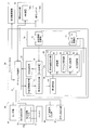
- FIG. 1 is a schematic diagram for explaining an example of a security system to which the security device and the server device according to the embodiment (1) are applied.
- the security system 1 includes a server device 2 and one or more vehicles 4 capable of communicating with the server device 2 via the communication network 3.
- the vehicle 4 is an example of the "moving body" of the present invention.
- the type of vehicle 4 is not particularly limited.
- the security system 1 detects an abnormality that has occurred in the vehicle 4 in at least one of the vehicle 4 and the server device 2, and based on the detected abnormality, an in-vehicle system by an external attack (also referred to as a security attack or a cyber attack). This is a system for preventing an attack on a vehicle 4 and maintaining the security of the vehicle 4 by detecting an intrusion into the 40 and performing incident response processing for the attack.
- the server device 2 includes a communication unit 10, a control unit 11, and a storage unit 12.
- the server device 2 is, for example, monitored and operated by a predetermined security countermeasure organization 13, such as detecting an intrusion due to an attack on the vehicle 4, instructing an incident response to the vehicle 4, and the vehicle 4. It is equipped with one or more security functions that perform processing such as recording log data obtained from.
- the server device 2 is an example of the "server device" of the present invention.
- the server device 2 may be configured by a cloud server composed of one or more server groups that can be accessed via the communication network 3.
- the communication network 3 is a mobile phone network including a base station, a wireless communication network such as a wireless LAN (Local Area Network), an Internet, a road-to-vehicle communication network, a vehicle-to-vehicle communication network, a wired communication network such as a public telephone network, or a dedicated network. It may be configured to include various telecommunications lines such as.
- a wireless communication network such as a wireless LAN (Local Area Network), an Internet, a road-to-vehicle communication network, a vehicle-to-vehicle communication network, a wired communication network such as a public telephone network, or a dedicated network. It may be configured to include various telecommunications lines such as.
- the vehicle 4 is equipped with an in-vehicle system 40.
- the in-vehicle system 40 is an in-vehicle network system, and is a diagnostic device connection unit 41, a sensor group 42, a traveling system ECU (Electronic Control Unit) group 43, a driving support system ECU group 44, a body system ECU group 45, and an information system ECU group 46.
- a gateway ECU 50 are included, and these are connected via a bus which is a communication path.
- the gateway ECU 50 is an example of the “security device” of the present invention.
- the in-vehicle system 40 is composed of, for example, a network that communicates according to the CAN (Controller Area Network) protocol.
- a communication standard other than CAN may be adopted for the in-vehicle system 40.
- the traveling system ECU group 43, the driving support system ECU group 44, the body system ECU group 45, and the information system ECU group 46 (hereinafter, these are also collectively referred to as an ECU group) are control devices mounted on the vehicle 4.
- the gateway ECU 50 has a gateway function that performs processing such as passing (transferring) a frame (message) with each ECU group included in the in-vehicle system 40 according to the CAN protocol, and detects intrusion due to an attack on the in-vehicle system 40. It has one or more security functions that perform processing such as protection.
- the gateway device installed in the conventional in-vehicle system was configured to always operate multiple security functions regardless of the state of the vehicle in order to ensure the safety of the in-vehicle network. Therefore, even if it is desired to suppress the power consumption related to the security function, the power consumption cannot be suppressed. On the other hand, if the security function is blindly disabled (stops operation) in order to suppress the power consumption, the attack cannot be detected and the protection function of the in-vehicle system is lowered. Therefore, it was not possible to achieve both the maintenance of the protection function by the security function and the reduction of the power consumption related to the security function.
- the security system 1 adopts the following configuration in order to maintain the protection function of the in-vehicle system 40 by the security function and suppress the power consumption related to the security function. did.
- the gateway ECU 50 acquires state information including the state of its own vehicle (self-moving body) from any of the diagnostic device connection unit 41, the sensor group 42, or the ECU group, and the gateway responds to the acquired state information.
- a process of determining the operation setting (for example, whether to enable or disable) of one or more security functions shared by the ECU 50 and the server device 2 is performed. Then, based on the determined operation setting, the processing for setting each of the security functions of the gateway ECU 50 to be valid or invalid is performed, and the server sends a shared notification for setting each of the security functions of the server device 2 to be valid or invalid. This is performed for the device 2.
- the state information is, for example, information indicating at least one of a state in which the own vehicle is parked, a state in which the vehicle is starting, a state in which the vehicle is running or stopped, and a state in which the vehicle is under maintenance. It may be information indicating the power state of the power supply unit of the own vehicle, for example, the state such as the remaining power amount of the battery.
- the in-vehicle communication encryption unit that encrypts the in-vehicle communication (internal communication) of the own vehicle
- the authentication unit that authenticates the locking or unlocking of the own vehicle
- the in-vehicle equipment (internal equipment) of the own vehicle. It may include at least one of an access control unit for determining access rights, an intrusion detection unit for detecting intrusion by a security attack on the own vehicle, and a log recording unit for recording the operation log of the own vehicle.
- the server device 2 performs a process of acquiring the sharing notification for enabling or invalidating each of the security functions of the server device 2 from the vehicle 4, and based on the acquired sharing notification, the server device 2 Performs processing to enable or disable each security function.
- the operation settings of the security functions shared by the gateway ECU 50 and the server device 2 are determined according to the state of the own vehicle. Then, each security function of the security device is enabled or disabled based on the determined operation setting. Further, based on the determined operation setting, the sharing notification is sent to the server device. On the other hand, in the server device 2, the security functions of the server device 2 are set to be enabled or disabled based on the allotted notification obtained from the vehicle 4.
- the vehicle 4 at least a part of the security function of the gateway ECU 50 can be shared by the server device 2 according to the state of the own vehicle, and in the server device 2, the vehicle 4 can be assigned according to the state of the vehicle 4. It is possible to bear at least a part of the security function of. Therefore, as the entire security system 1, it is possible to suppress the power consumption related to the security function in the vehicle 4 while maintaining the protection function of the in-vehicle system 40 by the security function, and maintain the protection function by the security function and the security function. It is possible to achieve both the reduction of power consumption related to the above.
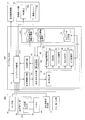
- FIG. 2 is a block diagram showing a functional configuration example of an in-vehicle system 40 equipped with the gateway ECU 50 according to the embodiment (1).
- the in-vehicle system 40 includes a diagnostic device connection unit 41, a sensor group 42, a traveling system ECU group 43, a driving support system ECU group 44, a body system ECU group 45, an information system ECU group 46, and a gateway ECU 50. ..
- the traveling system ECU group 43, the driving support system ECU group 44, the body system ECU group 45, the information system ECU group 46, and the gateway ECU 50 are composed of a computer device including one or more processors, a memory, a communication module, and the like. There is. Then, the processor mounted on each ECU reads the program stored in the memory, interprets and executes the program, and the predetermined control is executed by each ECU.
- the diagnostic machine connection unit 41 is a diagnostic connector device provided with a port to which a diagnostic machine or a scan tool for performing failure diagnosis or maintenance is connected.
- a diagnostic connector device provided with a port to which a diagnostic machine or a scan tool for performing failure diagnosis or maintenance is connected.
- OBDII On-board diagnostics II connector. It is composed of.
- the sensor group 42 includes various in-vehicle sensors that acquire sensing data used for control performed by the traveling system ECU group 43, the driving support system ECU group 44, and the like.
- a vehicle speed sensor a shift position sensor, an accelerator opening sensor, an obstacle detection sensor such as a millimeter wave radar, an image acquisition sensor such as a camera, and the like are included.
- the traveling system ECU group 43 includes a drive system ECU, a chassis system ECU, and the like.
- the drive system ECU includes control units related to "running" functions such as engine control, motor control, fuel cell control, EV (Electric Vehicle) control, and transmission control.
- the chassis-based ECU includes a control unit related to a "stop / turn” function such as brake control or steering control.
- the traveling system ECU group 43 includes a power monitoring unit 43a for monitoring the power state such as the remaining power amount of the battery 47 (power supply unit) of the vehicle 4, and the power state from the power monitoring unit 43a to the gateway ECU 50. Is sent.
- the electric power state may be, for example, a state of remaining electric energy, a state of a setting mode related to electric power (for example, an eco mode), or the like.
- the driving support system ECU group 44 includes an automatic braking support function, a lane keeping support function (also called LKA / Lane Keep Assist), a constant speed driving / inter-vehicle distance support function (also called ACC / Adaptive Cruise Control), and a forward collision warning function. , Lane departure warning function, blind spot monitoring function, traffic sign recognition function, driver monitoring function, etc., functions that automatically improve safety or realize comfortable driving by linking with the driving system ECU group 43, etc. (driving support function) , Or an automatic operation function), and at least one control unit is included.
- a lane keeping support function also called LKA / Lane Keep Assist
- ACC / Adaptive Cruise Control constant speed driving / inter-vehicle distance support function
- forward collision warning function Lane departure warning function, blind spot monitoring function, traffic sign recognition function, driver monitoring function, etc., functions that automatically improve safety or realize comfortable driving by linking with the driving system ECU group 43, etc. (driving support function) , Or an automatic operation function
- the driving support system ECU group 44 includes, for example, Level 1 (driver assistance), Level 2 (partially automatic driving), and Level 3 (conditional automatic driving) at the automatic driving level presented by the American Society of Automotive Engineers of Japan (SAE). It may be equipped with the function of (driving). Furthermore, the functions of level 4 (highly automatic driving) and level 5 (fully automatic driving) of the automatic driving level may be equipped, and the functions of only level 1 and 2 or only level 2 and 3 are equipped. You may.
- Level 1 driver assistance
- Level 2 partially automatic driving
- Level 3 conditional automatic driving
- SAE American Society of Automotive Engineers of Japan
- the body system ECU group 45 includes at least one control unit related to the function of the vehicle body such as a door lock, a smart key, a power window, an air conditioner, a light, an instrument panel, or a winker.
- the information system ECU group 46 includes an infotainment device, a telematics device, or an ITS (Intelligent Transport Systems) related device.
- the infotainment device includes an HMI (Human Machine Interface) device 46a that functions as a user interface, a car navigation device, an audio device, and the like, and the telematics device communicates with a server device 2 and the like via a communication network 3.
- a communication unit 46b and the like for this purpose are included.
- the ITS-related device includes an ETC (Electronic Toll Collection System), a communication unit for performing road-to-vehicle communication with a roadside machine such as an ITS spot, or an inter-vehicle communication.
- ETC Electronic Toll Collection System
- the gateway ECU 50 includes a gateway function unit 51, a security control unit 52, and a storage unit 70.
- the gateway function unit 51 has a function of controlling transfer of a frame (message) via each ECU group and a bus.
- a frame transmission / reception unit, a frame interpretation unit, a frame conversion unit, etc. (not shown) are mounted on a vehicle.
- a configuration necessary for mutual communication with each ECU group of the system 40 according to the CAN protocol is included.
- the security control unit 52 includes a status information acquisition unit 53, an operation setting determination unit 54, a first setting unit 55, a division notification unit 56, and a security function unit 60.
- the security control unit 52 includes a memory including a ROM (Read Only Memory), a RAM (Random Access Memory), etc., in which a program executed in each of the above units is stored, and a CPU (CPU) that reads and executes the program from the memory. It is configured to include processors such as Central Processing Unit), and the functions of the above parts are realized by the cooperation of these hardware and programs.
- ROM Read Only Memory
- RAM Random Access Memory
- CPU Central Processing Unit
- the storage unit 70 is configured to include a setting information storage unit 71 and a log data storage unit 72, and is composed of, for example, a semiconductor memory such as a flash memory.
- the state information acquisition unit 53 performs a process of acquiring state information including the state of the own vehicle (vehicle 4) from any of the diagnostic device connection unit 41, the sensor group 42, or each ECU group via the gateway function unit 51. ..
- the state information to be acquired is, for example, at least one of a state in which the own vehicle is parked, a state in which the vehicle is starting, a state in which the vehicle is running or stopped, and a state in which the vehicle is under maintenance (vehicle 4). This is information indicating the dynamics).
- a lock state signal acquired from the smart key unit included in the body system ECU group 45 may be used.
- the information indicating the state of being started for example, an ON signal acquired from a start switch of a drive source (engine, motor, etc.) included in the sensor group 42 may be used.
- the information indicating the running or stopped state includes, for example, a vehicle speed signal acquired from the vehicle speed sensor included in the sensor group 42, a shift position signal acquired from the shift position sensor, a brake pressure signal acquired from the brake sensor, and the like. You may use it.
- a signal acquired from the diagnostic machine connected to the diagnostic machine connection unit 41 may be used.
- the acquired state information may be information indicating, for example, the power state of the battery 47 of the own vehicle, for example, the state such as the remaining power amount of the battery 47, in addition to the dynamic information of the vehicle 4.
- the information indicating the power state for example, a signal indicating the amount of remaining power acquired from the power monitoring unit 43a may be used, or a signal indicating a setting mode (for example, eco mode) relating to the power may be used.
- the operation setting determination unit 54 sets the operation settings (for example, whether to enable or disable) of the security functions shared by the gateway ECU 50 and the server device 2 based on the state information acquired by the state information acquisition unit 53. Perform the process of determining.
- the operation setting determination unit 54 includes the first determination unit 54a, and the first determination unit 54a collates the acquired state information with the security function setting table read from the setting information storage unit 71, and sets the security function setting table. From the inside, the process of determining the operation setting of each security function corresponding to the state of the own vehicle indicated by the acquired state information is performed.
- the security function setting table is an example of the "setting information" of the present invention. A specific example of the security function setting table will be described later.
- the first setting unit 55 performs a process of enabling or disabling each of the security functions included in the security function unit 60 based on the operation setting determined by the operation setting determination unit 54.
- the security function unit 60 includes one or more security functions that can be executed by the gateway ECU 50.
- the in-vehicle communication encryption unit 61 the authentication unit 62, the access control unit 63, the intrusion detection unit 64, and the intrusion detection unit 64.
- the log recording unit 65 is included.
- the in-vehicle communication encryption unit 61 is an example of the “internal communication encryption unit”.
- the in-vehicle communication encryption unit 61 performs a process of encrypting the in-vehicle communication of the own vehicle (for example, data such as a frame transferred between the ECUs) performed with each ECU group via the gateway function unit 51.
- the authentication unit 62 performs a process of authenticating the unlocking or locking of the own vehicle.
- unlocking or locking the vehicle 4 is correct user information, for example, user ID (identification number), or biometric authentication information (for example, for face authentication, iris authentication, fingerprint authentication, vein authentication, or voiceprint authentication. It may be authenticated whether or not it was executed based on the information for. Alternatively, it may be authenticated whether or not the execution was performed using a correct user device such as a smart key or a mobile terminal such as a smartphone.
- the access control unit 63 performs a process of determining the access right (in other words, the presence / absence of the operation authority) to the in-vehicle equipment of the own vehicle, for example, the in-vehicle equipment such as the HMI device 46a or the navigation device.
- the access right may be determined based on, for example, the user ID, password, biometric authentication information, or the like input via the HMI device 46a or the like, and the presence or absence of the operation authority may be determined.
- the intrusion detection unit 64 performs a process of detecting an intrusion due to a security attack on the own vehicle. For example, an abnormality (for example, a frame abnormality or a bus abnormality) generated in the in-vehicle system 40 is detected based on data such as a frame acquired from each ECU group via the gateway function unit 51, and the detected abnormality is detected. Performs processing to detect the corresponding attack.
- an abnormality for example, a frame abnormality or a bus abnormality
- a frame abnormality is detected by checking parameters such as RTR (Remote Transmission Request), DLC (Data Length Code), payload, and reception cycle set for each frame ID, for example.
- the frame abnormality represents an abnormality of the CAN signal alone.
- a bus abnormality is detected by checking parameters such as a bus load factor, a bus state (state such as the presence or absence of a bus error), and an ID appearing on these buses.
- the bus anomaly represents a situational anomaly in the CAN signal.
- the log recording unit 65 performs a process of recording a history such as a processing status executed in each unit of the security function unit 60 as log data.
- the log data of each of these units is stored in the log data storage unit 72.
- the sharing notification unit 56 gives the server device 2 a sharing notification for enabling or disabling each of the security functions of the server device 2 based on the operation setting determined by the operation setting determination unit 54.
- FIG. 3 is a diagram showing a data configuration example of the security function setting table stored in the setting information storage unit 71.
- the security function setting table shown in FIG. 3 includes the relationship between the state of one or more own vehicles (vehicle state) and the operation settings (valid or invalid settings) of the security functions shared by the gateway ECU 50 and the server device 2. It is a data structure.
- the vehicle state item includes the state of the own vehicle corresponding to the state information acquired by the state information acquisition unit 53, such as parking, starting, running, or stopped, and maintenance.
- the items that execute the security function include the cloud and the car.
- the cloud corresponds to the server device 2, and the car corresponds to the gateway ECU 50.
- the security function items include security functions included in the security function unit 60, that is, in-vehicle communication encryption, authentication (user or device), access control (operation authority), intrusion detection, and log recording.
- security function is not limited to these, and other functions may be further added.
- the security function setting table the setting of how the security function is shared between the cloud and the vehicle, which are the executing bodies, in each state of the own vehicle included in the vehicle state item, in other words, which security function is provided.
- the settings for enabling and disabling which security function are registered.
- the cloud when the vehicle state is parked, the cloud enables intrusion detection and logging, the vehicle enables authentication and access control, and in-vehicle communication encryption, intrusion detection and logging.
- the setting to disable is registered. According to this setting, the vehicle 4 can focus on the security function to detect unauthorized unlocking and unauthorized operation while parked, and intrusion detection and log recording can be performed in the cloud. The power consumption related to the security function of the vehicle 4 can be suppressed.
- the cloud disables intrusion detection and logging, the vehicle enables intrusion detection and logging, and in-vehicle communication encryption.
- a setting to disable authentication and access control is registered. According to this setting, since it is necessary to preferentially check whether or not there is an abnormality in the in-vehicle system 40 in the vehicle 4 during the start-up, focus on the security function of intrusion detection and log recording, and perform in-vehicle communication encryption.
- power consumption related to the security function of the vehicle 4 can be suppressed. Further, by disabling the security function of the cloud during startup, it is possible to suppress power consumption related to communication processing such as data transmission from the vehicle 4 to the server device 2.
- the cloud When the vehicle is running or stopped, the cloud will enable intrusion detection and logging, and the vehicle will enable in-vehicle communication encryption, intrusion detection and logging, and disable authentication and access control. Is registered. According to such a setting, the event of authentication or access control does not occur in the vehicle 4 while the vehicle is running or stopped. Therefore, by disabling these functions, the power consumption related to the security function of the vehicle 4 can be suppressed. Further, if the vehicle is invaded by an attack from the outside while the vehicle is running or stopped, abnormal vehicle control may occur. Therefore, by enabling the intrusion detection and log recording functions for both the car and the cloud, it is possible to double-check the car and the cloud and enhance security.
- the setting information storage unit 71 may include two or more security function setting tables.
- FIG. 4 is a diagram showing a data configuration example of another security function setting table stored in the setting information storage unit 71.
- the security function setting table shown in FIG. 4 has a data structure including a relationship between one or more power states and operation settings (valid or invalid settings) of each security function shared by the gateway ECU 50 and the server device 2. ..
- the power status of the battery 47 that is, the remaining power of 30% or more, the remaining power of less than 30%, and the remaining power of 10%, as the state of the own vehicle corresponding to the state information acquired by the state information acquisition unit 53.
- the eco-mode setting is included when the remaining power is less than 30% and the remaining power is 30% or more.
- the ratio (%) of the remaining power and the number of items are not limited to this example, and can be appropriately set in consideration of the capacity of the battery 47 mounted on the vehicle 4 and the like.
- the items that execute the security function include the cloud and the car.
- the cloud corresponds to the server device 2, and the car corresponds to the gateway ECU 50.
- the security function items include security functions included in the security function unit 60, that is, in-vehicle communication encryption, authentication (user or device), access control (operation authority), intrusion detection, and log recording.
- security function is not limited to these, and other functions may be further added.
- the cloud when the power status is 30% or more of the remaining power, the cloud enables intrusion detection and logging, and the car has all security functions (in-vehicle communication encryption, authentication, access control, intrusion). Settings to enable detection and logging) are registered. According to such a setting, when the remaining power is sufficient (it is not necessary to suppress the power consumption), it is possible to enhance the security by enabling all the security functions of the car and the cloud.
- the cloud will enable intrusion detection and logging
- the car will enable in-vehicle communication encryption
- authentication and access control and intrusion detection and logging will be disabled.
- the settings are registered. According to this setting, when the remaining power is insufficient (power consumption needs to be suppressed), the vehicle 4 has a security function of the vehicle 4 by disabling authentication, access control, intrusion detection, and logging. It is possible to suppress the power consumption related to. Further, in the vehicle 4, the security function can be maintained by enabling the in-vehicle communication encryption and sharing the intrusion detection and the log recording in the cloud.
- the cloud will disable intrusion detection and logging, the car will enable logging, and in-vehicle communication encryption and authentication, access control and intrusion detection will be disabled. Is registered. According to this setting, when there is almost no remaining power (power consumption needs to be greatly suppressed), in vehicle 4, only logging is enabled, other functions are disabled, and the cloud is not shared (the cloud is not shared). By suppressing the power consumption required for data transmission to the cloud), it is possible to maintain the minimum security function and surely suppress the power consumption related to the security function of the vehicle 4.
- the cloud will enable intrusion detection and logging
- the car will enable authentication and access control, and in-vehicle communication encryption and intrusion.
- a setting to disable detection and logging is registered. According to this configuration, the power consumption related to the security function of the vehicle 4 is suppressed by disabling the in-vehicle communication encryption, intrusion detection, and log recording of the vehicle 4 as compared with the case where the remaining power is 30% or more. It becomes possible.
- the security functions on the cloud side are intrusion detection and log recording, but the security functions on the cloud side are not limited to these two, and other security functions are not limited to these two. It may include a function, for example, an authentication function.
- FIG. 5 is a block diagram showing a functional configuration example of the server device 2 according to the embodiment (1).
- the server device 2 includes a communication unit 10, a control unit 11, and a storage unit 12.
- the control unit 11 includes a division notification acquisition unit 21, a second setting unit 22, a setting completion notification unit 23, a countermeasure command unit 24, and a security function unit 25.
- the control unit 11 is configured as hardware including a memory including a ROM, a RAM, etc. in which a program executed in each of the above parts is stored, a processor such as a CPU that reads a program from the memory and executes the program, and the like. The functions of the above-mentioned parts are realized by the cooperation between the program and the program.
- the storage unit 12 is configured to include a log data storage unit 12a, and is composed of, for example, one or more hard disk drives, a solid state drive, storage on the cloud, or the like.
- the sharing notification acquisition unit 21 performs a process of acquiring a sharing notification from the vehicle 4 for setting each of the security functions of the server device 2 to be valid or invalid.
- the second setting unit 22 performs a process of enabling or disabling each of the security functions of the server device 2 based on the sharing notification acquired by the sharing notification acquisition unit 21.
- the setting completion notification unit 23 performs a process of notifying the vehicle 4 of the completion of the setting when the division setting of the security function by the second setting unit 22 is completed.
- the security function unit 25 includes an intrusion detection unit 26 and a log recording unit 27.
- the intrusion detection unit 26 uses the log data acquired from the vehicle 4 to perform a process of detecting an intrusion due to a security attack on the vehicle 4. For example, from the data (frame or the like) acquired from the vehicle 4, an abnormality (for example, a frame abnormality or a bus abnormality) that has occurred in the in-vehicle system 40 of the vehicle 4 is detected, and an attack corresponding to the detected abnormality is detected. Perform processing etc.
- the log recording unit 27 performs a process of recording a history such as a processing status executed in each unit of the security function unit 25 as log data.
- the log data of each of these units is stored in the log data storage unit 12a.
- the countermeasure command unit 24 responds to the vehicle 4 based on a command from the security countermeasure organization 13. Performs processing such as sending remote control commands. Further, the countermeasure command unit 24 may perform a process of transmitting an update program or update data of each unit included in the security function unit 60 of the gateway ECU 50 to the vehicle 4.
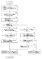
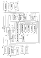
- FIG. 6 is a flowchart showing an example of the function setting processing operation performed by the gateway ECU 50 and the server device 2 in the security system 1 according to the embodiment (1).
- the gateway ECU 50 is configured to always operate regardless of the state of the vehicle 4, and this processing operation is repeatedly executed, for example, during the operation of the gateway ECU 50.
- step S1 the gateway ECU 50 operates as the state information acquisition unit 53, and the own vehicle (vehicle 4) is connected to the diagnostic device connection unit 41, the sensor group 42, or the ECU group via the gateway function unit 51.
- the process of acquiring the state information including the state is performed, and then the process proceeds to step S2.
- the state information to be acquired at least one of the states in which the own vehicle is parked, started, running or stopped, and under maintenance. Acquire dynamic information indicating. Further, as a second example of the state information to be acquired, the power information indicating the power state of the battery 47 of the own vehicle, for example, the remaining power amount of the battery 47, the setting state such as the eco mode, may be acquired.
- step S2 the gateway ECU 50 operates as the first determination unit 54a of the operation setting determination unit 54, and sets the operation settings of the security functions shared by the gateway ECU 50 and the server device 2 according to the state information acquired in step S1.
- the process of determining is performed, and the process proceeds to step S3.
- the acquired state information is the dynamic information of the vehicle 4 given in the first example
- the acquired dynamic information is collated with the security function setting table (see FIG. 3) read from the setting information storage unit 71. To do.
- the security function setting table the operation settings of each security function corresponding to the state of the own vehicle (either parked, started, running or stopped, or under maintenance) indicated by the acquired dynamic information. (Whether it should be set to be valid or invalid) is determined, and the process of reading the data of the determined operation setting (valid or invalid) is performed.
- the acquired state information is the electric power information of the vehicle 4 given in the second example above
- the acquired electric power information is collated with the security function setting table (see FIG. 4) read from the setting information storage unit 71.
- the security function setting table is set with the power status of the own vehicle indicated by the acquired power information (remaining power 30% or more, remaining power less than 30%, remaining power less than 10%, and remaining power 30% or more).
- the operation setting of each security function corresponding to any of the above) is determined, and the process of reading the data of the determined operation setting (valid or invalid) is performed.
- step S3 the gateway ECU 50 operates as the sharing notification unit 56, and based on the operation setting of the security function determined in step S2, the gateway ECU 50 issues a sharing notification for enabling or disabling each of the security functions of the server device 2. This is performed on the server device 2, and the process proceeds to step S4.
- step S4 the gateway ECU 50 sets a predetermined response waiting time and performs a process of waiting for a response from the server device 2.
- the server device 2 operates as the sharing notification acquisition unit 21 in step S11, performs a process of acquiring the sharing notification transmitted from the vehicle 4 in step S3, and when the sharing notification is acquired from the vehicle 4, the sharing notification is obtained in step S12. Proceed with processing.
- step S12 the server device 2 operates as the second setting unit 22, and based on the sharing notification acquired in step S11, a process of enabling or disabling each of the security functions of the server device 2 (function sharing setting process). Is performed, and the process proceeds to step S13.
- step S13 the server device 2 operates as the setting completion notification unit 23, performs a process of notifying the vehicle 4 of the completion of the setting when the sharing setting process of the security function in step S12 is completed, and then the server device 2 After finishing the processing in, the server device 2 executes the security function set to be valid.
- step S5 the gateway ECU 50 determines whether or not there is a response from the server device 2 within the response waiting time set in step S4, that is, whether or not the setting completion notification is obtained from the server device 2. If it is determined that there is a response (the setting completion notification has been obtained), the process proceeds to step S6.
- step S6 the gateway ECU 50 operates as the first setting unit 55, and a process of enabling or disabling each of the security functions of the gateway ECU 50 based on the operation setting of the security function determined in step S2 (function sharing setting). Processing) is performed, and then the process returns to step S1 and the processing is repeated.
- step S5 determines in step S5 that there is no response from the server device 2 within the response waiting time (has not acquired the setting completion notification)
- the gateway ECU 50 proceeds to step S7, and in step S7, The process of suspending the setting change of the security function is performed, and the process proceeds to step S8.
- step S8 the gateway ECU 50 determines whether or not the allocation notification to the server device 2 has been retried three or more times, and if it is determined that the retry is less than three times, the process returns to step S3 and the server device 2 is retried. Then, the sharing notification is sent again. On the other hand, if it is determined in step S8 that the number of retries is three or more, the process returns to step S1, the state information acquisition process is performed, and the process is repeated thereafter.
- the security system 1 as a whole can suppress the power consumption related to the security function in the vehicle 4 while maintaining the protection function of the in-vehicle system 40 by the security function. It is possible to maintain the protection function by the security function and suppress the power consumption related to the security function at the same time.
- the operation settings of the security functions shared by the gateway ECU 50 and the server device 2 are determined according to the acquired state information. Then, each security function of the gateway ECU 50 is enabled or disabled based on the determined operation setting. In addition, the server device 2 is notified of the division based on the determined operation settings.
- the security function of the gateway ECU 50 can be shared by the server device 2 according to the state information such as the dynamic information or the electric power information of the vehicle 4, and the security of the security system 1 as a whole is ensured. It is possible to suppress the power consumption related to the security function in the vehicle 4 while maintaining the security function for the vehicle 4.
- the security function setting table is stored in the setting information storage unit 71, and the operation setting determination unit 54 of the own vehicle indicated by the state information acquired from the security function setting table.
- Security function corresponding to the state By determining the operation setting of each, the state of the own vehicle includes various states (such as the dynamics or the power state of the vehicle 4), or the security function includes various functions. However, the processing load of the operation setting determination unit 54 can be reduced, and the processing performed by the operation setting determination unit 54 can be speeded up.
- the server device 2 can share the security function so that the protection function by the security function can be maintained or strengthened according to the dynamics of the own vehicle or the power state of the own vehicle.
- the security function unit 60 includes the in-vehicle communication encryption unit 61, the authentication unit 62, the access control unit 63, the intrusion detection unit 64, and the log recording unit 65, so that the vehicle can be in the state of the own vehicle. Accordingly, it is possible to more appropriately balance the maintenance of the protection function by the security function shared by the vehicle 4 and the server device 2 and the suppression of the power consumption related to the security function.
- the security functions of the server device 2 are set to be valid or invalid based on the sharing notification acquired from the vehicle 4, so that the server device 2 It is possible to switch the operation setting of the security function executed in the above based on the sharing notification. Therefore, by paying a part of the security function of the vehicle 4 according to the state of the vehicle 4, the security function of the vehicle 4 as a whole is maintained while maintaining the security function for ensuring the safety. The power consumption involved can be suppressed.
- FIG. 7 is a block diagram showing a functional configuration example of the in-vehicle system 40A on which the gateway ECU 50A according to the embodiment (2) is mounted.
- the same reference numerals are given to the configurations having the same functions as the gateway ECU 50 and the in-vehicle system 40 according to the embodiment (1), and the description thereof will be omitted.
- the main difference between the gateway ECU 50A according to the embodiment (2) and the gateway ECU 50 according to the embodiment (1) is that the operation setting determination unit 54 of the security control unit 52A has the first determination unit 54a. Instead, the second determination unit 54b is equipped, and the storage unit 70A is equipped with the allowable power consumption information storage unit 73 and the power consumption information storage unit 74 instead of the setting information storage unit 71. is there.
- the allowable power consumption information storage unit 73 stores an allowable power consumption table including the relationship between the state of one or more own vehicles and the allowable power consumption of the security function of the gateway ECU 50A.
- FIG. 8 is a diagram showing a data configuration example of the allowable power consumption table stored in the allowable power consumption information storage unit 73.
- the allowable power consumption table shown in FIG. 8 includes the relationship between one or more own vehicle states (vehicle states) and the allowable power consumption of the security function of the gateway ECU 50A, and further includes one or more own vehicle states and a server.
- the data configuration includes the relationship with the operation settings (valid or invalid settings) of each security function shared by the device 2 (cloud).
- the vehicle status item includes the status of the own vehicle corresponding to the status information acquired by the status information acquisition unit 53, which is parked, started, running, stopped, and under maintenance.
- the value of the allowable power consumption of the security function of the vehicle 4 in each vehicle state is registered.
- the value of the allowable power consumption shown in FIG. 8 is an example, and can be appropriately set depending on the battery capacity of the vehicle 4, the type of security function, and the number of mounted vehicles 4.
- the cloud security functions include intrusion detection and log recording, and settings for enabling or disabling these security functions are registered in each vehicle state.
- the security function of the cloud is not limited to these, and other functions may be added.
- the cloud if the vehicle state is parked, running, stopped, or under maintenance, the cloud enables intrusion detection and logging, and if the vehicle state is starting, the cloud is Settings for disabling intrusion detection and enabling logging are registered.
- the allowable power consumption table may not include the data of the operation settings of the cloud security function.
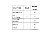
- the power consumption information storage unit 74 stores a power consumption table including the relationship between the power consumption and the priority of each security function of the gateway ECU 50A.
- FIG. 9 is a diagram showing a data configuration example of the power consumption table stored in the power consumption information storage unit 74.
- the power consumption table shown in FIG. 9 has a data structure including the relationship between the power consumption of each security function included in the security function unit 60 of the vehicle 4 and the priority.
- the value of power consumption for each security function is registered.
- the priority indicates, for example, the operation priority among the security functions included in the security function unit 60, and in the example shown in FIG. 9, the smaller the priority value, the higher the priority. There is. That is, the log recording has the highest priority with the priority "1", and the in-vehicle communication encryption has the lowest priority with the priority "5".
- the priority data is used when selecting a security function to enable or when selecting a security function to disable.
- the data of the permissible power consumption table stored in the permissible power consumption information storage unit 73 and the data of the power consumption table stored in the power consumption information storage unit 74 are read by the operation setting determination unit 54.
- the operation setting determination unit 54 includes the second determination unit 54b, and the second determination unit 54b includes the total power consumption of the security functions of the gateway ECU 50A for which the operation is effectively set, and the acquired state information. Based on the permissible power consumption of the security function in the state of the own vehicle indicated by, the process of determining the operation setting of each security function is performed.
- the second determination unit 54b reads the allowable power consumption table (FIG. 8) from the allowable power consumption information storage unit 73, and the state information acquired by the state information acquisition unit 53 from the allowable power consumption table. Acquires the allowable power consumption of the security function corresponding to the state of the own vehicle indicated by and the operation setting data of the security function of the cloud. For example, if the vehicle is parked, the allowable power consumption "100mW" and the operation setting of the cloud security function "Enable intrusion detection and enable log recording" are acquired from the allowable power consumption table. To do. Then, the second determination unit 54b sends the acquired operation setting of the security function of the cloud to the sharing notification unit 56.
- the allowable power consumption table FIG. 8
- the second determination unit 54b reads the power consumption table (FIG. 9) from the power consumption information storage unit 74, and is currently enabled from the power consumption table (all initial values are set to be valid). Data (priority, power consumption) of each security function is extracted and stored in the effective security function table area provided in the memory (for example, RAM of the security control unit 52A).
- the second determination unit 54b determines the allowable power consumption of the security function corresponding to the vehicle state and the power consumption of the security function (that is, the function whose operation is effectively set) stored in the effective security function table area. The process of determining the operation setting (whether to enable or disable) of each security function is performed by comparing with the total of.
- the second determination unit 54b has a lower priority among the security functions stored in the effective security function table area. It is possible to make a decision to disable a feature (in other words, remove it from the active security feature tablespace).
- the second determination unit 54b is not stored in the effective security function table area (in other words, its power consumption). It is possible to make a decision to enable (in other words, add to the effective security function tablespace) the function with high priority from the security functions (the operation is set to be disabled).
- the first setting unit 55 tells the security function unit 60 based on the operation setting (that is, the security function information stored in the effective security function table area) determined by the second determination unit 54b of the operation setting determination unit 54. Performs processing to enable or disable each of the included security functions. That is, the first setting unit 55 performs a process of effectively setting the security function stored in the effective security function table area.
- the sharing notification unit 56 gives the server device 2 a sharing notification for enabling or disabling each of the security functions of the server device 2 based on the operation settings of the cloud security function acquired from the second determination unit 54b. Do it against.
- the server device 2 acquires a sharing notification from the vehicle 4, and based on the acquired sharing notification, enables or disables each of the security functions of the server device 2. It is possible to perform the processing to be performed.
- FIG. 10 is a flowchart showing an example of the function setting processing operation performed by the security control unit 52A constituting the gateway ECU 50A according to the embodiment (2). This processing operation is executed in place of step S2 of the flowchart shown in FIG.
- step S21 the gateway ECU 50A reads the power consumption table (FIG. 9) of the security function from the power consumption information storage unit 74, and data (priority) of each security function currently enabled from the power consumption table. , Power consumption) is extracted and stored in the effective security function table area provided in the memory, and the process proceeds to step S22.
- the gateway ECU 50A reads the power consumption table (FIG. 9) of the security function from the power consumption information storage unit 74, and data (priority) of each security function currently enabled from the power consumption table. , Power consumption) is extracted and stored in the effective security function table area provided in the memory, and the process proceeds to step S22.
- all the security functions in the power consumption table may be regarded as effective, and the data of each security function may be stored in the effective security function table area.
- step S22 the gateway ECU 50A performs a process of calculating the total power consumption of each security function stored in the effective security function table, and proceeds to step S23.
- step S23 the gateway ECU 50A reads the allowable power consumption table from the allowable power consumption information storage unit 73, and corresponds to the state (vehicle state) of the own vehicle indicated by the acquired state information from the allowable power consumption table. The process of acquiring the allowable power consumption is performed, and the process proceeds to step S24.
- step S24 the gateway ECU 50A determines whether or not the total power consumption calculated in step S22 is equal to or greater than the allowable power consumption acquired in step S23, and if it is determined to be equal to or greater than the allowable power consumption, step S25. Proceed to processing.
- step S25 the gateway ECU 50A extracts the power consumption data of the security function (lowest priority function) having the lowest priority from the security functions stored in the effective security function table in step S21, and consumes the power consumption calculated in step S22.
- the process of subtracting the power consumption of the lowest priority function from the total power consumption to recalculate the total power consumption is performed, and the process proceeds to step S26.
- step S26 the gateway ECU 50A determines whether or not the total power consumption recalculated in step S25 is less than the allowable power consumption acquired in step S23, and if it is determined that the total power consumption is not less than the allowable power consumption, step S26. Return to S25 and repeat the process. On the other hand, if it is determined in step S26 that the power consumption is less than the allowable power consumption, the process proceeds to step S27.
- step S27 the gateway ECU 50A performs a process of deleting the security function having the lowest priority from the security functions stored in the effective security function table area in step S21 (deletion update process), and then proceeds to step S28. ..
- step S28 a process (determining the operation setting) for effectively determining the security function stored in the effective security function table area after the update (in this case, after the deletion and update) is performed, and then the step shown in FIG. 6 is performed. Proceed to S3.
- step S24 determines whether the total value of the power consumption calculated in step S22 is less than the allowable power consumption acquired in step S23. If it is determined in step S24 that the total value of the power consumption calculated in step S22 is less than the allowable power consumption acquired in step S23, the process proceeds to step S29.
- step S29 the gateway ECU 50A determines in step S21 whether or not there is an invalid security function that is not stored in the effective security function table area, and if it is determined that there is no invalid security function, the process is performed in step S33. To proceed. On the other hand, if it is determined that there is an invalid security function, the process proceeds to step S30.
- step S30 the gateway ECU 50A extracts the power consumption data of the security function (high priority function) having the highest priority from the invalid security functions that are not stored in the effective security function table area from the power consumption table. , The power consumption of the high priority function is added to the total power consumption calculated in step S22 to recalculate the total power consumption, and the process proceeds to step S31.
- the security function high priority function
- step S31 the gateway ECU 50A determines whether or not the total power consumption recalculated in step S30 is less than the allowable power consumption acquired in step S23, and if it is determined that the total power consumption is less than the allowable power consumption, step S31. The process proceeds to S32.
- step S32 the gateway ECU 50A adds a high-priority security function used for recalculating the total power consumption in step S30 to the security function stored in the effective security function table area in step S21 (additional update process). ), And then proceed to step S28.
- step S28 the gateway ECU 50A performs a process (determination of operation setting) for effectively determining the security function stored in the effective security function table area after the update (after the additional update), and then shows in FIG. The process proceeds to step S3.
- step S31 if the gateway ECU 50A determines that the total power consumption recalculated in step S30 is not less than the allowable power consumption, the process proceeds to step S33.
- step S33 the gateway ECU 50A performs a process (determination of operation setting) for effectively determining the security function stored in the effective security function table area in step S21, and then proceeds to step S3 shown in FIG. ..
- step S3 the server device 2 is notified of the division of duties for enabling or disabling each of the security functions of the server device 2 based on the operation settings of the cloud security function acquired from the allowable power consumption table. To do.
- the total power consumption is equal to or less than the allowable power consumption according to the allowable power consumption of the security function in the state of the own vehicle. It is possible to enable or disable each of the security functions and set them, so that the operation setting can be determined flexibly, and the power consumption related to the security function in the vehicle 4 can be appropriately suppressed. ..
- the second determination unit 54b compares the allowable power consumption acquired from the allowable power consumption table with the total power consumption of the security functions stored in the effective security function table area, and the security function is compared. Each operation setting (for example, whether to enable or disable) is determined. By using the permissible power consumption table and the power consumption table, it is possible to reduce the processing load of the second determination unit 54b and to speed up the processing performed by the second determination unit 54b.
- the security functions stored in the effective security function table area are included. Makes a decision to disable low priority features. As a result, it is possible to maintain the state in which the high-priority function is effectively set, and the security function can be switched and set so as not to exceed the allowable power consumption, and the allowable power consumption is taken into consideration and appropriate. Security functions can be set so as to consume power.
- the gateway ECU 50A when the total power consumption is less than the acquired allowable power consumption as a result of the comparison by the second determination unit 54b, the operation is set to be invalid from the security functions. A decision is made to enable the high priority features. As a result, when the allowable power consumption is less than the allowable power consumption, the security function can be switched and set so that the function having a high priority is effectively set, and the appropriate power consumption in consideration of the allowable power consumption is taken into consideration. The security function can be set so as to be.
- FIG. 11 is a block diagram showing a functional configuration example of the in-vehicle system 40B on which the gateway ECU 50B according to the embodiment (3) is mounted.
- the configurations having the same functions as the gateway ECU 50 and the in-vehicle system 40 according to the embodiment (1) and the gateway ECU 50A and the in-vehicle system 40A according to the embodiment (2) are designated by the same reference numerals and the description thereof will be described. It will be omitted.
- the main difference between the gateway ECU 50B according to the embodiment (3) and the gateway ECU 50 according to the embodiment (1) and the gateway ECU 50A according to the embodiment (2) is the operation setting of the security control unit 52B.
- the determination unit 54 is equipped with the first determination unit 54a and the second determination unit 54b, and the storage unit 70B includes the setting information storage unit 71, the allowable power consumption information storage unit 73, and the power consumption information storage unit 74. Is the point that is equipped.
- the gateway ECU 50B according to the embodiment (3) has a configuration of a characteristic portion of the gateway ECU 50 according to the embodiment (1) and the gateway ECU 50A according to the embodiment (2).
- the first determination unit 54a and the second determination unit 54b included in the operation setting determination unit 54 may be configured so that their operations can be switched according to predetermined conditions. For example, the user may be allowed to make a selection via the HMI device 46a.
- the first determination unit 54a and the second determination unit 54b may be switchable according to the state of the own vehicle. For example, when the vehicle state as the state of the own vehicle is parked or under maintenance, the operation of the security function is set using the security function setting table (FIG. 3) by the first determination unit 54a, and the vehicle is started or running. When the vehicle is in the middle or stopped, the operation of the security function may be set by using the allowable power consumption table and the power consumption table by the second determination unit 54b.
- the security function setting table FIG. 3
- the operation setting of the security function using the allowable power consumption table and the power consumption table is performed by the second determination unit 54b. If the remaining power is not sufficient, the operation of the security function may be set using the security function setting table (FIG. 4) by the first determination unit 54a.
- step S2 the gateway ECU 50B operates as the first determination unit 54a, and instead of steps S7 and S8, the processing of the flowchart shown in FIG. 10 (step S21). -Step S33) may be executed, that is, it may be configured to operate as the second determination unit 54b.
- the first determination unit 54a and the second determination unit 54b included in the operation setting determination unit 54 are configured so that their operations can be switched according to predetermined conditions. It is possible to increase the variation of the operation setting of the security function according to the state of the own vehicle and to perform the operation setting with high flexibility by operating the operation in combination or in combination. Therefore, it is possible to more appropriately achieve both the maintenance of the protection function by the security function and the reduction of the power consumption related to the security function.
- the security control units 52, 52A, 52B mounted on the gateway ECUs 50, 50A, 50B may be mounted on another ECU, or the security ECU equipped with the security control units 52, 52A, 52B may be mounted on an in-vehicle system. It may be configured to connect to 40 or the like.
- the moving body on which the security device according to the present invention is mounted is not limited to the vehicle 4 traveling on the road, and is, for example, an automatic guided vehicle (AGV) used as an industrial device in a factory or the like, or an automated guided vehicle. It may be an automatic guided vehicle or the like.
- AGV automatic guided vehicle
- the types of these unmanned vehicles (guidance method) are not particularly limited.
- the guidance system may be, for example, any of an autonomous guidance system, an image recognition system, an electromagnetic induction system, an optical guidance system, or an electromagnetic induction system.
- the security system including the unmanned transport vehicle equipped with the above-mentioned security device and the above-mentioned server device, the security system as a whole maintains the protection function by the security function in the unmanned transport vehicle. It is possible to construct an industrial equipment system capable of suppressing the power consumption related to the security function, maintaining the protection function by the security function, and suppressing the power consumption related to the security function at the same time.
- the present invention is widely used in the security-related industrial field such as an in-vehicle system, in which one or more devices detect an attack on a device system connected via a communication path and take countermeasures against the detected attack. It can be used.
- Embodiments of the present invention may also be described as, but are not limited to, the following appendices.
- Appendix 1 A security device (50) mounted on a mobile body (4) in a security system (1) including a server device (2) and a mobile body (4) capable of communicating with the server device (2).
- a state information acquisition unit (53) that acquires state information including the state of the self-moving body
- An operation setting determination unit (54) that determines the operation settings of each of the security functions shared by the security device (50) and the server device (2) according to the acquired state information.
- the first setting unit (55) that enables or disables each of the security functions of the security device (50)
- the sharing notification unit (56) that gives the sharing notification to the server device (2) to enable or disable each of the security functions of the server device (2).
- a security function setting method in a security system (1) including a server device (2) and a mobile body (4) capable of communicating with the server device (2).
- the security device (50) mounted on the mobile body (4)
- the state information acquisition step (S1) for acquiring the state information including the state of the self-moving body
- An operation setting determination step (S2) for determining the operation settings of each of the security functions shared by the security device (50) and the server device (2) according to the acquired state information.
- the server device (2) In the sharing notification acquisition step (S11) of acquiring the sharing notification from the moving body, A security function setting method including a second setting step (S12) for setting each of the security functions of the server device (2) to be valid or invalid based on the acquired notification of sharing.
- the state information acquisition step (S1) for acquiring the state information including the state of the self-moving body, and An operation setting determination step (S2) for determining the operation settings of the security functions shared by the computer (52) and the server device (2) according to the acquired state information.
- the first setting step (S6) for enabling or disabling each of the security functions of the computer (52) based on the determined operation setting, and Based on the determined operation setting, the sharing notification step (S3) of giving the sharing notification to the server device (2) for enabling or disabling each of the security functions of the server device (2) is performed.
- the state information acquisition step (S1) for acquiring the state information including the state of the self-moving body, and An operation setting determination step (S2) for determining the operation settings of the security functions shared by the computer (52) and the server device (2) according to the acquired state information.
- the first setting step (S6) for enabling or disabling each of the security functions of the computer (52) based on the determined operation setting, and Based on the determined operation setting, the sharing notification step (S3) of giving the sharing notification to the server device (2) for enabling or disabling each of the security functions of the server device (2) is performed.
- a computer-readable storage medium that stores a program to be executed.
- Security system 2 Server device 3 Communication network 4 Vehicle (mobile) 10 Communication unit 11 Control unit 12 Storage unit 13 Security countermeasure organization 21 Shared notification acquisition unit 22 Second setting unit 23 Setting completion notification unit 24 Countermeasure command unit 25 Security function unit 26 Intrusion detection unit 27 Log recording unit 40, 40A, 40B In-vehicle System 41 Diagnostic machine connection 42 Sensor group 43 Driving system ECU group 43a Power monitoring unit 44 Operation support system ECU group 45 Body system ECU group 46 Information system ECU group 46a HMI device 46b Communication unit 47 Battery 50, 50A, 50B Gateway ECU ( Security device) 51 Gateway function unit 52, 52A, 52B Security control unit 53 Status information acquisition unit 54 Operation setting determination unit 54a First determination unit 54b Second determination unit 55 First setting unit 56 Shared notification unit 60 Security function unit 61 In-vehicle communication encryption unit (Internal communication encryption section) 62 Authentication unit 63 Access control unit 64 Intrusion detection unit 65 Log recording unit 70, 70A, 70B Storage unit 71 Setting information storage unit 72 Log data storage unit 73 Allowable power consumption information storage unit
Landscapes
- Engineering & Computer Science (AREA)
- Computer Security & Cryptography (AREA)
- Software Systems (AREA)
- Theoretical Computer Science (AREA)
- Mechanical Engineering (AREA)
- Computer Hardware Design (AREA)
- Physics & Mathematics (AREA)
- General Engineering & Computer Science (AREA)
- General Physics & Mathematics (AREA)
- Computer Networks & Wireless Communication (AREA)
- Signal Processing (AREA)
- Small-Scale Networks (AREA)
Abstract
L'objectif de la présente invention est de fournir un dispositif de sécurité qui permet de supprimer une consommation d'énergie tout en maintenant une fonction de sécurité. Le dispositif de sécurité est monté sur un corps mobile dans un système de sécurité qui comprend un dispositif serveur et le corps mobile, le dispositif de sécurité comprenant : une unité de détermination de réglage de fonctionnement qui détermine, en fonction d'informations d'état comprenant l'état d'un corps mobile autonome, des réglages de fonctionnement pour chaque fonction de sécurité attribuée dans le dispositif de sécurité et le dispositif serveur ; une première unité de réglage qui règle, sur la base des réglages de fonctionnement déterminés, chaque fonction de sécurité du dispositif de sécurité comme étant activée ou désactivée ; et une unité de notification d'attribution qui envoie au dispositif serveur, sur la base des paramètres de fonctionnement déterminés, une notification d'attribution pour régler chacune des fonctions de sécurité du dispositif serveur comme étant activée ou désactivée.
Priority Applications (1)
| Application Number | Priority Date | Filing Date | Title |
|---|---|---|---|
| PCT/JP2019/029628 WO2021019637A1 (fr) | 2019-07-29 | 2019-07-29 | Dispositif de sécurité, dispositif serveur, système de sécurité et procédé de réglage de fonction de sécurité |
Applications Claiming Priority (1)
| Application Number | Priority Date | Filing Date | Title |
|---|---|---|---|
| PCT/JP2019/029628 WO2021019637A1 (fr) | 2019-07-29 | 2019-07-29 | Dispositif de sécurité, dispositif serveur, système de sécurité et procédé de réglage de fonction de sécurité |
Publications (1)
| Publication Number | Publication Date |
|---|---|
| WO2021019637A1 true WO2021019637A1 (fr) | 2021-02-04 |
Family
ID=74228598
Family Applications (1)
| Application Number | Title | Priority Date | Filing Date |
|---|---|---|---|
| PCT/JP2019/029628 Ceased WO2021019637A1 (fr) | 2019-07-29 | 2019-07-29 | Dispositif de sécurité, dispositif serveur, système de sécurité et procédé de réglage de fonction de sécurité |
Country Status (1)
| Country | Link |
|---|---|
| WO (1) | WO2021019637A1 (fr) |
Cited By (1)
| Publication number | Priority date | Publication date | Assignee | Title |
|---|---|---|---|---|
| JPWO2022004544A1 (fr) * | 2020-06-30 | 2022-01-06 |
Citations (3)
| Publication number | Priority date | Publication date | Assignee | Title |
|---|---|---|---|---|
| US20060200542A1 (en) * | 2005-02-28 | 2006-09-07 | Tendril Networks, Inc. | Apparatus and method for network-aware power management |
| WO2016140198A1 (fr) * | 2015-03-04 | 2016-09-09 | 日本電信電話株式会社 | Dispositif de prévention d'invalidation de mesure de sécurité, procédé de prévention d'invalidation de mesure de sécurité et programme de prévention d'invalidation de mesure de sécurité |
| WO2018186053A1 (fr) * | 2017-04-07 | 2018-10-11 | パナソニック インテレクチュアル プロパティ コーポレーション オブ アメリカ | Procédé de détection de communication non autorisée, système de détection de communication non autorisée, et programme associé |
-
2019
- 2019-07-29 WO PCT/JP2019/029628 patent/WO2021019637A1/fr not_active Ceased
Patent Citations (3)
| Publication number | Priority date | Publication date | Assignee | Title |
|---|---|---|---|---|
| US20060200542A1 (en) * | 2005-02-28 | 2006-09-07 | Tendril Networks, Inc. | Apparatus and method for network-aware power management |
| WO2016140198A1 (fr) * | 2015-03-04 | 2016-09-09 | 日本電信電話株式会社 | Dispositif de prévention d'invalidation de mesure de sécurité, procédé de prévention d'invalidation de mesure de sécurité et programme de prévention d'invalidation de mesure de sécurité |
| WO2018186053A1 (fr) * | 2017-04-07 | 2018-10-11 | パナソニック インテレクチュアル プロパティ コーポレーション オブ アメリカ | Procédé de détection de communication non autorisée, système de détection de communication non autorisée, et programme associé |
Cited By (4)
| Publication number | Priority date | Publication date | Assignee | Title |
|---|---|---|---|---|
| JPWO2022004544A1 (fr) * | 2020-06-30 | 2022-01-06 | ||
| WO2022004544A1 (fr) * | 2020-06-30 | 2022-01-06 | ファナック株式会社 | Dispositif de commande |
| JP7392152B2 (ja) | 2020-06-30 | 2023-12-05 | ファナック株式会社 | 制御装置 |
| US12368594B2 (en) | 2020-06-30 | 2025-07-22 | Fanuc Corporation | Control device |
Similar Documents
| Publication | Publication Date | Title |
|---|---|---|
| US11938898B2 (en) | Vehicle control system | |
| KR20190127841A (ko) | 차량용 지능형 무선 액세스 시스템 및 방법 | |
| JP7067509B2 (ja) | 自動バレーパーキングシステム、自動バレーパーキングプログラムおよび記憶媒体 | |
| US11367356B1 (en) | Autonomous fleet service management | |
| JP7318710B2 (ja) | セキュリティ装置、インシデント対応処理方法、プログラム、及び記憶媒体 | |
| US20210067513A1 (en) | Distributed vehicle network access authorization | |
| EP3793168A1 (fr) | Dispositif et procédé de délégation d'autorité de conduite de véhicule | |
| CN113678408A (zh) | 汽车用运算系统和接收数据的处理方法 | |
| US12197210B2 (en) | Server, information processing system and information processing method | |
| US12147798B2 (en) | Server managing operation of automatic driving vehicle and updating of control program, and information processing method | |
| JP7160206B2 (ja) | セキュリティ装置、攻撃対応処理方法、コンピュータプログラム、及び記憶媒体 | |
| WO2021019637A1 (fr) | Dispositif de sécurité, dispositif serveur, système de sécurité et procédé de réglage de fonction de sécurité | |
| EP3951671B1 (fr) | Autorisation de service de véhicule | |
| US20240427927A1 (en) | Vehicle-related sensitive data determination and removal | |
| US12174927B2 (en) | Blockchain method and system to prevent camera spoofing before operating vehicle | |
| US20240163277A1 (en) | Secure service operation authorization | |
| US11176763B2 (en) | Electronic key system and electronic key managing apparatus | |
| JP7259966B2 (ja) | セキュリティ装置、設定変更方法、プログラム、及び記憶媒体 | |
| US20250220429A1 (en) | Access control device and access control method | |
| US20250300815A1 (en) | Security key distribution | |
| US12511959B2 (en) | Authentication system and authentication method | |
| US20240394396A1 (en) | Authentication system and relay device | |
| CN116788200B (zh) | 车辆控制的方法、装置以及存储介质 | |
| CN113002479B (zh) | 用于机动车的盗窃警报 | |
| US20260006029A1 (en) | Management of vehicle network access |
Legal Events
| Date | Code | Title | Description |
|---|---|---|---|
| 121 | Ep: the epo has been informed by wipo that ep was designated in this application |
Ref document number: 19939616 Country of ref document: EP Kind code of ref document: A1 |
|
| NENP | Non-entry into the national phase |
Ref country code: DE |
|
| 122 | Ep: pct application non-entry in european phase |
Ref document number: 19939616 Country of ref document: EP Kind code of ref document: A1 |
|
| NENP | Non-entry into the national phase |
Ref country code: JP |