WO2021019710A1 - プロペラファンの羽根車、送風機、および空気調和機の室外機 - Google Patents
プロペラファンの羽根車、送風機、および空気調和機の室外機 Download PDFInfo
- Publication number
- WO2021019710A1 WO2021019710A1 PCT/JP2019/029948 JP2019029948W WO2021019710A1 WO 2021019710 A1 WO2021019710 A1 WO 2021019710A1 JP 2019029948 W JP2019029948 W JP 2019029948W WO 2021019710 A1 WO2021019710 A1 WO 2021019710A1
- Authority
- WO
- WIPO (PCT)
- Prior art keywords
- propeller fan
- erection wall
- impeller
- suction
- suction side
- Prior art date
- Legal status (The legal status is an assumption and is not a legal conclusion. Google has not performed a legal analysis and makes no representation as to the accuracy of the status listed.)
- Ceased
Links
Images


Classifications
-
- F—MECHANICAL ENGINEERING; LIGHTING; HEATING; WEAPONS; BLASTING
- F04—POSITIVE - DISPLACEMENT MACHINES FOR LIQUIDS; PUMPS FOR LIQUIDS OR ELASTIC FLUIDS
- F04D—NON-POSITIVE-DISPLACEMENT PUMPS
- F04D29/00—Details, component parts, or accessories
- F04D29/26—Rotors specially for elastic fluids
- F04D29/32—Rotors specially for elastic fluids for axial flow pumps
- F04D29/325—Rotors specially for elastic fluids for axial flow pumps for axial flow fans
- F04D29/329—Details of the hub
-
- F—MECHANICAL ENGINEERING; LIGHTING; HEATING; WEAPONS; BLASTING
- F04—POSITIVE - DISPLACEMENT MACHINES FOR LIQUIDS; PUMPS FOR LIQUIDS OR ELASTIC FLUIDS
- F04D—NON-POSITIVE-DISPLACEMENT PUMPS
- F04D25/00—Pumping installations or systems
- F04D25/02—Units comprising pumps and their driving means
- F04D25/06—Units comprising pumps and their driving means the pump being electrically driven
-
- F—MECHANICAL ENGINEERING; LIGHTING; HEATING; WEAPONS; BLASTING
- F24—HEATING; RANGES; VENTILATING
- F24F—AIR-CONDITIONING; AIR-HUMIDIFICATION; VENTILATION; USE OF AIR CURRENTS FOR SCREENING
- F24F1/00—Room units for air-conditioning, e.g. separate or self-contained units or units receiving primary air from a central station
- F24F1/06—Separate outdoor units, e.g. outdoor unit to be linked to a separate room comprising a compressor and a heat exchanger
- F24F1/38—Fan details of outdoor units, e.g. bell-mouth shaped inlets or fan mountings
-
- F—MECHANICAL ENGINEERING; LIGHTING; HEATING; WEAPONS; BLASTING
- F05—INDEXING SCHEMES RELATING TO ENGINES OR PUMPS IN VARIOUS SUBCLASSES OF CLASSES F01-F04
- F05D—INDEXING SCHEME FOR ASPECTS RELATING TO NON-POSITIVE-DISPLACEMENT MACHINES OR ENGINES, GAS-TURBINES OR JET-PROPULSION PLANTS
- F05D2240/00—Components
- F05D2240/20—Rotors
- F05D2240/30—Characteristics of rotor blades, i.e. of any element transforming dynamic fluid energy to or from rotational energy and being attached to a rotor
- F05D2240/303—Characteristics of rotor blades, i.e. of any element transforming dynamic fluid energy to or from rotational energy and being attached to a rotor related to the leading edge of a rotor blade
-
- F—MECHANICAL ENGINEERING; LIGHTING; HEATING; WEAPONS; BLASTING
- F05—INDEXING SCHEMES RELATING TO ENGINES OR PUMPS IN VARIOUS SUBCLASSES OF CLASSES F01-F04
- F05D—INDEXING SCHEME FOR ASPECTS RELATING TO NON-POSITIVE-DISPLACEMENT MACHINES OR ENGINES, GAS-TURBINES OR JET-PROPULSION PLANTS
- F05D2250/00—Geometry
- F05D2250/70—Shape
- F05D2250/71—Shape curved
- F05D2250/712—Shape curved concave
-
- F—MECHANICAL ENGINEERING; LIGHTING; HEATING; WEAPONS; BLASTING
- F05—INDEXING SCHEMES RELATING TO ENGINES OR PUMPS IN VARIOUS SUBCLASSES OF CLASSES F01-F04
- F05D—INDEXING SCHEME FOR ASPECTS RELATING TO NON-POSITIVE-DISPLACEMENT MACHINES OR ENGINES, GAS-TURBINES OR JET-PROPULSION PLANTS
- F05D2270/00—Control
- F05D2270/01—Purpose of the control system
- F05D2270/11—Purpose of the control system to prolong engine life
- F05D2270/114—Purpose of the control system to prolong engine life by limiting mechanical stresses
Definitions
- An embodiment of the present invention relates to an impeller of a propeller fan, a blower, and an outdoor unit of an air conditioner.
- a propeller fan is used as a blower for the outdoor unit of the air conditioner.
- the propeller fan includes an impeller and an electric motor that generates a rotational driving force for the impeller.
- the impeller includes a tubular boss portion and a plurality of blade portions that project radially from the outer peripheral surface of the boss portion.
- the boss portion is a shaft mounting portion provided with a rotating shaft connecting the electric motor and the propeller fan, a plurality of ribs extending radially from the outer peripheral surface of the shaft mounting portion to the inner wall of the boss portion, and a downstream side connecting the plurality of ribs. It includes an erection wall portion and an upstream erection wall portion that connects a plurality of ribs on the upstream side of the downstream erection wall portion.
- the downstream erection wall and the upstream erection wall do not overlap in the direction along the rotation center line of the propeller fan.
- the upstream side erection wall portion is provided on the axial side of the base end portion of the front edge of the blade portion.
- an object of the present invention is to provide an impeller of a propeller fan capable of more effectively relieving stress concentration at the connection portion between the root portion of the front edge of the blade portion and the boss portion.
- the impeller of the propeller fan includes a boss portion and a plurality of blade portions that project radially from the outer peripheral surface of the boss portion, and the boss portion has the outer peripheral surface. It has a tubular portion extending from the suction side end to the blowout side end, a surface facing the direction along the center line of the tubular portion, and has a connecting portion continuous with the suction side end and extends inward of the tubular portion.
- a plurality of suction-side erection wall portions a plurality of surfaces facing the direction along the center line of the cylinder portion, closer to the blow-out side end than the suction-side erection wall portion, and extending inward of the cylinder portion.
- a blowout side erection wall portion is provided, and the root portion of the front edge of each of the blade portions is continuous with the suction side end.
- blower according to the embodiment of the present invention includes the propeller fan and an electric motor for driving the propeller fan.
- the outdoor unit of the air conditioner includes the blower and a heat exchanger that exchanges heat with the air flowing by the blower.
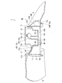
- the vertical sectional view of the second example of the impeller of the propeller fan which concerns on embodiment of this invention.
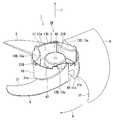
- FIG. 1 A perspective view of a third example of an impeller of a propeller fan according to an embodiment of the present invention as viewed from the outlet side.
- FIGS. 1 to 11 An embodiment of an impeller of a propeller fan, a blower, and an outdoor unit of an air conditioner according to the present invention will be described with reference to FIGS. 1 to 11.
- the same or corresponding configurations are designated by the same reference numerals.
- FIG. 1 is a cross-sectional view of an outdoor unit of an air conditioner according to an embodiment of the present invention.
- the air conditioner includes an outdoor unit 100 and an indoor unit (not shown).
- the outdoor unit 100 includes a housing 101, a blower 103 including an electric motor 102 inside the housing 101, a heat exchanger 105, a compressor 106, a four-way valve (not shown), and a controller (not shown). , Is equipped.
- the housing 101 includes a side plate 111 that covers the side surface, a top plate 112 that covers the ceiling, and a bottom plate 113 that covers the bottom surface.
- a partition plate 115 is provided inside the housing 101. The partition plate 115 divides the inside of the housing 101 into a machine room 117 and a heat exchange room 118.
- the side plate 111 has a plurality of suction holes 111a for sucking outside air into the outdoor unit 100.
- an outlet hole 112a and a bell mouth (not shown) for exhausting the outside air sucked into the outdoor unit 100 from the suction hole 111a of the side plate 111 to the outside of the outdoor unit 100 are provided. ..
- the compressor 106 is installed on the bottom plate 113 of the machine room 117. Further, the compressor 106 is arranged below the heat exchanger 105.
- the heat exchanger 105 is installed in the central part of the heat exchange chamber 118.
- the blower 103 is located above the heat exchanger 105 and is installed near the exhaust hole 111a of the top plate 112.
- the outdoor unit 100 is connected to the indoor unit via a refrigerant pipe (not shown).
- the compressor 106 is driven when the refrigeration cycle operation is started.
- the compressor 106 circulates the refrigerant through the refrigerant pipe and guides the refrigerant to the heat exchanger 105.
- the operation of the blower 103 is started.
- the electric motor 102 rotationally drives the propeller fan 1.
- the outside air is guided to the heat exchange chamber 118 from the suction hole 111a on the side surface of the housing 101, passes through the heat exchanger 105, and exchanges heat with the refrigerant in the heat exchanger 105.
- the air heat-exchanged by the heat exchanger 105 is guided by the bell mouth via the blower 103, and is discharged to the outside of the outdoor unit 100 from the blowout hole 112a above the housing 100.
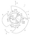
- FIG. 2 is a perspective view of the impeller of the propeller fan according to the embodiment of the present invention as viewed from the suction side.
- FIG. 3 is a perspective view of the impeller of the propeller fan according to the embodiment of the present invention as viewed from the outlet side.
- the propeller fan 1 As shown in FIGS. 2 and 3, the propeller fan 1 according to the present embodiment rotates in the rotation direction R indicated by the solid arrow in FIGS. 2 and 3, and the flow indicated by the solid arrow in FIGS. 2 and 3. Fluid, exclusively air, flows in the direction F.
- the propeller fan 1 is applied to, for example, an outdoor unit of an air conditioner, and is used for blowing air to an outdoor heat exchanger.
- the propeller fan 1 is a so-called axial fan.
- the propeller fan 1 includes an impeller 2 and an electric motor (not shown) for rotationally driving the impeller 2.
- the electric motor is equipped with an output shaft (not shown) that transmits rotational driving force to the impeller 2.
- the output shaft is the center of rotation of the impeller 2.
- FIG. 4 is a vertical sectional view of an impeller of a propeller fan according to an embodiment of the present invention.
- the impeller 2 of the propeller fan 1 is a so-called axial flow impeller.
- the impeller 2 is also simply called a propeller.
- the impeller 2 includes a boss portion 5 and a plurality of blade portions 6 that project radially from the outer peripheral surface 5a of the boss portion 5.
- the impeller 2 is integrally molded with, for example, resin.
- the plurality of blade portions 6 are arranged at equal intervals along the outer peripheral surface 5a of the boss portion 5 in the circumferential direction of the impeller 2, that is, in the rotation direction R of the propeller fan 1.
- the impeller 2 includes, for example, three blade portions 6. In this case, the three blades 6 are arranged at every 120 degree central angle.
- Each of the blade portions 6 is inclined toward the suction side in the rotation direction of the propeller fan 1 and is arranged on the outer peripheral surface 5a of the boss portion 5.
- the root portion 31a of the front edge portion 31 of the blade portion 6 coincides with the suction side end 11s of the boss portion 5.
- the boss portion 5 has a tubular portion 11 having an outer peripheral surface 5a of the boss portion 5 and extending from the suction side end 11s to the blowout side end 11b, and a suction side end surface 12a facing the direction along the center line of the tubular portion 11.
- a plurality of suction-side erection wall portions 12 having a connecting portion 12b continuous with the suction-side end 11s of the boss portion 5 and extending toward the center of the cylinder portion 11 and facing the direction along the center line of the cylinder portion 11.
- a plurality of blow-out side erection wall portions 13 having a blow-out side end surface 13a and closer to the blow-out side end 11b than the suction-side erection wall portion 12 and extending toward the center of the tubular portion 11, and a plurality of suction-side erection wall portions.
- a rotating shaft mounting portion 15 provided at the center of the tubular portion 11 via the 12 and a plurality of blowing-side erection wall portions 13 is provided.
- the rotating shaft mounting portion 15 is arranged on the rotating center line of the boss portion 5 and on the rotating center line of the impeller 2.
- a rotating shaft is fixed to the rotating shaft mounting portion 15.
- the impeller 2 is connected to the electric motor via a rotating shaft mounting portion 15 fixed to the rotating shaft.
- the rotary shaft mounting portion 15 may be one that fixes the inserted rotary shaft, or may be one that is integrated with the rotary shaft by insert molding.
- the plurality of suction-side erection wall portions 12 are flat plate portions having a substantially uniform thickness extending from the suction-side end 11s of the cylinder portion 11 toward the center of the cylinder portion 11.
- Each suction-side erection wall portion 12 has a front end 16 located forward in the rotation direction R of the propeller fan 1 and a rear end 17 located behind the front end 16. The outer edge of each suction-side erection wall portion 12 is continuously connected to the suction-side end 11s of the tubular portion 11.
- the plurality of blow-out side erection wall portions 13 are flat plate portions having a substantially uniform thickness extending from the blow-out side end 11b of the cylinder portion 11 toward the center of the cylinder portion 11.
- Each of the blowout side erection wall portions 13 has a front end 18 located forward in the rotation direction R of the propeller fan 1 and a rear end 19 located behind the front end 18.
- the outer edge of each of the blow-out side erection wall portions 13 is continuous with the blow-out side end 11b of the tubular portion 11.
- the outer edge of the blowout side erection wall portion 13 may be located inside the tubular portion 11 and may not be continuous with the blowout side end 11b.
- the plurality of suction side erection wall portions 12 and the plurality of outlet side erection wall portions 13 are alternately arranged in the rotation direction R of the propeller fan 1.
- the plurality of suction-side erection wall portions 12 and the plurality of outlet-side erection wall portions 13 do not overlap in the direction along the rotation center line of the propeller fan 1.
- the same number of suction-side erection wall portions 12, blow-out side erection wall portions 13, and blade portions 6 are provided.
- the suction side erection wall portion 12, the blowout side erection wall portion 13, and the blade portion 6 are regularly arranged around the rotation center of the propeller fan 1.
- suction side erection wall portion 12 the blowout side erection wall portion 13, and the blade portion 6 are provided by three as in the present embodiment
- a plurality of suction side erection wall portions 12 and a plurality of blowouts are provided.
- the positional relationship and the dimensional relationship between the side erection wall portion 13 and the plurality of blade portions 6 are the same every 120 degrees around the rotation center of the propeller fan 1.
- a vertical wall portion 21 extending in the direction of the rotation center line of the propeller fan 1 is provided between the suction side erection wall portion 12 and the blowout side erection wall portion 13 adjacent to each other in the direction of the rotation center line of the propeller fan 1.
- the longitudinal wall portion 21 has a substantially uniform thickness.
- Half of the vertical wall portions 21 are composed of the rear end 17 of each suction side erection wall portion 12 and the front edge 18 of each outlet side erection wall portion 13, and the other vertical wall portions 21 are each It is composed of a front end 16 of a suction side erection wall portion 12 and a trailing edge 19 of each outlet side erection wall portion 13.
- the vertical wall portion 21 is bridged between the inner peripheral surface 11a of the tubular portion 11 and the rotating shaft mounting portion 15.
- the plurality of vertical wall portions 21 extend radially from the rotating shaft mounting portion 15 to the tubular portion 11.
- the suction side erection wall portion 12 extends over the suction side end 21s of the adjacent vertical wall portions 21, the suction side end 11s of the tubular portion 11, and the suction side end 15s of the rotary shaft mounting portion 15, and is mounted on the rotary shaft. It spreads in a fan shape from the portion 15 toward the suction side end 11s of the tubular portion 11.
- the rotating shaft mounting portion 15 is a key point of the fan-shaped suction side erection wall portion 12.
- the blow-out side erection wall portion 13 extends over the blow-out side end 21b of the adjacent vertical wall portions 21, the blow-out side end 11b of the tubular portion 11, and the blow-out side end 15b of the rotary shaft mounting portion 15, and the rotary shaft mounting portion 15 It extends in a fan shape from the outlet side end 15b toward the outlet side erection wall portion of the tubular portion 11.
- the rotating shaft mounting portion 15 is a key point of the fan-shaped blowing-side erection wall portion 13. That is, the plurality of suction side erection wall portions 12 and the plurality of outlet side erection wall portions 13 are alternately and radially arranged around the rotating shaft mounting portion 15.
- the rear end 17 of the connecting portion 12b of the suction side erection wall portion 12 is located behind the root portion 31a of the front edge 31 of the nearest blade portion 6 in the rotation direction of the propeller fan 1.
- the rear end 17 of the suction side erection wall portion 12 is located behind the root portion 31a of the front edge 31 of the nearest blade portion 6.
- the front end 16 of the connecting portion 12b of the suction side erection wall portion 12 may coincide with the root portion 31a of the front edge 31 of the nearest blade portion 6 in the rotation direction of the propeller fan 1, or may coincide with the root portion 31a of the closest blade portion 6. It may be located behind the root portion 31a of the front edge 31, or may be located before the root portion 31a of the front edge 31 of the nearest blade portion 6. In FIG. 2, the front end 16 of the suction side erection wall portion 12 is located in front of the root portion 31a of the front edge 31 of the nearest blade portion 6.
- the root portion 31a of the front edge 31 of the blade portion 6 is sandwiched between the front end 16 and the rear end 17 of the connecting portion 12b of the suction side erection wall portion 12.
- the front end 16 and the rear end 17 of the suction side erection wall portion 12 sandwich the root portion 31a of the front edge 31 of the blade portion 6.
- the root portion 31a of the front edge 31 of each blade portion 6 is continuous with the suction side end 11s of the tubular portion 11. That is, the root portion 31a of the front edge 31 of the blade portion 6 and the outermost edge of the suction side erection wall portion 12 sandwich the suction side end 11s of the cylinder portion 11 between them without being offset in the rotation direction of the propeller fan 1. Facing at.
- the impeller 2 is continuous with the root portion 31a of the front edge 31 of the blade portion 6 continuous with the suction side end 11s of the tubular portion 11 and the suction side end 11s of the tubular portion 11. It is provided with a suction side erection wall portion 12. Therefore, the impeller 2 distributes the load generated at the root portion 31a of the front edge 31 of the blade portion 6 to the cylinder portion 11 of the boss portion 5, the suction side erection wall portion 12, and the longitudinal wall portion 21 to distribute the blades. The stress concentration at the root portion 31a of the front edge 31 of the portion 6 is relaxed.
- the suction side end 11s of the tubular portion 11 is not between the root portion 31a of the front edge 31 of the blade portion 6 and the outermost edge of the suction side erection wall portion 12, but protrudes toward the suction side of the propeller fan 1 to provide blades.
- the ratio of the load dispersed by the suction side erection wall portion 12 decreases. .. That is, the improvement of the stress concentration at the root portion 31a of the front edge 31 of the blade portion 6 remains insufficient.
- the rear end 17 of the suction side erection wall portion 12 is located in front of the root portion 31a of the front edge 31 of the blade portion 6 closest to the suction side erection wall portion 12, and the front edge 31 of the blade portion 6 is located.
- the suction side erection wall When the front end 16 of the portion 12 is located behind the root portion 31a of the front edge 31 of the blade portion 6 closest to the blade portion 6, the suction side erection wall portion 12 is generated at the root portion 31a of the front edge 31 of the blade portion 6.
- the load to be applied is applied as intended to relax the stress concentration at the root portion 31a of the front edge 31 of the blade portion 6.
- the rear end 17 of the suction side erection wall portion 12 is located behind the root portion 31a of the front edge 31 of the nearest blade portion 6 in the rotation direction R of the propeller fan 1. doing. Therefore, the impeller 2 distributes the load generated at the root portion 31a of the front edge 31 of the blade portion 6 to the cylinder portion 11 of the boss portion 5 and the suction side erection wall portion 12, and the front edge 31 of the blade portion 6 The stress concentration at the root portion 31a is relaxed.
- the impeller 2 according to the present embodiment includes a root portion 31a of the front edge 31 of the blade portion 6 sandwiched between the front end 16 and the rear end 17 of the suction side erection wall portion 12. Therefore, the impeller 2 distributes the load generated at the root portion 31a of the front edge 31 of the blade portion 6 to the cylinder portion 11 of the boss portion 5 and the suction side erection wall portion 12, and the front edge 31 of the blade portion 6 The stress concentration at the root portion 31a is more effectively relaxed.
- the impeller 2 according to the present embodiment includes a suction side erection wall portion 12 and a blowout side erection wall portion 13 that do not overlap in the direction along the rotation center line of the propeller fan 1. Therefore, the impeller 2 can be easily integrally molded by a mold that can be divided in the direction of the rotation center line.
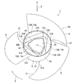
- FIG. 5 is a perspective view of a second example of the impeller of the propeller fan according to the embodiment of the present invention as viewed from the suction side.
- FIG. 6 is a perspective view of a second example of an impeller of a propeller fan according to an embodiment of the present invention as viewed from the outlet side.
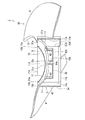
- FIG. 7 is a vertical sectional view of a second example of an impeller of a propeller fan according to an embodiment of the present invention.
- the impeller 2A (hereinafter, simply referred to as “impeller 2A”) of the second example of the propeller fan 1 according to the present embodiment is from the inner peripheral surface 11a of the tubular portion 11. It is provided with a plurality of suction-side erection wall portions 12A which are arranged at distant places and have an annularly continuous connecting portion 12b and are integrated by the annular portion 41.
- the suction side erection wall portion 12A is a plate portion having a substantially uniform thickness curved in a concave shape from the suction side end 11s of the tubular portion 11 toward the blowout side.
- the concave bottom that is, the portion of the suction-side erection wall portion 12A farthest from the suction-side end 11s of the tubular portion 11, is closest to the center of the propeller fan 1.
- the annular portion 41 integrates a plurality of suction-side erection wall portions 12A.
- the annular portion 41 is a part of the suction side erection wall portion 12A, and is curved in a concave shape from the suction side end 11s of the tubular portion 11 toward the blowout side.
- the portion of the plurality of suction side erection wall portions 12A near the cylinder portion 11 is connected to the cylinder portion 11 for each blade portion 6, while the portion of the plurality of suction side erection wall portions 12A far from the cylinder portion 11, in other words.
- the portions of the plurality of suction-side erection wall portions 12A near the rotating shaft mounting portion 15A are continuously connected by the annular portion 41. That is, the plurality of suction-side erection wall portions 12A are arranged radially from the annular portion 41 arranged inside the tubular portion 11 toward the inner peripheral surface 11a of the tubular portion 11.
- the front end 16 of the connection portion 12b of the suction side erection wall portion 12A is continuous with the rear end 17 of the connection portion 12b of the suction side erection wall portion 12A located forward in the rotation direction of the propeller fan 1.
- the front end 16 and the rear end 17 of the adjacent suction side erection wall portions 12A are continuously connected.
- the front end 16 and the rear end 17 of the continuous suction side erection wall portion 12A have a linear shape when viewed in the direction of the rotation center line of the propeller fan 1, and from the suction side end 11s of the tubular portion 11 to the blowout side. It has an arc shape that is recessed toward it.
- the longitudinal wall portion 21A extends in a flat plate shape in the direction of the rotation center line of the propeller fan 1 following the continuous front end 16 and rear end 17.
- the portion of the tubular portion 11 facing the vertical wall portion 21A in other words, the portion of the tubular portion 11 facing the vertical wall portion 21A is notched within a range that does not interfere with the support of the blade portion 6. It may be done. The weight of the propeller fan 1 can be reduced by this notch.
- the outlet side erection wall portion 13A is provided at a portion surrounded by the suction side erection wall portion 12A and the cylinder portion 11 when viewed in the direction of the rotation center line of the propeller fan 1.
- annular longitudinal wall portion 42 is provided on the inner edge of the annular portion 41.
- the annular longitudinal wall portion 42 extends from the inner edge of the annular portion 41 toward the outlet side end 11b of the tubular portion 11.
- the annular longitudinal wall portion 42 may or may not reach the outlet side end 11b of the tubular portion 11.
- the outlet side end 42b of the annular longitudinal wall portion 42 is connected to the rotating shaft mounting portion 15A.
- the inner edge shape of the annular portion 41 may be a simple circular shape when viewed in the direction of the rotation center line of the propeller fan 1, or may be a polygonal shape as shown in FIG.
- the polygonal inner edge shape includes, for example, a vertex arranged on a line segment that bisects the connection portion between the suction side erection wall portion 12A and the cylinder portion 11 in the rotation direction of the propeller fan 1, and the suction side erection wall portion. It has vertices arranged on a line segment that bisects the arc-shaped portion that separates the 12A and the tubular portion 11 from each other in the rotation direction of the propeller fan 1.
- the inner edge shape of the annular portion 41 draws a hexagon.
- the rotating shaft mounting portion 15A includes a flange portion 45 that is closer to the outlet side end 11b of the tubular portion 11 than the annular portion 41 shared by the plurality of suction side erection wall portions 12A.
- the flange portion 45 is a wall that extends in a direction perpendicular to the center of rotation of the propeller fan 1 and is connected to the outlet side end 42b of the annular longitudinal wall portion 42.
- the flange portion 45 is a wall that closes the boundary area inside the annular portion 41.
- the impeller 2A is continuous with the root portion 31a of the front edge 31 of the blade portion 6 continuous with the suction side end 11s of the tubular portion 11 and the suction side end 11s of the tubular portion 11. It is provided with a suction side erection wall portion 12A. Therefore, the impeller 2A distributes the load generated at the root portion 31a of the front edge 31 of the blade portion 6 to the cylinder portion 11 of the boss portion 5 and the suction side erection wall portion 12A, and distributes the load to the front edge 31 of the blade portion 6. The stress concentration at the root portion 31a is relaxed.
- the rear end 17 of the suction side erection wall portion 12A is located behind the root portion 31a of the front edge 31 of the nearest blade portion 6 in the rotation direction R of the propeller fan 1. doing. Therefore, the impeller 2A distributes the load generated at the root portion 31a of the front edge 31 of the blade portion 6 to the cylinder portion 11 of the boss portion 5 and the suction side erection wall portion 12A, and distributes the load to the front edge 31 of the blade portion 6. The stress concentration at the root portion 31a is relaxed.
- the impeller 2A includes a root portion 31a of the front edge 31 of the blade portion 6 sandwiched between the front end 16 and the rear end 17 of the suction side erection wall portion 12A. Therefore, the impeller 2A distributes the load generated at the root portion 31a of the front edge 31 of the blade portion 6 to the cylinder portion 11 of the boss portion 5 and the suction side erection wall portion 12A, and distributes the load to the front edge 31 of the blade portion 6. The stress concentration at the root portion 31a is more effectively relaxed.
- the impeller 2A includes a suction side erection wall portion 12A and a blowout side erection wall portion 13A that do not overlap in the direction along the rotation center line of the propeller fan 1. Therefore, the impeller 2A can be easily integrally molded by a mold that can be divided in the direction of the rotation center line.
- the impeller 2A includes a plurality of suction-side erection wall portions 12A which are arranged at a location away from the inner peripheral surface 11a of the tubular portion 11 and are integrated by an annular portion 41 which is continuous in an annular shape. ing. Therefore, in the impeller 2A, the stress generated at the root portion 31a of the front edge 31 of the blade portion 6 is dispersed in the cylinder portion 11 of the boss portion 5 and the suction side erection wall portion 12A, and the suction side erection wall portion 12A is dispersed. The stress to be applied is also applied to the annular portion 41, and the stress concentration at the root portion 31a of the front edge 31 of the blade portion 6 is further relaxed.
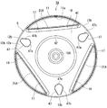
- FIG. 8 is a view of the boss portion of the second example of the impeller of the propeller fan according to the embodiment of the present invention as viewed from the suction side.
- the impeller 2A of the propeller fan 1 has an opening width of the suction side erection wall portion 12A decreasing from the center side to the outer peripheral side of the boss portion 5. It may have a drain hole 47.
- the drain holes 47 are provided on the outer peripheral portion of each suction side erection wall portion 12A.
- the drain hole 47 has an egg-shaped shape that extends toward the center side of the boss portion 5 or the inner peripheral side of the suction side erection wall portion 12A.
- the drain holes 47 are provided on the inner peripheral side and are convex toward the center side of the boss portion 5 or the inner peripheral side of the suction side erection wall portion 12A, and the first semi-arc-shaped portion 47a and the first semi-arc-shaped portion 47a. It has a wedge-shaped portion 47b that is continuous with the chord portion and whose opening width decreases at a substantially constant rate from the center side to the outer peripheral side of the boss portion 5.
- the drain hole 47 has a shape that is line-symmetric with respect to a virtual line extending in the radial direction of the propeller fan 1.
- the minimum opening width portion of the wedge-shaped portion 47b that is, the portion closest to the outer edge of the boss portion 5, is closed in a trapezoidal shape along the outer edge of the boss portion 5.
- the impeller 2A increases the area of the drainage hole 47 while relaxing the stress concentration at the root portion 31a of the front edge 31 of the blade portion 6 to increase the boss.
- Moisture such as rainwater accumulated in part 5 can be preferably drained.
- the drainage hole 47 is provided in the suction side erection wall portion 12A that widely spreads in the vicinity of the root portion 31a, it has a degree of freedom to secure a large opening area, and by extension, it is a factor of ice or hail. Even if there is, it can be easily drained. Further, the drain hole 47 has an egg shape extending toward the center of the boss portion 5.
- the water accumulated on the blowout side of the propeller fan 1 is easily drained from the propeller fan 1 along the inclination of the suction side erection wall portion 12A.
- the water is easily drained when going to the outside of the rotating propeller fan 1.
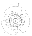
- FIG. 9 is a view of a third example of the impeller of the propeller fan according to the embodiment of the present invention as viewed from the suction side.
- FIG. 10 is a perspective view of a third example of the impeller of the propeller fan according to the embodiment of the present invention as viewed from the outlet side.
- FIG. 11 is a vertical sectional view of a third example of an impeller of a propeller fan according to an embodiment of the present invention.
- the impeller 2B (hereinafter, simply referred to as “impeller 2B”) of the third example of the propeller fan 1 according to the present embodiment is located away from the inner peripheral surface 11a of the tubular portion 11. It is provided with a plurality of suction-side erection wall portions 12B which are arranged in an annular portion and have a continuous annular connection portion 12b and are integrated by the annular portion 41B.
- the suction side erection wall portion 12B is a plate portion having a substantially uniform thickness curved in a concave shape from the suction side end 11s of the tubular portion 11 toward the blowout side.
- the concave bottom that is, the portion of the suction-side erection wall portion 12B farthest from the suction-side end 11s of the tubular portion 11, is closest to the center of the propeller fan 1.
- the annular portion 41B integrates a plurality of suction-side erection wall portions 12B.
- the annular portion 41B is a part of the suction side erection wall portion 12B, and extends from the suction side end 11s of the cylinder portion 11 toward the center of the cylinder portion 11.
- the portion of the plurality of suction side erection wall portions 12B near the cylinder portion 11 is connected to the cylinder portion 11 for each blade portion 6, while the portion of the plurality of suction side erection wall portions 12B far from the cylinder portion 11, in other words.
- the portions of the plurality of suction-side erection wall portions 12B near the rotating shaft mounting portion 15B are continuously connected by the annular portion 41B. That is, the plurality of suction-side erection wall portions 12B are arranged radially from the annular portion 41B arranged inside the tubular portion 11 toward the inner peripheral surface 11a of the tubular portion 11.
- the front end 16 of the connection portion 12b of the suction side erection wall portion 12B is continuous with the rear end 17 of the connection portion 12b of the suction side erection wall portion 12B located forward in the rotation direction of the propeller fan 1.
- the front end 16 and the rear end 17 of the adjacent suction side erection wall portions 12B are continuously connected.
- the front end 16 and the rear end edge 17 of the continuous suction side erection wall portion 12B have a curved shape, for example, the outside of the cylinder portion 11, that is, the center of curvature on the blade portion 6 side when viewed in the direction of the rotation center line of the propeller fan 1. It has an arc shape with.
- the front end 16 and the rear end edge 17 of these continuous suction-side erection wall portions 12B have an arc shape recessed inward toward the inside of the boss portion 5. Further, the front end 16 and the rear end 17 of the continuous suction side erection wall portion 12B have an arc shape recessed from the suction side end 11s of the tubular portion 11 toward the blowout side.
- the continuous front end 16 and the rear end 17 are connected to the outlet side erection wall portion 13B via the longitudinal wall portion 21B.
- the longitudinal wall portion 21B is curved in a concave arc shape toward the inside of the boss portion 5 following these continuous front end 16 and rear end 17, and extends with a substantially uniform thickness. There is. As shown in FIG. 10, the portion of the tubular portion 11 facing the vertical wall portion 21B, in other words, the portion of the tubular portion 11 facing the vertical wall portion 21B, hinders the support of the blade portion 6. It has a notch to the extent that it does not exist.
- the outlet side erection wall portion 13B is provided at a portion surrounded by the suction side erection wall portion 12B and the cylinder portion 11 when viewed in the direction of the rotation center line of the propeller fan 1.
- annular longitudinal wall portion 42 is provided on the inner edge of the annular portion 41B.
- the annular longitudinal wall portion 42 extends from the inner edge of the annular portion 41 toward the outlet side end 11b of the tubular portion 11.
- the annular longitudinal wall portion 42 may or may not reach the outlet side end 11b of the tubular portion 11.
- the outlet side end 42b of the annular longitudinal wall portion 42 is connected to the rotating shaft mounting portion 15B.
- the inner edge shape of the annular portion 41B may be a simple circular shape as shown in FIG. 9 or a polygonal shape when viewed in the direction of the rotation center line of the propeller fan 1.
- the polygonal inner edge shape includes, for example, a vertex arranged on a line segment that bisects the connection portion between the suction side erection wall portion 12B and the cylinder portion 11 in the rotation direction of the propeller fan 1, and the suction side erection wall portion. It has vertices arranged on a line segment that bisects the arc-shaped portion that separates the 12B and the tubular portion 11 from each other in the rotation direction of the propeller fan 1.
- the rotating shaft mounting portion 15B includes a flange portion 45 that is closer to the blowout side end 11b of the tubular portion 11 than the annular portion 41B shared by the plurality of suction side erection wall portions 12B.
- the flange portion 45 is a wall that extends in a direction perpendicular to the center of rotation of the propeller fan 1 and is connected to the outlet side end 42b of the annular longitudinal wall portion 42.
- the flange portion 45 is a wall that closes the boundary area inside the annular portion 41B.
- the impeller 2B is continuous with the root portion 31a of the front edge 31 of the blade portion 6 continuous with the suction side end 11s of the tubular portion 11 and the suction side end 11s of the tubular portion 11. It is provided with a suction side erection wall portion 12B. Therefore, the impeller 2B distributes the load generated at the root portion 31a of the front edge 31 of the blade portion 6 to the cylinder portion 11 of the boss portion 5 and the suction side erection wall portion 12B, so that the front edge 31 of the blade portion 6 The stress concentration at the root portion 31a is relaxed.
- the rear end 17 of the suction side erection wall portion 12B is located behind the root portion 31a of the front edge 31 of the nearest blade portion 6 in the rotation direction R of the propeller fan 1. doing. Therefore, the impeller 2B distributes the load generated at the root portion 31a of the front edge 31 of the blade portion 6 to the cylinder portion 11 of the boss portion 5 and the suction side erection wall portion 12B, so that the front edge 31 of the blade portion 6 The stress concentration at the root portion 31a is relaxed.
- the impeller 2B includes a root portion 31a of the front edge 31 of the blade portion 6 sandwiched between the front end 16 and the rear end 17 of the suction side erection wall portion 12B. Therefore, the impeller 2B distributes the load generated at the root portion 31a of the front edge 31 of the blade portion 6 to the cylinder portion 11 of the boss portion 5 and the suction side erection wall portion 12B, so that the front edge 31 of the blade portion 6 The stress concentration at the root portion 31a is more effectively relaxed.
- the impeller 2B includes a suction side erection wall portion 12B and a blowout side erection wall portion 13B that do not overlap in the direction along the rotation center line of the propeller fan 1. Therefore, the impeller 2B can be easily integrally molded by a mold that can be divided in the direction of the rotation center line.
- the impeller 2B includes a plurality of suction-side erection wall portions 12B which are arranged at a location away from the inner peripheral surface 11a of the tubular portion 11 and are integrated by an annular portion 41B which is continuous in an annular shape. ing. Therefore, in the impeller 2B, the stress generated at the root portion 31a of the front edge 31 of the blade portion 6 is dispersed in the cylinder portion 11 of the boss portion 5 and the suction side erection wall portion 12B, and the suction side erection wall portion 12B is dispersed. The stress to be applied is also applied to the annular portion 41B, and the stress concentration at the root portion 31a of the front edge 31 of the blade portion 6 is further relaxed.
- the impeller 2B according to the present embodiment has an arc shape in which the front end 16 and the rear end 17 of the adjacent suction side erection wall portions 12B are concavely recessed inward of the boss portion 5. Therefore, the impeller 2B increases the stress borne by the suction side erection wall portion 12B and the annular portion 41B, and further greatly relaxes the stress concentration at the root portion 31a of the front edge 31 of the blade portion 6.
- the stress concentration at the connecting portion between the root portion 31a of the front edge 31 of the blade portion 6 and the boss portion 5 is more effectively relaxed. it can.
Landscapes
- Engineering & Computer Science (AREA)
- Mechanical Engineering (AREA)
- General Engineering & Computer Science (AREA)
- Chemical & Material Sciences (AREA)
- Combustion & Propulsion (AREA)
- Structures Of Non-Positive Displacement Pumps (AREA)
- Other Air-Conditioning Systems (AREA)
Abstract
羽根部の前縁の付根部とボス部との接続部分における応力集中をより効果的に緩和可能なプロペラファンの羽根車を提供する。羽根車(2)は、ボス部(5)と、ボス部(5)の外周面から放射状に突出する複数の羽根部(6)と、を備えている。ボス部(5)は、外周面(5a)を有して吸込側端から吹出側端へ延びる筒部(11)と、筒部(11)の中心線に沿う方向を臨む吸込側端面(12a)を有し、かつ吸込側端(11s)に連続する接続部を有して筒部(11)の内側へ延びる複数の吸込側架設壁部(12)と、筒部(11)の中心線に沿う方向を臨む吹出側端面(13a)を有し、かつ吸込側架設壁部(12)よりも吹出側端(11b)に近く、筒部(11)の内側へ延びる複数の吹出側架設壁部(13)と、を備えている。それぞれの羽根部(6)の前縁(31)の付根部(31a)は、筒部(11)の吸込側端(11s)に連続している。
Description
本発明の実施形態は、プロペラファンの羽根車、送風機、および空気調和機の室外機に関する。
空気調和機の室外機の送風機として、プロペラファンが用いられている。プロペラファンは、羽根車と、羽根車の回転駆動力を発生させる電動機と、を備えている。羽根車は、筒状のボス部と、ボス部の外周面から放射状に突出する複数の羽根部と、を備えている。
ボス部は、電動機とプロペラファンとを繋ぐ回転軸が設けられる軸取付部と、軸取付部の外周面からボス部の内壁へ放射状に延びる複数のリブと、複数のリブの間を繋ぐ下流側架設壁部と、下流側架設壁部よりも上流側で複数のリブの間を繋ぐ上流側架設壁部と、を備えている。下流側架設壁部と上流側架設壁部とは、プロペラファンの回転中心線に沿う方向へ重ならない。上流側架設壁部は、羽根部の前縁の基端部の軸心側に設けられている。
プロペラファンの回転中、羽根部の前縁の付根部とボス部との接続部分には、最も大きい負荷が生じる。従来のプロペラファンであっても、羽根部の前縁の付根部とボス部との接続部分における応力集中を改善する余地が残されていた。
そこで、本発明は、羽根部の前縁の付根部とボス部との接続部分における応力集中をより効果的に緩和可能なプロペラファンの羽根車を提供することを目的とする。
本発明の実施形態に係るプロペラファンの羽根車は、ボス部と、前記ボス部の外周面から放射状に突出する複数の羽根部と、を備え、前記ボス部は、前記外周面を有して吸込側端から吹出側端へ延びる筒部と、前記筒部の中心線に沿う方向を臨む面を有し、かつ前記吸込側端に連続する接続部を有して前記筒部の内側へ延びる複数の吸込側架設壁部と、前記筒部の中心線に沿う方向を臨む面を有し、かつ前記吸込側架設壁部よりも前記吹出側端に近く、前記筒部の内側へ延びる複数の吹出側架設壁部と、を備え、それぞれの前記羽根部の前縁の付根部は、前記吸込側端に連続している。
また、本発明の実施形態に係る送風機は、前記プロペラファンと、前記プロペラファンを駆動する電動機と、を備えている。
さらに、本発明の実施形態に係る空気調和機の室外機は、前記送風機と、前記送風機によって流動する空気と熱交換する熱交換器と、を備えている。
本発明に係るプロペラファンの羽根車、送風機、および空気調和機の室外機の実施形態について図1から図11を参照して説明する。なお、複数の図面中、同一または相当する構成には同一の符号を付している。
図1は、本発明の実施形態に係る空気調和機の室外機の断面図である。
図1に示すように、本実施形態に係る空気調和機は室外機100と室内機(図示省略)とを含んでいる。室外機100は、筐体101と、筐体101の内部に電動機102を含む送風機103と、熱交換器105と、圧縮機106と、四方弁(図示省略)と、制御器(図示省略)と、を備えている。
筐体101は、側面を覆う側板111と、天井を覆う天板112と、底面を覆う底板113と、を備えている。筐体101の内部には仕切板115が設けられている。仕切板115は、筐体101の内部を機械室117と熱交換室118とに区画している。
側板111は室外機100内に外気を吸い込む複数の吸込孔111aを有している。
天板112の中央部には、側板111の吸込孔111aから室外機100内に吸い込まれた外気を室外機100の外に排気する吹出孔112aとベルマウス(図示省略)とが設けられている。
圧縮機106は、機械室117の底板113上に設置されている。また、圧縮機106は、熱交換器105よりも下方に配置されている。
熱交換器105は、熱交換室118の中央部に設置されている。
送風機103は、熱交換器105の上方に位置し、天板112の排気孔111aの近傍に設置されている。
室外機100は、冷媒配管(図示省略)を介して室内機に接続されている。冷凍サイクルの運転が開始されると圧縮機106が駆動される。圧縮機106は、冷媒配管に冷媒を流通させて熱交換器105へ導く。同時に送風機103の運転が開始される。電動機102はプロペラファン1を回転駆動させる。
外気は、筐体101の側面の吸込孔111aから熱交換室118に導かれ、熱交換器105を通過して、熱交換器105内の冷媒と熱交換する。熱交換器105で熱交換された空気は、送風機103を介してベルマウスに案内され、筐体100の上方の吹出孔112aから室外機100の外部へ排出される。
図2は、本発明の実施形態に係るプロペラファンの羽根車を吸込側から見た斜視図である。
図3は、本発明の実施形態に係るプロペラファンの羽根車を吹出側から見た斜視図である。
図2および図3に示すように、本実施形態に係るプロペラファン1は、図2および図3中に実線矢印で示す回転方向Rへ回転して図2および図3中に実線矢印で示す流れ方向Fへ流体、もっぱら空気を流動させる。なお、プロペラファン1を回転方向Rの反対方向へ回転させると、流体は流れ方向Fの反対方向へ流動する。プロペラファン1は、例えば空気調和機の室外機に適用されて、室外熱交換器へ空気を吹き付ける用途に用いられる。
プロペラファン1は、いわゆる軸流ファンである。プロペラファン1は、羽根車2と、羽根車2を回転駆動させる電動機(図示省略)と、を備えている。
電動機は、羽根車2へ回転駆動力を伝達する出力軸(図示省略)を備えている。出力軸は、羽根車2の回転中心である。
図4は、本発明の実施形態に係るプロペラファンの羽根車の縦断面図である。
図2および図3に加えて図4に示すように、本実施形態に係るプロペラファン1の羽根車2は、いわゆる軸流式(Axial flow impeller)である。羽根車2は、単にプロペラとも呼ばれる。羽根車2は、ボス部5と、ボス部5の外周面5aから放射状に突出する複数の羽根部6と、を備えている。羽根車2は、例えば樹脂で一体成形されている。
複数の羽根部6は、ボス部5の外周面5aに沿って羽根車2の周方向、つまりプロペラファン1の回転方向Rへ等間隔に並んでいる。羽根車2は、例えば3つの羽根部6を備えている。この場合、3つの羽根部6は、中心角120度毎に並んでいる。それぞれの羽根部6はプロペラファン1の回転方向において吸込み側に傾斜してボス部5の外周面5aに配置されている。羽根部6の前縁部31の付根部31aは、ボス部5の吸込側端11sに一致している。
ボス部5は、ボス部5の外周面5aを有して吸込側端11sから吹出側端11bへ延びる筒部11と、筒部11の中心線に沿う方向を臨む吸込側端面12aを有し、かつボス部5の吸込側端11sに連続する接続部12bを有して筒部11の中心へ向かって延びる複数の吸込側架設壁部12と、筒部11の中心線に沿う方向を臨む吹出側端面13aを有し、かつ吸込側架設壁部12よりも吹出側端11bに近く、筒部11の中心へ向かって延びる複数の吹出側架設壁部13と、複数の吸込側架設壁部12および複数の吹出側架設壁部13を介して筒部11の中心に設けられる回転軸取付部15と、を備えている。
回転軸取付部15は、ボス部5の回転中心線上、かつ羽根車2の回転中心線上に配置されている。回転軸取付部15には、回転軸が固定される。羽根車2は、回転軸に固定される回転軸取付部15を介して電動機に接続されている。回転軸取付部15は、挿入された回転軸を固定するものであっても良いし、インサート成形によって回転軸に一体化されるものであっても良い。
複数の吸込側架設壁部12は、筒部11の吸込側端11sから筒部11の中心へ向かって延びる実質的に一様な厚さの平板部分である。それぞれの吸込側架設壁部12は、プロペラファン1の回転方向Rにおいて前方に位置する前端16と、前端16より後ろに位置する後端17と、を有している。それぞれの吸込側架設壁部12の外縁は、筒部11の吸込側端11sに連続して接続されている。
複数の吹出側架設壁部13は、筒部11の吹出側端11bから筒部11の中心へ向かって延びる実質的に一様な厚さの平板部分である。それぞれの吹出側架設壁部13は、プロペラファン1の回転方向Rにおいて前方に位置する前端18と、前端18より後ろに位置する後端19と、を有している。それぞれの吹出側架設壁部13の外縁は、筒部11の吹出側端11bに連続している。なお、吹出側架設壁部13の外縁は、筒部11の内部に位置されても良く、吹出側端11bに連続されていなくても良い。
複数の吸込側架設壁部12と複数の吹出側架設壁部13とは、プロペラファン1の回転方向Rにおいて交互に配置されている。複数の吸込側架設壁部12と複数の吹出側架設壁部13とは、プロペラファン1の回転中心線に沿う方向において重ならない。吸込側架設壁部12、吹出側架設壁部13、および羽根部6は同数設けられている。吸込側架設壁部12、吹出側架設壁部13、および羽根部6は、プロペラファン1の回転中心の回りに規則的に並んでいる。例えば、本実施形態のように、吸込側架設壁部12、吹出側架設壁部13、および羽根部6が3ずつ設けられている場合には、複数の吸込側架設壁部12、複数の吹出側架設壁部13、および複数の羽根部6の相互の位置関係および寸法関係は、プロペラファン1の回転中心の回りに120度毎に同じである。
プロペラファン1の回転中心線方向視において隣り合う吸込側架設壁部12と吹出側架設壁部13との間には、プロペラファン1の回転中心線方向に延びる縦通壁部21が設けられている。縦通壁部21は、実質的に一様な厚さを有している。縦通壁部21は複数ある。半数の縦通壁部21は、それぞれの吸込側架設壁部12の後端17とそれぞれの吹出側架設壁部13の前縁18とから構成され、他の縦通壁部21は、それぞれの吸込側架設壁部12の前端16とそれぞれの吹出側架設壁部13の後縁19とから構成されている。
縦通壁部21は、筒部11の内周面11aと回転軸取付部15との間に架け渡されている。複数の縦通壁部21は、回転軸取付部15から筒部11へ放射状に延びている。
換言すると、吸込側架設壁部12は、隣り合う縦通壁部21の吸込側端21s、筒部11の吸込側端11s、および回転軸取付部15の吸込側端15sに渡り、回転軸取付部15から筒部11の吸込側端11sに向かって扇形状に拡がっている。回転軸取付部15は、扇形状の吸込側架設壁部12の要にあたる。吹出側架設壁部13は、隣り合う縦通壁部21の吹出側端21b、筒部11の吹出側端11b、および回転軸取付部15の吹出側端15bに渡り、回転軸取付部15の吹出側端15bから筒部11の吹出側架設壁部に向かって扇形状に拡がっている。回転軸取付部15は、扇形状の吹出側架設壁部13の要にあたる。つまり、複数の吸込側架設壁部12と複数の吹出側架設壁部13とは、回転軸取付部15を中心に、交互に放射状に配置されている。
吸込側架設壁部12の接続部12bの後端17は、プロペラファン1の回転方向において、最も近い羽根部6の前縁31の付根部31aより後ろに位置している。図2においては、吸込側架設壁部12の後端17は、最も近い羽根部6の前縁31の付根部31aより後ろに位置している。
吸込側架設壁部12の接続部12bの前端16は、プロペラファン1の回転方向において、最も近い羽根部6の前縁31の付根部31aに一致しても良いし、最も近い羽根部6の前縁31の付根部31aより後ろに位置しても良いし、最も近い羽根部6の前縁31の付根部31aより前に位置しても良い。図2においては、吸込側架設壁部12の前端16は、最も近い羽根部6の前縁31の付根部31aより前に位置している。
なお、羽根部6の前縁31の付根部31aは、吸込側架設壁部12の接続部12bの前端16と後端17との間に挟まれていることが好ましい。換言すると、プロペラファン1の回転方向において、吸込側架設壁部12の前端16および後端17は、羽根部6の前縁31の付根部31aを挟んでいることが好ましい。
そして、それぞれの羽根部6の前縁31の付根部31aは、筒部11の吸込側端11sに連続している。つまり、羽根部6の前縁31の付根部31aと吸込側架設壁部12の最外縁とは、プロペラファン1の回転方向へオフセットすることなく、筒部11の吸込側端11sを間に挟んで向き合っている。
以上のように、本実施形態に係る羽根車2は、筒部11の吸込側端11sに連続する羽根部6の前縁31の付根部31aと、筒部11の吸込側端11sに連続する吸込側架設壁部12と、を備えている。そのため、羽根車2は、羽根部6の前縁31の付根部31aに発生する負荷をボス部5の筒部11、吸込側架設壁部12、および縦通壁部21に分散させて、羽根部6の前縁31の付根部31aにおける応力集中を緩和させる。
なお、筒部11の吸込側端11sが、羽根部6の前縁31の付根部31aと吸込側架設壁部12の最外縁との間になく、プロペラファン1の吸込側へ突出して、羽根部6の前縁31の付根部31aと吸込側架設壁部12の最外縁との間に挟まれる箇所から離れている場合には、吸込側架設壁部12が分散する負荷の割合が低下する。つまり、羽根部6の前縁31の付根部31aにおける応力集中の改善は不十分に留まる。
また、吸込側架設壁部12が羽根部6の前縁31の付根部31aよりもプロペラファン1の回転方向Rへオフセットしている場合にも、吸込側架設壁部12が分散する負荷の割合が低下する。換言すると、プロペラファン1の回転方向において、吸込側架設壁部12の後端17が最も近い羽根部6の前縁31の付根部31aより前側に位置して、羽根部6の前縁31の付根部31aが吸込側架設壁部12の前端16と後端17との間に挟まれていない場合には、吸込側架設壁部12が分散する負荷の割合が低下する。つまり、羽根部6の前縁31の付根部31aにおける応力集中の改善は不十分に留まる。
ただし、プロペラファン1の回転方向において、羽根部6の前縁31の付根部31aが吸込側架設壁部12の前端16と後端17との間に挟まれていなくても、吸込側架設壁部12の前端16が最も近い羽根部6の前縁31の付根部31aより後ろ側に位置する場合には、吸込側架設壁部12は、羽根部6の前縁31の付根部31aに発生する負荷を意図通りに負担して、羽根部6の前縁31の付根部31aにおける応力集中を緩和させる。このような改善は、プロペラファン1の回転方向Rにおいて、前方に位置する付根部31aに発生する負荷が、筒部11を介して後ろ側に配置される吸込側架設壁部12で負担されることによるものと考えられる。
また、本実施形態に係る羽根車2では、吸込側架設壁部12の後端17が、プロペラファン1の回転方向Rにおいて、最も近い羽根部6の前縁31の付根部31aより後ろに位置している。そのため、羽根車2は、羽根部6の前縁31の付根部31aに発生する負荷をボス部5の筒部11および吸込側架設壁部12に分散させて、羽根部6の前縁31の付根部31aにおける応力集中を緩和させる。
さらに、本実施形態に係る羽根車2は、吸込側架設壁部12の前端16と後端17との間に挟まれる、羽根部6の前縁31の付根部31aを備えている。そのため、羽根車2は、羽根部6の前縁31の付根部31aに発生する負荷をボス部5の筒部11および吸込側架設壁部12に分散させて、羽根部6の前縁31の付根部31aにおける応力集中をより効果的に緩和させる。
また、本実施形態に係る羽根車2は、プロペラファン1の回転中心線に沿う方向において重ならない、吸込側架設壁部12と吹出側架設壁部13とを備えている。そのため、羽根車2は、その回転中心線方向へ分割可能な金型によって、容易に一体成型することができる。
次に、本実施形態に係る羽根車2の他の例を説明する。なお、各例で説明する羽根車2A、および2Bにおいて、共通する構成には同一の符号を付し、重複する説明は省略する。
図5は、本発明の実施形態に係るプロペラファンの羽根車の第二例を吸込側から見た斜視図である。
図6は、本発明の実施形態に係るプロペラファンの羽根車の第二例を吹出側から見た斜視図である。
図7は、本発明の実施形態に係るプロペラファンの羽根車の第二例の縦断面図である。
図5から図7に示すように、本実施形態に係るプロペラファン1の第二例の羽根車2A(以下、単に「羽根車2A」と呼ぶ。)は、筒部11の内周面11aから離れた場所に配置されて環状に連続する接続部12bを有して環状部41で一体化される複数の吸込側架設壁部12Aを備えている。
吸込側架設壁部12Aは、筒部11の吸込側端11sから吹出側へ向かって凹形状に湾曲した実質的に一様な厚さの板部分である。凹形状の底、つまり吸込側架設壁部12Aの最も筒部11の吸込側端11sから遠い部位は、プロペラファン1の中心に最も近い。
環状部41は、複数の吸込側架設壁部12Aを一体化させている。環状部41は、吸込側架設壁部12Aの一部であって、筒部11の吸込側端11sから吹出側へ向かって凹形状に湾曲している。複数の吸込側架設壁部12Aの筒部11に近い部分は、羽根部6毎に筒部11に繋がっている一方で、複数の吸込側架設壁部12Aの筒部11から遠い部分、換言すると、複数の吸込側架設壁部12Aの回転軸取付部15Aに近い部分は、環状部41によって一続きに繋がっている。つまり、複数の吸込側架設壁部12Aは、筒部11の内側に配置される環状部41から筒部11の内周面11aへ向かって放射状に配置されている。
ある吸込側架設壁部12Aの接続部12bの前端16は、プロペラファン1の回転方向において前方に位置する吸込側架設壁部12Aの接続部12bの後端17に連続している。換言すると、隣り合う吸込側架設壁部12Aの前端16と後端17とは、一続きに繋がっている。この連続する吸込側架設壁部12Aの前端16と後端17とは、プロペラファン1の回転中心線方向に見て、直線形状を有し、かつ筒部11の吸込側端11sから吹出側へ向かって凹形状に窪んだ円弧形状を有している。これら連続する前端16と後端17とは、縦通壁部21Aを介して吹出側架設壁部13Aに繋がっている。縦通壁部21Aは、これら連続する前端16と後端17とに続いてプロペラファン1の回転中心線方向へ平板状に延びている。なお、筒部11のうち縦通壁部21Aを臨む部分、換言すると、筒部11のうち縦通壁部21Aに対面している部分は、羽根部6の支持に支障のない範囲で切り欠かれていても良い。この切欠きによりプロペラファン1の軽量化を図ることができる。
吹出側架設壁部13Aは、プロペラファン1の回転中心線方向に見て、吸込側架設壁部12Aと筒部11とに囲まれた部位に設けられている。
環状部41の内縁には、環状縦通壁部42が設けられている。環状縦通壁部42は、環状部41の内縁から筒部11の吹出側端11bへ向かって延びている。環状縦通壁部42は、筒部11の吹出側端11bに達していても良いし、達していなくても良い。環状縦通壁部42の吹出側端42bは、回転軸取付部15Aに繋がっている。
環状部41の内縁形状は、プロペラファン1の回転中心線方向に見て、単なる円形であっても良いし、図5のような多角形状であっても良い。多角形状の内縁形状は、例えば、吸込側架設壁部12Aと筒部11との接続部分をプロペラファン1の回転方向へ二等分する線分上に配置される頂点と、吸込側架設壁部12Aと筒部11との非接続に隔てる円弧形状部をプロペラファン1の回転方向へ二等分する線分上に配置される頂点と、を有している。本実施形態のように、吸込側架設壁部12が3つ設けられている場合には、環状部41の内縁形状は、六角形を描く。
回転軸取付部15Aは、複数の吸込側架設壁部12Aが共有する環状部41よりも筒部11の吹出側端11bに近いフランジ部45を備えている。フランジ部45は、プロペラファン1の回転中心に直行する方向へ広がる壁であり、環状縦通壁部42の吹出側端42bに繋がっている。フランジ部45は、環状部41の内側の境域を塞ぐ壁である。
以上のように、本実施形態に係る羽根車2Aは、筒部11の吸込側端11sに連続する羽根部6の前縁31の付根部31aと、筒部11の吸込側端11sに連続する吸込側架設壁部12Aと、を備えている。そのため、羽根車2Aは、羽根部6の前縁31の付根部31aに発生する負荷をボス部5の筒部11および吸込側架設壁部12Aに分散させて、羽根部6の前縁31の付根部31aにおける応力集中を緩和させる。
また、本実施形態に係る羽根車2Aは、吸込側架設壁部12Aの後端17が、プロペラファン1の回転方向Rにおいて、最も近い羽根部6の前縁31の付根部31aより後ろに位置している。そのため、羽根車2Aは、羽根部6の前縁31の付根部31aに発生する負荷をボス部5の筒部11および吸込側架設壁部12Aに分散させて、羽根部6の前縁31の付根部31aにおける応力集中を緩和させる。
さらに、本実施形態に係る羽根車2Aは、吸込側架設壁部12Aの前端16と後端17との間に挟まれる、羽根部6の前縁31の付根部31aを備えている。そのため、羽根車2Aは、羽根部6の前縁31の付根部31aに発生する負荷をボス部5の筒部11および吸込側架設壁部12Aに分散させて、羽根部6の前縁31の付根部31aにおける応力集中をより効果的に緩和させる。
また、本実施形態に係る羽根車2Aは、プロペラファン1の回転中心線に沿う方向において重ならない、吸込側架設壁部12Aと吹出側架設壁部13Aとを備えている。そのため、羽根車2Aは、その回転中心線方向へ分割可能な金型によって、容易に一体成型することができる。
さらに、本実施形態に係る羽根車2Aは、筒部11の内周面11aから離れた場所に配置されて環状に連続する環状部41で一体化される複数の吸込側架設壁部12Aを備えている。そのため、羽根車2Aは、羽根部6の前縁31の付根部31aに発生する応力をボス部5の筒部11および吸込側架設壁部12Aに分散させるとともに、吸込側架設壁部12Aが分散する応力を環状部41にも負担させて、羽根部6の前縁31の付根部31aにおける応力集中をより大きく緩和させる。
図8は、本発明の実施形態に係るプロペラファンの羽根車の第二例のボス部を吸込側から見た図である。
図8に示すように、本実施形態に係るプロペラファン1の羽根車2Aは、羽根車2Aは、吸込側架設壁部12Aにボス部5の中心側から外周側へ向かって開口幅が減少する水抜き孔47を有していても良い。
水抜き孔47は、それぞれの吸込側架設壁部12Aの外周部分に設けられている。水抜き孔47は、ボス部5の中心側、もしくは吸込側架設壁部12Aの内周側へ広がる卵形の形状を有している。水抜き孔47は、内周側に設けられてボス部5の中心側、もしくは吸込側架設壁部12Aの内周側へ凸の第一半円弧形状部47aと、第一半円弧形状部47aの弦の部分に連続し、かつボス部5の中心側から外周側へ向かって開口幅が実質的に一定の割合で減少する楔形状部47bと、を有している。水抜き孔47は、プロペラファン1の径方向へ延びる仮想線に対して線対称な形状を有している。
楔形状部47bの最小開口幅部分、つまりボス部5の外縁に最も近い部分は、ボス部5の外縁に沿って台形状に閉じられている。
上記のような水抜き孔47の構成とすることで、羽根車2Aは、羽根部6の前縁31の付根部31aにおける応力集中を緩和させつつ、水抜き孔47の面積を大きくしてボス部5に溜る雨水などの水分を好適に排水できる。水抜き孔47は、付根部31a近傍に大きく広がる吸込側架設壁部12Aに設けられているため、開口面積を大きく確保する自由度を有し、ひいては氷や雹の要因固体の状態の水分であっても、容易に排水することができる。さらに、水抜き孔47は、ボス部5の中心へ向かって広がっている卵形状を有している。そのため、プロペラファン1の吹き出し側に溜る水分は、吸込側架設壁部12Aの傾斜に沿ってプロペラファン1の、容易に排水される。また、水分は、回転するプロペラファン1の外側へ向かう際に、容易に排水される。
図9は、本発明の実施形態に係るプロペラファンの羽根車の第三例を吸込側から見た図である。
図10は、本発明の実施形態に係るプロペラファンの羽根車の第三例を吹出側から見た斜視図である。
図11は、本発明の実施形態に係るプロペラファンの羽根車の第三例の縦断面図である。
図9に示すように、本実施形態に係るプロペラファン1の第三例の羽根車2B(以下、単に「羽根車2B」と呼ぶ。)は、筒部11の内周面11aから離れた場所に配置されて環状に連続する接続部12bを有して環状部41Bで一体化される複数の吸込側架設壁部12Bを備えている。
なお、羽根車2Bの縦断面形状は、図7に示される羽根車2Aの断面形状に準ずるので図示を省略する。
吸込側架設壁部12Bは、筒部11の吸込側端11sから吹出側へ向かって凹形状に湾曲した実質的に一様な厚さの板部分である。凹形状の底、つまり吸込側架設壁部12Bの最も筒部11の吸込側端11sから遠い部位は、プロペラファン1の中心に最も近い。
環状部41Bは、複数の吸込側架設壁部12Bを一体化させている。環状部41Bは、吸込側架設壁部12Bの一部であって、筒部11の吸込側端11sから筒部11の中心へ向かって延びている。複数の吸込側架設壁部12Bの筒部11に近い部分は、羽根部6毎に筒部11に繋がっている一方で、複数の吸込側架設壁部12Bの筒部11から遠い部分、換言すると、複数の吸込側架設壁部12Bの回転軸取付部15Bに近い部分は、環状部41Bによって一続きに繋がっている。つまり、複数の吸込側架設壁部12Bは、筒部11の内側に配置される環状部41Bから筒部11の内周面11aへ向かって放射状に配置されている。
ある吸込側架設壁部12Bの接続部12bの前端16は、プロペラファン1の回転方向において前方に位置する吸込側架設壁部12Bの接続部12bの後端17に連続している。換言すると、隣り合う吸込側架設壁部12Bの前端16と後端17とは、一続きに繋がっている。この連続する吸込側架設壁部12Bの前端16と後端縁17とは、プロペラファン1の回転中心線方向に見て、曲線形状、例えば筒部11の外側、つまり羽根部6側に曲率中心を有する円弧形状を有している。換言すると、これら連続する吸込側架設壁部12Bの前端16と後端縁17とは、ボス部5の内側へ向かって凹形状に窪んだ円弧形状を有している。また、この連続する吸込側架設壁部12Bの前端16と後端17とは、筒部11の吸込側端11sから吹出側へ向かって凹形状に窪んだ円弧形状を有している。これら連続する前端16と後端17とは、縦通壁部21Bを介して吹出側架設壁部13Bに繋がっている。縦通壁部21Bは、これら連続する前端16と後端17とに続いてボス部5の内側へ向かって凹形状に窪んだ円弧形状に湾曲して実質的に一様な厚さで延びている。図10に示すように、筒部11のうち縦通壁部21Bを臨む部分、換言すると、筒部11のうち縦通壁部21Bに対面している部分は、羽根部6の支持に支障のない範囲で切欠きを有している。
吹出側架設壁部13Bは、プロペラファン1の回転中心線方向に見て、吸込側架設壁部12Bと筒部11とに囲まれた部位に設けられている。
環状部41Bの内縁には、環状縦通壁部42が設けられている。環状縦通壁部42は、環状部41の内縁から筒部11の吹出側端11bへ向かって延びている。環状縦通壁部42は、筒部11の吹出側端11bに達していても良いし、達していなくても良い。環状縦通壁部42の吹出側端42bは、回転軸取付部15Bに繋がっている。
環状部41Bの内縁形状は、プロペラファン1の回転中心線方向に見て、図9のような単なる円形であっても良いし、多角形状であっても良い。多角形状の内縁形状は、例えば、吸込側架設壁部12Bと筒部11との接続部分をプロペラファン1の回転方向へ二等分する線分上に配置される頂点と、吸込側架設壁部12Bと筒部11との非接続に隔てる円弧形状部をプロペラファン1の回転方向へ二等分する線分上に配置される頂点と、を有している。
回転軸取付部15Bは、複数の吸込側架設壁部12Bが共有する環状部41Bよりも筒部11の吹出側端11bに近いフランジ部45を備えている。フランジ部45は、プロペラファン1の回転中心に直行する方向へ広がる壁であり、環状縦通壁部42の吹出側端42bに繋がっている。フランジ部45は、環状部41Bの内側の境域を塞ぐ壁である。
以上のように、本実施形態に係る羽根車2Bは、筒部11の吸込側端11sに連続する羽根部6の前縁31の付根部31aと、筒部11の吸込側端11sに連続する吸込側架設壁部12Bと、を備えている。そのため、羽根車2Bは、羽根部6の前縁31の付根部31aに発生する負荷をボス部5の筒部11および吸込側架設壁部12Bに分散させて、羽根部6の前縁31の付根部31aにおける応力集中を緩和させる。
また、本実施形態に係る羽根車2Bは、吸込側架設壁部12Bの後端17が、プロペラファン1の回転方向Rにおいて、最も近い羽根部6の前縁31の付根部31aより後ろに位置している。そのため、羽根車2Bは、羽根部6の前縁31の付根部31aに発生する負荷をボス部5の筒部11および吸込側架設壁部12Bに分散させて、羽根部6の前縁31の付根部31aにおける応力集中を緩和させる。
さらに、本実施形態に係る羽根車2Bは、吸込側架設壁部12Bの前端16と後端17との間に挟まれる、羽根部6の前縁31の付根部31aを備えている。そのため、羽根車2Bは、羽根部6の前縁31の付根部31aに発生する負荷をボス部5の筒部11および吸込側架設壁部12Bに分散させて、羽根部6の前縁31の付根部31aにおける応力集中をより効果的に緩和させる。
また、本実施形態に係る羽根車2Bは、プロペラファン1の回転中心線に沿う方向において重ならない、吸込側架設壁部12Bと吹出側架設壁部13Bとを備えている。そのため、羽根車2Bは、その回転中心線方向へ分割可能な金型によって、容易に一体成型することができる。
さらに、本実施形態に係る羽根車2Bは、筒部11の内周面11aから離れた場所に配置されて環状に連続する環状部41Bで一体化される複数の吸込側架設壁部12Bを備えている。そのため、羽根車2Bは、羽根部6の前縁31の付根部31aに発生する応力をボス部5の筒部11および吸込側架設壁部12Bに分散させるとともに、吸込側架設壁部12Bが分散する応力を環状部41Bにも負担させて、羽根部6の前縁31の付根部31aにおける応力集中をより大きく緩和させる。
また、本実施形態に係る羽根車2Bは、隣り合う吸込側架設壁部12Bの前端16と後端17とが、ボス部5の内側へ凹形状に窪んだ円弧形状を有している。そのため、羽根車2Bは、吸込側架設壁部12Bおよび環状部41Bが負担する応力を増大させて、羽根部6の前縁31の付根部31aにおける応力集中をさらに大きく緩和させる。
したがって、本実施形態に係るプロペラファン1の羽根車2、2A、2Bによれば、羽根部6の前縁31の付根部31aとボス部5との接続部分における応力集中をより効果的に緩和できる。
本発明のいくつかの実施形態を説明したが、これらの実施形態は、例として提示したものであり、発明の範囲を限定することは意図していない。これら新規な実施形態は、その他の様々な形態で実施されることが可能であり、発明の要旨を逸脱しない範囲で、種々の省略、置き換え、変更を行うことができる。これら実施形態やその変形は、発明の範囲や要旨に含まれるとともに、特許請求の範囲に記載された発明とその均等の範囲に含まれる。
1…プロペラファン、2、2A…羽根車、5…ボス部、5a…ボス部の外周面、6…羽根部、11…筒部、11a…筒部の内周面、11s…筒部の吸込側端、11b…筒部の吹出側端、12、12A、12B…吸込側架設壁部、12a…吸込側端面、12b…吸込側架設壁部の接続部、13、13A、13B…吹出側架設壁部、13a…吹出側端面、15、15A…回転軸取付部、15s…回転軸取付部の吸込側端、15b…回転軸取付部の吹出側端、16…吸込側架設壁部の前端、17…吸込側架設壁部の後端、18…吹出側架設壁部の前縁、19…吹出側架設壁部の後縁、21、21A、21B…縦通壁部、21s…縦通壁部の吸込側端、21b…縦通壁部の吹出側端、31…羽根部の前縁、31a…羽根部の前縁の付根部、41…環状部、42…環状縦通壁部、42b…環状縦通壁部の吹出側端、45…フランジ部、47…水抜き孔、48…切欠き。
Claims (9)
- ボス部と、
前記ボス部の外周面から放射状に突出する複数の羽根部と、を備え、
前記ボス部は、
前記外周面を有して吸込側端から吹出側端へ延びる筒部と、
前記筒部の中心線に沿う方向を臨む面を有し、かつ前記吸込側端に連続する接続部を有して前記筒部の内側へ延びる複数の吸込側架設壁部と、
前記筒部の中心線に沿う方向を臨む面を有し、かつ前記吸込側架設壁部よりも前記吹出側端に近く、前記筒部の内側へ延びる複数の吹出側架設壁部と、を備え、
それぞれの前記羽根部の前縁の付根部は、前記吸込側端に連続するプロペラファンの羽根車。 - 前記吸込側架設壁部は、前記接続部の前記プロペラファンの回転方向において前方に位置する前端と、前記前端より後ろに位置する後端と、を有し、
前記吸込側架設壁部の前記後端は、前記プロペラファンの回転方向において、最も近い前記羽根部の前記前縁の前記付根部より後ろに位置する請求項1に記載のプロペラファンの羽根車。 - 前記羽根部の前記前縁の前記付根部は、前記吸込側架設壁部の前記前端と前記後端との間に挟まれる請求項2に記載のプロペラファンの羽根車。
- 前記吸込側架設壁部と前記吹出側架設壁部とは、前記プロペラファンの回転中心線に沿う方向において重ならない請求項1から3のいずれか1項に記載のプロペラファンの羽根車。
- 前記複数の吸込側架設壁部は、前記筒部の内周面から離れた場所に配置されて環状に連続する環状部で一体化されている請求項1から4のいずれか1項に記載のプロペラファンの羽根車。
- 隣り合う前記吸込側架設壁部の前記前端と前記後端とが、前記ボス部の内側へ凹形状に窪んだ曲線形状を有する請求項5に記載のプロペラファンの羽根車。
- 前記吸込側架設壁部は、前記吸込側端から吹出側へ向かって凹形状に湾曲し、かつ前記ボス部の中心側から外周側へ向かって開口幅が減少する水抜き孔を有する請求項5または6に記載のプロペラファンの羽根車。
- 請求項1から7のいずれか1項に記載のプロペラファンと、
前記プロペラファンを駆動する電動機と、を備える送風機。 - 請求項8に記載の送風機と、
前記送風機によって流動する空気と熱交換する熱交換器と、を備える空気調和機の室外機。
Priority Applications (4)
| Application Number | Priority Date | Filing Date | Title |
|---|---|---|---|
| PCT/JP2019/029948 WO2021019710A1 (ja) | 2019-07-31 | 2019-07-31 | プロペラファンの羽根車、送風機、および空気調和機の室外機 |
| CN201980098803.6A CN114207290B (zh) | 2019-07-31 | 2019-07-31 | 螺旋桨式风扇的叶轮、送风机以及空调机的室外机 |
| EP19939652.4A EP4006355A4 (en) | 2019-07-31 | 2019-07-31 | IMPELLER FOR PROPELLER FAN, BLOWER AND OUTDOOR UNIT FOR AIR CONDITIONING |
| JP2021536533A JP7245339B2 (ja) | 2019-07-31 | 2019-07-31 | プロペラファンの羽根車、送風機、および空気調和機の室外機 |
Applications Claiming Priority (1)
| Application Number | Priority Date | Filing Date | Title |
|---|---|---|---|
| PCT/JP2019/029948 WO2021019710A1 (ja) | 2019-07-31 | 2019-07-31 | プロペラファンの羽根車、送風機、および空気調和機の室外機 |
Publications (1)
| Publication Number | Publication Date |
|---|---|
| WO2021019710A1 true WO2021019710A1 (ja) | 2021-02-04 |
Family
ID=74229457
Family Applications (1)
| Application Number | Title | Priority Date | Filing Date |
|---|---|---|---|
| PCT/JP2019/029948 Ceased WO2021019710A1 (ja) | 2019-07-31 | 2019-07-31 | プロペラファンの羽根車、送風機、および空気調和機の室外機 |
Country Status (4)
| Country | Link |
|---|---|
| EP (1) | EP4006355A4 (ja) |
| JP (1) | JP7245339B2 (ja) |
| CN (1) | CN114207290B (ja) |
| WO (1) | WO2021019710A1 (ja) |
Cited By (1)
| Publication number | Priority date | Publication date | Assignee | Title |
|---|---|---|---|---|
| WO2025009070A1 (ja) * | 2023-07-04 | 2025-01-09 | 三菱電機株式会社 | プロペラファン及び空気調和機 |
Families Citing this family (1)
| Publication number | Priority date | Publication date | Assignee | Title |
|---|---|---|---|---|
| JP2025171984A (ja) * | 2024-05-10 | 2025-11-20 | 日本キヤリア株式会社 | 羽根車 |
Citations (5)
| Publication number | Priority date | Publication date | Assignee | Title |
|---|---|---|---|---|
| JPS5870497U (ja) * | 1981-11-06 | 1983-05-13 | アイシン精機株式会社 | 内燃機関用冷却フアン |
| JPS611897A (ja) * | 1984-01-30 | 1986-01-07 | Hitachi Ltd | エアコンデイシヨナ用プロペラフアン |
| JPH0674196A (ja) * | 1992-08-26 | 1994-03-15 | Hitachi Ltd | プロペラファンおよびこれを備えた空気調和機 |
| JP2005188325A (ja) * | 2003-12-24 | 2005-07-14 | Calsonic Kansei Corp | モータファンのアンバランス修正構造 |
| JP2017053301A (ja) | 2015-09-11 | 2017-03-16 | ジョンソンコントロールズ ヒタチ エア コンディショニング テクノロジー(ホンコン)リミテッド | プロペラファン及び空気調和機の室外機 |
Family Cites Families (5)
| Publication number | Priority date | Publication date | Assignee | Title |
|---|---|---|---|---|
| JPH05256299A (ja) * | 1992-03-13 | 1993-10-05 | Toshiba Corp | 送風機 |
| JP4388992B1 (ja) * | 2008-10-22 | 2009-12-24 | シャープ株式会社 | プロペラファン、流体送り装置および成型金型 |
| JP5611277B2 (ja) * | 2012-06-20 | 2014-10-22 | 三菱電機株式会社 | 送風機、室外機及び冷凍サイクル装置 |
| KR102112888B1 (ko) * | 2012-08-31 | 2020-05-19 | 샤프 가부시키가이샤 | 송풍 장치 |
| JP2019060322A (ja) * | 2017-09-28 | 2019-04-18 | 日本電産株式会社 | 軸流ファン |
-
2019
- 2019-07-31 WO PCT/JP2019/029948 patent/WO2021019710A1/ja not_active Ceased
- 2019-07-31 JP JP2021536533A patent/JP7245339B2/ja active Active
- 2019-07-31 EP EP19939652.4A patent/EP4006355A4/en active Pending
- 2019-07-31 CN CN201980098803.6A patent/CN114207290B/zh active Active
Patent Citations (5)
| Publication number | Priority date | Publication date | Assignee | Title |
|---|---|---|---|---|
| JPS5870497U (ja) * | 1981-11-06 | 1983-05-13 | アイシン精機株式会社 | 内燃機関用冷却フアン |
| JPS611897A (ja) * | 1984-01-30 | 1986-01-07 | Hitachi Ltd | エアコンデイシヨナ用プロペラフアン |
| JPH0674196A (ja) * | 1992-08-26 | 1994-03-15 | Hitachi Ltd | プロペラファンおよびこれを備えた空気調和機 |
| JP2005188325A (ja) * | 2003-12-24 | 2005-07-14 | Calsonic Kansei Corp | モータファンのアンバランス修正構造 |
| JP2017053301A (ja) | 2015-09-11 | 2017-03-16 | ジョンソンコントロールズ ヒタチ エア コンディショニング テクノロジー(ホンコン)リミテッド | プロペラファン及び空気調和機の室外機 |
Cited By (1)
| Publication number | Priority date | Publication date | Assignee | Title |
|---|---|---|---|---|
| WO2025009070A1 (ja) * | 2023-07-04 | 2025-01-09 | 三菱電機株式会社 | プロペラファン及び空気調和機 |
Also Published As
| Publication number | Publication date |
|---|---|
| EP4006355A1 (en) | 2022-06-01 |
| EP4006355A4 (en) | 2023-04-12 |
| JPWO2021019710A1 (ja) | 2021-02-04 |
| JP7245339B2 (ja) | 2023-03-23 |
| CN114207290B (zh) | 2023-11-10 |
| CN114207290A (zh) | 2022-03-18 |
Similar Documents
| Publication | Publication Date | Title |
|---|---|---|
| US10634168B2 (en) | Blower and air-conditioning apparatus including the same | |
| AU2020289818B2 (en) | Propeller fan, air-sending device, and refrigeration cycle device | |
| JP2013050031A (ja) | 多翼送風機および空気調和機 | |
| WO2021019710A1 (ja) | プロペラファンの羽根車、送風機、および空気調和機の室外機 | |
| JPH0539930A (ja) | 空気調和装置 | |
| WO2023047849A1 (ja) | 天井埋込型空調 | |
| US12000602B2 (en) | Air-conditioning apparatus | |
| JP2006152886A (ja) | 横流ファン、空気調和機の室内機 | |
| WO2020161850A1 (ja) | 遠心送風機及びそれを用いた空気調和機 | |
| JP6673385B2 (ja) | ターボファン、及び空気調和機の室内機 | |
| WO2020152748A1 (ja) | 送風機、室内機および空気調和機 | |
| JP7278710B2 (ja) | 天井埋込み型空気調和機 | |
| WO2019012578A1 (ja) | 空気調和機の室内機 | |
| JP7819688B2 (ja) | 遠心送風機 | |
| JP7716025B2 (ja) | ファン及び空気調和装置 | |
| JP7357827B2 (ja) | 室内機及び空気調和機 | |
| JP2006220106A (ja) | 遠心送風機、遠心送風機を備えた空気調和機 | |
| WO2023223383A1 (ja) | クロスフローファン、送風装置及び冷凍サイクル装置 | |
| WO2025150119A1 (ja) | 遠心ファン及び空気調和機 | |
| KR20030059619A (ko) | 천장형 공기조화기의 실내기 | |
| WO2018002987A1 (ja) | 多翼ファン及び空気調和機 | |
| KR20230121324A (ko) | 터보팬 | |
| KR100459129B1 (ko) | 천장형 공기조화기의 실내기 | |
| WO2025088698A1 (ja) | 遠心送風機およびこれを備えた空気調和装置 | |
| CN118382757A (zh) | 轴流风扇、送风机以及制冷循环装置 |
Legal Events
| Date | Code | Title | Description |
|---|---|---|---|
| 121 | Ep: the epo has been informed by wipo that ep was designated in this application |
Ref document number: 19939652 Country of ref document: EP Kind code of ref document: A1 |
|
| ENP | Entry into the national phase |
Ref document number: 2021536533 Country of ref document: JP Kind code of ref document: A |
|
| NENP | Non-entry into the national phase |
Ref country code: DE |
|
| ENP | Entry into the national phase |
Ref document number: 2019939652 Country of ref document: EP Effective date: 20220228 |