WO2021019963A1 - カレントトランス及びカレントトランスの製造方法 - Google Patents
カレントトランス及びカレントトランスの製造方法 Download PDFInfo
- Publication number
- WO2021019963A1 WO2021019963A1 PCT/JP2020/024549 JP2020024549W WO2021019963A1 WO 2021019963 A1 WO2021019963 A1 WO 2021019963A1 JP 2020024549 W JP2020024549 W JP 2020024549W WO 2021019963 A1 WO2021019963 A1 WO 2021019963A1
- Authority
- WO
- WIPO (PCT)
- Prior art keywords
- core
- current transformer
- type core
- bobbin
- type
- Prior art date
- Legal status (The legal status is an assumption and is not a legal conclusion. Google has not performed a legal analysis and makes no representation as to the accuracy of the status listed.)
- Ceased
Links
Images







Classifications
-
- H—ELECTRICITY
- H01—ELECTRIC ELEMENTS
- H01F—MAGNETS; INDUCTANCES; TRANSFORMERS; SELECTION OF MATERIALS FOR THEIR MAGNETIC PROPERTIES
- H01F27/00—Details of transformers or inductances, in general
- H01F27/28—Coils; Windings; Conductive connections
- H01F27/30—Fastening or clamping coils, windings, or parts thereof together; Fastening or mounting coils or windings on core, casing, or other support
- H01F27/306—Fastening or mounting coils or windings on core, casing or other support
-
- H—ELECTRICITY
- H01—ELECTRIC ELEMENTS
- H01F—MAGNETS; INDUCTANCES; TRANSFORMERS; SELECTION OF MATERIALS FOR THEIR MAGNETIC PROPERTIES
- H01F27/00—Details of transformers or inductances, in general
- H01F27/34—Special means for preventing or reducing unwanted electric or magnetic effects, e.g. no-load losses, reactive currents, harmonics, oscillations, leakage fields
- H01F27/346—Preventing or reducing leakage fields
-
- H—ELECTRICITY
- H01—ELECTRIC ELEMENTS
- H01F—MAGNETS; INDUCTANCES; TRANSFORMERS; SELECTION OF MATERIALS FOR THEIR MAGNETIC PROPERTIES
- H01F27/00—Details of transformers or inductances, in general
- H01F27/008—Details of transformers or inductances, in general with temperature compensation
-
- H—ELECTRICITY
- H01—ELECTRIC ELEMENTS
- H01F—MAGNETS; INDUCTANCES; TRANSFORMERS; SELECTION OF MATERIALS FOR THEIR MAGNETIC PROPERTIES
- H01F27/00—Details of transformers or inductances, in general
- H01F27/24—Magnetic cores
- H01F27/245—Magnetic cores made from sheets, e.g. grain-oriented
-
- H—ELECTRICITY
- H01—ELECTRIC ELEMENTS
- H01F—MAGNETS; INDUCTANCES; TRANSFORMERS; SELECTION OF MATERIALS FOR THEIR MAGNETIC PROPERTIES
- H01F27/00—Details of transformers or inductances, in general
- H01F27/24—Magnetic cores
- H01F27/26—Fastening parts of the core together; Fastening or mounting the core on casing or support
- H01F27/263—Fastening parts of the core together
-
- H—ELECTRICITY
- H01—ELECTRIC ELEMENTS
- H01F—MAGNETS; INDUCTANCES; TRANSFORMERS; SELECTION OF MATERIALS FOR THEIR MAGNETIC PROPERTIES
- H01F27/00—Details of transformers or inductances, in general
- H01F27/28—Coils; Windings; Conductive connections
- H01F27/32—Insulating of coils, windings, or parts thereof
- H01F27/324—Insulation between coil and core, between different winding sections, around the coil; Other insulation structures
- H01F27/325—Coil bobbins
-
- H—ELECTRICITY
- H01—ELECTRIC ELEMENTS
- H01F—MAGNETS; INDUCTANCES; TRANSFORMERS; SELECTION OF MATERIALS FOR THEIR MAGNETIC PROPERTIES
- H01F3/00—Cores, Yokes, or armatures
- H01F3/10—Composite arrangements of magnetic circuits
- H01F3/14—Constrictions; Gaps, e.g. air-gaps
-
- H—ELECTRICITY
- H01—ELECTRIC ELEMENTS
- H01F—MAGNETS; INDUCTANCES; TRANSFORMERS; SELECTION OF MATERIALS FOR THEIR MAGNETIC PROPERTIES
- H01F30/00—Fixed transformers not covered by group H01F19/00
- H01F30/06—Fixed transformers not covered by group H01F19/00 characterised by the structure
- H01F30/10—Single-phase transformers
-
- H—ELECTRICITY
- H01—ELECTRIC ELEMENTS
- H01F—MAGNETS; INDUCTANCES; TRANSFORMERS; SELECTION OF MATERIALS FOR THEIR MAGNETIC PROPERTIES
- H01F38/00—Adaptations of transformers or inductances for specific applications or functions
- H01F38/20—Instruments transformers
- H01F38/22—Instruments transformers for single phase AC
- H01F38/28—Current transformers
- H01F38/30—Constructions
-
- H—ELECTRICITY
- H01—ELECTRIC ELEMENTS
- H01F—MAGNETS; INDUCTANCES; TRANSFORMERS; SELECTION OF MATERIALS FOR THEIR MAGNETIC PROPERTIES
- H01F41/00—Apparatus or processes specially adapted for manufacturing or assembling magnets, inductances or transformers; Apparatus or processes specially adapted for manufacturing materials characterised by their magnetic properties
- H01F41/02—Apparatus or processes specially adapted for manufacturing or assembling magnets, inductances or transformers; Apparatus or processes specially adapted for manufacturing materials characterised by their magnetic properties for manufacturing cores, coils, or magnets
-
- H—ELECTRICITY
- H01—ELECTRIC ELEMENTS
- H01F—MAGNETS; INDUCTANCES; TRANSFORMERS; SELECTION OF MATERIALS FOR THEIR MAGNETIC PROPERTIES
- H01F41/00—Apparatus or processes specially adapted for manufacturing or assembling magnets, inductances or transformers; Apparatus or processes specially adapted for manufacturing materials characterised by their magnetic properties
- H01F41/02—Apparatus or processes specially adapted for manufacturing or assembling magnets, inductances or transformers; Apparatus or processes specially adapted for manufacturing materials characterised by their magnetic properties for manufacturing cores, coils, or magnets
- H01F41/0206—Manufacturing of magnetic cores by mechanical means
- H01F41/0233—Manufacturing of magnetic circuits made from sheets
-
- H—ELECTRICITY
- H01—ELECTRIC ELEMENTS
- H01F—MAGNETS; INDUCTANCES; TRANSFORMERS; SELECTION OF MATERIALS FOR THEIR MAGNETIC PROPERTIES
- H01F27/00—Details of transformers or inductances, in general
- H01F27/02—Casings
Definitions
- the present invention relates to a current transformer that detects a current flowing through a device and a manufacturing method thereof for output control and overcurrent protection operation of various AC devices.
- a current transformer is used to detect the current in high-power electric devices such as air conditioners and IH devices that are operated by a household power supply.
- the current transformer includes a primary coil, a secondary coil, and a core forming a magnetic path common to these coils (see, for example, Patent Document 1).
- a current detection resistor is connected to the secondary coil, the commercial frequency of the power supply of the device is energized in the primary coil, and it is generated according to the current change on the primary side via the magnetic circuit.
- the potential difference between both ends is detected as a voltage as the end resistance for current detection of the next coil.
- the device takes the voltage into a microcomputer and controls an inverter circuit or the like to control the input / output of the device.
- the core of the current transformer is composed of laminated iron cores made of electrical steel sheets.
- an E-shaped iron core (E-shaped core) and an I-shaped iron core (I-shaped core) are alternately combined and laminated to form a magnetic path.
- the leakage flux is reduced, the magnetic efficiency is increased, and the decrease in the secondary output voltage due to the increase in the primary current is suppressed.
- the secondary output voltage varies because the gap formed between the junction surfaces of the E-type core and the I-type core varies.
- FIGS. 1 and 2 of Patent Document 1 the I-type cores that have been alternately inserted are omitted, and a core in which only the E-type cores are alternately laminated so that the tips of the legs overlap is proposed. Since the current transformer has no gap because the I-type core is omitted, it is not easily affected by thermal expansion and contraction, and has excellent temperature characteristics.
- the amount of current that can be used in a household power supply is determined by the breaker, so in order to operate these electrical devices at maximum output, the current value is detected and the sum of the current values of these electrical devices is the sum of the breakers. It is necessary to control so that the maximum current value is not exceeded. At this time, if there is an error in the current value detected by the current transformer, the electrical equipment must be operated with a low total current value in anticipation of safety. For this reason, it is required to accurately detect the current value by the current transformer and to increase the output of the electric device to the maximum within the limit range without exceeding the maximum current value of the breaker.
- the output voltage can also be adjusted by adjusting the gap between the E-type core and the I-type core. However, since there is no gap in the current transformer, the output voltage can be adjusted. Can not. Furthermore, considering the variation in the material magnetic properties of the core and the temperature variation in the annealing process for heat-treating the core, it was necessary to set a large tolerance for the secondary output voltage (for example, the actual value ⁇ 3% to 5%).
- An object of the present invention is to provide a current transformer having excellent temperature characteristics, adjusting an output voltage with high accuracy by adjusting a gap, and reducing a tolerance, and a method for manufacturing the current transformer.
- the core component for a current transformer is An E-shaped core having three legs formed from an electromagnetic steel plate and extending substantially in parallel, and a connecting portion connecting the ends of the legs.
- An I-shaped core made of electrical steel sheet and having approximately the same length as the joint, With The I-type core is superposed and integrated on the connecting portion of the E-type core.
- the current transformer according to the present invention is A resin bobbin that has a hollow portion that penetrates and is wound with a primary coil and a secondary coil.
- the central leg portion of the E-shaped core having three legs formed of electrical steel sheets and extending substantially in parallel and a connecting portion connecting the ends of the leg portions is alternately reversed.
- It is a current transformer that has The core is formed by inserting the core component for a current transformer according to claim 1 into the hollow portion of the bobbin alternately from the first direction and the second direction facing the first direction and laminating them.
- an E-shaped core Formed by press punching an electromagnetic steel sheet, an E-shaped core having three legs extending substantially in parallel and a connecting portion connecting the ends of the legs, and an electromagnetic steel sheet by press punching.
- a core component for a current transformer which is provided with an I-type core having substantially the same length as the connecting portion, and which is integrated by superimposing the I-type core on the connecting portion of the E-type core, is attached to the bobbin. It is laminated by alternately inserting it into the hollow portion from the first direction and the second direction facing the first direction.
- the core component for a current transformer is laminated on the hollow portion of the bobbin alternately from the first direction and the second direction facing the first direction and with the front and back sides reversed, and is laminated with the E-type core. It is desirable that the I-type cores facing each other are arranged so that the drawing directions are opposite to each other.
- the end faces of the E-type core and the I-type core have rounded corners and a smooth avalanche by press punching, a sheared cross section in which streaky marks are formed in the plate thickness direction by shearing, and the material is peeled off. A fracture surface with severe irregularities and jagged burrs protruding from the end face in the extraction direction are formed.
- the E-type core and the I-type core can be arranged so that the shear section and the fracture surface face each other.
- the core components for the current transformer laminated in the hollow portion of the bobbin can be integrated with each other.
- the core components for the current transformer inserted into the hollow portion of the bobbin from the first direction are integrated with each other in a laminated state.
- the core components for a current transformer inserted into the hollow portion of the bobbin from the second direction can be integrated with each other in a laminated state.
- the method for manufacturing a current transformer according to the present invention is as follows.
- An E-shaped core formed of electrical steel sheets and having three legs extending substantially in parallel, and a connecting portion connecting the ends of the legs, and an I-shaped core formed of electrical steel sheets and having substantially the same length as the connecting portions.
- the core component preparation step for the current transformer which prepares the core component for the current transformer in which the I-type core is superposed on the connecting portion of the E-type core and integrated.
- a laminating step in which the leg portion in the center of the E-shaped core of the core component for a current transformer is alternately inserted into the hollow portion of the bobbin from the second direction facing the first direction and laminated.
- An integration step that integrates the stacked core components for the current transformer, And is included.
- the method for manufacturing a current transformer is to use an E-shaped core having three legs formed by press punching an electromagnetic steel sheet and extending substantially in parallel, a connecting portion connecting the ends of the legs, and an electromagnetic steel sheet.
- a current transformer core component is prepared by superimposing the I-type core on the connecting portion of the E-type core and integrating the I-type core.
- Core component preparation step for transformer A bobbin preparation step for preparing a resin bobbin having a hollow portion that penetrates and winding a primary coil and a secondary coil.
- the legs at the center of the E-shaped core of the core component for the current transformer are alternately turned from the first direction to the hollow portion of the bobbin from the second direction facing the first direction, and the front and back sides are reversed.
- the legs of the E-shaped core of the current transformer core component inserted from the first direction by pressing the laminated current transformer core component from the first direction and / or the second direction.
- a gap adjusting step for adjusting a gap formed between the tip of the leg of the E-shaped core of the component and the edge of the I-shaped core of the current transformer core component inserted from the first direction It is desirable to include.
- the core component for the current transformer of the present invention is easy to handle because the E-type core and the I-type core are stacked and integrated in advance, and can be easily inserted into the bobbin of the current transformer.
- the current transformer of the present invention is between the E-type core of the current transformer core component inserted into the bobbin from the first direction and the edge of the I-type core of the current transformer core component inserted from the second direction. It is formed between the E-type core of the current transformer core component inserted from the second direction and the edge of the I-type core of the current transformer core component inserted from the first direction.
- the gap spacing can be adjusted. Since the gap can be adjusted, the output voltage of the current transformer can be adjusted with high accuracy, and the tolerance can be made as small as possible.
- the core component for a current transformer integrates an E-type core and an I-type core. Therefore, the current transformer can be manufactured by inserting the current transformer core component into the hollow portion of the bobbin from the first direction and the second direction and integrating the current transformer core components with each other to improve the manufacturing efficiency. Can be done.
- the spacing between the gaps formed between them can be adjusted. Since the gap can be adjusted, the output voltage of the current transformer can be adjusted with high accuracy, and the tolerance can be made as small as possible.
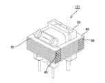
- FIG. 1 is a perspective view of a current transformer according to an embodiment of the present invention.
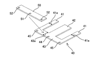
- FIG. 2 is an exploded perspective view of a core component for a current transformer of the present invention.
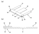
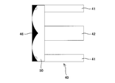
- FIG. 3 is a perspective view (a) and a cross-sectional view (b) of a core component for a current transformer in which an E-type core and an I-type core are integrated by caulking.
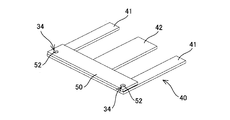
- FIG. 4 is a perspective view of an embodiment without a pilot hole, which is a core component for a current transformer in which an E-type core and an I-type core are integrated by caulking.
- FIG. 1 is a perspective view of a current transformer according to an embodiment of the present invention.
- FIG. 2 is an exploded perspective view of a core component for a current transformer of the present invention.
- FIG. 3 is a perspective view (a) and a cross-sectional view (b) of a core component for a current transformer in which an E-type core and an I-type core are integrated by caul
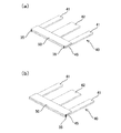
- FIG. 5 is a perspective view of a core component for a current transformer in which an E-type core and an I-type core are integrated by welding, in which (a) is an edge and (b) is a side surface welded. ..
- FIG. 6 is a plan view showing a region where the magnetic flux density is low when the core component for the current transformer is incorporated in the current transformer.
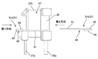
- FIG. 7 is a side view showing a process of inserting a core component for a current transformer into a bobbin around which a primary coil and a secondary coil are wound.
- FIG. 8 is a vertical cross-sectional view showing a process of inserting a core component for a current transformer into the bobbin.
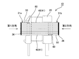
- FIG. 10 shows a step of adjusting a gap formed between a core component for a current transformer inserted and integrated from the first direction and a core component for a current transformer inserted and integrated from the second direction. It is a side view.
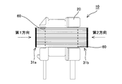
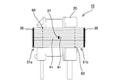
- FIG. 11 shows a state in which the core component for the current transformer inserted and integrated from the first direction and the core component for the current transformer inserted and integrated from the second direction are integrated by spot welding after adjusting the gap. It is a side view which shows.
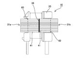
- FIG. 12 is a side view showing an embodiment in which the core component for a current transformer inserted from the first direction and the core component for a current transformer inserted from the second direction are integrated after adjusting the gap.
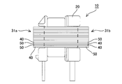
- FIG. 13 is a side view showing an embodiment in which the front and back stacking order is changed when stacking the core components for the current transformer.
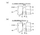
- FIG. 14 is an enlarged view of a butt portion of an E-type core and an I-type core (both manufactured by press punching) facing each other with a gap in between, and FIG. 14A is an enlarged view of shear sections and fracture surfaces abutted against each other.
- An embodiment, (b) shows an embodiment in which a shear section and a fracture surface are butted against each other.
- FIG. 15 is a perspective view showing a manufacturing mode of a current transformer in which a core component for a current transformer inserted from the first direction and a core component for a current transformer inserted from the second direction are each previously blocked and inserted into a bobbin.
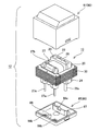
- FIG. 16 is an exploded view of the current transformer module according to the embodiment of the present invention.
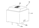
- FIG. 17 is a perspective view of the current transformer module.
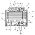
- FIG. 18 is a cross-sectional view of the current transformer module.
- FIG. 19 is a bottom view of the upper case.
- FIG. 20 is a plan view of the lower case.
- FIG. 21 is a circuit diagram of the current transformer output voltage measuring circuit in the embodiment.
- FIG. 22 is a perspective view of the current transformer of Comparative Example 1.
- FIG. 23 is a perspective view of the current transformer of Comparative Example 2.
- FIG. 24 is a perspective view of the current transformer of Comparative Example 3.
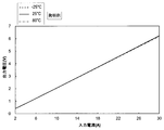
- FIG. 25 is a graph (Example 1) showing the output voltage characteristics of ⁇ 25 ° C., 25 ° C., and 80 ° C. of the invention example.
- FIG. 26 is a graph (Example 2) for comparing the output voltage characteristics of Invention Example, Comparative Example 1 and Comparative Example 2.
- FIG. 27 is a graph (Example 3) showing the output voltage characteristics of Comparative Example 3 at ⁇ 25 ° C., 25 ° C., and 80 ° C.
- core component the current transformer core component 31 (hereinafter referred to as “core component”), the current transformer 10, and the current transformer module 12 according to the embodiment of the present invention will be described with reference to the drawings.
- FIG. 1 is a perspective view of a current transformer 10 according to an embodiment of the present invention.
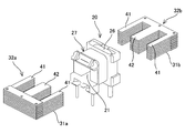
- the current transformer 10 has a common magnetic path of the primary coil 26 and the secondary coil 27 on the resin bobbin 20 around which the primary coil 26 and the secondary coil 27 are wound. It is configured by mounting the core 30 forming the above.
- the primary side coil 26 is a U-shaped winding member
- the secondary side coil 27 is a thin winding member wound around the bobbin 20, and the outer circumference is protected by tape. There is.
- the core 30 is configured by laminating a plurality of core parts 31.
- FIG. 2 is an exploded perspective view of one core component 31 constituting the core 30.
- the core component 31 can be composed of an E-type core 40 and an I-type core 50.
- the E-type core 40 and the I-type core 50 can be obtained by press-punching an electromagnetic steel sheet such as a silicon steel sheet. For example, a thin strip-shaped electromagnetic steel plate can be adopted.
- the E-shaped core 40 includes three substantially rectangular legs 41, 42, 41 extending substantially in parallel and a substantially rectangular connecting portion 43 connecting one ends of these legs 41, 42, 41. It is desirable that the width dimension 43a of the connecting portion 43 is longer than the width dimension 41a of the leg portion 41 in order to suppress the leakage flux. Further, the I-type core 50 can have a substantially rectangular shape having substantially the same size as the connecting portion 43. It is desirable that the E-type core 40 and the I-type core 50 have pilot holes 44 and 51 for positioning. Further, in order to align the I-type core 50 with the E-type core 40 and facilitate stacking, the length-wise dimension of the I-type core 50 is smaller than the longitudinal dimension of the connecting portion 43 of the E-type core 40. It is desirable to reduce the size by 1 mm to 0.3 mm.
- the E-type core 40 and the I-type core 50 form a core component 31 by superimposing the I-type core 50 on the connecting portion 43 of the E-type core 40 and integrating them.
- Examples of the integration include caulking 34 shown in FIGS. 3 and 4, welding 35 shown in FIG. 5, and adhesion (not shown).
- a caulking hole 45 is formed in advance in one of the E-type core 40 or the I-type core 50 and a dowel 52 is formed in the other as shown in FIG. , As shown in FIGS. 3A and 3B, the E-type core 40 and the I-type core 50 may be overlapped and the caulking holes 45 and the dowels 52 may be aligned to perform the caulking 34.
- the caulking hole 45 can be formed at the same time when the E-type core 40 and the I-type core 50 are pressed and punched. When the caulking hole 45 is formed, it is desirable that the caulking hole 45 is formed in the E-shaped core 40 having a large area in order to suppress a decrease in strength or deformation of the core 30.
- FIG. 5 the outer edge of the connecting portion 43 of the E-type core 40 and the outer edge of the I-type core 50 are shown in FIG. 5 (a). Welding may be performed so as to straddle. Further, as shown in FIG. 5B, welding 35 may be performed so as to straddle both ends of the connecting portion 43 of the E-type core 40 and both ends of the I-type core 50. Welding 35 can exemplify laser welding, laser welding, and resistance welding (the same applies to welding according to the following description), but is not limited thereto.
- welding 35 is performed in the region 46 having a low magnetic flux density among the core parts 31, that is, in the corners and the center near the outer edge of the E-type core 40 and the I-type core 50. Is desirable. Since the region 46 is a region where the magnetic flux density is low even in the magnetic path, the influence on the performance can be suppressed even if the magnetic characteristics are slightly deteriorated.
- a plurality of core components 31 formed by integrating the E-type core 40 and the I-type core 50 are prepared (current transformer core component preparation step), and the core component 31 is mounted on the bobbin 20. ..
- the bobbin 20 is wound with a U-shaped primary coil 26 and a secondary coil 27 whose outer circumference is protected by tape 27b, and the bobbin 20 is orthogonal to these coils 26 and 27.
- a hollow portion 21 having a penetrating direction is prepared (bobbin preparation step).
- the core component 31 is laminated by sequentially inserting the central leg portion 42 into the hollow portion 21 of the bobbin 20. Specifically, as shown in the figure, the core parts 31 and 31 are alternately inserted into the hollow portion 21 in the opposite directions.
- the first core component 31 With the I-type core 50 facing upward, the legs 41, 42, 41 of the E-type core 40 facing the bobbin 20 side from the first direction, and the bobbin so that the central leg 42 is inserted into the hollow portion 21.
- the central leg portion 42 is inserted into the hollow portion 21 by approaching 20.
- the I-type core 50 faces downward
- the legs 41, 42, 41 of the E-type core 40 face the bobbin 20 side from the second direction
- the central leg 42 The bobbin 20 is approached so as to be inserted into the hollow portion 21, the central leg portion 42 is inserted into the hollow portion 21, and the legs 41, 42, 41 of the first core component 31 and the second core component 31 are inserted.
- the legs 41, 42, 41 of the above are overlapped.
- the core component inserted from the first direction will be referred to as a first core component 31a
- the core component inserted from the second direction will be referred to as a second core component 31b.
- the first core component 31a and the second core component 31b become the leg portion 41 as shown in FIG. , 42 (42 is not shown) are laminated in a stacked state (lamination step).
- the current transformer 10 can be obtained by this, but in this state, the first core component 31a and the second core component 31b are not fixed or the like, and are still inserted into the hollow portion 21. Therefore, as shown in FIG. 9, the first core parts 31a and the second core parts 31b are integrated with each other by aligning the edges so that the laminated first core parts 31a and the second core parts 31b do not come apart. It is desirable to do (integration step).
- the integration can be, for example, welding as shown by reference numeral 36 in FIG. Welding 36 can be exemplified by laser welding and resistance welding. In addition, it may be integrated by caulking or adhesive. When welding 36 is performed, it is desirable to perform welding in the region 46 having a low magnetic flux density described with reference to FIG.
- the tips of the legs 41, 42, 41 of the first core component 31a and the I-type core of the second core component 31b A gap 60 is formed between the 50 and the inner edge of the 50. Further, a gap 60 is formed between the tips of the legs 41, 42, 41 of the second core component 31b and the inner edge of the I-shaped core 50 of the first core component 31a.
- the gap 60 can be adjusted by pushing the first core component 31a and the second core component 31b from the first direction and the second direction (gap adjustment step).
- the tolerance can be made as small as possible. According to the present invention, the tolerance can be ⁇ 1% or less, preferably ⁇ 0.5% or less in terms of actual value.
- the gap 60 can be 0.1 mm to 0.4 mm, preferably about 0.2 mm.
- the first core component 31a and the second core component 31b are welded 37 at the overlapping positions of the legs 41 and 41 located on the outer side. Integrate by means of etc. (integration step). As a result, the first core component 31a and the second core component 31b are integrated, and it is possible to prevent the gap 60 once adjusted from changing in width. Since the first core component 31a and the second core component 31b are integrated first, the welding 37 for integrating the first core component 31a and the second core component 31b is performed at one or a plurality of locations. Only spot welding is required. Therefore, the welding 37 has almost no effect on the magnetic characteristics of the core parts 31a and 31b.
- the first core component 31a and the second core component 31b can be integrated without using a varnish, an adhesive, or a resin, so that they are not affected by thermal expansion and contraction. Therefore, it is possible to provide a current transformer 10 having excellent temperature characteristics.
- the first core component 31a and the second core component 31b are integrated with each other, and then the gap 60 is adjusted to integrate the first core component 31a and the second core component 31b. ..
- the welding 36 of FIG. 9 may be omitted, and the gap 60 may be adjusted without integrating the first core parts 31a and the second core parts 31b.
- the overlapping positions of the legs 41 and 41 located outside the first core component 31a and the second core component 31b may be line-welded 38 as shown in FIG.
- the manufacturing process of the current transformer 10 can be simplified.
- the first core component 31a and the second core component 31b are welded 37, 38 at the substantially central portion of the leg portion 41 of the E-shaped core 40. Therefore, the length of the linear expansion is suppressed to half, and the first core component 31a and the second core component 31b linearly expand in the same direction starting from the welded portions 37 and 38, so that the gap 60 does not change substantially. Further, since the welded portions 36 and 37 in FIG. 11 and the welded portions 38 in FIG. 12 are formed substantially parallel to the stacking direction of the first core component 31a and the second core component 31b, the lines due to the heat of these welded portions are formed. Expansion does not affect the size of the gap 60.
- all the first core parts 31a are stacked with the I-type core 50 facing upward, and all the second core parts 31b are stacked facing downward.
- the first core part 31a and the first core component 31a As long as the two core parts 31b are paired, the front and back sides may be changed alternately, for each of a plurality of pairs, or even randomly. As a result, it is possible to equalize the variation in thickness due to the burrs 73 and the drool 70 (see FIG. 14) when the E-type core 40 and the I-type core 50 are manufactured by press punching.
- the E-type core 40 and the I-type core 50 are arranged so that the shear sections 71 and 71 and the fracture surfaces 72 and 72 face each other, and the fracture surfaces 72 and 72 are butted against each other. Then, the fracture surfaces 72 and 72 come into contact with each other, but a gap remains between the shear sections 71 and 71. Therefore, the adjustment range of the gap becomes small, and the adjustment range of the output voltage also becomes narrow. Therefore, when the E-type core 40 and the I-type core 50 are butted against each other, as shown in FIG. 14B, the E-type core 40 and the I-type core 50 have a shear section 71 and a fracture surface 72 facing each other. It is desirable to arrange them in such a manner. As a result, the gap 60 can be reduced, so that the adjustment range of the gap 60 can be widened to widen the adjustment range of the output voltage, and the adjustment can be easily performed.
- the first core component 31a and the second core component 31b are inserted into the hollow portion 21 one by one.
- the first core component block 32a and the second core component 31b in which the first core component 31a is laminated in advance and integrated by welding or caulking, are laminated in advance and integrated by welding or caulking.
- the second core component block 32b is created and mounted on the bobbin 20
- the legs 41 and the second core component of the second core component 31b are sandwiched between the legs 41 and 41 of the first core components 31a and 31a.
- the legs 41 of the first core component 31a may be engaged so as to penetrate between the legs 41 and 41 of the 31b and 31b.
- the core parts 31a and 31b do not need to be laminated one by one on the bobbin 20, so that the manufacturing process can be simplified as much as possible.
- the current transformer 10 obtained as described above can be housed in the casing 80 and used as the current transformer module 12.
- 16 is an exploded perspective view of the current transformer 10 and the casing 80 accommodating the current transformer 10
- FIG. 17 is a perspective view of the current transformer 10
- FIG. 18 is a vertical sectional view of the current transformer 10.
- the casing 80 is formed from an upper case 81 and a lower case 85.
- the upper case 81 has an open housing shape on the lower surface for accommodating the core 30 and the bobbin 20
- the lower case 85 has a plate shape on which the bobbin 20 is placed and closes the lower surface of the upper case 81. it can.
- FIG. 19 shows a bottom view of the upper case 81
- FIG. 20 shows a plan view of the lower case 85.
- the lower case 85 is formed with insertion holes 86a and 86b into which the terminal wires 26a and 26a of the primary coil 26 and the terminal wires 27a and 27a of the secondary coil 27 are extended, respectively.
- the current transformer module 12 can be obtained by inserting the terminal wires 26a and 26b into the insertion holes 86a and 86b and fitting the upper case 81 with the bobbin 20 positioned in the lower case 85. The obtained current transformer module 12 is shown in FIG.
- the output voltage characteristics can be measured individually, and the obtained characteristic data can be printed or sealed on the upper case 81 as a data matrix 89 as shown in FIG.
- the data matrix 89 can be read and the characteristic adjustment can be performed on the control based on the corresponding characteristic data. As a result, more accurate output voltage characteristics can be achieved.
- the bobbin 20 has an upper insulating wall 22 and a primary coil 26 provided between the primary coil 26 and the secondary coil 27.
- An upper concave portion 23 is formed between them, while an upper convex portion 83 that fits into the upper concave portion 23 is formed in the upper case 81 as shown in FIGS. 18 and 19.
- the upper convex portion 83 fits into the upper recess 23 to form an insulating wall, and the creepage distance between the insulation of the primary coil 26 and the secondary coil 27 is increased. I try to earn a long time. Further, the bobbin 20 can be positioned on the upper case 81 by fitting the upper convex portion 83 into the upper concave portion 23.
- a recess is formed along the outer shape of the primary coil 26 as a contact portion 82 for suppressing the primary coil 26 from coming off.
- the contact portion 82 prevents the primary coil 26 from floating when the current transformer module 12 is mounted on a printed wiring board or the like.
- the bobbin 20 has a lower recess 25 between the lower insulating wall 24 provided between the primary coil 26 and the secondary coil 27 and the primary coil 26.
- the lower case 85 is formed with a lower convex portion 87 that fits into the lower recess 25.
- the lower convex portion 87 fits into the lower recess 25 and becomes an insulating wall to insulate the primary coil 26 and the secondary coil 27. I am trying to earn a long creepage distance.
- the current transformer 10 and the current transformer module 12 can be downsized by lowering the insulating walls 22 and 24 of the bobbin 20 while ensuring the creepage distance between the primary coil 26 and the secondary coil 27. Further, the bobbin 20 can be positioned on the lower case 85 by fitting the lower convex portion 87 into the lower recess 25.
- the lower case 85 is provided with a step portion 88 that supports the lower surface of the bobbin 20, and when the bobbin 20 comes into contact with the lower case 85, the lower surface of the bobbin 20 is brought into contact with the step portion 88, and the bobbin 20 is the casing 80. It is desirable to hold it without tilting inside.
- the core 30 since the gap 60 is adjusted with reference to the output voltage characteristic, the core 30 has a play in the longitudinal direction of the leg 41 with respect to the bobbin 20 due to the width of the gap 60. It will be held, and may slide in the penetrating direction of the hollow portion 21 to cause play. Therefore, in the current transformer module 12, it is desirable to position the core 30 with respect to the bobbin 20.
- the bobbin 20 is positioned on the casing 80 by fitting the upper concave portion 23 and the upper convex portion 83, and fitting the lower concave portion 25 and the lower convex portion 87. Therefore, if the core 30 can also be positioned with respect to the casing 80, the core 30 and the bobbin 20 can also be positioned relative to each other. Therefore, in the present embodiment, as shown in FIG. 18, a structure capable of positioning the core 30 with respect to the casing 80 is adopted.
- the current transformer 10 was incorporated into the output voltage measuring circuit 90 shown in FIG. 21 to measure the output voltage characteristics.
- the output voltage measuring circuit 90 connects the primary side coil 26 of the current transformer 10 to the AC power supply 92 connected in series with the ammeter 91, while the secondary side coil 27 connects to the voltmeter 94 in parallel with the resistor 93. Connected.
- the current transformer 10 shown in FIG. 1 was adopted.
- the current transformer 100 having only the E-type core 40 omitting the I-type core shown in FIG. 1 of Patent Document 1 is shown in Comparative Example 1 (FIG. 22) and the E-type core shown in FIG. 6 of Patent Document 1.
- a current transformer 101 in which the 40 and the I-type core 50 are integrated with a varnish or the like is shown in Comparative Example 2 (FIG. 23).
- the E-type core 40 is vertically stacked to form a block
- the I-type core 50 is also vertically stacked to block.
- a current transformer 102 in which the block 103 of the E-type core 40 and the block 104 of the I-type core 50 were butted against each other and fixed with a varnish was prepared as Comparative Example 3 (FIG. 24).
- the input current (A) was changed and the output voltage (V) was measured in a temperature atmosphere of ⁇ 25 ° C., 25 ° C., and 80 ° C.
- the results are shown in FIG.
- the current transformer 10 of the present invention has an excellent temperature characteristic because the output voltage is proportional to the input current in each temperature atmosphere.
- the E-type core 40 and the I-type core 50 which have been integrated in advance by caulking or welding, are integrated by insertion welding from the first direction and the second direction to form the current transformer 10, so that the core 30 is integrated.
- varnish, adhesive, resin, etc. which are susceptible to thermal expansion and contraction, are not used for the purpose of conversion, and the influence of thermal expansion and contraction can be reduced as much as possible.
- the output voltage characteristics of the current transformer 10 (FIG. 1) of the invention example, the current transformer 100 (FIG. 22) of the comparative example 1, and the current transformer 101 (FIG. 23) of the comparative example 2 were measured in a temperature atmosphere of 25 ° C. The results are shown in FIG. With reference to FIG. 26, in the invention example, the output voltage with respect to the input current has a substantially linear proportional relationship. However, in Comparative Example 1, the output voltage is lowered on the large current side. Further, in Comparative Example 1, since the tip of the leg of the E-shaped core 40 is open, there is a problem that the leakage flux between the legs becomes large and the magnetic saturation becomes fast. In order to solve this, Comparative Example 1 also needs to increase the size of the core. In Comparative Example 2, it is necessary to fix the E-type core 40 and the I-type core 50 with a varnish, and it can be seen that the output voltage is lowered particularly on the large current side due to their misalignment.
- the output voltage characteristics of the current transformer 102 (FIG. 24) of Comparative Example 3 were measured in the temperature atmospheres of ⁇ 25 ° C., 25 ° C., and 80 ° C. in the same manner as in Example 1. The results are shown in FIG. With reference to FIG. 27, it can be seen that the current transformer 102 of Comparative Example 3 has variations in output voltage characteristics due to temperature changes. This is because the varnish that fixes the core 30 thermally expands and contracts due to the temperature change, the core 30 linearly expands, and the gap between the block 103 of the E-type core 40 and the block 104 of the I-type core 50 changes. Because it was done.
Landscapes
- Engineering & Computer Science (AREA)
- Power Engineering (AREA)
- Manufacturing & Machinery (AREA)
- Chemical & Material Sciences (AREA)
- Composite Materials (AREA)
- Transformers For Measuring Instruments (AREA)
- Manufacturing Cores, Coils, And Magnets (AREA)
- Measuring Instrument Details And Bridges, And Automatic Balancing Devices (AREA)
Abstract
Description
電磁鋼板から形成され、略平行に延びる3本の脚部と、前記脚部の端部を繋ぐ繋ぎ部と、を有するE型コアと、
電磁鋼板から形成され、前記繋ぎ部と略同じ長さのI型コアと、
を具え、
前記E型コアの前記繋ぎ部上に前記I型コアを重ねて一体化している。
貫通した中空部を有し、1次側コイルと2次側コイルを巻線した樹脂製のボビンと、
前記ボビンの前記中空部に、電磁鋼板から形成され、略平行に延びる3本の脚部と、前記脚部の端部を繋ぐ繋ぎ部とを有するE型コアの中央の脚部を交互に逆向きに積層し、積層された前記E型コアの前記繋ぎ部間に電磁鋼板から形成され、前記繋ぎ部と略同じ長さのI型コアが配置されたコアと、
を具える、カレントトランスであって、
前記コアは、請求項1に記載のカレントトランス用コア部品を、前記ボビンの前記中空部に第1方向と前記第1方向に対向する第2方向から交互に差し込んで積層したものである。
前記カレントトランス用コア部品は、前記ボビンの前記中空部に第1方向と前記第1方向に対向する第2方向から交互に且つ表裏を逆向きにして積層したものであり、前記E型コアと対向する前記I型コアは、抜き方向が逆になるように配置されていることが望ましい。
前記E型コアと前記I型コアどうしは、前記剪断面と前記破断面が対向するように配置することができる。
前記ボビンの前記中空部に前記第2方向から差し込まれた前記カレントトランス用コア部品どうしは積層状態にて互いに一体化されている構成とすることができる。
電磁鋼板から形成され略平行に延びる3本の脚部と、前記脚部の端部を繋ぐ繋ぎ部とを有するE型コアと、電磁鋼板から形成され前記繋ぎ部と略同じ長さのI型コアについて、前記E型コアの前記繋ぎ部上に前記I型コアを重ねて一体化したカレントトランス用コア部品を準備するカレントトランス用コア部品準備ステップ、
貫通した中空部を有し、1次側コイルと2次側コイルを巻線した樹脂製のボビンを準備するボビン準備ステップと、
前記カレントトランス用コア部品の前記E型コアの中央の前記脚部を、前記ボビンの前記中空部に第1方向と前記第1方向に対向する第2方向から交互に差し込んで積層する積層ステップ、
前記積層されたカレントトランス用コア部品を一体化する一体化ステップ、
とを含んでいる。
貫通した中空部を有し、1次側コイルと2次側コイルを巻線した樹脂製のボビンを準備するボビン準備ステップと、
前記カレントトランス用コア部品の前記E型コアの中央の前記脚部を、前記ボビンの前記中空部に第1方向と前記第1方向に対向する第2方向から交互に且つ表裏を逆向きにして差し込んで、前記E型コアと対向する前記I型コアは、抜き方向が逆になるように積層する積層ステップ、
を含むことが望ましい。
前記積層されたカレントトランス用コア部品を、前記第1方向及び/又は前記第2方向から押圧して、前記第1方向から差し込まれた前記カレントトランス用コア部品の前記E型コアの前記脚部の先端と、前記第2方向から差し込まれた前記カレントトランス用コア部品の前記I型コアの端縁との間に形成されるギャップ、及び、前記第2方向から差し込まれた前記カレントトランス用コア部品の前記E型コアの脚部の先端と、前記第1方向から差し込まれた前記カレントトランス用コア部品の前記I型コアの端縁との間に形成されるギャップを調整するギャップ調整ステップ、
を含んでいることが望ましい。
上記実施形態では、第1コア部品31a、第2コア部品31bを1枚ずつ中空部21に挿入している。しかしながら、たとえば、図15に示すように、第1コア部品31aを予め積層して溶接やカシメにより一体化した第1コア部品ブロック32a、第2コア部品31bを予め積層して溶接やカシメにより一体化した第2コア部品ブロック32bを夫々作成し、ボビン20に装着する際に、第1コア部品31a,31aの脚部41,41間に第2コア部品31bの脚部41、第2コア部品31b、31bの脚部41,41間に第1コア部品31aの脚部41が侵入するよう噛み合わせてもよい。これにより、コア部品31a,31bはボビン20で1枚ずつ積層する必要はないから製造工程を可及的に簡便化することができる。
11 カレントトランスモジュール
20 ボビン
21 中空部
30 コア
31 コア部品
31a 第1コア部品
31b 第2コア部品
40 E型コア
50 I型コア
60 ギャップ
80 ケーシング
Claims (5)
- 貫通した中空部を有し、1次側コイルと2次側コイルを巻線した樹脂製のボビンと、
前記ボビンの前記中空部に、電磁鋼板から形成され、略平行に延びる3本の脚部と、前記脚部の端部を繋ぐ繋ぎ部とを有するE型コアの中央の脚部を交互に逆向きに積層し、積層された前記E型コアの前記繋ぎ部間に電磁鋼板から形成され、前記繋ぎ部と略同じ長さのI型コアが配置されたコアと、
を具える、カレントトランスであって、
電磁鋼板をプレス抜き加工して形成され、略平行に延びる3本の脚部と、前記脚部の端部を繋ぐ繋ぎ部と、を有するE型コアと、電磁鋼板をプレス抜き加工して形成され、前記繋ぎ部と略同じ長さのI型コアと、を具え、前記E型コアの前記繋ぎ部上に前記I型コアを重ねて一体化した、カレントトランス用コア部品を、前記ボビンの前記中空部に第1方向と前記第1方向に対向する第2方向から交互に差し込んで積層したものであり、
前記カレントトランス用コア部品は、前記ボビンの前記中空部に第1方向と前記第1方向に対向する第2方向から交互に且つ表裏を逆向きにして積層したものであり、前記E型コアと対向する前記I型コアは、抜き方向が逆になるように配置されている、
カレントトランス。 - 前記E型コアと前記I型コアの端面は、プレス抜き加工により、角部が丸みを帯びてなめらかなだれ、剪断により板厚方向に筋状痕が形成された剪断面、材料がむしり取られたごとく凹凸の激しい破断面、端面から抜き方向に飛び出したギザギザ状のバリが形成されており、
前記E型コアと前記I型コアどうしは、前記剪断面と前記破断面が対向するように配置される、
請求項1に記載のカレントトランス。 - 前記ボビンの中空部にて積層された前記カレントトランス用コア部品は、互いに一体化している、
請求項1又は請求項2に記載のカレントトランス。 - 前記ボビンの前記中空部に前記第1方向から差し込まれた前記カレントトランス用コア部品どうしは積層状態にて互いに一体化され、
前記ボビンの前記中空部に前記第2方向から差し込まれた前記カレントトランス用コア部品どうしは積層状態にて互いに一体化されている、
請求項1乃至請求項3の何れかに記載のカレントトランス。 - カレントトランスの製造方法であって、
電磁鋼板をプレス抜き加工して形成され略平行に延びる3本の脚部と、前記脚部の端部を繋ぐ繋ぎ部とを有するE型コアと、電磁鋼板をプレス抜き加工して形成され前記繋ぎ部と略同じ長さのI型コアについて、前記E型コアの前記繋ぎ部上に前記I型コアを重ねて一体化したカレントトランス用コア部品を準備するカレントトランス用コア部品準備ステップ、
貫通した中空部を有し、1次側コイルと2次側コイルを巻線した樹脂製のボビンを準備するボビン準備ステップと、
前記カレントトランス用コア部品の前記E型コアの中央の前記脚部を、前記ボビンの前記中空部に第1方向と前記第1方向に対向する第2方向から交互に且つ表裏を逆向きにして差し込んで、前記E型コアと対向する前記I型コアは、抜き方向が逆になるように積層する積層ステップ、
前記積層されたカレントトランス用コア部品を、前記第1方向及び/又は前記第2方向から押圧して、前記第1方向から差し込まれた前記カレントトランス用コア部品の前記E型コアの前記脚部の先端と、前記第2方向から差し込まれた前記カレントトランス用コア部品の前記I型コアの端縁との間に形成されるギャップ、及び、前記第2方向から差し込まれた前記カレントトランス用コア部品の前記E型コアの脚部の先端と、前記第1方向から差し込まれた前記カレントトランス用コア部品の前記I型コアの端縁との間に形成されるギャップを、出力電圧特性を参照しながら調整するギャップ調整ステップ、
前記積層されたカレントトランス用コア部品を一体化する一体化ステップ、
とを含んでいる、
カレントトランスの製造方法。
Priority Applications (4)
| Application Number | Priority Date | Filing Date | Title |
|---|---|---|---|
| KR1020227002945A KR102815869B1 (ko) | 2019-07-31 | 2020-06-23 | 변류기 및 변류기의 제조 방법 |
| CN202080054871.5A CN114175185B (zh) | 2019-07-31 | 2020-06-23 | 电流互感器和电流互感器的制造方法 |
| US17/630,283 US12334251B2 (en) | 2019-07-31 | 2020-06-23 | Current transformer and method of manufacturing the same |
| EP20847083.1A EP4006929B1 (en) | 2019-07-31 | 2020-06-23 | Current transformer and method for manufacturing current transformer |
Applications Claiming Priority (2)
| Application Number | Priority Date | Filing Date | Title |
|---|---|---|---|
| JP2019-140979 | 2019-07-31 | ||
| JP2019140979A JP6644291B1 (ja) | 2019-07-31 | 2019-07-31 | カレントトランス用コア部品、これを用いたカレントトランス及びカレントトランスの製造方法 |
Publications (1)
| Publication Number | Publication Date |
|---|---|
| WO2021019963A1 true WO2021019963A1 (ja) | 2021-02-04 |
Family
ID=69412170
Family Applications (1)
| Application Number | Title | Priority Date | Filing Date |
|---|---|---|---|
| PCT/JP2020/024549 Ceased WO2021019963A1 (ja) | 2019-07-31 | 2020-06-23 | カレントトランス及びカレントトランスの製造方法 |
Country Status (7)
| Country | Link |
|---|---|
| US (1) | US12334251B2 (ja) |
| EP (1) | EP4006929B1 (ja) |
| JP (1) | JP6644291B1 (ja) |
| KR (1) | KR102815869B1 (ja) |
| CN (1) | CN114175185B (ja) |
| TW (1) | TWI853969B (ja) |
| WO (1) | WO2021019963A1 (ja) |
Families Citing this family (2)
| Publication number | Priority date | Publication date | Assignee | Title |
|---|---|---|---|---|
| JP6679061B1 (ja) * | 2020-02-07 | 2020-04-15 | 株式会社エス・エッチ・ティ | カレントトランスモジュール |
| CN116705469B (zh) * | 2023-08-07 | 2024-01-16 | 季华实验室 | 一种llc变压器装配结构及其装配方法 |
Citations (9)
| Publication number | Priority date | Publication date | Assignee | Title |
|---|---|---|---|---|
| JPS53107817U (ja) * | 1977-02-01 | 1978-08-30 | ||
| JPS53121413U (ja) * | 1977-03-04 | 1978-09-27 | ||
| JPS6318824U (ja) | 1986-07-23 | 1988-02-08 | ||
| JPH0864428A (ja) * | 1994-08-17 | 1996-03-08 | Sanken Electric Co Ltd | 積層鉄心及びその組立方法 |
| JPH08213255A (ja) * | 1995-02-03 | 1996-08-20 | Mitsumi Electric Co Ltd | トランス |
| JPH08250320A (ja) * | 1995-03-10 | 1996-09-27 | Mitsui High Tec Inc | 積層鉄心および積層鉄心の製造方法 |
| JPH11186061A (ja) * | 1997-12-18 | 1999-07-09 | Toshiba Corp | 小型トランス |
| JP2005203445A (ja) * | 2004-01-13 | 2005-07-28 | Canon Inc | 変圧器 |
| JP2018163952A (ja) * | 2017-03-24 | 2018-10-18 | Fdk株式会社 | カレントトランス |
Family Cites Families (16)
| Publication number | Priority date | Publication date | Assignee | Title |
|---|---|---|---|---|
| GB522479A (en) * | 1938-11-14 | 1940-06-19 | John Bentley Hansell | Improvements relating to alternating current voltage regulators |
| US3803479A (en) | 1972-09-18 | 1974-04-09 | Foster Transformer Co | Voltage regulating transformer |
| JPS53121413A (en) | 1977-03-03 | 1978-10-23 | Furukawa Electric Co Ltd:The | Manufacturing unit for crossing type induction radio wire |
| JPS6022559B2 (ja) | 1977-03-03 | 1985-06-03 | パイオニア株式会社 | コ−ン型スピ−カの錦糸線接続方法 |
| DE2920365A1 (de) * | 1979-05-19 | 1980-11-27 | Philberth Karl Dr Phys | Kernblech fuer mantelkerne, insbesondere fuer transformatoren |
| JPS6318824A (ja) | 1986-07-11 | 1988-01-26 | Nippon Telegr & Teleph Corp <Ntt> | 2ピ−ス形携帯無線電話機 |
| US4827237A (en) * | 1988-08-29 | 1989-05-02 | Coils, Inc. | Transformer core assembly |
| US5088186A (en) * | 1990-03-13 | 1992-02-18 | Valentine Engineering, Inc. | Method of making a high efficiency encapsulated power transformer |
| JP3440853B2 (ja) | 1998-11-20 | 2003-08-25 | 松下電器産業株式会社 | トランス |
| JP2002164236A (ja) * | 2000-11-27 | 2002-06-07 | Ngk Spark Plug Co Ltd | 点火コイル及びそれを用いた点火装置 |
| KR20090131144A (ko) * | 2008-06-17 | 2009-12-28 | 윤득상 | 라인 트랜스 |
| TWI371764B (en) | 2009-11-17 | 2012-09-01 | Delta Electronics Inc | Current transformer structure |
| JP5666324B2 (ja) * | 2011-01-21 | 2015-02-12 | 愛三工業株式会社 | 電流センサ |
| CN104576024A (zh) * | 2014-12-19 | 2015-04-29 | 淮安威灵电机制造有限公司 | 变压器铁芯及其制造方法、变压器及其制造方法 |
| CN105990002B (zh) * | 2015-02-25 | 2020-12-04 | 上海稳得新能源科技有限公司 | 立体全对称铁芯三相电抗器 |
| JP2022026403A (ja) * | 2020-07-31 | 2022-02-10 | 大和製罐株式会社 | 缶容器 |
-
2019
- 2019-07-31 JP JP2019140979A patent/JP6644291B1/ja active Active
-
2020
- 2020-06-23 US US17/630,283 patent/US12334251B2/en active Active
- 2020-06-23 KR KR1020227002945A patent/KR102815869B1/ko active Active
- 2020-06-23 CN CN202080054871.5A patent/CN114175185B/zh active Active
- 2020-06-23 WO PCT/JP2020/024549 patent/WO2021019963A1/ja not_active Ceased
- 2020-06-23 EP EP20847083.1A patent/EP4006929B1/en active Active
- 2020-07-06 TW TW109122761A patent/TWI853969B/zh active
Patent Citations (9)
| Publication number | Priority date | Publication date | Assignee | Title |
|---|---|---|---|---|
| JPS53107817U (ja) * | 1977-02-01 | 1978-08-30 | ||
| JPS53121413U (ja) * | 1977-03-04 | 1978-09-27 | ||
| JPS6318824U (ja) | 1986-07-23 | 1988-02-08 | ||
| JPH0864428A (ja) * | 1994-08-17 | 1996-03-08 | Sanken Electric Co Ltd | 積層鉄心及びその組立方法 |
| JPH08213255A (ja) * | 1995-02-03 | 1996-08-20 | Mitsumi Electric Co Ltd | トランス |
| JPH08250320A (ja) * | 1995-03-10 | 1996-09-27 | Mitsui High Tec Inc | 積層鉄心および積層鉄心の製造方法 |
| JPH11186061A (ja) * | 1997-12-18 | 1999-07-09 | Toshiba Corp | 小型トランス |
| JP2005203445A (ja) * | 2004-01-13 | 2005-07-28 | Canon Inc | 変圧器 |
| JP2018163952A (ja) * | 2017-03-24 | 2018-10-18 | Fdk株式会社 | カレントトランス |
Non-Patent Citations (1)
| Title |
|---|
| See also references of EP4006929A4 |
Also Published As
| Publication number | Publication date |
|---|---|
| US20220277892A1 (en) | 2022-09-01 |
| JP6644291B1 (ja) | 2020-02-12 |
| EP4006929A1 (en) | 2022-06-01 |
| CN114175185A (zh) | 2022-03-11 |
| TWI853969B (zh) | 2024-09-01 |
| EP4006929B1 (en) | 2025-12-03 |
| KR20220038358A (ko) | 2022-03-28 |
| TW202109567A (zh) | 2021-03-01 |
| KR102815869B1 (ko) | 2025-05-30 |
| CN114175185B (zh) | 2024-12-10 |
| US12334251B2 (en) | 2025-06-17 |
| EP4006929A4 (en) | 2023-09-06 |
| JP2021027065A (ja) | 2021-02-22 |
Similar Documents
| Publication | Publication Date | Title |
|---|---|---|
| KR100413386B1 (ko) | 고주파 대전류변압기 | |
| KR102174244B1 (ko) | 트랜스포머 및 이를 포함하는 전원공급장치 | |
| WO2018193504A1 (ja) | 平面トランス、レーザダイオード駆動用電源装置及びレーザ加工装置 | |
| KR102815869B1 (ko) | 변류기 및 변류기의 제조 방법 | |
| US20200227200A1 (en) | Coil component, circuit board, and power supply device | |
| KR102731474B1 (ko) | 변류기 모듈 | |
| EP3062319B1 (en) | Transformer for reducing eddy current losses of coil | |
| JP2016129174A (ja) | 変圧器 | |
| KR20170137630A (ko) | 전자 유도기 및 전자 유도기의 제조 방법 | |
| JP3812701B2 (ja) | 零相変流器 | |
| JP2019071358A (ja) | リアクトル | |
| JP2018067660A (ja) | トランス及び電力変換装置 | |
| JP2007035804A (ja) | 電力変換トランス | |
| JP2011103365A (ja) | リアクトル | |
| JP2010192742A (ja) | リアクトル | |
| KR20170065077A (ko) | 철심 및 이를 구비하는 변압기 | |
| JP2020096008A (ja) | 静止誘導機器用ギャップ付鉄心 | |
| JPH07235432A (ja) | 変圧器用コイルボビン | |
| JP2012054380A (ja) | 電磁機械に於ける鉄心と組合せるコイルの製法 | |
| JP2013062410A (ja) | 変圧器の巻鉄心 | |
| KR20000012578U (ko) | 스위칭 트랜스포머의 코어 구조 |
Legal Events
| Date | Code | Title | Description |
|---|---|---|---|
| 121 | Ep: the epo has been informed by wipo that ep was designated in this application |
Ref document number: 20847083 Country of ref document: EP Kind code of ref document: A1 |
|
| NENP | Non-entry into the national phase |
Ref country code: DE |
|
| ENP | Entry into the national phase |
Ref document number: 2020847083 Country of ref document: EP Effective date: 20220228 |
|
| WWG | Wipo information: grant in national office |
Ref document number: 17630283 Country of ref document: US |
|
| WWG | Wipo information: grant in national office |
Ref document number: 2020847083 Country of ref document: EP |