WO2021020470A1 - サクションストレーナ - Google Patents
サクションストレーナ Download PDFInfo
- Publication number
- WO2021020470A1 WO2021020470A1 PCT/JP2020/029141 JP2020029141W WO2021020470A1 WO 2021020470 A1 WO2021020470 A1 WO 2021020470A1 JP 2020029141 W JP2020029141 W JP 2020029141W WO 2021020470 A1 WO2021020470 A1 WO 2021020470A1
- Authority
- WO
- WIPO (PCT)
- Prior art keywords
- air vent
- vent hole
- moving member
- stopper
- suction strainer
- Prior art date
- Legal status (The legal status is an assumption and is not a legal conclusion. Google has not performed a legal analysis and makes no representation as to the accuracy of the status listed.)
- Ceased
Links
Images







Classifications
-
- F—MECHANICAL ENGINEERING; LIGHTING; HEATING; WEAPONS; BLASTING
- F15—FLUID-PRESSURE ACTUATORS; HYDRAULICS OR PNEUMATICS IN GENERAL
- F15B—SYSTEMS ACTING BY MEANS OF FLUIDS IN GENERAL; FLUID-PRESSURE ACTUATORS, e.g. SERVOMOTORS; DETAILS OF FLUID-PRESSURE SYSTEMS, NOT OTHERWISE PROVIDED FOR
- F15B21/00—Common features of fluid actuator systems; Fluid-pressure actuator systems or details thereof, not covered by any other group of this subclass
- F15B21/04—Special measures taken in connection with the properties of the fluid
- F15B21/041—Removal or measurement of solid or liquid contamination, e.g. filtering
-
- B—PERFORMING OPERATIONS; TRANSPORTING
- B01—PHYSICAL OR CHEMICAL PROCESSES OR APPARATUS IN GENERAL
- B01D—SEPARATION
- B01D36/00—Filter circuits or combinations of filters with other separating devices
- B01D36/001—Filters in combination with devices for the removal of gas, air purge systems
-
- B—PERFORMING OPERATIONS; TRANSPORTING
- B01—PHYSICAL OR CHEMICAL PROCESSES OR APPARATUS IN GENERAL
- B01D—SEPARATION
- B01D24/00—Filters comprising loose filtering material, i.e. filtering material without any binder between the individual particles or fibres thereof
-
- B—PERFORMING OPERATIONS; TRANSPORTING
- B01—PHYSICAL OR CHEMICAL PROCESSES OR APPARATUS IN GENERAL
- B01D—SEPARATION
- B01D29/00—Filters with filtering elements stationary during filtration, e.g. pressure or suction filters, not covered by groups B01D24/00 - B01D27/00; Filtering elements therefor
- B01D29/01—Filters with filtering elements stationary during filtration, e.g. pressure or suction filters, not covered by groups B01D24/00 - B01D27/00; Filtering elements therefor with flat filtering elements
- B01D29/05—Filters with filtering elements stationary during filtration, e.g. pressure or suction filters, not covered by groups B01D24/00 - B01D27/00; Filtering elements therefor with flat filtering elements supported
- B01D29/07—Filters with filtering elements stationary during filtration, e.g. pressure or suction filters, not covered by groups B01D24/00 - B01D27/00; Filtering elements therefor with flat filtering elements supported with corrugated, folded or wound filtering sheets
-
- B—PERFORMING OPERATIONS; TRANSPORTING
- B01—PHYSICAL OR CHEMICAL PROCESSES OR APPARATUS IN GENERAL
- B01D—SEPARATION
- B01D29/00—Filters with filtering elements stationary during filtration, e.g. pressure or suction filters, not covered by groups B01D24/00 - B01D27/00; Filtering elements therefor
- B01D29/11—Filters with filtering elements stationary during filtration, e.g. pressure or suction filters, not covered by groups B01D24/00 - B01D27/00; Filtering elements therefor with bag, cage, hose, tube, sleeve or like filtering elements
- B01D29/13—Supported filter elements
- B01D29/15—Supported filter elements arranged for inward flow filtration
- B01D29/21—Supported filter elements arranged for inward flow filtration with corrugated, folded or wound sheets
-
- B—PERFORMING OPERATIONS; TRANSPORTING
- B01—PHYSICAL OR CHEMICAL PROCESSES OR APPARATUS IN GENERAL
- B01D—SEPARATION
- B01D29/00—Filters with filtering elements stationary during filtration, e.g. pressure or suction filters, not covered by groups B01D24/00 - B01D27/00; Filtering elements therefor
- B01D29/11—Filters with filtering elements stationary during filtration, e.g. pressure or suction filters, not covered by groups B01D24/00 - B01D27/00; Filtering elements therefor with bag, cage, hose, tube, sleeve or like filtering elements
- B01D29/31—Self-supporting filtering elements
- B01D29/33—Self-supporting filtering elements arranged for inward flow filtration
- B01D29/333—Self-supporting filtering elements arranged for inward flow filtration with corrugated, folded filtering elements
-
- B—PERFORMING OPERATIONS; TRANSPORTING
- B01—PHYSICAL OR CHEMICAL PROCESSES OR APPARATUS IN GENERAL
- B01D—SEPARATION
- B01D35/00—Filtering devices having features not specifically covered by groups B01D24/00 - B01D33/00, or for applications not specifically covered by groups B01D24/00 - B01D33/00; Auxiliary devices for filtration; Filter housing constructions
- B01D35/02—Filters adapted for location in special places, e.g. pipe-lines, pumps, stop-cocks
- B01D35/027—Filters adapted for location in special places, e.g. pipe-lines, pumps, stop-cocks rigidly mounted in or on tanks or reservoirs
-
- B—PERFORMING OPERATIONS; TRANSPORTING
- B01—PHYSICAL OR CHEMICAL PROCESSES OR APPARATUS IN GENERAL
- B01D—SEPARATION
- B01D35/00—Filtering devices having features not specifically covered by groups B01D24/00 - B01D33/00, or for applications not specifically covered by groups B01D24/00 - B01D33/00; Auxiliary devices for filtration; Filter housing constructions
- B01D35/02—Filters adapted for location in special places, e.g. pipe-lines, pumps, stop-cocks
- B01D35/027—Filters adapted for location in special places, e.g. pipe-lines, pumps, stop-cocks rigidly mounted in or on tanks or reservoirs
- B01D35/0276—Filtering elements with a vertical rotation or symmetry axis mounted on tanks or reservoirs
-
- F—MECHANICAL ENGINEERING; LIGHTING; HEATING; WEAPONS; BLASTING
- F15—FLUID-PRESSURE ACTUATORS; HYDRAULICS OR PNEUMATICS IN GENERAL
- F15B—SYSTEMS ACTING BY MEANS OF FLUIDS IN GENERAL; FLUID-PRESSURE ACTUATORS, e.g. SERVOMOTORS; DETAILS OF FLUID-PRESSURE SYSTEMS, NOT OTHERWISE PROVIDED FOR
- F15B21/00—Common features of fluid actuator systems; Fluid-pressure actuator systems or details thereof, not covered by any other group of this subclass
- F15B21/04—Special measures taken in connection with the properties of the fluid
- F15B21/044—Removal or measurement of undissolved gas, e.g. de-aeration, venting or bleeding
-
- B—PERFORMING OPERATIONS; TRANSPORTING
- B01—PHYSICAL OR CHEMICAL PROCESSES OR APPARATUS IN GENERAL
- B01D—SEPARATION
- B01D2201/00—Details relating to filtering apparatus
- B01D2201/29—Filter cartridge constructions
- B01D2201/291—End caps
-
- B—PERFORMING OPERATIONS; TRANSPORTING
- B01—PHYSICAL OR CHEMICAL PROCESSES OR APPARATUS IN GENERAL
- B01D—SEPARATION
- B01D2201/00—Details relating to filtering apparatus
- B01D2201/34—Seals or gaskets for filtering elements
- B01D2201/347—Radial sealings
-
- F—MECHANICAL ENGINEERING; LIGHTING; HEATING; WEAPONS; BLASTING
- F15—FLUID-PRESSURE ACTUATORS; HYDRAULICS OR PNEUMATICS IN GENERAL
- F15B—SYSTEMS ACTING BY MEANS OF FLUIDS IN GENERAL; FLUID-PRESSURE ACTUATORS, e.g. SERVOMOTORS; DETAILS OF FLUID-PRESSURE SYSTEMS, NOT OTHERWISE PROVIDED FOR
- F15B1/00—Installations or systems with accumulators; Supply reservoir or sump assemblies
- F15B1/26—Supply reservoir or sump assemblies
Definitions
- the present invention relates to a suction strainer.
- the first lid member of the strainer is provided with a valve body having a valve passage having one end opened in the internal space of the strainer element and the other end opening inside the hydraulic oil tank, and the valve passage.
- a strainer device provided with a check valve having a valve body that is arranged so as to be movable in the vertical direction with respect to the valve seat and that abuts on the valve seat by its own weight to close the valve passage. ..
- the present invention has been made in view of such circumstances, and an object of the present invention is to provide a suction strainer capable of removing air bubbles by using an air vent structure having a small size and a simple structure.
- the suction strainer according to the present invention is, for example, a suction strainer provided in a tank in which oil is stored, and has a tubular filter portion formed by bending a thin plate into a pleated shape.
- An upper plate that covers the entire upper end of the filtration portion and is provided so as to be movable between an upper plate in which an air vent hole is formed, a position for closing the air vent hole, and a position for opening the air vent hole. It is characterized by having a moving member.
- an air vent hole is formed in the upper plate covering the entire upper end of the tubular filtration portion formed by bending a thin plate into a pleated shape.
- the moving member is provided so as to be movable between a position where the air vent hole is closed and a position where the air vent hole is opened. This makes it possible to remove air bubbles using a small and simple air vent structure.
- the upper plate is provided with a rod-shaped member provided with a stopper at the upper end portion, the air vent hole is provided around the rod-shaped member in a plan view, and the rod-shaped member is inserted into the moving member.
- It is a plate-shaped member provided with a hole to be formed, and the moving member can move between a lower end position adjacent to the upper plate and closing the air vent hole and an upper end position in contact with the stopper. You may.
- the moving member can be miniaturized and an air vent portion having a simple structure can be obtained.
- a first protrusion and a second protrusion having a circular ring shape in a plan view are formed on the lower surface of the moving member, and the first protrusion is formed in the vicinity of the inner peripheral surface of the moving member.
- the second protrusion may be formed in the vicinity of the outer peripheral surface of the moving member.
- a hinge provided on a first surface substantially orthogonal to the axis of the filtering portion of the upper plate is provided, the air vent hole is provided on the first surface, and the hinge is adjacent to the air vent hole.
- the rotation shaft of the hinge is substantially parallel to the first surface, and the moving member has an end portion provided on the rotation shaft, a position for closing the air vent hole, and the air vent. It may be rotatable to and from the position where the hole is opened. Thereby, when the moving member is in the position of closing the air vent hole, the air vent portion can be prevented from protruding to the upper side of the upper plate.
- the moving member has a plate-shaped plate-shaped portion and a hemispherical spherical portion provided on the plate-shaped portion and projecting downward from the plate-shaped portion, and the spherical portion of the spherical portion.
- the radius is larger than the radius of the air vent hole, and the moving member may close the air vent hole by inserting the tip of the spherical portion into the air vent hole. As a result, the moving member can close the air vent hole while preventing the moving member from coming into close contact with the plate.
- the moving member includes a first stopper provided at the upper end portion, a second stopper provided at the lower end portion, and a rod-shaped member connecting between the first stopper and the second stopper.
- the first stopper and the second stopper may have a diameter larger than the diameter of the air vent hole in a plan view
- the rod-shaped member may have a diameter smaller than the diameter of the air vent hole in a plan view.
- the second stopper and the rod-shaped member may be formed with a handrail along the longitudinal direction.
- the moving member can be easily provided on the upper plate.
- the first stopper has a hemispherical shape or a truncated cone shape, and the first stopper and the air vent hole may come into contact with each other by a line.
- the moving member can close the air vent hole while preventing the moving member from coming into close contact with the plate.
- air bubbles can be removed by using an air vent structure having a small size and a simple structure.
- FIG. 1 It is a figure which shows the outline of the hydraulic oil tank 100 provided in the suction strainer 1 which is one Embodiment of this invention. It is a figure which shows the outline of a suction strainer 1. It is sectional drawing which shows the outline of the air vent part 20. It is sectional drawing which shows the outline of the air vent part 20. It is a figure which shows the outline of a suction strainer 2. It is sectional drawing which shows the outline of the air vent part 20A. It is sectional drawing which shows the outline of the air vent part 20A. It is sectional drawing which shows the outline of the air vent part 20B which concerns on the modification. It is sectional drawing which shows the outline of the air vent part 20B which concerns on the modification.
- FIG. 1 is a diagram showing an outline of a hydraulic oil tank 100 in which a suction strainer 1 according to an embodiment of the present invention is provided.
- a main part of the hydraulic oil tank 100 is seen through.
- the hydraulic oil tank 100 is installed in a work machine (for example, a hydraulic device) (not shown), and is a tank for storing hydraulic oil provided in a hydraulic circuit of hydraulic oil supplied to the hydraulic device. is there. In the hydraulic circuit, the hydraulic oil is introduced into the hydraulic oil tank 100 through the hydraulic device.
- the hydraulic oil tank 100 includes, for example, a box-shaped tank body 101, and the inside of the tank body 101 is hollow. A suction strainer 1 and a return filter 110 are mainly provided inside the tank body 101.
- an inflow port 101a for allowing hydraulic oil to flow into the tank body 101 is formed on the side surface of the tank body 101.
- the hydraulic oil flowing in from the inflow port 101a is guided to the return filter 110.
- the hydraulic oil is filtered by the return filter 110 and stored in the hydraulic oil tank 100.
- openings 101b and 101c used for maintenance of the suction strainer 1 and the return filter 110 are formed at the upper end of the tank body 101.
- a lid 102 is attached to the opening 101b, and a lid 103 is attached to the opening 101c.
- Bolt insertion holes are formed at the peripheral edges of the lids 102 and 103.
- the lids 102 and 103 are fastened to the tank body 101 by screwing the bolt 105 inserted into the bolt insertion hole into the bolt hole (not shown) of the tank body 101.
- an outflow port 101d that allows hydraulic oil in the tank body 101 to flow out to a hydraulic pump (not shown). Is formed.
- a suction pipe 104 connected to a suction port of a hydraulic pump (not shown) is fitted into the outlet 101d from the outside of the tank body 101.
- a suction strainer 1 is provided on the upper side of the outlet 101d (inside the tank body 101) in order to prevent foreign matter from entering the suction pipe 104.
- the hydraulic oil stored in the hydraulic oil tank 100 is sucked by a hydraulic pump (not shown), flows out to the suction pipe 104 via the suction strainer 1, and is supplied to the hydraulic device again.
- the outlet 101d is not limited to the position shown in FIG. 1 as long as it is near the lower end of the tank body 101.
- the outlet 101d may be formed on the bottom surface of the tank body 101.
- a partition plate 101e that divides the space where the suction strainer 1 is provided and the space where the return filter 110 is provided is provided.
- the partition plate 101e is not essential.
- FIG. 2 is a diagram showing an outline of the suction strainer 1 (however, the hatching showing the cross section is omitted).
- the suction strainer 1 mainly has a strainer portion 10, an air vent portion 20, and a rod portion 30 connected to the strainer portion 10.
- the strainer portion 10 is a member having a substantially cylindrical shape, and is placed on the upper side of the outlet 101d (see FIG. 1).
- the strainer unit 10 mainly has a filtration unit 11, an inner cylinder 12, and plates 15 and 16.
- the inner cylinder 12 is a substantially hollow cylindrical member having openings at both ends, and is formed by using a material having high corrosion resistance (for example, stainless steel or resin).
- the inner cylinder 12 is formed with holes through which hydraulic oil passes in substantially the entire area.
- a filtration unit 11 is provided on the outside of the inner cylinder 12.
- the filtration unit 11 has a substantially cylindrical shape having a thickness in the radial direction.
- the height of the filtration unit 11 is substantially the same as the height of the inner cylinder 12.
- the filtration unit 11 is formed by bending a sheet-shaped thin plate having holes formed in substantially the entire area into a pleated shape, connecting both ends of the bent thin plate, and rolling them into a cylindrical shape.
- the filtration unit 11 is formed of a wire mesh made of fine metal (for example, stainless steel) in which fine wires are woven into a mesh shape, but synthetic resin, paper, or the like is used. Filter paper may be used.
- the filtration unit 11 is for filtering the hydraulic oil.
- a plate 15 is provided at one end of the filtration unit 11 and the inner cylinder 12, and a plate 16 is provided at the other end.
- the plate 15 and the plate 16 are members having a substantially disk shape or a bottomed substantially cylindrical shape, and are formed of resin or metal.
- the plate 15 and the plate 16 are provided so as to cover the ends (openings) of the filtration unit 11 and the inner cylinder 12. In other words, the plate 15 and the plate 16 sandwich the filtration unit 11 and the inner cylinder 12.
- the plate 15 covers the entire upper end of the filtration unit 11 and the inner cylinder 12, and has a surface 15a substantially orthogonal to the axis ax of the filtration unit 11.
- An air vent hole 15b is formed on the surface 15a.
- a plurality of air vent holes 15b are provided around the rod-shaped member 21 (detailed later) in a plan view (viewed from the z direction).
- a plurality of air vent holes 15b are provided along a circle C centered on the central axis ax2 of the rod-shaped member 21 in a plan view. The diameter of this circle C is larger than the diameter of the rod-shaped member 21.
- the plate 15 is provided with a rod-shaped member 21 (detailed later).
- the rod-shaped member 21 and the moving member 22 are air vents 20.
- the air vent 20 will be described in detail later.
- the plate 16 is formed with a cylindrical fitting portion 16a that covers the entire lower end of the filtration portion 11 and the inner cylinder 12 and is externally fitted to the outlet 101d.
- the seal member 17 provided on the inner peripheral surface of the fitting portion 16a prevents hydraulic oil from entering the strainer portion 10 from between the plate 16 and the outlet 101d.
- the rod portion 30 mainly has a rod 31 and a mounting portion 32.
- the rod 31 is arranged in a posture extending upward from the strainer portion 10.
- An attachment portion 32 to be attached to an attachment portion (not shown) formed on the back surface of the lid 103 is provided at the upper end portion of the rod 31.
- a spring (not shown) is provided inside the mounting portion 32 with the total length shortened.
- the spring urges the rod 31, that is, the strainer portion 10 downward (in the ⁇ z direction) in a state where the suction strainer 1 is provided inside the tank body 101.
- the suction strainer 1 By removing the lid 103 from the tank body 101 and pulling the upper end of the rod 31, the suction strainer 1 can be pulled out from the tank body 101 during maintenance or the like.
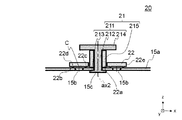
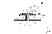
- FIG. 3 and 4 are cross-sectional views showing an outline of the air vent portion 20.
- FIG. 3 shows a case where the moving member 22 is located at the lower end position
- FIG. 4 shows a case where the moving member 22 is located at the upper end position.
- the air vent portion 20 mainly has a rod-shaped member 21 and a moving member 22.
- the rod-shaped member 21 is a member fixed to the surface 15a of the plate 15, and mainly has a metal main body portion 211 and a resin guide portion 215.
- the rod-shaped portion 212 penetrates the hole 15c formed in the surface 15a, and the stopper 213 provided at the lower end portion of the rod-shaped portion 212 is fixed to the back surface of the surface 15a by welding or the like, whereby the plate 15 It is provided in.
- a guide portion 215 is provided around the rod-shaped portion 212.
- the moving member 22 moves along the outer peripheral surface of the guide portion 215.
- a stopper 214 for stopping the movement of the moving member 22 is provided at the upper end of the rod-shaped portion 212.
- the diameter of the stopper 214 is larger than the diameter of the main body 211 and the guide 215.
- the moving member 22 is a plate-shaped member provided with a hole 22a into which the rod-shaped portion 212 is inserted.
- the moving member 22 is formed by using a material (which may be metal or resin) having a density equal to or higher than that of the hydraulic oil.
- the inner diameter of the moving member 22 is smaller than the diameter of the circle C, and the outer diameter of the moving member 22 is larger than the diameter of the circle C.
- the moving member 22 is provided between the surface 15a and the stopper 214, and can move in the vertical direction (z direction) between the position where the air vent hole 15b is closed and the position where the air vent hole 15b is opened.
- Projections 22c and 22d are provided on the lower surface 22b of the moving member 22.
- the protrusions 22c and 22d have a substantially annular shape in a plan view, and prevent the surface 22b from coming into close contact with the surface 15a.
- the protrusion 22c is formed in the vicinity of the inner peripheral surface (that is, the hole 22a) of the moving member 22, and the protrusion 22d is formed in the vicinity of the outer peripheral surface 22e of the moving member 22. Further, in the cross-sectional view as shown in FIG. 3, the air vent hole 15b is located between the protrusion 22c and the protrusion 22d. Therefore, when the protrusions 22c and 22d come into contact with the surface 15a, the moving member 22 covers the air vent hole 15b.
- the moving member 22 closes the air vent hole 15b.
- the air vent hole 15b opens.
- the suction strainer 1 is attached to the tank body 101 in which the hydraulic oil is stored.
- the rod 31 is held so that the mounting portion 32 is located upward (+ z direction), and the suction strainer 1 is pushed downward ( ⁇ z direction).
- the suction strainer 1 Since the upper end of the strainer portion 10 is covered with the plate 15, when the suction strainer 1 is attached to the inside of the tank body 101, air collects inside the inner cylinder 12, that is, on the lower side of the plate 15. The air collected on the lower side of the plate 15 pushes up the moving member 22 in the + z direction through the air vent hole 15b, and as a result, the air vent hole 15b is opened, and the air collected on the lower side of the plate 15 is discharged from the inside of the strainer portion 10 to the tank. It is released to the outside of the main body 101. As a result, the suction strainer 1 is set in the tank body 101, and the function of the suction strainer 1 can be exhibited.
- the air accumulated inside the strainer portion 10, that is, under the plate 15, can be discharged from the inside of the strainer portion 10 to the tank body 101.
- the moving member 22 can be miniaturized to form an air vent portion 20 having a simple structure in which the plate-shaped moving member 22 is moved along the rod-shaped member 21.
- the moving member 22 is moved in the vertical direction to open and close the air vent hole 15b, but the form of opening and closing the air vent hole is not limited to this.
- the second embodiment of the present invention is a form in which a plate-shaped moving member is rotated to open and close an air vent hole.
- the suction strainer 2 according to the second embodiment will be described.
- the same parts as those in the first embodiment are designated by the same reference numerals, and the description thereof will be omitted.
- FIG. 5 is a diagram showing an outline of the suction strainer 2 (however, the hatching showing the cross section is omitted).
- the suction strainer 2 mainly has a strainer portion 10A, an air vent portion 20A, and a rod portion 30 connected to the strainer portion 10A.
- the strainer unit 10A mainly has a filtration unit 11, an inner cylinder 12, and plates 15A and 16.
- the air vent portion 20A mainly has a hinge 23 and a moving member 24.
- the plate 15A has a surface 15a, and an air vent hole 15d is formed in the surface 15a.
- the air vent hole 15d is provided in the vicinity of the rod 31 in a plan view (when viewed from the z direction), but the position of the air vent hole 15d is not limited to this.
- FIG. 6 and 7 are cross-sectional views showing an outline of the air vent portion 20A.
- FIG. 6 shows a case where the moving member 24 is arranged at a position covering the air vent hole 15d
- FIG. 7 shows a case where the moving member 24 is arranged at a position where the air vent hole is opened.
- the hinge 23 is provided at a position adjacent to the air vent hole 15d on the surface 15a, and has a base portion 231 fixed to the surface 15a and a rotation shaft 232 provided on the base portion 231.
- the rotation shaft 232 is substantially parallel to the surface 15a, and is substantially along the horizontal direction when the suction strainer 2 is provided inside the tank 100.
- the moving member 24 is formed by using a material (which may be metal or resin) having a density equal to or higher than that of the hydraulic oil.
- the moving member 24 is a substantially plate-shaped member, and an end portion 24a is provided on the rotating shaft 232. As a result, the moving member 24 can rotate about the rotation shaft 232.
- the shape of the moving member 24 in a plan view may be a substantially circular shape or a substantially rectangular shape.
- a protrusion 24b is provided on the lower surface 24c of the moving member 24.
- the protrusion 24b has an annular shape in a plan view and has a substantially triangular or semicircular cross-sectional shape. Therefore, the protrusion 24b prevents the surface 24c and the surface 15a from coming into close contact with each other.
- the moving member 24 When the moving member 24 is pushed up through the air vent hole 15d by the air accumulated on the lower side of the plate 15, the moving member 24 rotates about the rotation shaft 232 (see the arrow in FIG. 6), and FIG. It moves from the position where the air vent hole 15d shown is closed to the position where the air vent hole 15d shown in FIG. 7 is opened. As a result, the air vent hole 15d is opened, and the air accumulated under the plate 15 is discharged to the outside of the strainer portion 10.
- the moving member 24 moves the moving member 24 around the rotation shaft 232 by the force sucked by the hydraulic pump (not shown). (See the arrow in FIG. 7), and the moving member 24 covers the air vent hole 15d. As a result, the hydraulic oil from which the bubbles have not been removed does not flow into the inner cylinder 12.
- the air accumulated inside the strainer portion 10, that is, under the plate 15, can be discharged from the inside of the strainer portion 10 to the outside of the tank body 101. Further, by rotating the plate-shaped moving member 24 around the rotating shaft 232, the air bleeding portion 20A does not protrude above the plate 15 when the moving member 24 is in the position of closing the air bleeding hole 15d. Can be done. Further, the air vent portion 20A can be made compact and simple.
- the plate-shaped moving member 24 is rotated around the rotating shaft 232, but the shape of the moving member is not limited to this.
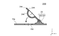
- 8 and 9 are cross-sectional views showing an outline of the air vent portion 20B according to the modified example.
- the air vent portion 20B mainly has a hinge 23 and a moving member 24A.
- FIG. 8 shows a case where the moving member 24A is arranged at a position covering the air vent hole 15d
- FIG. 9 shows a case where the moving member 24A is arranged at a position where the air vent hole is opened.
- the moving member 24A has a substantially plate-shaped plate-shaped portion 24d, and an end portion 24a of the plate-shaped portion 24d is provided on the rotation shaft 232. As a result, the moving member 24A can rotate about the rotation shaft 232.
- the plate-shaped portion 24d has a spherical portion 24e protruding downward from the plate-shaped portion 24d.
- the spherical portion 24e is formed in a substantially hemispherical shape in which the radius r2 is larger than the radius r1 of the air vent hole 15d.
- the moving member 24A When the moving member 24A is pushed up by the compressive force of the air accumulated on the lower side of the plate 15, the moving member 24A rotates about the rotation shaft 232 (see the arrow in FIG. 8), and the air vent hole 15d shown in FIG. It moves from the position of closing the air to the position of opening the air vent hole 15d shown in FIG. As a result, the air vent hole 15d is opened, and the air accumulated under the plate 15 is discharged to the outside of the strainer portion 10.
- the moving member 24A moves the moving member 24A around the rotation shaft 232 by the force sucked by the hydraulic pump (not shown). (See the arrow in FIG. 9), the moving member 24A covers the air vent hole 15d. As a result, the hydraulic oil from which the bubbles have not been removed does not flow into the inner cylinder 12.
- the moving member 22 is moved in the vertical direction along the rod-shaped member 21 to open and close the air vent hole 15b, but the form of opening and closing the air vent hole is not limited to this.
- the third embodiment of the present invention is a mode in which a moving member provided on the plate is moved to open and close the air vent hole.
- the suction strainer 3 according to the third embodiment will be described.
- the same parts as those in the first embodiment are designated by the same reference numerals, and the description thereof will be omitted.
- FIG. 10 is a diagram showing an outline of the suction strainer 3 (however, the hatching showing the cross section is omitted).
- the suction strainer 3 mainly has a strainer portion 10B, an air vent portion 20C, and a rod portion 30 connected to the strainer portion 10B.
- the strainer unit 10B mainly has a filtration unit 11, an inner cylinder 12, and plates 15B and 16.
- the air vent portion 20C has a moving member 25.
- the plate 15A has a surface 15a, and an air vent hole 15e is formed in the surface 15a.
- the air vent hole 15e is provided in the vicinity of the rod 31 in a plan view (when viewed from the z direction), but the position of the air vent hole 15e is not limited to this.
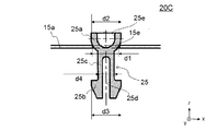
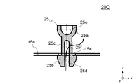
- FIG. 11 and 12 are cross-sectional views showing an outline of the air vent portion 20C.
- FIG. 11 shows a case where the moving member 25 is arranged at a position covering the air vent hole 15e
- FIG. 12 shows a case where the moving member 25 is arranged at a position where the air vent hole 15e is opened.
- the moving member 25 is formed by using a material (which may be metal or resin) having a density equal to or higher than that of the hydraulic oil.
- the moving member 25 has a rod shape as a whole, and connects between the first stopper 25a provided at the upper end portion, the second stopper 25b provided at the lower end portion, and the first stopper 25a and the second stopper 25b. It has a rod-shaped member 25c and.
- the first stopper 25a has a substantially hemispherical shape (lower half of a substantially circular class) that protrudes downward. Since the first stopper 25a and the air vent hole 15e come into contact with each other by a line, it is possible to prevent the first stopper 25a from coming into close contact with the surface 15a.
- the shape of the first stopper 25a is not limited to this, and may be, for example, a substantially spherical shape.
- the diameter d4 of the rod-shaped member 25c is smaller than the diameter d1 of the air vent hole 15e.
- the diameter d2 of the first stopper 25a and the diameter d3 of the second stopper 25b are larger than the diameter d1 of the air vent hole 15e. Therefore, the moving member 25 moves in the vertical direction (z direction) inside the air vent hole 15e, and the moving member 25 is prevented from coming out of the air vent hole 15e by the first stopper 25a and the second stopper 25b.
- the second stopper 25b and the rod-shaped member 25c are formed with a handrail 25d along the longitudinal direction. Therefore, the second stopper 25b and the rod-shaped member 25c can be deformed in a direction in which the diameter becomes smaller, and the moving member 25 is provided on the surface 15a by pushing the moving member 25 into the air vent hole 15e from above (+ z side). ..
- the moving member 25 is pushed up (+ z direction) by the air accumulated on the lower side of the plate 15. As a result, the moving member 25 shown in FIG. 11 moves from the position where the air vent hole 15e is closed to the position where the air vent hole 15e shown in FIG. 12 is opened.
- the rod-shaped member 25c is provided with a hole 25f along the radial direction, and the air accumulated under the plate 15 is discharged to the outside of the strainer portion 10 through the air vent hole 15e, the slit 25d, and the hole 25f. (See arrow in FIG. 12).
- the air accumulated inside the strainer portion 10, that is, under the plate 15, can be discharged from the inside of the strainer portion 10 to the outside of the tank body 101. Further, since the air bleeding portion 20C is composed of only the moving member 25, a compact and simple air bleeding structure can be obtained.
- FIG. 13 and 14 are cross-sectional views showing an outline of the air vent portion 20D according to the modified example.
- the air vent portion 20D has a moving member 26.
- FIG. 13 shows a case where the moving member 26 is arranged at a position covering the air vent hole 15e
- FIG. 14 shows a case where the moving member 26 is arranged at a position where the air vent hole 15e is opened.
- the moving member 26 has a rod shape as a whole, and connects between the first stopper 26a provided at the upper end portion, the second stopper 26b provided at the lower end portion, and the first stopper 26a and the second stopper 26b. It has a rod-shaped member 26c and.
- the second stopper 26b and the rod-shaped member 26c are formed with a handrail 26d along the longitudinal direction so that the moving member 26 can be pushed into the air vent hole 15e from above (+ z side). Since the second stopper 26b, the rod-shaped member 26c, and the grind 26d are the same as the second stopper 25b, the rod-shaped member 25c, and the grind 25d, the description thereof will be omitted.
- the first stopper 26a has a substantially plate shape, and its diameter d5 is larger than the diameter d1 of the air vent hole 15e. Therefore, the moving member 26 moves in the vertical direction (z direction) inside the air vent hole 15e, and the moving member 26 is prevented from coming out of the air vent hole 15e by the first stopper 26a and the second stopper 26b.
- the moving member 26 When the moving member 26 is pushed up through the air vent hole 15e by the air accumulated on the lower side of the plate 15, the moving member 26 opens the air vent hole 15e shown in FIG. 14 from the position where the air vent hole 15e shown in FIG. 13 is closed. Move to the position to make.
- the rod-shaped member 26c is provided with a hole 26f along the radial direction, and the air accumulated under the plate 15 is discharged to the outside of the strainer portion 10 through the air vent hole 15e, the slit 26d, and the hole 26f. (See arrow in FIG. 14).
- a protrusion may be provided on the lower surface (-z side) of the first stopper 26a. Like the protrusion 24b, this protrusion has a substantially annular shape in a plan view, and has a substantially triangular or semicircular cross-sectional shape. As a result, the first stopper 26a and the surface 15a can be prevented from coming into close contact with each other.
- FIG. 15 and 16 are cross-sectional views showing an outline of the air vent portion 20E according to another modified example.
- the air vent portion 20E has a moving member 27.
- FIG. 15 shows a case where the moving member 27 is arranged at a position covering the air vent hole 15e
- FIG. 16 shows a case where the moving member 27 is arranged at a position where the air vent hole 15e is opened.
- the moving member 27 has a rod shape as a whole, and connects between the first stopper 27a provided at the upper end portion, the second stopper 27b provided at the lower end portion, and the first stopper 27a and the second stopper 27b. It has a rod-shaped member 27c and.
- the second stopper 27b and the rod-shaped member 27c are formed with a handrail 27d along the longitudinal direction so that the moving member 27 can be pushed into the air vent hole 15e from above (+ z side). Since the second stopper 27b, the rod-shaped member 27c, and the grind 27d are the same as the second stopper 25b, the rod-shaped member 25c, and the grind 25d, the description thereof will be omitted.
- the first stopper 27a has a substantially truncated cone shape, with the bottom surface (large circle) facing the upper side (+ z side) and the upper surface (small surface) facing the lower side (-z side).
- the diameter d6 of the bottom surface is larger than the diameter d1 of the air vent hole 15e.
- the upper surface of the first stopper 27a is connected to the rod-shaped member 27c, and its diameter d4 is smaller than the diameter d1 of the air vent hole 15e. Therefore, the moving member 27 moves in the vertical direction (z direction) inside the air vent hole 15e, and the moving member 27 is prevented from coming out of the air vent hole 15e by the first stopper 27a and the second stopper 27b.
- the moving member 27 When the moving member 27 is pushed up by the air accumulated on the lower side of the plate 15, the moving member 26 moves from the position where the air vent hole 15e shown in FIG. 15 is closed to the position where the air vent hole 15e shown in FIG. 16 is opened.
- the rod-shaped member 27c is provided with a hole 27f along the radial direction, and the air accumulated under the plate 15 is discharged to the outside of the strainer portion 10 through the air vent hole 15e, the slit 27d, and the hole 27f. (See arrow in FIG. 16).
- “abbreviation” is a concept that includes not only the case of being exactly the same but also an error or deformation to the extent that the identity is not lost.
- substantially orthogonal is not limited to the case of being strictly orthogonal, and is a concept including an error of, for example, several degrees.
- the case of simply expressing orthogonality, parallelism, matching, tubular shape, etc. not only the case of strictly orthogonality, parallelism, matching, etc., but also the case of substantially parallel, substantially orthogonal, substantially matching, substantially tubular shape, etc. Including.
- the "neighborhood” means to include a region in a certain range (which can be arbitrarily determined) near the reference position.
- a certain range which can be arbitrarily determined
- near the edge it is a concept indicating that it is a region of a certain range near the edge and may or may not include the edge.
Landscapes
- Chemical & Material Sciences (AREA)
- Engineering & Computer Science (AREA)
- Chemical Kinetics & Catalysis (AREA)
- Analytical Chemistry (AREA)
- Physics & Mathematics (AREA)
- Fluid Mechanics (AREA)
- Mechanical Engineering (AREA)
- General Engineering & Computer Science (AREA)
- Supply Devices, Intensifiers, Converters, And Telemotors (AREA)
- Filtration Of Liquid (AREA)
Abstract
小型で簡単な構成の空気抜き構造を用いて気泡を除去することができる。 薄板をプリーツ状に折り曲げて形成された略筒状の濾過部の上端全面を覆う上プレートには、空気抜き孔が形成されている。移動部材は、空気抜き孔を塞ぐ位置と、空気抜き孔を開口させる位置との間で移動可能に設けられている。
Description
本発明は、サクションストレーナに関する。
特許文献1には、ストレーナの第一蓋部材に、一端がストレーナエレメントの内部空間に開口するとともに、他端が作動油タンクの内部に開口する弁通路を有した弁本体と、弁通路に設けた弁座に対して上下方向に移動可能に配設し、自重で弁座に当接して弁通路を閉状態とする弁体と、を有するチェック弁が設けられたストレーナ装置が開示されている。
しかしながら、特許文献1に記載の発明では、弁通路を有した弁本体を第一蓋部材に設ける必要があり、チェック弁が大型化するという問題がある。
本発明はこのような事情に鑑みてなされたもので、小型で簡単な構成の空気抜き構造を用いて気泡を除去することができるサクションストレーナを提供することを目的とする。
上記課題を解決するために、本発明に係るサクションストレーナは、例えば、油が貯留されるタンク内に設けられるサクションストレーナであって、薄板をプリーツ状に折り曲げて形成された筒状の濾過部と、前記濾過部の上端全面を覆う上プレートであって、空気抜き孔が形成された上プレートと、前記空気抜き孔を塞ぐ位置と、前記空気抜き孔を開口させる位置との間で移動可能に設けられた移動部材と、を備えたことを特徴とする。
本発明に係るサクションストレーナによれば、薄板をプリーツ状に折り曲げて形成された筒状の濾過部の上端全面を覆う上プレートには、空気抜き孔が形成されている。移動部材は、空気抜き孔を塞ぐ位置と、空気抜き孔を開口させる位置との間で移動可能に設けられている。これにより、小型で簡単な構成の空気抜き構造を用いて気泡を除去することができる。
ここで、前記上プレートには、上端部にストッパが設けられた棒状部材が設けられ、前記空気抜き孔は、平面視において前記棒状部材の周囲に設けられ、前記移動部材は、前記棒状部材が挿入される孔が設けられた板状の部材であり、前記移動部材は、前記上プレートに隣接して前記空気抜き孔を塞ぐ下端位置と、前記ストッパと当接する上端位置との間で移動可能であってもよい。これにより、移動部材を小型化し、簡単な構成の空気抜き部とすることができる。
ここで、前記移動部材の下面には、平面視円環形状の第1の突起と第2の突起とが形成されており、前記第1の突起は前記移動部材の内周面の近傍に形成され、前記第2の突起は前記移動部材の外周面の近傍に形成されていてもよい。これにより、移動部材とプレートとの密着を防ぎつつ、移動部材が空気抜き孔を塞ぐことができる。
ここで、前記上プレートの前記濾過部の軸と略直交する第1面に設けられたヒンジを備え、前記空気抜き孔は、前記第1面に設けられ、前記ヒンジは、前記空気抜き孔に隣接して設けられ、前記ヒンジの回動軸は、前記第1面と略平行であり、前記移動部材は、端部が前記回動軸に設けられており、前記空気抜き孔を塞ぐ位置と、前記空気抜き孔を開口させる位置との間で回動可能であってもよい。これにより、移動部材が空気抜き孔を塞ぐ位置にあるときに、上プレートの上側に空気抜き部が突出しないようにすることができる。
ここで、前記移動部材は、板状の板状部と、前記板状部に設けられており、前記板状部から下向きに突出する半球状の球状部と、を有し、前記球状部の半径は、前記空気抜き孔の半径より大きく、前記球状部の先端が前記空気抜き孔に挿入されることで、前記移動部材が前記空気抜き孔を塞いでもよい。これにより、移動部材とプレートとの密着を防ぎつつ、移動部材が空気抜き孔を塞ぐことができる。
ここで、前記移動部材は、上端部に設けられた第1ストッパと、下端部に設けられた第2ストッパと、前記第1ストッパと前記第2ストッパとの間を連結する棒状部材と、を有し、前記第1ストッパ及び前記第2ストッパは、平面視において直径が前記空気抜き孔の直径より大きく、前記棒状部材は、平面視において直径が前記空気抜き孔の直径より小さくてもよい。このように、空気抜き部を移動部材のみで構成することで、小型で簡単な構成の空気抜き構造とすることができる。
ここで、前記第2ストッパ及び前記棒状部材には、長手方向に沿ってすり割りが形成されていてもよい。これにより、上プレートに移動部材を容易に設けることができる。
ここで、前記第1ストッパは、半球形状又は円錐台形状であり、前記第1ストッパと前記空気抜き孔とが線で接触してもよい。これにより、移動部材とプレートとの密着を防ぎつつ、移動部材が空気抜き孔を塞ぐことができる。
本発明によれば、小型で簡単な構成の空気抜き構造を用いて気泡を除去することができる。
以下、本発明の実施形態を、図面を参照して詳細に説明する。
<第1の実施の形態>
図1は、本発明の一実施形態であるサクションストレーナ1が内部に設けられた作動油タンク100の概略を示す図である。図1では、作動油タンク100の要部を透視して図示している。
<第1の実施の形態>
図1は、本発明の一実施形態であるサクションストレーナ1が内部に設けられた作動油タンク100の概略を示す図である。図1では、作動油タンク100の要部を透視して図示している。
作動油タンク100は、図示しない作業機械(例えば、油圧装置)に設置されるものであり、この油圧装置へ供給する作動油の油圧回路内に設けられた、作動油を貯留するためのタンクである。油圧回路において、作動油は、油圧装置を通って作動油タンク100へ導入される。作動油タンク100は、例えば箱形のタンク本体101を備えており、このタンク本体101はその内部が空洞となっている。タンク本体101の内側には、主として、サクションストレーナ1と、リターンフィルタ110と、が設けられる。
タンク本体101の側面には、作動油をタンク本体101の内部へ流入させる流入口101aが形成される。流入口101aから流入した作動油は、リターンフィルタ110に導かれる。作動油は、リターンフィルタ110により濾過されて、作動油タンク100内に貯留される。
また、タンク本体101の上端部には、サクションストレーナ1やリターンフィルタ110のメンテナンス等に利用する開口部101b、101cが形成される。開口部101bには、蓋体102が取り付けられ、開口部101cには、蓋体103が取り付けられる。
蓋体102、103の周縁部には、ボルト挿通孔が形成される。ボルト挿通孔に挿通されたボルト105をタンク本体101のボルト孔(図示せず)に螺合することにより、蓋体102、103はタンク本体101に締結される。
タンク本体101の下端部近傍(本実施の形態では、タンク本体101の側面の、底面に近い位置)には、タンク本体101内の作動油を油圧ポンプ(図示せず)へ流出させる流出口101dが形成される。流出口101dには、タンク本体101の外側から、油圧ポンプ(図示せず)の吸い込みポートへ繋がるサクションパイプ104が嵌挿されている。
流出口101dの上側(タンク本体101の内側)には、サクションパイプ104への異物の進入を防止するため、サクションストレーナ1が設けられる。作動油タンク100内に貯留された作動油は、油圧ポンプ(図示せず)に吸引されて、サクションストレーナ1を介してサクションパイプ104へ流出し、再度油圧装置へ供給される。
なお、流出口101dは、タンク本体101の下端部近傍であれば、図1に示す位置に限定されない。例えば、流出口101dをタンク本体101の底面に形成してもよい。
タンク本体101の底面には、サクションストレーナ1が設けられる空間と、リターンフィルタ110が設けられる空間と、を分割する仕切板101eが設けられる。なお、仕切板101eは必須ではない。
図2は、サクションストレーナ1の概略を示す図である(ただし、断面を示すハッチングを省略している)。サクションストレーナ1は、主として、ストレーナ部10と、空気抜き部20と、ストレーナ部10に接続されるロッド部30とを有する。
ストレーナ部10は、略円筒形状の部材であり、流出口101dの上側に載置される(図1参照)。
図2に示すように、ストレーナ部10は、主として、濾過部11と、内筒12と、プレート15、16と、を有する。
内筒12は、両端に開口を有する略中空円筒形状の部材であり、耐腐食性の高い材料(例えば、ステンレスや樹脂)を用いて形成される。内筒12には、略全域に作動油が通過する孔が形成されている。
内筒12の外側には、濾過部11が設けられる。濾過部11は、径方向に厚みを有する略円筒形状である。濾過部11の高さは、内筒12の高さと略同じである。濾過部11は、略全域に孔が形成されたシート状の薄板をプリーツ状に折り曲げて、折り曲げた薄板の両端を連結して円筒状に丸めることによって形成される。なお、本実施の形態では、濾過部11は、細線がメッシュ状に編みこまれた目の細かな金属(例えば、ステンレス)製の金網により形成されているが、合成樹脂や紙等を用いたろ紙を用いてもよい。濾過部11は作動油を濾過するためのものである。
濾過部11及び内筒12の一方の端にはプレート15が設けられ、他方の端にはプレート16が設けられる。プレート15及びプレート16は、略円板状又は有底略円筒形状の部材であり、樹脂又は金属を用いて形成される。
プレート15及びプレート16は、濾過部11及び内筒12の端(開口)を覆うように設けられる。言い換えれば、プレート15及びプレート16は、濾過部11及び内筒12を挟持する。
プレート15は、濾過部11及び内筒12の上端全面を覆い、濾過部11の軸axと略直交する面15aを有する。面15aには、空気抜き孔15bが形成されている。空気抜き孔15bは、平面視において(z方向から見て)、棒状部材21(後に詳述)の周囲に複数設けられている。本実施の形態では、空気抜き孔15bは、平面視において棒状部材21の中心軸ax2を中心とした円Cに沿って複数設けられている。この円Cの直径は、棒状部材21の直径より大きい。
プレート15には、棒状部材21(後に詳述)が設けられている。棒状部材21及び移動部材22は空気抜き部20である。空気抜き部20については後に詳述する。
プレート16には、濾過部11及び内筒12の下端全面を覆い、流出口101dに外嵌される円筒状の嵌合部16aが形成される。嵌合部16aの内周面に設けられたシール部材17は、プレート16と流出口101dとの間から、作動油がストレーナ部10内へ浸入するのを防止する。
ロッド部30は、主として、ロッド31と、取付部32と、を有する。ロッド31は、ストレーナ部10から上方に向かって延びる姿勢で配置される。ロッド31の上端部には、蓋体103の裏面に形成された取付部(図示せず)に取り付けられる取付部32が設けられる。
取付部32の内部には、全長が縮んだ状態でばね(図示省略)が設けられる。ばねは、サクションストレーナ1がタンク本体101の内部に設けられた状態において、ロッド31、すなわちストレーナ部10を下方(-z方向)へ付勢する。
蓋体103をタンク本体101から取り外し、ロッド31の上端部を引っ張ることで、メンテナンス時等にサクションストレーナ1をタンク本体101から引き出すことができる。
次に、空気抜き部20について説明する。図3、4は、空気抜き部20の概略を示す断面図である。図3は、移動部材22が下端位置に位置する場合を示し、図4は、移動部材22が上端位置に位置する場合を示す。空気抜き部20は、主として、棒状部材21と、移動部材22とを有する。
棒状部材21は、プレート15の面15aに固定された部材であり、主として、金属製の本体部211と、樹脂製のガイド部215と、を有する。本体部211は、棒状部212が面15aに形成された孔15cを貫通し、棒状部212の下端部に設けられたストッパ213が面15aの裏面に溶接等により固定されることで、プレート15に設けられる。
棒状部212の周囲には、ガイド部215が設けられている。移動部材22は、ガイド部215の外周面に沿って移動する。
棒状部212の上端部には、移動部材22の移動を止めるストッパ214が設けられる。ストッパ214の直径は、本体部211及びガイド部215の直径より大きい。
移動部材22は、棒状部212が挿入される孔22aが設けられた板状の部材である。移動部材22は、作動油の密度と同程度又はそれ以上の材料(金属でも樹脂でもよい)を用いて形成される。移動部材22の内径は円Cの直径より小さく、移動部材22の外径は円Cの直径より大きい。移動部材22は、面15aとストッパ214との間に設けられており、空気抜き孔15bを塞ぐ位置と、空気抜き孔15bを開口させる位置との間で上下方向(z方向)に移動可能である。
移動部材22の下側の面22bには、突起22c、22dが設けられている。突起22c、22dは、平面視略円環形状であり、面22bが面15aと密着してしまうことを防止する。
突起22cは移動部材22の内周面(すなわち、孔22a)の近傍に形成され、突起22dは移動部材22の外周面22eの近傍に形成されている。また、図3の示すような断面視において、空気抜き孔15bは、突起22cと突起22dとの間に位置する。したがって、突起22c、22dが面15aと当接することで、移動部材22により空気抜き孔15bが覆われる。
図3に示すように、移動部材22が下端に位置するときは、移動部材22が空気抜き孔15bを塞ぐ。それに対し、移動部材22が上方向(+z方向)に移動してストッパ214と当接する上端位置では、空気抜き孔15bが開口する。
次に、このように構成されたサクションストレーナ1の機能について説明する。まず、作動油が貯蔵されたタンク本体101に、サクションストレーナ1を取り付ける。取付部32が上(+z方向)に位置するようにロッド31を保持し、サクションストレーナ1を下方(-z方向)へ押し下げる。
ストレーナ部10の上端はプレート15により覆われているため、サクションストレーナ1をタンク本体101内部に取り付けるときには、内筒12の内側、すなわちプレート15の下側に空気が溜まる。プレート15の下側に溜まった空気が空気抜き孔15bを介して移動部材22を+z方向へ押し上げ、その結果空気抜き孔15bが開かれ、プレート15の下側に溜まった空気がストレーナ部10内部からタンク本体101の外に放出される。これにより、サクションストレーナ1がタンク本体101にセットされ、サクションストレーナ1の機能が発揮できるようになる。
タンク本体101に貯蔵された作動油は、油圧ポンプ(図示せず)に吸引されると、濾過部11の外側から、サクションストレーナ1のストレーナ部10内部へ吸い込まれる。作動油は、濾過部11で塵埃等が除去されて、内筒12の内部へ流出する。内筒12の内部へ流出した油は、下方からストレーナ部10の外へ流出する。
作動油が濾過部11の外側からストレーナ部10内部へ吸い込まれるとき、作動油に含まれる気泡も、作動油と一緒にストレーナ部10内部へ吸い込まれる。ストレーナ部10内部へ吸い込まれた気泡が大きくなって上昇し、ある程度の量の空気がプレート15の下側に溜まると、プレート15の下側に溜まった空気が空気抜き孔15bを介して移動部材22を+z方向へ押し上げ、空気抜き孔15bが開かれ、プレート15の下側に溜まった空気がストレーナ部10内部からタンク本体101の外に放出される。
なお、サクションストレーナ1で作動油の濾過及び気泡の除去が行われている間は、油圧ポンプ(図示せず)に吸引される力により移動部材22に下向きの力が付勢される。移動部材22の重力及び移動部材22に作用する下向きの力により、移動部材22が空気抜き孔15bを覆うことで、気泡が除去されていない作動油が内筒12の内側に流入しない。
本実施の形態によれば、ストレーナ部10内部、すなわちプレート15の下側に溜まった空気を、ストレーナ部10内部からタンク本体101に放出することができる。また、移動部材22を小型化し、板状の移動部材22を棒状部材21に沿って移動させる簡単な構成の空気抜き部20とすることができる。
<第2の実施の形態>
本発明の第1の実施の形態では、移動部材22を上下方向に移動させて、空気抜き孔15bを開閉したが、空気抜き孔を開閉する形態はこれに限られない。
本発明の第1の実施の形態では、移動部材22を上下方向に移動させて、空気抜き孔15bを開閉したが、空気抜き孔を開閉する形態はこれに限られない。
本発明の第2の実施の形態は、板状の移動部材を回動させて空気抜き孔を開閉する形態である。以下、第2の実施の形態にかかるサクションストレーナ2について説明する。なお、第1の実施の形態と同一の部分については、同一の符号を付し、説明を省略する。
図5は、サクションストレーナ2の概略を示す図である(ただし、断面を示すハッチングを省略している)。サクションストレーナ2は、主として、ストレーナ部10Aと、空気抜き部20Aと、ストレーナ部10Aに接続されるロッド部30とを有する。
ストレーナ部10Aは、主として、濾過部11と、内筒12と、プレート15A、16と、を有する。空気抜き部20Aは、主として、ヒンジ23と、移動部材24と、を有する。プレート15Aは面15aを有し、面15aには空気抜き孔15dが形成されている。空気抜き孔15dは、平面視において(z方向から見て)、ロッド31の近傍に設けられているが、空気抜き孔15dの位置はこれに限られない。
図6、7は、空気抜き部20Aの概略を示す断面図である。図6は、移動部材24が空気抜き孔15dを覆う位置に配置された場合を示し、図7は、移動部材24が空気抜き孔を開口させる位置に配置された場合を示す。
ヒンジ23は、面15aの空気抜き孔15dに隣接する位置に設けられており、面15aに固定された土台部231と、土台部231に設けられた回動軸232と、を有する。回動軸232は、面15aと略平行であり、サクションストレーナ2がタンク100内部に設けられた状態において水平方向に略沿っている。
移動部材24は、作動油の密度と同程度又はそれ以上の材料(金属でも樹脂でもよい)を用いて形成される。移動部材24は、略板状の部材であり、端部24aが回動軸232に設けられている。これにより、移動部材24は、回動軸232を中心に回動可能である。なお、移動部材24の平面視における形状は、略円形でもよいし、略矩形形状でもよい。
移動部材24の下側の面24cには、突起24bが設けられている。突起24bは、平面視円環状であり、断面形状が略三角形状又は略半円形状である。したがって、突起24bは、面24cと面15aとが密着することを防止する。
次に、サクションストレーナ2の作用について説明する。サクションストレーナ2の作用のうち、サクションストレーナ1の作用と同じ部分については説明を省略する。
プレート15の下側に溜まった空気により、空気抜き孔15dを介して移動部材24が押し上げられると、移動部材24は、回動軸232を中心に回動し(図6矢印参照)、図6に示す空気抜き孔15dを塞ぐ位置から図7に示す空気抜き孔15dを開口させる位置へと移動する。その結果、空気抜き孔15dが開放され、プレート15の下側に溜まった空気がストレーナ部10の外へ放出される。
タンク本体101に貯蔵された作動油が油圧ポンプ(図示せず)に吸引されると、油圧ポンプ(図示せず)に吸引される力により移動部材24が回動軸232を中心に空気抜き孔15dを塞ぐ方向に回動し(図7矢印参照)、移動部材24が空気抜き孔15dを覆う。これにより、気泡が除去されていない作動油が内筒12の内側に流入しなくなる。
本実施の形態によれば、ストレーナ部10内部、すなわちプレート15の下側に溜まった空気を、ストレーナ部10内部からタンク本体101の外に放出することができる。また、回動軸232を中心に板状の移動部材24を回動させる構成とすることで、移動部材24が空気抜き孔15dを塞ぐ位置にあるときにプレート15の上側に空気抜き部20Aが突出しないようにすることができる。また、空気抜き部20Aを小型で簡単な構成にすることができる。
なお、本実施の形態では、回動軸232を中心に板状の移動部材24を回動させたが、移動部材の形状はこれに限られない。図8、9は、変形例に係る空気抜き部20Bの概略を示す断面図である。空気抜き部20Bは、主として、ヒンジ23と、移動部材24Aと、を有する。図8は、移動部材24Aが空気抜き孔15dを覆う位置に配置された場合を示し、図9は、移動部材24Aが空気抜き孔を開口させる位置に配置された場合を示す。
移動部材24Aは、略板状の板状部24dを有し、板状部24dの端部24aが回動軸232に設けられている。これにより、移動部材24Aは、回動軸232を中心に回動可能である。
また、板状部24dは、板状部24dから下向きに突出する球状部24eを有する。球状部24eは、半径r2が空気抜き孔15dの半径r1より大きい略半球状に形成されている。球状部24eの先端(下端)が空気抜き孔15dに挿入されることで、移動部材24Aが空気抜き孔15dを塞ぐ。球状部24eと空気抜き孔15dとは線で接触するため、面24cが面15aと密着することを防止する。
プレート15の下側に溜まった空気の圧縮力で移動部材24Aが押し上げられると、移動部材24Aは、回動軸232を中心に回動し(図8矢印参照)、図8に示す空気抜き孔15dを塞ぐ位置から図9に示す空気抜き孔15dを開口させる位置へと移動する。その結果、空気抜き孔15dが開放され、プレート15の下側に溜まった空気がストレーナ部10の外へ放出される。
タンク本体101に貯蔵された作動油が油圧ポンプ(図示せず)に吸引されると、油圧ポンプ(図示せず)に吸引される力により移動部材24Aが回動軸232を中心に空気抜き孔15dを塞ぐ方向に回動し(図9矢印参照)、移動部材24Aが空気抜き孔15dを覆う。これにより、気泡が除去されていない作動油が内筒12の内側に流入しなくなる。
<第3の実施の形態>
本発明の第1の実施の形態では、移動部材22を棒状部材21に沿って上下方向に移動させて、空気抜き孔15bを開閉したが、空気抜き孔を開閉する形態はこれに限られない。
本発明の第1の実施の形態では、移動部材22を棒状部材21に沿って上下方向に移動させて、空気抜き孔15bを開閉したが、空気抜き孔を開閉する形態はこれに限られない。
本発明の第3の実施の形態は、プレートに設けられた移動部材を移動させて空気抜き孔を開閉する形態である。以下、第3の実施の形態にかかるサクションストレーナ3について説明する。なお、第1の実施の形態と同一の部分については、同一の符号を付し、説明を省略する。
図10は、サクションストレーナ3の概略を示す図である(ただし、断面を示すハッチングを省略している)。サクションストレーナ3は、主として、ストレーナ部10Bと、空気抜き部20Cと、ストレーナ部10Bに接続されるロッド部30とを有する。
ストレーナ部10Bは、主として、濾過部11と、内筒12と、プレート15B、16と、を有する。空気抜き部20Cは、移動部材25を有する。プレート15Aは面15aを有し、面15aには空気抜き孔15eが形成されている。空気抜き孔15eは、平面視において(z方向から見て)、ロッド31の近傍に設けられているが、空気抜き孔15eの位置はこれに限られない。
図11、12は、空気抜き部20Cの概略を示す断面図である。図11は、移動部材25が空気抜き孔15eを覆う位置に配置された場合を示し、図12は、移動部材25が空気抜き孔15eを開口させる位置に配置された場合を示す。
移動部材25は、作動油の密度と同程度又はそれ以上の材料(金属でも樹脂でもよい)を用いて形成される。移動部材25は、全体として棒状であり、上端部に設けられた第1ストッパ25aと、下端部に設けられた第2ストッパ25bと、第1ストッパ25aと第2ストッパ25bとの間を連結する棒状部材25cと、を有する。
第1ストッパ25aは、下向きに突出する略半球形状(略円級の下半分)の部分を有する。第1ストッパ25aと空気抜き孔15eとは線で接触するため、第1ストッパ25aが面15aと密着することを防止する。なお、第1ストッパ25aの形状はこれに限られず、例えば略球形状であってもよい。
平面視において、棒状部材25cの直径d4は、空気抜き孔15eの直径d1より小さい。また、平面視において、第1ストッパ25aの直径d2及び第2ストッパ25bの直径d3は、空気抜き孔15eの直径d1より大きい。したがって、移動部材25は、空気抜き孔15eの内部を上下方向(z方向)に移動し、第1ストッパ25a及び第2ストッパ25bにより移動部材25が空気抜き孔15eから抜けないようにしている。
第2ストッパ25b及び棒状部材25cには、長手方向に沿ってすり割り25dが形成されている。したがって、第2ストッパ25b及び棒状部材25cは直径が細くなる方向に変形可能であり、移動部材25を上(+z側)から空気抜き孔15eに押し込むことにより、移動部材25が面15aに設けられる。
次に、サクションストレーナ3の作用について説明する。サクションストレーナ3の作用のうち、サクションストレーナ1の作用と同じ部分については説明を省略する。
プレート15の下側に溜まった空気により、移動部材25が上方向(+z方向)に押し上げられる。その結果、図11に示す移動部材25が空気抜き孔15eを塞ぐ位置から、図12に示す空気抜き孔15eを開口させる位置へと移動する。棒状部材25cには径方向に沿った孔25fが設けられており、空気抜き孔15e、すり割り25d及び孔25fを介してプレート15の下側に溜まった空気がストレーナ部10の外へ放出される(図12矢印参照)。
タンク本体101に貯蔵された作動油が油圧ポンプ(図示せず)に吸引されると、油圧ポンプ(図示せず)に吸引される力により移動部材25が下方向(-z方向)に移動し、移動部材25(第1ストッパ25a)が空気抜き孔15eを覆う。これにより、気泡が除去されていない作動油が内筒12の内側に流入しなくなる。
本実施の形態によれば、ストレーナ部10内部、すなわちプレート15の下側に溜まった空気を、ストレーナ部10内部からタンク本体101の外に放出することができる。また、空気抜き部20Cが移動部材25のみで構成されているため、小型で簡単な構成の空気抜き構造とすることができる。
なお、本実施の形態では、移動部材25を用いたが、移動部材の形状はこれに限られない。図13、14は、変形例に係る空気抜き部20Dの概略を示す断面図である。空気抜き部20Dは、移動部材26を有する。図13は、移動部材26が空気抜き孔15eを覆う位置に配置された場合を示し、図14は、移動部材26が空気抜き孔15eを開口させる位置に配置された場合を示す。
移動部材26は、全体として棒状であり、上端部に設けられた第1ストッパ26aと、下端部に設けられた第2ストッパ26bと、第1ストッパ26aと第2ストッパ26bとの間を連結する棒状部材26cと、を有する。移動部材26を上(+z側)から空気抜き孔15eに押し込めるように、第2ストッパ26b及び棒状部材26cには、長手方向に沿ってすり割り26dが形成されている。第2ストッパ26b、棒状部材26c及びすり割り26dは、第2ストッパ25b、棒状部材25c及びすり割り25dと同様であるため、説明を省略する。
第1ストッパ26aは、略板状であり、その直径d5は空気抜き孔15eの直径d1より大きい。したがって、移動部材26は、空気抜き孔15eの内部を上下方向(z方向)に移動し、第1ストッパ26a及び第2ストッパ26bにより移動部材26が空気抜き孔15eから抜けないようにしている。
プレート15の下側に溜まった空気により、空気抜き孔15eを介して移動部材26が押し上げられると、移動部材26は、図13に示す空気抜き孔15eを塞ぐ位置から図14に示す空気抜き孔15eを開口させる位置へと移動する。棒状部材26cには径方向に沿った孔26fが設けられており、空気抜き孔15e、すり割り26d及び孔26fを介してプレート15の下側に溜まった空気がストレーナ部10の外へ放出される(図14矢印参照)。
タンク本体101に貯蔵された作動油が油圧ポンプ(図示せず)に吸引されると、油圧ポンプ(図示せず)に吸引される力により、移動部材26が下向きに移動し、移動部材26が空気抜き孔15eを覆う。これにより、気泡が除去されていない作動油が内筒12の内側に流入しなくなる。
なお、第1ストッパ26aの下側(-z側)の面に、突起を設けてもよい。この突起は、突起24bと同様、平面視略円環状であり、断面形状が略三角形状又は略半円形状である。これにより、第1ストッパ26aと面15aとが密着しないようにすることができる。
図15、16は、別の変形例に係る空気抜き部20Eの概略を示す断面図である。空気抜き部20Eは、移動部材27を有する。図15は、移動部材27が空気抜き孔15eを覆う位置に配置された場合を示し、図16は、移動部材27が空気抜き孔15eを開口させる位置に配置された場合を示す。
移動部材27は、全体として棒状であり、上端部に設けられた第1ストッパ27aと、下端部に設けられた第2ストッパ27bと、第1ストッパ27aと第2ストッパ27bとの間を連結する棒状部材27cと、を有する。移動部材27を上(+z側)から空気抜き孔15eに押し込めるように、第2ストッパ27b及び棒状部材27cには、長手方向に沿ってすり割り27dが形成されている。第2ストッパ27b、棒状部材27c及びすり割り27dは、第2ストッパ25b、棒状部材25c及びすり割り25dと同様であるため、説明を省略する。
第1ストッパ27aは、略円錐台形状であり、底面(大きい円)が上側(+z側)を向き、上面(小さい面)が下側(-z側)を向いている。底面の直径d6は空気抜き孔15eの直径d1より大きい。第1ストッパ27aの上面は、棒状部材27cと連結しており、その直径d4は空気抜き孔15eの直径d1より小さい。したがって、移動部材27は、空気抜き孔15eの内部を上下方向(z方向)に移動し、第1ストッパ27a及び第2ストッパ27bにより移動部材27が空気抜き孔15eから抜けないようにしている。
プレート15の下側に溜まった空気により移動部材27が押し上げられると、移動部材26は、図15に示す空気抜き孔15eを塞ぐ位置から図16に示す空気抜き孔15eを開口させる位置へと移動する。棒状部材27cには径方向に沿った孔27fが設けられており、空気抜き孔15e、すり割り27d及び孔27fを介してプレート15の下側に溜まった空気がストレーナ部10の外へ放出される(図16矢印参照)。
タンク本体101に貯蔵された作動油が油圧ポンプ(図示せず)に吸引されると、油圧ポンプ(図示せず)に吸引される力により、移動部材27が下向きに移動し、移動部材27(第1ストッパ27a)が空気抜き孔15eを覆う。これにより、気泡が除去されていない作動油が内筒12の内側に流入しなくなる。
以上、この発明の実施形態を、図面を参照して詳述してきたが、具体的な構成はこの実施形態に限られるものではなく、この発明の要旨を逸脱しない範囲の設計変更等も含まれる。例えば、上記の実施例は本発明を分かりやすく説明するために詳細に説明したものであり、必ずしも説明した全ての構成を備えるものに限定されるものではない。また、実施形態の構成の一部を他の実施形態の構成に置き換えることが可能であり、また、実施形態の構成に他の構成の追加、削除、置換等をすることが可能である。
また、本発明において、「略」とは、厳密に同一である場合のみでなく、同一性を失わない程度の誤差や変形を含む概念である。例えば、「略直交」とは、厳密に直交の場合には限られず、例えば数度程度の誤差を含む概念である。また、例えば、単に直交、平行、一致、筒状等と表現する場合において、厳密に直交、平行、一致等の場合のみでなく、略平行、略直交、略一致、略筒状等の場合を含む。
また、本発明において「近傍」とは、基準となる位置の近くのある範囲(任意に定めることができる)の領域を含むことを意味する。例えば、端近傍という場合に、端の近くのある範囲の領域であって、端を含んでもいても含んでいなくてもよいことを示す概念である。
1、2、3:サクションストレーナ
10、10A、10B:ストレーナ部
11 :濾過部
12 :内筒
15、15A、15B:プレート
15a :面
15b、15d、15e:空気抜き孔
15c :孔
16 :プレート
16a :嵌合部
17 :シール部材
20、20A、20B、20C、20D、20E:空気抜き部
21 :棒状部材
22 :移動部材
22a :孔
22b :面
22c、22d:突起
22e :外周面
23 :ヒンジ
24、24A:移動部材
24a :端部
24b :突起
24c :面
24d :板状部
24e :球状部
25、26、27:移動部材
25a、26a、27a:第1ストッパ
25b、26b、27b:第2ストッパ
25c、26c、27c:棒状部材
25d、26d、27d:すり割り
25f、26f、27f:孔
30 :ロッド部
31 :ロッド
32 :取付部
100 :作動油タンク
101 :タンク本体
101a :流入口
101b :開口部
101c :開口部
101d :流出口
101e :仕切板
102、103:蓋体
104 :サクションパイプ
105 :ボルト
110 :リターンフィルタ
211 :本体部
212 :棒状部
213、214:ストッパ
215 :ガイド部
231 :土台部
232 :回動軸
10、10A、10B:ストレーナ部
11 :濾過部
12 :内筒
15、15A、15B:プレート
15a :面
15b、15d、15e:空気抜き孔
15c :孔
16 :プレート
16a :嵌合部
17 :シール部材
20、20A、20B、20C、20D、20E:空気抜き部
21 :棒状部材
22 :移動部材
22a :孔
22b :面
22c、22d:突起
22e :外周面
23 :ヒンジ
24、24A:移動部材
24a :端部
24b :突起
24c :面
24d :板状部
24e :球状部
25、26、27:移動部材
25a、26a、27a:第1ストッパ
25b、26b、27b:第2ストッパ
25c、26c、27c:棒状部材
25d、26d、27d:すり割り
25f、26f、27f:孔
30 :ロッド部
31 :ロッド
32 :取付部
100 :作動油タンク
101 :タンク本体
101a :流入口
101b :開口部
101c :開口部
101d :流出口
101e :仕切板
102、103:蓋体
104 :サクションパイプ
105 :ボルト
110 :リターンフィルタ
211 :本体部
212 :棒状部
213、214:ストッパ
215 :ガイド部
231 :土台部
232 :回動軸
Claims (8)
- 油が貯留されるタンク内に設けられるサクションストレーナであって、
薄板をプリーツ状に折り曲げて形成された筒状の濾過部と、
前記濾過部の上端全面を覆う上プレートであって、空気抜き孔が形成された上プレートと、
前記空気抜き孔を塞ぐ位置と、前記空気抜き孔を開口させる位置との間で移動可能に設けられた移動部材と、
を備えたことを特徴とするサクションストレーナ。 - 請求項1に記載のサクションストレーナであって、
前記上プレートには、上端部にストッパが設けられた棒状部材が設けられ、
前記空気抜き孔は、平面視において前記棒状部材の周囲に設けられ、
前記移動部材は、前記棒状部材が挿入される孔が設けられた板状の部材であり、
前記移動部材は、前記上プレートに隣接して前記空気抜き孔を塞ぐ下端位置と、前記ストッパと当接する上端位置との間で移動可能である
ことを特徴とするサクションストレーナ。 - 請求項2に記載のサクションストレーナであって、
前記移動部材の下面には、平面視円環形状の第1の突起と第2の突起とが形成されており、
前記第1の突起は前記移動部材の内周面の近傍に形成され、前記第2の突起は前記移動部材の外周面の近傍に形成されている
ことを特徴とするサクションストレーナ。 - 請求項1に記載のサクションストレーナであって、
前記上プレートの前記濾過部の軸と略直交する第1面に設けられたヒンジを備え、
前記空気抜き孔は、前記第1面に設けられ、
前記ヒンジは、前記空気抜き孔に隣接して設けられ、
前記ヒンジの回動軸は、前記第1面と略平行であり、
前記移動部材は、端部が前記回動軸に設けられており、前記空気抜き孔を塞ぐ位置と、前記空気抜き孔を開口させる位置との間で回動可能である
ことを特徴とするサクションストレーナ。 - 請求項4に記載のサクションストレーナであって、
前記移動部材は、板状の板状部と、前記板状部に設けられており、前記板状部から下向きに突出する半球状の球状部と、を有し、
前記球状部の半径は、前記空気抜き孔の半径より大きく、
前記球状部の先端が前記空気抜き孔に挿入されることで、前記移動部材が前記空気抜き孔を塞ぐ
ことを特徴とするサクションストレーナ。 - 請求項1に記載のサクションストレーナであって、
前記移動部材は、上端部に設けられた第1ストッパと、下端部に設けられた第2ストッパと、前記第1ストッパと前記第2ストッパとの間を連結する棒状部材と、を有し、
前記第1ストッパ及び前記第2ストッパは、平面視において直径が前記空気抜き孔の直径より大きく、
前記棒状部材は、平面視において直径が前記空気抜き孔の直径より小さい
ことを特徴とするサクションストレーナ。 - 請求項6に記載のサクションストレーナであって、
前記第2ストッパ及び前記棒状部材には、長手方向に沿ってすり割りが形成されている
ことを特徴とするサクションストレーナ。 - 請求項6又は7に記載のサクションストレーナであって、
前記第1ストッパは、半球形状又は円錐台形状であり、
前記第1ストッパと前記空気抜き孔とが線で接触する
ことを特徴とするサクションストレーナ。
Priority Applications (3)
| Application Number | Priority Date | Filing Date | Title |
|---|---|---|---|
| EP23153637.6A EP4190426B1 (en) | 2019-08-01 | 2020-07-29 | Suction strainer |
| EP20846664.9A EP4008421B1 (en) | 2019-08-01 | 2020-07-29 | Suction strainer |
| US17/580,855 US12129879B2 (en) | 2019-08-01 | 2022-01-21 | Suction strainer |
Applications Claiming Priority (2)
| Application Number | Priority Date | Filing Date | Title |
|---|---|---|---|
| JP2019141972A JP6830987B2 (ja) | 2019-08-01 | 2019-08-01 | サクションストレーナ |
| JP2019-141972 | 2019-08-01 |
Related Child Applications (1)
| Application Number | Title | Priority Date | Filing Date |
|---|---|---|---|
| US17/580,855 Continuation US12129879B2 (en) | 2019-08-01 | 2022-01-21 | Suction strainer |
Publications (1)
| Publication Number | Publication Date |
|---|---|
| WO2021020470A1 true WO2021020470A1 (ja) | 2021-02-04 |
Family
ID=72579075
Family Applications (1)
| Application Number | Title | Priority Date | Filing Date |
|---|---|---|---|
| PCT/JP2020/029141 Ceased WO2021020470A1 (ja) | 2019-08-01 | 2020-07-29 | サクションストレーナ |
Country Status (5)
| Country | Link |
|---|---|
| US (1) | US12129879B2 (ja) |
| EP (2) | EP4008421B1 (ja) |
| JP (1) | JP6830987B2 (ja) |
| CN (2) | CN211599158U (ja) |
| WO (1) | WO2021020470A1 (ja) |
Cited By (3)
| Publication number | Priority date | Publication date | Assignee | Title |
|---|---|---|---|---|
| WO2023120599A1 (ja) * | 2021-12-23 | 2023-06-29 | ヤマシンフィルタ株式会社 | サクションストレーナ |
| WO2023140296A1 (ja) * | 2022-01-20 | 2023-07-27 | ヤマシンフィルタ株式会社 | サクションストレーナ |
| WO2023190561A1 (ja) * | 2022-03-31 | 2023-10-05 | ヤマシンフィルタ株式会社 | サクションストレーナ |
Families Citing this family (2)
| Publication number | Priority date | Publication date | Assignee | Title |
|---|---|---|---|---|
| CN116816742B (zh) * | 2023-06-16 | 2023-12-29 | 无锡市华利液压科技有限公司 | 一种低压损液压油循环分配装置 |
| EP4670814A1 (en) | 2024-06-26 | 2025-12-31 | Yamashin-Filter Corp. | VALVE AND FILTER DEVICE |
Citations (5)
| Publication number | Priority date | Publication date | Assignee | Title |
|---|---|---|---|---|
| JPH0112947B2 (ja) | 1986-04-07 | 1989-03-02 | Toyo Construction | |
| JP2000348580A (ja) * | 1999-01-07 | 2000-12-15 | Fuji Electric Co Ltd | パッファ形ガス遮断器 |
| JP2017006830A (ja) * | 2015-06-18 | 2017-01-12 | ヤマシンフィルタ株式会社 | サクションストレーナ |
| WO2018199102A1 (ja) * | 2017-04-27 | 2018-11-01 | ヤマシンフィルタ株式会社 | ストレーナ |
| JP2020022924A (ja) * | 2018-08-06 | 2020-02-13 | ヤマシンフィルタ株式会社 | サクションフィルタ |
Family Cites Families (16)
| Publication number | Priority date | Publication date | Assignee | Title |
|---|---|---|---|---|
| JP3933420B2 (ja) * | 2001-07-24 | 2007-06-20 | 出光ユニテック株式会社 | 収納袋の排気弁 |
| JP4774834B2 (ja) * | 2005-07-04 | 2011-09-14 | パナソニック株式会社 | 冷媒圧縮機 |
| JP4577199B2 (ja) * | 2005-12-05 | 2010-11-10 | トヨタ紡織株式会社 | 流体フィルタ及びその使用方法 |
| CN101400898A (zh) * | 2006-03-13 | 2009-04-01 | 株式会社小松制作所 | 液体箱 |
| CN101455919A (zh) * | 2008-12-09 | 2009-06-17 | 咸阳彩虹热电有限公司 | 过滤器 |
| JP2011122563A (ja) * | 2009-12-14 | 2011-06-23 | Denso Corp | 燃料ポンプ |
| CN201671915U (zh) * | 2010-05-19 | 2010-12-15 | 王宝敏 | 一种液压缸排气装置 |
| JP5697948B2 (ja) * | 2010-11-04 | 2015-04-08 | アスベル株式会社 | 密閉容器の吸排気弁構造 |
| CN202469179U (zh) * | 2011-12-30 | 2012-10-03 | 杨建岐 | 一种自动排气阀 |
| DE102013106264B4 (de) * | 2013-06-17 | 2015-10-01 | Fsp Fluid Systems Partners Holding Ag | Filterelement |
| JP6412947B2 (ja) | 2014-09-30 | 2018-10-24 | 株式会社小松製作所 | ストレーナ装置 |
| JP6624819B2 (ja) * | 2015-06-18 | 2019-12-25 | ヤマシンフィルタ株式会社 | リターンフィルタ |
| CN106144119B (zh) * | 2016-08-19 | 2018-08-10 | 上海普丽盛包装股份有限公司 | 一种可灌注食品的密封包装件的单个掀盖式开口装置 |
| CN206121277U (zh) * | 2016-08-25 | 2017-04-26 | 新乡市利菲尔特滤器股份有限公司 | 单筒三级过滤器 |
| JP6889393B2 (ja) * | 2017-03-08 | 2021-06-18 | コニカミノルタ株式会社 | 画像処理装置、設定値設定方法および設定値設定プログラム |
| CN108825589A (zh) * | 2018-08-31 | 2018-11-16 | 洛阳润成石化设备有限公司 | 一种井下电控液动双向动力装置用液油腔装置 |
-
2019
- 2019-08-01 JP JP2019141972A patent/JP6830987B2/ja active Active
-
2020
- 2020-01-23 CN CN202020146605.2U patent/CN211599158U/zh not_active Withdrawn - After Issue
- 2020-01-23 CN CN202010076434.5A patent/CN112303062B/zh active Active
- 2020-07-29 WO PCT/JP2020/029141 patent/WO2021020470A1/ja not_active Ceased
- 2020-07-29 EP EP20846664.9A patent/EP4008421B1/en active Active
- 2020-07-29 EP EP23153637.6A patent/EP4190426B1/en active Active
-
2022
- 2022-01-21 US US17/580,855 patent/US12129879B2/en active Active
Patent Citations (5)
| Publication number | Priority date | Publication date | Assignee | Title |
|---|---|---|---|---|
| JPH0112947B2 (ja) | 1986-04-07 | 1989-03-02 | Toyo Construction | |
| JP2000348580A (ja) * | 1999-01-07 | 2000-12-15 | Fuji Electric Co Ltd | パッファ形ガス遮断器 |
| JP2017006830A (ja) * | 2015-06-18 | 2017-01-12 | ヤマシンフィルタ株式会社 | サクションストレーナ |
| WO2018199102A1 (ja) * | 2017-04-27 | 2018-11-01 | ヤマシンフィルタ株式会社 | ストレーナ |
| JP2020022924A (ja) * | 2018-08-06 | 2020-02-13 | ヤマシンフィルタ株式会社 | サクションフィルタ |
Non-Patent Citations (1)
| Title |
|---|
| See also references of EP4008421A4 |
Cited By (5)
| Publication number | Priority date | Publication date | Assignee | Title |
|---|---|---|---|---|
| WO2023120599A1 (ja) * | 2021-12-23 | 2023-06-29 | ヤマシンフィルタ株式会社 | サクションストレーナ |
| WO2023140296A1 (ja) * | 2022-01-20 | 2023-07-27 | ヤマシンフィルタ株式会社 | サクションストレーナ |
| EP4467220A4 (en) * | 2022-01-20 | 2025-04-02 | Yamashin-Filter Corp. | Suction strainer |
| WO2023190561A1 (ja) * | 2022-03-31 | 2023-10-05 | ヤマシンフィルタ株式会社 | サクションストレーナ |
| JP2023150437A (ja) * | 2022-03-31 | 2023-10-16 | ヤマシンフィルタ株式会社 | サクションストレーナ |
Also Published As
| Publication number | Publication date |
|---|---|
| CN112303062B (zh) | 2023-07-14 |
| US20220145912A1 (en) | 2022-05-12 |
| CN112303062A (zh) | 2021-02-02 |
| CN211599158U (zh) | 2020-09-29 |
| EP4190426A1 (en) | 2023-06-07 |
| EP4008421B1 (en) | 2024-05-29 |
| EP4008421A4 (en) | 2022-08-24 |
| JP6830987B2 (ja) | 2021-02-17 |
| JP2021023854A (ja) | 2021-02-22 |
| EP4008421A1 (en) | 2022-06-08 |
| EP4190426B1 (en) | 2026-04-08 |
| US12129879B2 (en) | 2024-10-29 |
Similar Documents
| Publication | Publication Date | Title |
|---|---|---|
| JP6830987B2 (ja) | サクションストレーナ | |
| CN107635638B (zh) | 吸滤器 | |
| JP2018086625A (ja) | フィルタ装置及び濾過装置 | |
| CN110290849B (zh) | 过滤器装置及过滤装置 | |
| US10525386B2 (en) | Filter device | |
| JP5447197B2 (ja) | オイルセパレータ | |
| JP2018183758A (ja) | ストレーナ | |
| JP6613101B2 (ja) | リターンフィルタ | |
| CN107427746B (zh) | 过滤器元件以及过滤器装置 | |
| JP5890797B2 (ja) | エアフィルタ | |
| JP7086159B2 (ja) | サクションストレーナ | |
| WO2023140296A1 (ja) | サクションストレーナ | |
| JP3225792U (ja) | フィルタ装置及び濾過装置 | |
| JP4866826B2 (ja) | ストレーナ装置及びストレーナ | |
| EP3684493B1 (en) | Internal continuous air bypass | |
| JP2024128663A (ja) | フィルタ装置及び濾過装置 | |
| KR200345076Y1 (ko) | 역류 방지용 배수트랩 | |
| JP2006088104A (ja) | エアフィルタ装置 |
Legal Events
| Date | Code | Title | Description |
|---|---|---|---|
| 121 | Ep: the epo has been informed by wipo that ep was designated in this application |
Ref document number: 20846664 Country of ref document: EP Kind code of ref document: A1 |
|
| NENP | Non-entry into the national phase |
Ref country code: DE |
|
| ENP | Entry into the national phase |
Ref document number: 2020846664 Country of ref document: EP Effective date: 20220301 |