WO2021020571A1 - 分離膜 - Google Patents
分離膜 Download PDFInfo
- Publication number
- WO2021020571A1 WO2021020571A1 PCT/JP2020/029513 JP2020029513W WO2021020571A1 WO 2021020571 A1 WO2021020571 A1 WO 2021020571A1 JP 2020029513 W JP2020029513 W JP 2020029513W WO 2021020571 A1 WO2021020571 A1 WO 2021020571A1
- Authority
- WO
- WIPO (PCT)
- Prior art keywords
- less
- separation membrane
- hollow fiber
- fiber membrane
- pore volume
- Prior art date
- Legal status (The legal status is an assumption and is not a legal conclusion. Google has not performed a legal analysis and makes no representation as to the accuracy of the status listed.)
- Ceased
Links
Images


Classifications
-
- B—PERFORMING OPERATIONS; TRANSPORTING
- B01—PHYSICAL OR CHEMICAL PROCESSES OR APPARATUS IN GENERAL
- B01D—SEPARATION
- B01D69/00—Semi-permeable membranes for separation processes or apparatus characterised by their form, structure or properties; Manufacturing processes specially adapted therefor
- B01D69/08—Hollow fibre membranes
-
- B—PERFORMING OPERATIONS; TRANSPORTING
- B01—PHYSICAL OR CHEMICAL PROCESSES OR APPARATUS IN GENERAL
- B01D—SEPARATION
- B01D69/00—Semi-permeable membranes for separation processes or apparatus characterised by their form, structure or properties; Manufacturing processes specially adapted therefor
- B01D69/14—Dynamic membranes
-
- B—PERFORMING OPERATIONS; TRANSPORTING
- B01—PHYSICAL OR CHEMICAL PROCESSES OR APPARATUS IN GENERAL
- B01D—SEPARATION
- B01D65/00—Accessories or auxiliary operations, in general, for separation processes or apparatus using semi-permeable membranes
- B01D65/08—Prevention of membrane fouling or of concentration polarisation
-
- B—PERFORMING OPERATIONS; TRANSPORTING
- B01—PHYSICAL OR CHEMICAL PROCESSES OR APPARATUS IN GENERAL
- B01D—SEPARATION
- B01D67/00—Processes specially adapted for manufacturing semi-permeable membranes for separation processes or apparatus
- B01D67/0081—After-treatment of organic or inorganic membranes
- B01D67/0088—Physical treatment with compounds, e.g. swelling, coating or impregnation
-
- B—PERFORMING OPERATIONS; TRANSPORTING
- B01—PHYSICAL OR CHEMICAL PROCESSES OR APPARATUS IN GENERAL
- B01D—SEPARATION
- B01D69/00—Semi-permeable membranes for separation processes or apparatus characterised by their form, structure or properties; Manufacturing processes specially adapted therefor
- B01D69/02—Semi-permeable membranes for separation processes or apparatus characterised by their form, structure or properties; Manufacturing processes specially adapted therefor characterised by their properties
-
- B—PERFORMING OPERATIONS; TRANSPORTING
- B01—PHYSICAL OR CHEMICAL PROCESSES OR APPARATUS IN GENERAL
- B01D—SEPARATION
- B01D71/00—Semi-permeable membranes for separation processes or apparatus characterised by the material; Manufacturing processes specially adapted therefor
- B01D71/06—Organic material
- B01D71/30—Polyalkenyl halides
- B01D71/32—Polyalkenyl halides containing fluorine atoms
-
- B—PERFORMING OPERATIONS; TRANSPORTING
- B01—PHYSICAL OR CHEMICAL PROCESSES OR APPARATUS IN GENERAL
- B01D—SEPARATION
- B01D71/00—Semi-permeable membranes for separation processes or apparatus characterised by the material; Manufacturing processes specially adapted therefor
- B01D71/06—Organic material
- B01D71/30—Polyalkenyl halides
- B01D71/32—Polyalkenyl halides containing fluorine atoms
- B01D71/34—Polyvinylidene fluoride
-
- C—CHEMISTRY; METALLURGY
- C12—BIOCHEMISTRY; BEER; SPIRITS; WINE; VINEGAR; MICROBIOLOGY; ENZYMOLOGY; MUTATION OR GENETIC ENGINEERING
- C12H—PASTEURISATION, STERILISATION, PRESERVATION, PURIFICATION, CLARIFICATION OR AGEING OF ALCOHOLIC BEVERAGES; METHODS FOR ALTERING THE ALCOHOL CONTENT OF FERMENTED SOLUTIONS OR ALCOHOLIC BEVERAGES
- C12H1/00—Pasteurisation, sterilisation, preservation, purification, clarification, or ageing of alcoholic beverages
- C12H1/02—Pasteurisation, sterilisation, preservation, purification, clarification, or ageing of alcoholic beverages combined with removal of precipitate or added materials, e.g. adsorption material
- C12H1/06—Precipitation by physical means, e.g. by irradiation, vibrations
- C12H1/063—Separation by filtration
-
- B—PERFORMING OPERATIONS; TRANSPORTING
- B01—PHYSICAL OR CHEMICAL PROCESSES OR APPARATUS IN GENERAL
- B01D—SEPARATION
- B01D2221/00—Applications of separation devices
- B01D2221/06—Separation devices for industrial food processing or agriculture
-
- B—PERFORMING OPERATIONS; TRANSPORTING
- B01—PHYSICAL OR CHEMICAL PROCESSES OR APPARATUS IN GENERAL
- B01D—SEPARATION
- B01D2325/00—Details relating to properties of membranes
- B01D2325/02—Details relating to pores or porosity of the membranes
-
- B—PERFORMING OPERATIONS; TRANSPORTING
- B01—PHYSICAL OR CHEMICAL PROCESSES OR APPARATUS IN GENERAL
- B01D—SEPARATION
- B01D2325/00—Details relating to properties of membranes
- B01D2325/02—Details relating to pores or porosity of the membranes
- B01D2325/0283—Pore size
- B01D2325/02833—Pore size more than 10 and up to 100 nm
-
- B—PERFORMING OPERATIONS; TRANSPORTING
- B01—PHYSICAL OR CHEMICAL PROCESSES OR APPARATUS IN GENERAL
- B01D—SEPARATION
- B01D2325/00—Details relating to properties of membranes
- B01D2325/02—Details relating to pores or porosity of the membranes
- B01D2325/0283—Pore size
- B01D2325/02834—Pore size more than 0.1 and up to 1 µm
-
- B—PERFORMING OPERATIONS; TRANSPORTING
- B01—PHYSICAL OR CHEMICAL PROCESSES OR APPARATUS IN GENERAL
- B01D—SEPARATION
- B01D2325/00—Details relating to properties of membranes
- B01D2325/22—Thermal or heat-resistance properties
-
- B—PERFORMING OPERATIONS; TRANSPORTING
- B01—PHYSICAL OR CHEMICAL PROCESSES OR APPARATUS IN GENERAL
- B01D—SEPARATION
- B01D2325/00—Details relating to properties of membranes
- B01D2325/24—Mechanical properties, e.g. strength
-
- B—PERFORMING OPERATIONS; TRANSPORTING
- B01—PHYSICAL OR CHEMICAL PROCESSES OR APPARATUS IN GENERAL
- B01D—SEPARATION
- B01D2325/00—Details relating to properties of membranes
- B01D2325/26—Electrical properties
-
- B—PERFORMING OPERATIONS; TRANSPORTING
- B01—PHYSICAL OR CHEMICAL PROCESSES OR APPARATUS IN GENERAL
- B01D—SEPARATION
- B01D2325/00—Details relating to properties of membranes
- B01D2325/30—Chemical resistance
-
- B—PERFORMING OPERATIONS; TRANSPORTING
- B01—PHYSICAL OR CHEMICAL PROCESSES OR APPARATUS IN GENERAL
- B01D—SEPARATION
- B01D2325/00—Details relating to properties of membranes
- B01D2325/36—Hydrophilic membranes
Definitions
- the present invention relates to a separation membrane that is less likely to cause clogging during filtration of fermented liquids such as beer, wine, sake, and soy sauce, and has excellent durability against chemical cleaning.
- diatomaceous earth In the treatment of fermented liquids in the food field, diatomaceous earth has conventionally been used to remove yeast, solids, colloids, etc. in beer and wine after fermentation.
- a separation membrane such as an ultrafiltration membrane or a microfiltration membrane, which is excellent in miniaturization of the apparatus.
- the surface pore diameter on one side of the separation membrane is larger than the substance to be removed, and the minimum pore diameter layer is provided on either the other surface or the film thickness portion.
- a membrane capable of so-called depth filtration has been developed, which has and traps impurities inside the membrane.
- Patent Documents 1 and 2 propose a membrane having an inclined structure in which the pore diameter gradually increases from the outer surface to the inner surface of the hollow fiber membrane.
- the films disclosed in these are not sufficiently water permeable, or the breaking strength of the film is not sufficient at the cost of high water permeability, and clogging is not sufficiently suppressed.
- Patent Document 5 by heat-treating a separation membrane made of polyvinylidene fluoride-based resin under a constant temperature condition near the melting point of the membrane, not only excellent chemical resistance and mechanical breaking strength but also high pure water permeability can be obtained. Hollow fiber membranes have been proposed. However, in the production method disclosed therein, the shrinkage of the solid portion progresses excessively, and fine voids between the solid portions are partially closed, so that a film having poor branching of the flow path can be obtained.
- the membrane has a characteristic that the membrane area of the permeable flow path, that is, the effective membrane area is greatly reduced due to local clogging, in filtration of a liquid such as a fermented liquid in which clogging easily progresses
- the effective membrane area decreases at an accelerating rate as the filtration progresses.
- an object of the present invention is not only that clogging is less likely to occur during filtration of fermented liquids such as beer, wine and soy sauce, but also that flavor components are less likely to adhere during filtration. Further, it is an object of the present invention to provide a separation membrane having excellent durability against chemical cleaning.
- the present inventors found that pores having a pore size of less than 100 nm became the starting point for adhesion of stain components such as proteins in the fermentation broth, and microorganisms and their crushing were formed on the adhered stain components. It has been found that a layer composed of a substance, a colloid, and a complex of dirt components is formed to cause clogging. Based on this finding, the present inventors set the pore volume with a pore diameter of less than 100 nm within a certain amount range and the pore volume with a pore diameter of 100 nm or more within a certain amount to obtain a separation membrane having excellent filterability. It was.
- the adhesion of flavor components is reduced at the same time.
- the chemical contact surface is less involved during cleaning, the effect of surface modification by chemicals on the inside of the membrane structure is small, and it has been found that the chemical durability is excellent, leading to the present invention.
- V1 Pore volume with a pore diameter of 100 nm or more measured by the mercury intrusion method
- V2 Pore volume with a pore diameter of less than 100 nm measured by the gas adsorption method
- the V1 / V2 is 3 or more and 20 or less.
- (3) The separation membrane according to (1) or (2) above, wherein the separation membrane is a hollow fiber membrane having a continuous structure of spheres containing vinylidene fluoride resin.
- the separation membrane according to (3) above, wherein the breaking elongation of the hollow fiber membrane is 38% or more.
- (5) The separation membrane according to (3) or (4) above, wherein the shrinkage rate of the hollow fiber membrane length when the hollow fiber membrane is heat-treated in a steam atmosphere at 125 ° C.
- the separation membrane contains a hydrophilic polymer, and the hydrophilic polymer contains a copolymer composed of two or more types of monomer units, and is calculated based on the following formula (1).
- the separation membrane according to any one of (1) to (5) above, wherein the hydration energy density of the hydrophilic polymer is 40 to 70 cal ⁇ mol -1 ⁇ ⁇ -3 .
- the hydration energy of the monomer unit i is the absolute value of the value obtained by subtracting the energy in the vacuum of the monomer unit i from the energy in water of the monomer unit i, and N constitutes a copolymer. Represents the total number of monomer species to be used, and i represents an integer of 1 or more and N or less.
- the clogging is less likely to occur during the filtration of fermented liquids such as beer, wine and soy sauce, the adhesion of flavor components during filtration is small, and the durability against chemical cleaning is excellent.
- a separation membrane can be obtained.
- the separation membrane contains an organic polymer resin.
- organic polymer resin examples include polyesters such as polytetrafluoroethylene, polyvinylidene fluoride, polylactic acid, polyhydroxyacetic acid, polycaprolactone, and polyethylene adipate, polyurethanes, poly (meth) acrylic acid esters, and polyvinyl acetals.
- Polyesters such as polytetrafluoroethylene, polyvinylidene fluoride, polylactic acid, polyhydroxyacetic acid, polycaprolactone, and polyethylene adipate, polyurethanes, poly (meth) acrylic acid esters, and polyvinyl acetals.
- Single components such as polyamides, polystyrenes, polysulfones, cellulose derivatives, polyphenylene ethers, polycarbonates, etc., two or more polymer alloys and blends selected from these, copolymers of monomers forming the above polymers, etc.
- the present invention is not limited to the above example.
- examples of the organic polymer resin having excellent heat resistance and chemical resistance include fluororesins such as polytetrafluoroethylene and polyvinylidene fluoride, and sulfone resins such as polysulfone and polyethersulfone.
- vinylidene fluoride resin which has high compatibility with a solvent and can easily produce a uniform production stock solution, is preferable as the organic polymer resin.
- the vinylidene fluoride resin means a resin containing at least one of a vinylidene fluoride homopolymer and a vinylidene fluoride copolymer.
- the vinylidene fluoride resin may contain a plurality of types of vinylidene fluoride copolymers.
- the vinylidene fluoride copolymer is a polymer having a vinylidene fluoride residue structure, and is typically a copolymer of a vinylidene fluoride monomer and another fluorine-based monomer or the like.
- Examples of such a copolymer include a copolymer of one or more types of monomers selected from vinyl fluoride, ethylene tetrafluoroethylene, propylene hexafluoride, and ethylene trifluoride, and vinylidene fluoride. Be done.
- the weight average molecular weight of the vinylidene fluoride resin may be appropriately selected depending on the required strength of the separation membrane and the water permeability. However, when the weight average molecular weight is large, the water permeability is lowered, and when the weight average molecular weight is small, the strength is increased. descend. Therefore, the weight average molecular weight is preferably 50,000 or more and 1 million or less. In the case of water treatment applications in which the separation membrane is exposed to chemical washing, the weight average molecular weight is preferably 100,000 or more and 700,000 or less, and more preferably 150,000 or more and 600,000 or less.
- the separation membrane of the embodiment of the present invention preferably contains an organic polymer resin as a main component, and the proportion of the organic polymer resin in the separation membrane is preferably 80% by weight or more, more preferably 90% by weight or more. , 95% by weight or more is more preferable.
- the main component means the component having the highest content among all the components.
- the separation membrane preferably contains vinylidene fluoride resin as a main component, and the proportion of vinylidene fluoride resin in the separation membrane is preferably 80% by weight or more, more preferably 90% by weight or more, and 95% by weight. It is more preferably% or more.
- the separation membrane is porous. That is, the separation membrane has pores inside. The pores are not limited to a particular shape.
- the separation membrane has a solid portion having a thickness of 0.5 to 15 ⁇ m formed of an organic polymer resin and a gap between the solid portions, and a fine void is also present in the solid portion.
- the average pore diameter of the pores is preferably 10 to 10000 nm.
- the average pore diameter of the pores is more preferably in the range of 50 to 5000 nm, and even more preferably in the range of 100 to 3000 nm. Any preferred lower limit can be combined with any preferred upper limit.
- the average pore diameter is 10 nm or more, especially 100 nm or more, the permeation resistance can be suppressed to a small value, so that the pressure required for filtration can be suppressed to a low level.
- the average pore size is 10,000 nm or less, particularly 3000 nm or less, sufficient fractionation property with respect to microbial particles can be obtained.
- the average pore size can be measured using the mercury press-fitting method.
- pressure p is applied to mercury so that mercury is press-fitted into the communication holes of the separation membrane, and the volume change dV of mercury in the cell with respect to the increasing pressure dp is measured from the following equation (1).
- the pore distribution function F (r) is obtained.
- the average pore diameter can be calculated by the following equation (2). ..
- Pore volume The pores having a pore diameter of less than 100 nm in the separation membrane are mainly voids in the solid portion, and also include fine voids between the solid portions.
- the pores having a pore diameter of 100 nm or more are large voids between solid parts.
- a small pore volume with a pore diameter of less than 100 nm means that the volume of the voids in the solid part is small, and it means that the polymer molecules in the organic polymer resin constituting the solid part are densely arranged. ..
- the separation membrane having such a solid portion has high breaking strength and breaking elongation.
- pores with a pore size of less than 100 nm serve as the starting point for adhesion of dirt components such as proteins in the fermentation broth, causing clogging. Therefore, the fact that the pore volume in this pore size range is small means that the fermented liquid has high filterability, and in addition, the adhesion of flavor components is reduced, so that when switching the type of fermented liquid to be filtered, It has the characteristic of having little odor.
- the pore volume with a pore diameter of less than 100 nm is extremely small, the flow path in the separation membrane is poorly branched.
- the branching of the flow path is poor, the area of the flow path, that is, the effective film area is greatly reduced due to the local clogging of the flow path.
- the pore volume having a pore diameter of less than 100 nm is often too small.
- the separation membrane in the filtration of a liquid such as a fermented liquid in which clogging easily progresses, the separation membrane has the above-mentioned characteristics, and the effective membrane area decreases at an accelerating rate as the filtration progresses. Therefore, higher filterability is imparted by leaving a certain amount of fine voids.
- the volume of the voids between the solid portions that is, the volume of the pores having a pore diameter of 100 nm or more is large, high pure water permeation performance can be obtained.
- the chemical contact surface is less involved during cleaning, the influence of chemical modification on the film structure is suppressed to a small extent, and the chemical durability is excellent.
- the pore volume with a pore diameter of less than 100 nm and the pore volume with a pore diameter of 100 nm or more per unit mass of the separation membrane are controlled within a certain range, and the pore volume with a pore diameter of less than 100 nm is controlled with respect to the pore volume with a pore diameter of 100 nm or more.
- the pore volume V1 having a pore diameter of 100 nm or more is 0.3 cm 3 / g or more and 0.5 cm 3 / g or less
- the pore volume V2 having a pore diameter less than 100 nm is 0.02 cm 3 / g or more and 0.1 cm 3 / g.
- a separation membrane having a pore volume V2 and a ratio V1 / V2 of the pore volume V1 of 3 or more and 60 or less is not only less likely to cause clogging during filtration of the fermentation broth, but also has mechanical strength. It is excellent in quality, has less adhesion of flavor components during filtration, and can also have durability against chemical cleaning.
- the pore volume V1 having a pore diameter of 100 nm or more is a value measured by the above-mentioned mercury injection method. Further, the pore volume V2 having a pore diameter of less than 100 nm is a value measured by the gas adsorption method. Although it is possible to measure the pore volume of pores with a pore diameter of less than 100 nm by the mercury intrusion method, the gas adsorption method is used to more accurately measure the pore volume with a small pore diameter.
- the gas adsorption method for example, after removing water or the like adsorbed on the separation membrane, nitrogen gas adsorption is measured at the liquid nitrogen temperature, and the relative pressure (adsorption equilibrium pressure / saturated vapor pressure at the liquid nitrogen temperature) is 0.
- the pore volume V (cm 3 / g) of the separation film may be measured from the amount of nitrogen gas adsorbed (in terms of liquid) at .99.
- Pore size 100nm or more of the pore volume V1 is preferably at 0.3 cm 3 / g or more, more preferably 0.35 cm 3 / g or more. Also, it pores over pore diameter 100nm volume V1 is preferably 0.5 cm 3 / g or less, and more preferably less 0.45 cm 3 / g.
- the pore volume V2 less than a pore size 100 nm is preferably 0.020 cm 3 / g or more, more preferably 0.025 cm 3 / g or more, further preferably 0.030 cm 3 / g or more .
- the pore volume V2 having a pore diameter of less than 100 nm is preferably 0.1 cm 3 / g or less, more preferably 0.075 cm 3 / g or less, and preferably 0.050 cm 3 / g or less. More preferred.
- the ratio V1 / V2 of the pore volume V2 to the pore volume V1 is preferably 3 or more. Further, V1 / V2 is preferably 60 or less, more preferably 20 or less, and further preferably 15 or less.
- the pore volume having a pore size smaller than the average pore size occupies 60% or more of the total pore volume.
- the flow path is rich in branches, and the load caused by local clogging is dispersed to other flow paths. Therefore, it is suitable for filtering a liquid such as a fermented liquid in which clogging easily progresses.
- the solid portion has a spherical structure.
- the spherical structure is a structure in which spherical bodies are continuous. Since the inside of the separation membrane has such a structure, the voids between the solid portions (spherical bodies) are less likely to shrink, and high pure water permeation performance can be maintained. Further, the spherical structure can realize high strength and high water permeability as compared with the conventional mesh-like structure. Further, the spherical structure preferably contains a vinylidene fluoride resin, and the separation membrane preferably has a spherical structure and is a hollow fiber membrane. A part of the hollow fiber membrane is illustrated in FIG. When the separation membrane is the hollow fiber membrane 1 shown in FIG. 1, the inside of the separation membrane means a portion excluding the outer surface 11, that is, a substantially inside and / or inner surface 12 of the hollow fiber membrane 1.
- FIG. 2 A part of the spherical structure is schematically shown in FIG.
- a plurality of spherical bodies 20 are connected.
- the sphere 20 is a substantially sphere or a substantially ellipsoid.
- the entire spherical surface or elliptical surface cannot be observed.
- its diameter, major axis and minor axis can be estimated from the shape appearing in the outer shape.
- connection between the spheres may be formed by directly adhering the spheres to each other, or may be formed by a non-spherical portion (paraphrased as a constriction) 21 between the spheres.
- the void 22 between the spheres is the void between the solid portions described above. As described above for the solid portion, there are also fine voids in the spherical body.
- the average diameter of the spheres is in the range of 0.5 to 15 ⁇ m, preferably in the range of 0.6 to 10 ⁇ m, and more preferably in the range of 0.8 to 8 ⁇ m.
- 10 or more, preferably 20 or more are arbitrarily taken by taking a photograph using a scanning electron microscope or the like at a magnification at which the cross section and / or the inner surface of the hollow fiber membrane can be clearly confirmed. Measure the diameter of the spheres and average them. It is also preferable to analyze the photograph with an image processing device and obtain the average of the equivalent circle diameters.
- the density of the spheres is preferably in the range of 10 3 to 10 8 pieces / mm 2 , more preferably in the range of 10 4 to 10 6 pieces / mm 2 .
- High strength required for the fermentation solution treated with the density of the spherical body is 10 3 / mm 2 or more can be realized, 10 8 / mm 2 or less pure water permeability higher than that can be obtained.
- the roundness ratio is preferably 0.5 or more, more preferably 0.6 or more, and further preferably 0.7 or more.
- the separation membrane of the embodiment of the present invention preferably contains a hydrophilic polymer. Further, the hydrophilic polymer contains a copolymer composed of two or more kinds of monomer units, and the hydration energy density of the hydrophilic polymer calculated based on the following formula (1) is 40. It is preferably about 70 cal ⁇ mol -1 ⁇ ⁇ -3 .
- the hydration energy of the monomer unit i is the absolute value of the value obtained by subtracting the energy in the vacuum of the monomer unit i from the energy in water of the monomer unit i, and N constitutes a copolymer. Represents the total number of monomer species to be used, and i represents an integer of 1 or more and N or less.
- the monomer unit refers to a repeating unit in a homopolymer or copolymer obtained by polymerizing a monomer.
- the hydrophobic monomer unit refers to a repeating unit in a homopolymer or a copolymer obtained by polymerizing a hydrophobic monomer.
- the monomer unit i refers to any one of two or more types of monomer units.
- the vinylpyrrolidone / vinyldecanoate random copolymer contains two types of monomer units, vinylpyrrolidone and vinyl decanoate.
- Hydration energy means the energy change that the system obtains when the solute is put into an aqueous solution.
- the hydration energy of a monomer unit means the absolute value of the value obtained by subtracting the energy in vacuum of the monomer unit from the energy of water of the monomer unit.
- the hydration energy density means the hydration energy per unit volume, and is calculated based on the above formula (1).
- the hydrophilic polymer and the adsorbed water of the hydrophilic polymer are impurities in the fermentation broth and the fermentation broth. It is considered that the structure of the adsorbed water of the impurities inside is stable. As a result, the electrostatic interaction or hydrophobic interaction between the hydrophilic polymer present on the surface of the hollow fiber membrane and the impurities in the fermentation broth becomes small, and the impurities in the fermentation broth adhere to the hollow fiber membrane. Is suppressed.
- the hydration energy density of the hydrophilic polymer is preferably 43 to 60 cal ⁇ mol -1 ⁇ ⁇ -3 , and more preferably 45 to 55 cal ⁇ mol -1 ⁇ ⁇ -3 . Any preferred lower limit can be combined with any preferred upper limit.
- the content thereof is preferably 0.001% by mass or more and 30% by mass or less. More preferably, it is 0.005% by mass or more and 10% by mass or less, and further preferably 0.01% by mass or more and 1% by mass or less.
- the content of the hydrophilic polymer is less than 0.001% by mass, the effect of suppressing clogging during filtration is small, and the recovery of membrane performance by washing is also small. If it is larger than 30% by mass, the flow path is narrowed by the hydrophilic polymer, and the permeability of the liquid is lowered.
- the content of the hydrophilic polymer can be quantified by, for example.
- the separation membrane of the embodiment of the present invention takes the shape of a hollow fiber membrane
- the outer diameter and film thickness of the hollow fiber are pressures in the longitudinal direction inside the hollow fiber membrane within a range that does not impair the strength of the membrane.
- the membrane module may be determined so that the water permeation amount becomes the target value. That is, if the outer diameter is large, it is advantageous in terms of pressure loss, but the number of fillings is reduced, which is disadvantageous in terms of film area.
- the film thickness is preferably thin as long as the strength is not impaired. Therefore, as a rough guide, the outer diameter of the hollow fiber membrane is preferably 0.3 to 3 mm, more preferably 0.4 to 2.5 mm, and even more preferably 0.5 to 2.0 mm. .. The film thickness is preferably 0.08 to 0.4 times the outer diameter, more preferably 0.1 to 0.35 times, and further preferably 0.12 to 0.3 times the outer diameter. Any preferred lower limit can be combined with any preferred upper limit.
- the separation membrane of the embodiment of the present invention has substantially no macrovoid.
- the macrovoid is a pore having a major axis of 50 ⁇ m or more observed in the membrane parenchyma in the cross section of the separation membrane.
- the term "substantially not possessed” means 10 pieces / mm 2 or less, more preferably 5 pieces / mm 2 or less in the cross section, and it is most preferable not to have it at all.
- the water permeability of the separation membrane of the embodiment of the present invention at 10 kPa, 25 ° C. is preferably 0.1 to 10 m 3 / m 2 ⁇ h, more preferably 0.2 to 5 m 3 / m 2 ⁇ h, and even more preferably 0.2 to 5 m 3 / m 2 ⁇ h. It is in the range of 0.4 to 2 m 3 / m 2 ⁇ h. Any preferred lower limit can be combined with any preferred upper limit.
- the breaking strength of the hollow fiber membrane is preferably 0.3 to 3 kg / piece, more preferably 0.4 to 2.5 kg / piece, and further preferably 0. It is in the range of .5 to 1.5 kg / piece.
- the breaking elongation of the hollow fiber membrane is preferably in the range of 20 to 1000%, more preferably 30 to 100%. Since cross-flow filtration in which a stronger stress is applied is preferably adopted in the filtration of the fermentation broth, the elongation at break is more preferably 38% or more, and preferably in the range of 38 to 100%. Any preferred lower limit can be combined with any preferred upper limit.
- the breaking strength and breaking elongation of the hollow fiber membrane preferably satisfy the above ranges at the same time.
- the value of the maximum point stress (gf / mm 2 ) / elongation at break (%) is 7 to 50 (gf /% / mm 2 ).
- a preferable elongation at break is realized while maintaining excellent water permeability.
- Examples of the method for producing a hollow fiber membrane from vinylidene fluoride resin include a heat-induced phase separation method, a non-solvent-induced phase separation method, a melt extraction method, a stretch opening method, and the like. Of these, it is preferable to use a heat-induced phase separation method or a non-solvent-induced phase separation method.
- Heat-induced phase separation is phase separation in which a resin solution dissolved at a high temperature is cooled to solidify it
- non-solvent-induced phase separation is phase separation in which a resin solution is solidified by contacting it with a non-solvent.
- a poor solvent for the resin is preferable as the solvent for the vinylidene fluoride resin solution, and alkyl ketones such as cyclohexanone, isophorone, ⁇ -butyrolactone and dimethyl sulfoxide, esters and the like are used.
- a poor solvent having a relatively high solubility in the resin is particularly preferably adopted.
- a good solvent of the resin is preferable as the solvent of the vinylidene fluoride resin solution.
- this good solvent include lower alkyl ketones such as N-methyl-2-pyrrolidone, dimethylacetamide, dimethylformamide, methylethylketone, acetone and tetrahydrofuran, esters, amides and the like, and mixed solvents thereof.
- the non-solvent is a non-solvent of the resin, which is water, hexane, pentane, benzene, toluene, methanol, ethanol, carbon tetrachloride, o-dichlorobenzene, trichloroethylene, ethylene glycol, diethylene glycol, triethylene glycol, propylene.
- Aliphatic hydrocarbons such as glycols, butylene glycols, pentanediols, hexanediols, low molecular weight polyethylene glycols, aromatic hydrocarbons, aliphatic polyhydric alcohols, aromatic polyhydric alcohols, chlorinated hydrocarbons, or other chlorination Examples thereof include organic liquids and mixed solvents thereof.
- the resin and the solvent can be mixed at the molecular level by using a good solvent or a poor solvent having high solubility of the resin. Therefore, when the resin is solidified, the molecules of the resin are mixed. A solvent molecule intervenes between them. Therefore, the number of voids between the formed molecules increases. Therefore, in order to control the volume range of the pores having excellent filterability of the fermentation broth, it is preferably adopted that the separation membrane obtained by the phase separation method is subjected to post-treatment to reduce intermolecular voids.
- the vinylidene fluoride resin As a post-treatment to reduce the intermolecular voids, the vinylidene fluoride resin is immersed in a poor solvent having a relatively high solubility at a constant temperature for a short time, and only the outer surface structure of the solid part is dissolved.
- a solvent immersion treatment in which the material is replaced with a non-solvent is preferable. While the solvent immersion treatment closes the voids in the solid parts, it is considered that it has almost no effect on the voids between the solid parts, and the pores are suitable for filtering liquids that are prone to clogging such as fermentation liquids. It becomes a structure.
- the amorphous part in the solid part forming the separation membrane is a polymer microbrown.
- a part of the crystal part crystallizes, or the crystal part that melts at a temperature lower than the melting point of the separation membrane in the solid part melts once and then recrystallizes into a crystal part that melts at a higher temperature. Then, the solid part shrinks. Since minute voids are present in such crystalline and amorphous portions, it is expected that the voids will be filled by shrinkage to reduce the starting point of adhesion of stain components such as proteins in the fermentation broth.
- the shrinkage of the entire membrane during the heat treatment closes the minute voids between the solid parts, which has the effect of reducing the branching of the flow path. Is not suitable.
- the shrinkage rate of the hollow fiber membrane when heat-treated at a temperature T satisfying Tm-60 ° C. ⁇ T ⁇ Tm-40 ° C. is measured when the melting point of the separation membrane is Tm. Can be mentioned.
- the melting point Tm of the separation membrane is the peak top temperature when the temperature of the separation membrane in a dry state is raised at a rate of 10 ° C./min using a differential scanning calorimetry (DSC measurement) device, and is polyfluoridene fluoride.
- the temperature is around 175 ° C.
- the shrinkage ratio of the hollow fiber membrane length after heat treatment for 20 hours in a water vapor atmosphere at 125 ° C. is 0.5% or more, sufficient microvoids between solid parts are formed.
- a more preferable shrinkage rate is 1.0% or more, and more preferably 2.0% or more.
- excessive heat shrinkage is preferably 25% or less because it induces thread breakage and deformation inside the module.
- phase separation mechanisms there are mainly two types of phase separation mechanisms in the heat-induced phase separation method.
- One is a liquid-liquid phase separation method in which a resin solution uniformly dissolved at a high temperature is separated into a concentrated phase and a dilute phase of the resin due to a decrease in the dissolving ability of the solution when the temperature is lowered.
- the other is a solid-liquid phase separation method in which a resin solution uniformly dissolved at a high temperature undergoes phase separation into a polymer solid phase and a polymer dilute solution phase when the temperature drops.
- the former method mainly forms a three-dimensional network structure, and the latter method forms a spherical structure.
- the latter phase separation mechanism it is more preferable to form a spherical structure by the latter phase separation mechanism.
- the solid portion since the solid portion is bulky, the voids between the solid portions are less likely to shrink, and it is also preferable that high pure water permeation performance can be maintained.
- a resin concentration and a solvent that induce solid-liquid phase separation are preferably adopted.
- a cooling bath which is the same as the solvent of the resin solution, or preferably contains the non-solvent of the resin in a low concentration in order to accelerate the solidification.
- a solid-liquid phase separation method of a heat-induced phase separation method is more preferably adopted in order to form a spherical structure, and the obtained separation membrane is immersed in a solvent. It is preferable to process.
- the separation membrane of the embodiment of the present invention takes the shape of a hollow fiber membrane
- the hollow fiber membrane produced by using the non-solvent-induced phase separation method or the heat-induced phase separation method has voids before heat treatment.
- Stretching is also preferably adopted in order to expand and improve the pure water permeation performance.
- the stretching conditions are preferably in a temperature range of 50 to 120 ° C., more preferably 60 to 100 ° C., and preferably a stretching ratio of 1.1 to 4 times.
- the stretching is preferably performed in a liquid because the temperature can be easily controlled, but it may be performed in a gas such as steam. Water is convenient and preferable as the liquid, but when stretching at about 90 ° C. or higher, it is also preferable to use low molecular weight polyethylene glycol or the like.
- the breaking strength and breaking elongation have a linear positive correlation with the phase separation temperature, and both parameters have water permeability. Has an inversely proportional negative correlation with.
- the hollow fiber membrane was completely dried by the following method.
- the hollow fiber membrane that had not been heat-treated and was wet with water was freeze-dried at ⁇ 20 ° C. for about 50 hours and then vacuum-dried at room temperature for about 8 hours.
- the heat-treated hollow fiber membrane was vacuum-dried at room temperature for about 8 hours.
- This absolutely dry hollow fiber membrane was cut to a length of about 5 mm, and the sample weight was weighed with an electronic balance (AW220, manufactured by Shimadzu Corporation).
- the pore size distribution was measured with a pore sizer 9320 manufactured by Micromeritex.
- the test piece is enclosed in a glass cell of about 5 cm3 attached to the device, mercury is injected under reduced pressure, and then about 4 kPa to 207 MPa (corresponding to a pore diameter of about 7 nm to 350 ⁇ m) via oil in the pressure vessel attached to the device. It was done by boosting the pressure in the range of.
- the surface tension of mercury was calculated using 484 dyn / cm, and the contact angle of mercury was calculated using 141.3 °.
- the pore volume having a pore diameter of 100 nm or more was defined as V1.
- a plurality of hollow fiber membranes were cut to a length of about 30 cm and wound with a polyethylene film to form a hollow fiber membrane bundle.
- the hollow fiber membrane bundle was inserted into a cylindrical polycarbonate module case, and both ends were hardened with an epoxy potting agent. The ends were cut to give a module with both ends open.
- the number of hollow fiber membranes was appropriately set so that the membrane area based on the inner diameter of the hollow fiber membrane was 100 to 200 cm 2 .
- the cylindrical module case is provided with ports at two locations near both ends to allow fluid to perfuse the outer surface of the hollow fiber membrane, and end caps with liquid inlets and outlets are attached to both ends to make the hollow fiber membrane hollow.
- the hollow fiber membrane was allowed to be perfused with fluid.
- the hollow fiber membrane was sterilized by the following method.
- the hollow fiber membrane was cut to a length of 40 cm, and sterilized for 20 hours at a set temperature of 125 ° C. using an autoclave device (manufactured by Tomy Seiko Co., Ltd., LSX-300).
- the length of the hollow fiber membrane was measured, and the shrinkage rate was calculated by dividing the shrinkage length by the length of the hollow fiber membrane before sterilization.
- evaluation beer A commercially available unfiltered beer "Ginga Kogen Beer” containing brewer's yeast (hereinafter referred to as evaluation beer) was used.
- the module was filled with RO water and left for 1 hour or more, then the RO water on the outside of the hollow fiber membrane was discharged, and then the water existing in the hollow portion was replaced with beer for evaluation.
- 2 L of evaluation beer maintained at 0 ° C. was prepared in a container, and the evaluation beer perfused the outer surface of the hollow fiber membrane from this container via a pump and returned to the container, and at the same time, the filtrate filtered by the hollow fiber membrane.
- Established a circuit to collect in a container different from the container containing the evaluation beer.
- the inlet pressure and outlet pressure of the evaluation beer to the module and the pressure on the filtration side could be measured.
- the evaluation beer was introduced so that the evaluation beer flowed through the module inlet at a flow rate of 1.5 m / sec.
- the filtration rate was adjusted to 100 [L / m 2 / h].
- evaluation beer was perfused on the outer surface of the hollow fiber membrane at 5 ⁇ 3 ° C., and cross-flow filtration for partially filtering was continuously carried out.
- the inlet pressure, outlet pressure and filtration side pressure were measured at predetermined time intervals, and the time [h] at which the intermembrane pressure difference (TMP) rose to 100 kPa was measured to calculate the beer processing amount.
- TMP (Pi + Po) / 2-Pf.
- Pi is the inlet pressure
- Po is the outlet pressure
- Pf is the pressure on the filtration side.
- the beer processing amount [L / m 2 ] filtration rate 100 [L / m 2 / h] ⁇ time [h] for increasing to TMP 100 kPa.
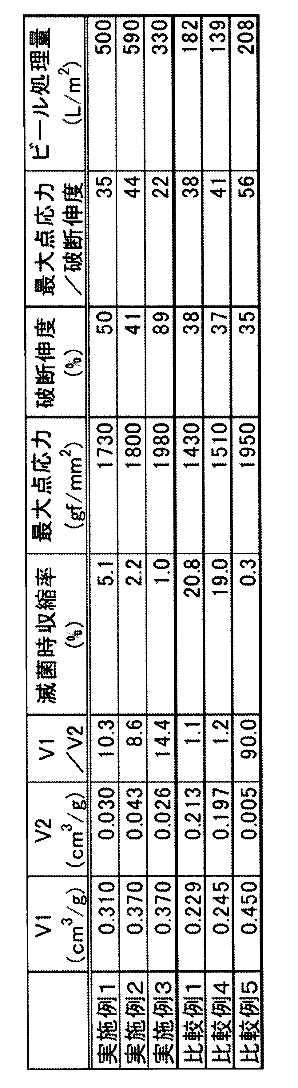
- Example 1 After the preparation in Reference Example 1, the mixture was immersed in methyl sulfoxide at 10 ° C. for 15 minutes, and the poor solvent was replaced with water. Table 1 shows the performance of the obtained hollow fiber membrane.
- Example 2 After the preparation in Reference Example 2, the mixture was immersed in a 50% by weight aqueous solution of ⁇ -butyrolactone at 50 ° C. for 60 minutes, and the poor solvent was replaced with water. Table 1 shows the performance of the obtained hollow fiber membrane.
- Example 3 After the preparation in Reference Example 2, the mixture was immersed in ⁇ -butyrolactone at 25 ° C. for 60 minutes, and the poor solvent was replaced with water. Table 1 shows the performance of the obtained hollow fiber membrane.
- Table 1 shows the performance of the hollow fiber membrane obtained in the same manner as in Example 2 except that the poor solvent immersion treatment was not performed.
- the separation membrane of the example has improved filtration performance by having a pore volume V1 having a pore diameter of 100 nm or more, a pore volume V2 having a pore diameter less than 100 nm, and their ratios in a specific range. , The amount of beer processed has improved. It was also found to be excellent in durability.
- the separation membrane produced by the method of the present invention is very useful as a separation membrane used in fermentation broth filtration because it has very high chemical durability and physical durability and has excellent filterability for fermentation broth.
Landscapes
- Chemical & Material Sciences (AREA)
- Chemical Kinetics & Catalysis (AREA)
- Engineering & Computer Science (AREA)
- Organic Chemistry (AREA)
- Health & Medical Sciences (AREA)
- General Health & Medical Sciences (AREA)
- Food Science & Technology (AREA)
- Biochemistry (AREA)
- Bioinformatics & Cheminformatics (AREA)
- General Engineering & Computer Science (AREA)
- Toxicology (AREA)
- Genetics & Genomics (AREA)
- Life Sciences & Earth Sciences (AREA)
- Wood Science & Technology (AREA)
- Zoology (AREA)
- Inorganic Chemistry (AREA)
- Manufacturing & Machinery (AREA)
- Separation Using Semi-Permeable Membranes (AREA)
- Distillation Of Fermentation Liquor, Processing Of Alcohols, Vinegar And Beer (AREA)
Abstract
Description
(1)有機高分子樹脂を含む分離膜であって、孔径100nm以上の細孔容積V1が0.3cm3/g以上0.5cm3/g以下であり、孔径100nm未満の細孔容積V2が0.02cm3/g以上0.1cm3/g未満であり、細孔容積V2と前記細孔容積V1との比V1/V2が3以上60以下である分離膜。
V1:水銀圧入法で測定される孔径100nm以上の細孔容積
V2:ガス吸着法で測定される孔径100nm未満の細孔容積
(2)前記V1/V2が3以上20以下である、前記(1)に記載の分離膜。
(3)前記分離膜はフッ化ビニリデン樹脂を含有する球状体の連続した構造を有する中空糸膜である、前記(1)または(2)に記載の分離膜。
(4)前記中空糸膜の破断伸度が38%以上である、前記(3)に記載の分離膜。
(5)前記中空糸膜を125℃の水蒸気雰囲気で20時間加熱処理した時の中空糸膜長の収縮率が0.5%以上である、前記(3)または(4)に記載の分離膜。
(6)前記分離膜が親水性高分子を含有し、前記親水性高分子は、2種類以上のモノマー単位から構成される共重合体を含有し、下記式(1)に基づいて算出される前記親水性高分子の水和エネルギー密度が、40~70cal・mol-1・Å-3である、前記(1)から(5)のいずれか1に記載の分離膜。

1.分離膜
(1)有機高分子樹脂
本発明の実施形態において、分離膜は有機高分子樹脂を含む。
本発明の実施形態において、分離膜は多孔質である。すなわち分離膜はその内部に細孔を有する。細孔は特定の形状に限定されない。
分離膜は、有機高分子樹脂で形成された0.5~15μmの太さの固形部と、固形部間の空隙を有しており、固形部内にも微細な空隙が存在する。
本発明の実施形態の分離膜において、細孔の平均孔径は10~10000nmであることが好ましい。細孔の平均孔径は、より好ましくは50~5000nmの範囲であり、更に好ましくは100~3000nmの範囲である。いずれの好ましい下限値もいずれの好ましい上限値と組み合わせることができる。


分離膜内の孔径100nm未満の細孔は、主に固形部内の空隙であり、固形部間の微細な空隙も含む。孔径100nm以上の細孔は固形部間の大きな空隙である。
ガス吸着法では、例えば、分離膜に吸着している水等を除去した後、液体窒素温度での窒素ガス吸着測定を行い、相対圧(吸着平衡圧力/液体窒素温度での飽和蒸気圧)0.99の際の窒素ガス吸着量(液体換算)より、分離膜の細孔容積V(cm3/g)を測定すればよい。
本発明の実施形態の分離膜において、固形部が球状構造を有することが好ましい。球状構造とは、球状体が連続した構造である。分離膜の内部がこのような構造を有することにより、固形部(球状体)間の空隙が収縮しにくく、高い純水透過性能を維持できる。また、球状構造により、従来の網目状の構造に比べて高い強度および高い透水性能を実現することができる。
また、球状構造はフッ化ビニリデン樹脂を含有することが好ましく、分離膜は球状構造を有すると共に中空糸膜であることが好ましい。中空糸膜の一部分を図1に例示する。分離膜の内部とは、分離膜が図1に示す中空糸膜1である場合は、外表面11を除いた部分、つまり中空糸膜1の実質的な内部および/または内表面12をいう。
球状体20は、略球体乃至略楕円体である。図2に示すように、球状体20は他の球状体20と連結しているため、その球面または楕円体面の全体を観察することはできない。しかし、外形に表れている形状から、その直径、長径および短径を推定することができる。
球状体間の連結は、球状体同士が直接接着することで形成されていてもよいし、球状体の間の非球状な部分(くびれと言い換えられる)21によって形成されていてもよい。
球状体間の空隙22は、上述した固形部間の空隙である。固形部について上述したように、球状体内にも微細な空隙が存在する。
前記球状体の直径は、中空糸膜の断面および/または内表面を球状構造が明瞭に確認できる倍率で走査型電子顕微鏡等を用いて写真を撮り、10個以上、好ましくは20個以上の任意の球状体の直径を測定し、平均して求める。写真を画像処理装置で解析し、等価円直径の平均を求めることも好ましく採用できる。球状体の密度は103~108個/mm2の範囲が好ましく、より好ましくは104~106個/mm2の範囲である。球状体の密度が103個/mm2以上であることで発酵液処理に求められる高い強度が実現でき、108個/mm2以下であることで高い純水透過性能が得られる。
本発明の実施形態の分離膜は親水性高分子を含有することが好ましい。また、前記親水性高分子は、2種類以上のモノマー単位から構成される共重合体を含有し、下記式(1)に基づいて算出される前記親水性高分子の水和エネルギー密度が、40~70cal・mol-1・Å-3であることが好ましい。

本発明の実施形態の分離膜が中空糸膜の形状をとる場合、中空糸の外径と膜厚は、膜の強度を損なわない範囲で、中空糸膜内部長手方向の圧力損失を考慮し、膜モジュールとして透水量が目標値になるように決めればよい。すなわち、外径が、太ければ圧力損失の点で有利になるが、充填本数が減り、膜面積の点で不利になる。
次に、本発明の実施形態の分離膜の中でも特にフッ化ビニリデン樹脂から中空糸膜を得るための方法について述べるが、本発明はこれらの製造方法例によってなんら限定されるものではない。
以下の実施例では本発明の分離膜が中空糸膜の形状をとる場合について説明する。
セイコー電子(株)製の示差走査熱量計(DSC-6200)を用いて、乾燥状態の中空糸膜を密封式DSC容器に密封し、昇温速度10℃/minで昇温する過程で観察されるピークのピークトップ温度を中空糸膜の融点Tmとした。
中空糸膜を次の方法により絶乾した。熱処理をしていない、水で湿潤した状態の中空糸膜は、-20℃で約50時間凍結乾燥した後、さらに常温で約8時間真空乾燥した。熱処理した中空糸膜は、常温で約8時間真空乾燥した。この絶乾中空糸膜を約5mmの長さに切断し、試料重量を電子天秤((株)島津製作所製、AW220)で秤量した。細孔径分布はマイクロメリテックス社製ポアサイザー9320により測定した。試験片を装置付属の約5cm3のガラス製のセルに封入し減圧下に水銀を注入した後、装置付属の耐圧容器中でオイルを介して約4kPa~207MPa(細孔径約7nm~350μmに対応)の範囲で昇圧することで行った。水銀の表面張力は484dyn/cm、水銀の接触角は141.3°を用いて計算した。孔径100nm以上の細孔容積をV1とした。
減圧乾燥した中空糸膜について約10cmの長さに切断し、試料重量を電子天秤((株)島津製作所製、AW220)で秤量した。自動比表面積・細孔径分布測定装置(マイクロトラック・ベル社製、BELSORP-mini II)を用い、窒素ガス吸着量を測定した。付属の解析プログラムを用いてBET比表面積を算出した。孔径100nm未満の細孔容積をV2とした。
複数本の中空糸膜を約30cmの長さに切断し、ポリエチレンフィルムで巻いて中空糸膜束とした。この中空糸膜束を円筒型のポリカーボネート製モジュールケースに挿入し、両末端をエポキシポッティング剤で固めた。端部を切断して、両末端が開口したモジュールを得た。中空糸膜の本数は、中空糸膜内径基準の膜面積が100~200cm2となるよう適宜設定した。なお、円筒状のモジュールケースには両端部付近の2箇所にポートを設け、中空糸膜の外面を流体が灌流できるようにし、両末端には液の出入り口を有するエンドキャップを装着して、中空糸膜の中空部を流体が灌流できるようにした。
中空糸膜を次の方法により滅菌処理した。中空糸膜を40cmの長さに切断し、オートクレーブ装置(トミー精工社製、LSX-300)を用い、設定温度を125℃とし、20時間の滅菌処理を行った。中空糸膜の長さを測定し、収縮長さを滅菌前の中空糸膜長さで除することで収縮率を算出した。
引張試験機((株)東洋ボールドウィン製TENSILON/RTM100)を用いて、フルスケール5kgの荷重でクロスヘッドスピード50mm/分にて測定し求めた。試験片は、試験長50mmを湿潤状態で測定に用いた。
ビール酵母を含有した市販の無ろ過ビール「銀河高原ビール」を(以下、評価用ビールと呼称する)使用した。モジュール内にRO水を充填し1時間以上放置した後、中空糸膜の外側のRO水を排出した後、中空部に存在する水を評価用ビールで置換した。容器内に0℃を維持した評価用ビール2Lを用意し、この容器からポンプを介して評価用ビールが中空糸膜の外面を灌流して容器に戻ると同時に、中空糸膜によってろ過されたろ液は評価用ビールが入っている容器とは異なる容器で採取するよう回路を組んだ。その際、モジュールへの評価用ビールの入口圧と出口圧およびろ過側の圧を測定できるようにした。モジュール入口を、評価用ビールが1.5m/secの流速で流れるように、評価用ビールを導入した。また、ろ過速度は、100[L/m2/h]になるように調整した。この状態で、中空糸膜外面に評価用ビールを5±3℃で灌流、一部をろ過するクロスフローろ過を継続して実施した。所定の時間毎に入口圧、出口圧およびろ過側の圧力を測定し、膜間圧力差(TMP)が100kPaまで上昇する時間[h]を測定して、ビール処理量を算出した。
TMP=(Pi+Po)/2-Pf とした。
ここで、Piは入口圧、Poは出口圧およびPfはろ過側の圧である。
重量平均分子量41.7万のフッ化ビニリデンホモポリマー28重量%とジメチルスルホキシド72重量%を120℃で溶解した。このフッ化ビニリデンホモポリマー溶液を二重管式口金の外側の管から吐出し、同時にジメチルスルホキシド90重量%の水溶液を二重管式口金の内側の管から吐出し、ジメチルスルホキシド85重量%の水溶液からなる温度10℃の浴中で固化させた後、水洗して90℃の水中で1.4倍に延伸した。得られた中空糸膜の融点は170℃であり、球状構造であった。
重量平均分子量41.7万のフッ化ビニリデンホモポリマー38重量%とγ-ブチロラクトン62重量%を150℃で溶解した。このフッ化ビニリデンホモポリマー溶液を二重管式口金の外側の管から吐出し、同時にγ-ブチロラクトン85重量%の水溶液を二重管式口金の内側の管から吐出し、γ-ブチロラクトン85重量%の水溶液からなる温度9℃の浴中で固化させた後、水洗して85℃の水中で1.5倍に延伸した。得られた中空糸膜の融点は173℃であり、球状構造であった。
参考例1で作製した後、10℃のメチルスルホキシドに15分間浸漬し、水により貧溶媒を置換した。得られた中空糸膜の性能を表1に示す。
参考例2で作製した後、50℃のγ-ブチロラクトン50重量%の水溶液に60分間浸漬し、水により貧溶媒を置換した。得られた中空糸膜の性能を表1に示す。
参考例2で作製した後、25℃のγ-ブチロラクトンに60分間浸漬し、水により貧溶媒を置換した。得られた中空糸膜の性能を表1に示す。
貧溶媒浸漬処理をしなかった以外は実施例2と同様にして得られた中空糸膜の性能を表1に示す。
参考例2で作製した後、70℃のγ-ブチロラクトンに60分間浸漬し、水により貧溶媒を置換した。中空糸膜細孔は完全に溶解閉塞された。
参考例2で作製した後、90℃のγ-ブチロラクトン70重量%の水溶液に60分間浸漬し、水により貧溶媒を置換した。中空糸膜細孔は完全に溶解閉塞された。
参考例2で作製した後、90℃の熱水中に60分間浸漬させた。得られた中空糸膜の性能を表1に示す。
風乾後の中空糸膜を、140℃で60分間熱処理した。得られた中空糸膜の性能を表1に示す。
Claims (6)
- 有機高分子樹脂を含む分離膜であって、
孔径100nm以上の細孔容積V1が0.3cm3/g以上0.5cm3/g以下であり、
孔径100nm未満の細孔容積V2が0.02cm3/g以上0.1cm3/g未満であり、
細孔容積V2と前記細孔容積V1との比V1/V2が3以上60以下である分離膜。
V1:水銀圧入法で測定される孔径100nm以上の細孔容積
V2:ガス吸着法で測定される孔径100nm未満の細孔容積 - 前記V1/V2が3以上20以下である、請求項1に記載の分離膜。
- 前記分離膜はフッ化ビニリデン樹脂を含有する球状体の連続した構造を有する中空糸膜である、請求項1または2に記載の分離膜。
- 前記中空糸膜の破断伸度が38%以上である、請求項3に記載の分離膜。
- 前記中空糸膜を125℃の水蒸気雰囲気で20時間加熱処理した時の中空糸膜長の収縮率が0.5%以上である、請求項3または4に記載の分離膜。
- 前記分離膜が親水性高分子を含有し、
前記親水性高分子は、2種類以上のモノマー単位から構成される共重合体を含有し、下記式(1)に基づいて算出される前記親水性高分子の水和エネルギー密度が、40~70cal・mol-1・Å-3である、請求項1から5のいずれか1項に記載の分離膜。

Priority Applications (6)
| Application Number | Priority Date | Filing Date | Title |
|---|---|---|---|
| US17/631,250 US11617991B2 (en) | 2019-07-31 | 2020-07-31 | Separation film |
| CN202080055595.4A CN114206482B (zh) | 2019-07-31 | 2020-07-31 | 分离膜 |
| KR1020227003422A KR102464645B1 (ko) | 2019-07-31 | 2020-07-31 | 분리막 |
| EP20847111.0A EP4005658A4 (en) | 2019-07-31 | 2020-07-31 | Separation film |
| AU2020323457A AU2020323457B2 (en) | 2019-07-31 | 2020-07-31 | Separation film |
| JP2020542913A JP6958745B2 (ja) | 2019-07-31 | 2020-07-31 | 分離膜 |
Applications Claiming Priority (2)
| Application Number | Priority Date | Filing Date | Title |
|---|---|---|---|
| JP2019-141089 | 2019-07-31 | ||
| JP2019141089 | 2019-07-31 |
Publications (1)
| Publication Number | Publication Date |
|---|---|
| WO2021020571A1 true WO2021020571A1 (ja) | 2021-02-04 |
Family
ID=74228906
Family Applications (1)
| Application Number | Title | Priority Date | Filing Date |
|---|---|---|---|
| PCT/JP2020/029513 Ceased WO2021020571A1 (ja) | 2019-07-31 | 2020-07-31 | 分離膜 |
Country Status (7)
| Country | Link |
|---|---|
| US (1) | US11617991B2 (ja) |
| EP (1) | EP4005658A4 (ja) |
| JP (1) | JP6958745B2 (ja) |
| KR (1) | KR102464645B1 (ja) |
| CN (1) | CN114206482B (ja) |
| AU (1) | AU2020323457B2 (ja) |
| WO (1) | WO2021020571A1 (ja) |
Cited By (1)
| Publication number | Priority date | Publication date | Assignee | Title |
|---|---|---|---|---|
| WO2024070989A1 (ja) * | 2022-09-30 | 2024-04-04 | 東レ株式会社 | 分離膜、その製造方法、ろ過方法及び膜ろ過装置 |
Citations (10)
| Publication number | Priority date | Publication date | Assignee | Title |
|---|---|---|---|---|
| WO2002058828A1 (en) | 2001-01-23 | 2002-08-01 | Innovasep Technology Corporation | Asymmetric hollow fiber membranes |
| WO2003031038A1 (en) * | 2001-10-04 | 2003-04-17 | Toray Industries, Inc. | Hollow fiber film and method for production thereof |
| WO2006043363A1 (ja) * | 2004-10-21 | 2006-04-27 | Matsushita Electric Industrial Co., Ltd. | 酸素透過膜、酸素透過シート、およびこれらを含む電池 |
| JP2008105016A (ja) | 2006-09-26 | 2008-05-08 | Toray Ind Inc | ポリフッ化ビニリデン系樹脂からなる中空糸膜およびその製造方法 |
| WO2010035793A1 (ja) | 2008-09-26 | 2010-04-01 | 旭化成ケミカルズ株式会社 | 清澄化されたバイオ医薬培養液を製造するための多孔質中空糸膜の使用 |
| US20110155659A1 (en) * | 2008-08-20 | 2011-06-30 | Kolon Industries, Inc. | Porous membrane and preparation method thereof |
| WO2016006611A1 (ja) * | 2014-07-07 | 2016-01-14 | 東レ株式会社 | 分離膜およびその製造方法 |
| WO2016182015A1 (ja) | 2015-05-13 | 2016-11-17 | 東洋紡株式会社 | 多孔質中空糸膜及びその製造方法 |
| WO2017155034A1 (ja) | 2016-03-11 | 2017-09-14 | 旭化成株式会社 | 多孔質膜、多孔質膜モジュール、多孔質膜の製造方法、清澄化された液体の製造方法およびビールの製造方法 |
| JP2019141089A (ja) | 2016-03-18 | 2019-08-29 | 株式会社村田製作所 | 金属製多孔膜、それを用いた分級方法、および分級装置 |
Family Cites Families (16)
| Publication number | Priority date | Publication date | Assignee | Title |
|---|---|---|---|---|
| JP3070998B2 (ja) | 1991-09-03 | 2000-07-31 | ダイセル化学工業株式会社 | 中空糸型膜分離モジュールの製造方法および中空糸型膜分離モジュール |
| JP4271750B2 (ja) * | 1998-03-16 | 2009-06-03 | 旭化成ケミカルズ株式会社 | 微多孔膜及びその製造方法 |
| US20040135274A1 (en) | 1998-03-16 | 2004-07-15 | Shigenobu Matsuda | Microporous membrane |
| JP3724412B2 (ja) * | 2001-11-02 | 2005-12-07 | 東レ株式会社 | 中空糸膜の製造方法および中空糸膜モジュール |
| WO2004043579A1 (ja) * | 2002-11-12 | 2004-05-27 | Mitsubishi Rayon Co., Ltd. | 複合多孔質膜及びその製造方法 |
| JP5076320B2 (ja) * | 2006-01-11 | 2012-11-21 | 東洋紡績株式会社 | ポリフッ化ビニリデン系中空糸型微多孔膜の製造方法 |
| CN102159305B (zh) | 2008-09-19 | 2015-08-19 | 东丽株式会社 | 分离膜及其制造方法 |
| AU2010204844B2 (en) | 2009-01-14 | 2013-01-10 | Accenture Global Services Limited | Distribution system analysis using meter data |
| WO2011058983A1 (ja) * | 2009-11-10 | 2011-05-19 | 東レ株式会社 | 化学品製造用中空糸膜モジュールおよび化学品の製造方法 |
| MX2013001969A (es) | 2010-08-18 | 2013-06-05 | Imerys Filtration Minerals Inc | Ayudas de filtro compuestas que tienen caracteristicas novedosas en el tamaño de los poros. |
| EP2905068A4 (en) | 2012-10-02 | 2016-08-10 | Jnc Corp | MICROPOROUS MEMBRANE AND MANUFACTURING METHOD THEREFOR |
| JP2015160185A (ja) * | 2014-02-28 | 2015-09-07 | Jnc株式会社 | メンブレンバイオリアクター |
| US10456753B2 (en) * | 2015-08-31 | 2019-10-29 | Toray Industries, Inc. | Porous hollow fiber membrane |
| RU2735601C2 (ru) | 2016-08-05 | 2020-11-05 | Торэй Индастриз, Инк. | Сополимер и разделительная мембрана, устройство медицинского назначения и устройство для очистки крови, в котором используют этот сополимер |
| JP6365798B1 (ja) | 2016-09-21 | 2018-08-01 | 住友ベークライト株式会社 | 複合成形体および複合成形体の製造方法 |
| JP7169129B2 (ja) * | 2017-09-07 | 2022-11-10 | 旭化成株式会社 | 多孔質膜を用いた糖化液の製造方法 |
-
2020
- 2020-07-31 JP JP2020542913A patent/JP6958745B2/ja active Active
- 2020-07-31 WO PCT/JP2020/029513 patent/WO2021020571A1/ja not_active Ceased
- 2020-07-31 CN CN202080055595.4A patent/CN114206482B/zh active Active
- 2020-07-31 AU AU2020323457A patent/AU2020323457B2/en active Active
- 2020-07-31 KR KR1020227003422A patent/KR102464645B1/ko active Active
- 2020-07-31 US US17/631,250 patent/US11617991B2/en active Active
- 2020-07-31 EP EP20847111.0A patent/EP4005658A4/en not_active Withdrawn
Patent Citations (10)
| Publication number | Priority date | Publication date | Assignee | Title |
|---|---|---|---|---|
| WO2002058828A1 (en) | 2001-01-23 | 2002-08-01 | Innovasep Technology Corporation | Asymmetric hollow fiber membranes |
| WO2003031038A1 (en) * | 2001-10-04 | 2003-04-17 | Toray Industries, Inc. | Hollow fiber film and method for production thereof |
| WO2006043363A1 (ja) * | 2004-10-21 | 2006-04-27 | Matsushita Electric Industrial Co., Ltd. | 酸素透過膜、酸素透過シート、およびこれらを含む電池 |
| JP2008105016A (ja) | 2006-09-26 | 2008-05-08 | Toray Ind Inc | ポリフッ化ビニリデン系樹脂からなる中空糸膜およびその製造方法 |
| US20110155659A1 (en) * | 2008-08-20 | 2011-06-30 | Kolon Industries, Inc. | Porous membrane and preparation method thereof |
| WO2010035793A1 (ja) | 2008-09-26 | 2010-04-01 | 旭化成ケミカルズ株式会社 | 清澄化されたバイオ医薬培養液を製造するための多孔質中空糸膜の使用 |
| WO2016006611A1 (ja) * | 2014-07-07 | 2016-01-14 | 東レ株式会社 | 分離膜およびその製造方法 |
| WO2016182015A1 (ja) | 2015-05-13 | 2016-11-17 | 東洋紡株式会社 | 多孔質中空糸膜及びその製造方法 |
| WO2017155034A1 (ja) | 2016-03-11 | 2017-09-14 | 旭化成株式会社 | 多孔質膜、多孔質膜モジュール、多孔質膜の製造方法、清澄化された液体の製造方法およびビールの製造方法 |
| JP2019141089A (ja) | 2016-03-18 | 2019-08-29 | 株式会社村田製作所 | 金属製多孔膜、それを用いた分級方法、および分級装置 |
Non-Patent Citations (1)
| Title |
|---|
| See also references of EP4005658A4 |
Cited By (3)
| Publication number | Priority date | Publication date | Assignee | Title |
|---|---|---|---|---|
| WO2024070989A1 (ja) * | 2022-09-30 | 2024-04-04 | 東レ株式会社 | 分離膜、その製造方法、ろ過方法及び膜ろ過装置 |
| JPWO2024070989A1 (ja) * | 2022-09-30 | 2024-04-04 | ||
| JP7647921B2 (ja) | 2022-09-30 | 2025-03-18 | 東レ株式会社 | 分離膜、その製造方法、ろ過方法及び膜ろ過装置 |
Also Published As
| Publication number | Publication date |
|---|---|
| AU2020323457B2 (en) | 2026-02-05 |
| AU2020323457A1 (en) | 2022-02-24 |
| EP4005658A1 (en) | 2022-06-01 |
| US20220266204A1 (en) | 2022-08-25 |
| KR20220019074A (ko) | 2022-02-15 |
| CN114206482B (zh) | 2023-01-03 |
| KR102464645B1 (ko) | 2022-11-09 |
| JPWO2021020571A1 (ja) | 2021-09-13 |
| US11617991B2 (en) | 2023-04-04 |
| CN114206482A (zh) | 2022-03-18 |
| EP4005658A4 (en) | 2023-08-23 |
| JP6958745B2 (ja) | 2021-11-02 |
Similar Documents
| Publication | Publication Date | Title |
|---|---|---|
| CA2433786C (en) | Hollow fiber membrane and method of producing the same | |
| US9174174B2 (en) | Separation membrane and method for producing the same | |
| CN105473214B (zh) | 微孔聚偏二氟乙烯膜 | |
| CN102481528B (zh) | 氟类中空纤维膜及其制备方法 | |
| JP2010094670A (ja) | ポリフッ化ビニリデン系複合膜およびその製造方法 | |
| CN111107926A (zh) | 多孔中空丝膜和其制造方法 | |
| TW201622805A (zh) | 微孔性聚偏二氟乙烯平面膜 | |
| JP2019130522A (ja) | 中空糸膜、中空糸膜の製造方法、および中空糸膜を用いたビール、ワインまたは日本酒の製造方法 | |
| JP4835221B2 (ja) | 中空糸膜およびその製造方法 | |
| JP6958745B2 (ja) | 分離膜 | |
| WO2009119373A1 (ja) | 中空糸膜およびその製造方法 | |
| JP2003320228A (ja) | 微多孔膜の製造方法および微多孔膜 | |
| JP4931796B2 (ja) | フッ化ビニリデン系樹脂中空糸多孔膜、それを用いる水の濾過方法およびその製造方法 | |
| WO2007032331A1 (ja) | フッ化ビニリデン系樹脂中空糸多孔膜およびその製造方法 | |
| US20240216871A1 (en) | Hollow fiber membrane and manufacturing method therefor | |
| KR102267825B1 (ko) | 다공질 중공사막 및 그의 제조 방법 | |
| US11161069B2 (en) | Porous membrane | |
| KR102524285B1 (ko) | 다공질 중공사막 | |
| JP2022170736A (ja) | 分離膜 | |
| JP2021053636A (ja) | 発酵液のろ過方法 | |
| CN117222472A (zh) | 中空纤维膜及其制造方法 |
Legal Events
| Date | Code | Title | Description |
|---|---|---|---|
| ENP | Entry into the national phase |
Ref document number: 2020542913 Country of ref document: JP Kind code of ref document: A |
|
| 121 | Ep: the epo has been informed by wipo that ep was designated in this application |
Ref document number: 20847111 Country of ref document: EP Kind code of ref document: A1 |
|
| ENP | Entry into the national phase |
Ref document number: 20227003422 Country of ref document: KR Kind code of ref document: A |
|
| NENP | Non-entry into the national phase |
Ref country code: DE |
|
| ENP | Entry into the national phase |
Ref document number: 2020323457 Country of ref document: AU Date of ref document: 20200731 Kind code of ref document: A |
|
| ENP | Entry into the national phase |
Ref document number: 2020847111 Country of ref document: EP Effective date: 20220228 |