WO2021020573A1 - Dispositif de retrait d'agrafes - Google Patents
Dispositif de retrait d'agrafes Download PDFInfo
- Publication number
- WO2021020573A1 WO2021020573A1 PCT/JP2020/029515 JP2020029515W WO2021020573A1 WO 2021020573 A1 WO2021020573 A1 WO 2021020573A1 JP 2020029515 W JP2020029515 W JP 2020029515W WO 2021020573 A1 WO2021020573 A1 WO 2021020573A1
- Authority
- WO
- WIPO (PCT)
- Prior art keywords
- staple
- removal
- wedge plate
- paper
- crown
- Prior art date
- Legal status (The legal status is an assumption and is not a legal conclusion. Google has not performed a legal analysis and makes no representation as to the accuracy of the status listed.)
- Ceased
Links
Images


Classifications
-
- B—PERFORMING OPERATIONS; TRANSPORTING
- B25—HAND TOOLS; PORTABLE POWER-DRIVEN TOOLS; MANIPULATORS
- B25C—HAND-HELD NAILING OR STAPLING TOOLS; MANUALLY OPERATED PORTABLE STAPLING TOOLS
- B25C11/00—Nail, spike, and staple extractors
Definitions
- This disclosure relates to a staple removal device.
- Patent Documents 1 and 2 Conventionally, a technique relating to a staple removing device for removing staples from a bundle of paper has been disclosed (Patent Documents 1 and 2). This type of staple removing device removes staples from a bundle of paper by inserting a wedge-shaped plate between the bundle of paper and the crown portion of the staple.
- Patent Document 1 discloses a staple removing device in which a staple removing means is arranged at a position vertically lower than a sheet bundle and is driven by a driving means to remove staples from a vertically lower position. Further, in Patent Document 2, both legs of the staple needle are raised in a predetermined state in the step of raising the leg, and the central main body of the staple needle exposed on the binding paper is defined as the central main body of the staple needle and the surface of the binding paper. Disclosed is a staple removing device for staple needles, which comprises a needle pulling step of inserting a needle pulling standing piece that moves in parallel with an upright fork protruding piece that is inserted between the binding paper and the staple needle so as to be far apart from the staple paper. There is.
- the conventional staple removal device has the following problems. That is, in Patent Document 1, since the staple removing means rotates to remove the staple from the lower position, there is theoretically only one point where the height of the claw is maximum from the mounting table, and the staple to be removed is set as the above point. If it is not set correctly, there is a problem that the claws are not inserted between the crown portion of the staple and the paper surface, resulting in poor removal of the staple.
- Patent Document 2 since the needle pulling upright piece is translated, the removal point of the staple is not a point but a surface, but when the needle pulling upright piece moves in parallel with the mounting table, the tip portion thereof is the crown of the staple. There is a problem that the staple pulling stand cannot be smoothly inserted between the crown portion and the paper surface because it may be caught in the portion.
- the present invention makes it easy to insert the tip of the removing portion between the paper bundle and the crown portion of the staple when removing the staple from the paper bundle, and prevents the removal failure. It is an object of the present invention to provide a staple removal device.
- the first aspect of the present disclosure is a mounting table on which a stack of paper bound by staples is placed, a paper holding portion that holds the bundle of paper placed on the above-mentioned stand, and a position below the above-mentioned stand.
- a removing portion and a motor for moving the removing portion are provided, and the above-mentioned pedestal is provided with an opening from which the tip portion can protrude, and the tip portion is provided at least in front of the second position to the second position.
- the present invention relates to a staple removing device that moves while maintaining a state of protruding from the above-described stand through an opening until the staple is passed through.
- the tip of the removal portion is moved from the front of the second position until it passes through the second position in a state of protruding from the mounting table, the tip of the removal portion is moved between the paper bundle and the staple. It can be easily inserted, and it is possible to prevent the occurrence of removal defects during the removal operation.
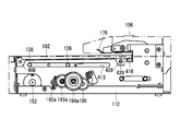
- FIG. 5 is a plan view of the inside of the staple removing device when the removing portion according to the first embodiment is in the standby position. It is a top view of the drive part inside the staple removal device which concerns on 1st Embodiment.
- FIG. 11A It is a side view which shows the operation of the staple pulling mechanism which moves to the removal position which concerns on 1st Embodiment. It is a side view of the main part which shows the operation of the staple pulling mechanism shown in FIG. 12A. It is a perspective view which shows the operation of the paper holding mechanism in the standby position which concerns on 1st Embodiment. It is a perspective view which shows the operation of the paper holding mechanism which moves to a pressing position which concerns on 1st Embodiment.
- FIG. 19A is an enlarged view of a main part of the wedge plate and the mounting table shown in FIG. 19A. It is explanatory drawing of the operation of the wedge plate of the staple removal device which moves to the removal position which concerns on 2nd Embodiment. It is an enlarged view of the main part of the wedge plate and the mounting stand shown in FIG. 20A.
- FIG. 22A is an enlarged view of a main part of the wedge plate and the mounting table shown in FIG. 22A. It is explanatory drawing of the operation of the wedge plate of the staple removal device which moves to the removal position which concerns on 3rd Embodiment. It is an enlarged view of the main part of the wedge plate and the mounting stand shown in FIG. 23A. It is a side view of the staple removal device which concerns on 4th Embodiment.
- FIG. 26A is an enlarged view of a main part of the wedge plate and the mounting table shown in FIG. 26A. It is an exploded perspective view of the staple removal device which concerns on modification 1-1. It is a perspective view of the staple removal device which concerns on modification 1-1. It is a side view of the wedge plate which concerns on modification 1-1.
- FIG. 5 is a cross-sectional view taken along the line AA of the removal portion shown in FIG. 45A. It is a side view which shows the operation of the staple removal device. It is a side view which shows the operation of the staple removal device. It is a side view which shows the operation of the staple removal device. It is a side view which shows the operation of the staple removal device. It is a side view which shows the operation of the staple removal device. It is a side view which shows the operation of the staple removal device. It is a side view which shows the operation of the staple removal device. It is a side view which shows the operation of the staple removal device. It is a side view which shows the operation of the staple removal device.
- FIG. 4 is a cross-sectional view taken along the line BB of the wedge plate shown in FIG. 49A.
- FIG. 5 is a cross-sectional view taken along the line CC of the removal portion shown in FIG. 51A. It is a top view of the removal part which concerns on modification 3-4. It is a side view of the removal part which concerns on modification 3-4. It is a bottom view of the removal part which concerns on modification 3-4. It is a DD line sectional view of the removal part shown in FIG. 52A which concerns on modification 3-4. It is a top view of the removal part which concerns on modification 3-5. It is a side view of the removal part which concerns on modification 3-5. It is a bottom view of the removal part which concerns on modification 3-5.
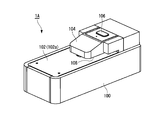
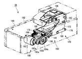
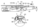
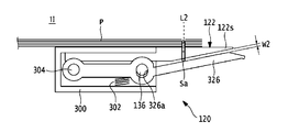
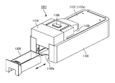
- FIG. 1A is a front perspective view of the staple removing device 1A
- FIG. 1B is a rear perspective view of the staple removing device 1A
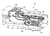
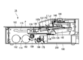
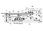
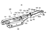
- 2A is a right front left rear perspective view of the inside of the staple removing device 1A
- FIG. 2B is a left front right rear perspective view of the inside of the staple removing device 1A.
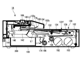
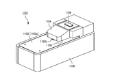
- the staple removing device 1A is a device for automatically removing (removing) staples from a bundle of paper bound by staples, and includes a housing 100 having a substantially rectangular parallelepiped shape and a mounting table 102 on which the bundle of paper is placed. , Located below the mounting table 102 (inside the housing 100 with respect to the mounting table 102), it drives the removing unit 120 and the removing unit 120 for removing staples from the paper bundle mounted on the mounting table 102.
- the first motor 152 and the accommodating portion 200 accommodating the staples removed by the removing unit 120 are provided.
- a cover portion 104 that covers a part of the mounting table 102 is provided above the mounting table 102 (the side on which the paper bundle is placed with respect to the mounting table 102).
- a predetermined gap is formed between the cover portion 104 and the mounting table 102, and a bundle of paper is inserted into this gap.
- An activation switch 106 for operating the staple removal device 1A is provided on the upper surface of the cover portion 104.
- the side where the accommodating portion 200 is provided is the rear side of the staple removal device 1A, and the opposite side is the front side of the staple removal device 1A.
- the housing 100 is a substantially rectangular parallelepiped box with an opening at the top, and a removing portion 120, a first motor 152, an accommodating portion 200, and the like are provided inside.
- the mounting table 102 is provided so as to cover the opening above the housing 100, and has a mounting surface 102a for mounting a bundle of paper.
- An opening 102b is formed on the mounting surface 102a so that a part of the removing portion 120 can be projected.
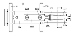
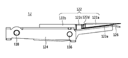
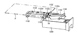
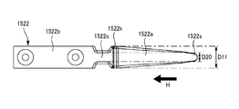
- the removing portion 120 has a predetermined length from the tip portion 122s to the base end portion 122k.
- the removing portion 120 includes a tip portion 122s that can be inserted between the paper bundle and the staple (crown portion Sa), and the wedge plate main body 122a, which is the first portion for removing the staple from the paper bundle, and racks 130 and 131. It has a wedge plate base portion 122f which is a second part driven by the driving force of the first motor 152 received in the above, and a constricted part 122c which is a third part located between the first part and the second part.
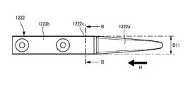
- the wedge plate body 122a is composed of an elongated plate-shaped member, and at least the tip portion 122s thereof is formed in a wedge shape so as to be easily inserted between the paper bundle and the staples and to easily pull out the staples from the paper bundle.
- the wedge plate main body 122a has a tapered shape from the base end portion 122k toward the tip end portion 122s. Specifically, in the side view, the plate thickness is gradually reduced from the base end portion 122k toward the tip end portion 122s, and in the top view, the plate width is gradually narrowed toward the tip end portion 122s. It is configured in.
- the wedge plate base 122f supports the wedge plate main body 122a via the constricted portion 122c, and also has a role of receiving the power from the first motor 152 by the racks 130 and 131 and transmitting it to the wedge plate main body 122a.
- the wedge plate base portion 122f includes a blade holder 124 formed of a flat plate having a substantially U-shaped cross section, and a pair of racks 130 and 131 attached to the side surfaces of the blade holder 124.
- a wedge plate main body 122a and an attachment portion 122b extending from the wedge plate base portion 122f are attached to the upper surface of the blade holder 124.
- the racks 130 and 131 are plate-shaped members having substantially the same length as the longitudinal direction of the blade holder 124, and a plurality of teeth (rack) that mesh with the pinion 158, which will be described later, are formed on the lower surface thereof, and the first motor 152. Receives the driving force of.
- a paper bundle insertion port 108 for setting a paper bundle in the cover portion 104 is provided between the mounting table 102 and the cover portion 104.
- the start switch 106 is provided on the upper surface of the cover portion 104 so that the user can easily operate it, and is composed of a button for operating the staple removing device 1A.
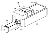
- the accommodating portion 200 is a box body having an opening at the upper side, and is configured to be removable with respect to the opening 100a formed on the rear end surface of the housing 100.
- the accommodating portion 200 is arranged in a space portion in the lower rear part of the housing 100 than the central portion.
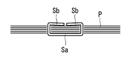
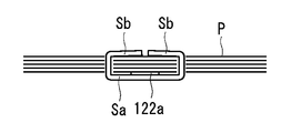
- the staple S in a state in which the paper bundle P is bound will be described with reference to FIG. 17A described later.
- the staple S has a crown portion Sa and a pair of leg portions Sb, Sb formed by bending both ends of the crown portion Sa in the longitudinal direction.
- the paper bundle P penetrates a pair of staples Sb, Sb from the bottom layer of a plurality of stacked sheets toward the top layer, and bends the penetrated legs Sb, Sb inward. It is bound by that.
- the binding position of the staple S is, for example, a corner or an edge of the paper. In the present embodiment, the staple S is removed from such a bundle of paper P.
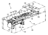
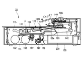
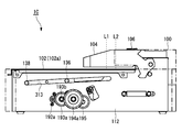
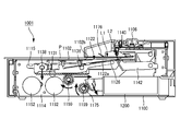
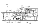
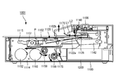
- FIG. 2A is a right front perspective view of the inside of the staple removing device 1A when the removing unit 120 is in the standby position
- FIG. 2B is a left front perspective view of the inside of the staple removing device 1A when the removing unit 120 is in the standby position
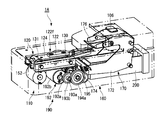
- FIG. 2C is a plan view of the inside of the staple removal device 1A when the removal unit 120 is in the standby position
- FIG. 2D is a plan view of the first drive unit 150 and the like inside the staple removal device 1A
- FIG. 2E shows the removal unit 120. It is a side view of the inside of the staple removal device 1A in the standby position.
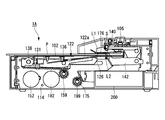
- FIG. 3 is a side sectional view of the inside of the staple removing device 1A when the removing portion 120 is in the standby position.
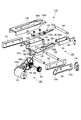
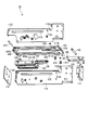
- FIG. 4 is an exploded perspective view of the staple removing mechanism 110.
- 5A is a plan view of the removal unit 120
- FIG. 5B is a side view of the removal unit 120
- FIG. 5C is a cross-sectional view of the removal unit 120 along the line AA.
- FIG. 6 is an exploded perspective view of the paper holding mechanism 160.
- the staple removing device 1A includes a staple removing mechanism 110 that removes the staple S from the paper bundle P, a paper holding mechanism 160 that presses the paper bundle P placed on the mounting table 102, and the above-mentioned accommodating portion 200. ing.
- the staple removing mechanism 110 is arranged inside the housing 100 below the mounting surface 102a of the mounting table 102, and is inserted between the paper bundle P and the staples to form a paper bundle. It has a removing unit 120 for removing staples S from P, a pressing unit 140 (regulating unit), and a first driving unit 150 for driving the removing unit 120.
- the removing portion 120 has a wedge plate 122 inserted between the crown portion Sa of the staple S and the paper bundle P, and the wedge plate 122 of the crown portion Sa and the paper bundle P.
- the racks 130 and 131 to be moved between them are provided.
- a blade holder 124 to which the wedge plate 122 is attached a crown holder 126 that supports the crown portion Sa of the staple S, and a holder 128 that regulates the position of the wedge plate 122.
- a blade holder 124 to which the wedge plate 122 is attached a crown holder 126 that supports the crown portion Sa of the staple S
- a holder 128 that regulates the position of the wedge plate 122.
- the wedge plate 122 is composed of an elongated plate-shaped member, and includes a wedge plate main body 122a, a mounting portion 122b, and a constricted portion 122c.
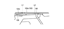
- the tip 122s is configured to be movable along the plane of the mounting table 102 between the standby position L1 and the removal position L2, and when the tip 122s moves to the removal position L2, the tip 122s is the paper bundle P and the staple. It is inserted between and.
- the standby position L1 of the removing unit 120 means a position where the tip portion 122s of the removing unit 120 is stopped before starting the removing operation.
- the removal position L2 of the removal unit 120 means that the removal unit 120 starts the removal operation, the removal unit 120 is inserted between the crown portion Sa of the staple S and the paper bundle P, and the staple S is removed from the paper bundle P. It means the position to start.
- the removal position L2 is a position at least horizontally separated from the standby position L1.
- the mounting portion 122b is integrally formed on the side of the base end portion 122k of the wedge plate main body 122a, and is mounted on the upper surface of the blade holder 124.
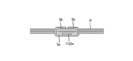
- the constricted portion 122c is a substantially central portion in the longitudinal direction of the wedge plate 122, and is formed between the wedge plate main body 122a and the mounting portion 122b. As shown in FIG. 5A, at least a part of the width dimension D1 of the constricted portion 122c is narrower than the width dimension D2 of the base end portion 122k of the wedge plate main body 122a, and when the staple S separates from the wedge plate 122, The width dimension D3 (see FIG.
- the "width dimension” means the dimension in the width direction of the wedge plate.
- the "width direction” is the left-right direction in this embodiment, and may be a direction perpendicular to the thickness direction (height direction) and the longitudinal direction (movement direction of the wedge plate) of the wedge plate.
- the blade holder 124 is composed of a flat plate having a substantially U-shaped cross section, a mounting portion 122b is mounted on the upper surface, and the blade holder 124 is arranged so as to be overlapped above the crown holder 126.
- the crown holder 126 is arranged below the wedge plate 122 with the blade holder 124 in between, and supports the crown portion Sa of the staple S removed from the paper bundle P.
- the crown holder 126 has a groove portion 126a for preventing contact with the pressing portion 140 when the wedge plate 122 moves from the front to the rear, and a staple S removed from the paper bundle P for dropping the staple S into the accommodating portion 200.
- the opening 126b of the crown holder 126 and the constricted portion 122c of the wedge plate 122 attached to the blade holder 124 are arranged so as to be in the same position in a plan view.
- the groove portion 126a is cut out from the tip end portion of the crown holder 126 to substantially the center portion, and has a width slightly wider than the width of the pressing portion 140.
- the opening 126b is formed at a substantially central portion in the longitudinal direction of the crown holder 126 and continuously on the proximal end side of the groove portion 126a, and has a width at least wider than the length of the crown portion Sa of the staple S.
- a spring 125 is arranged between the lower surface on the other end side of the blade holder 124 and the upper surface on the other end side of the crown holder 126, and the elastic force of the spring 125 causes one end side of the wedge plate 122 and one end side of the crown holder 126. Is urged in the direction of approaching.
- one end side indicates the rear side of the staple removal device 1A
- the other end side indicates the front side of the staple removal device 1A.
- the restricting portions 127a and 127b are integrally formed on the upper surface of the crown holder 126 on the base end side and at both ends in the width direction, and face the blade holder 124 side from the upper surface thereof. Is protruding.
- the regulating portions 127a and 127b come into contact with the lower surface 124c of the blade holder 124 when the tip end side of the crown holder 126 is opened to a preset opening amount (hereinafter referred to as a set value) with respect to the wedge plate 122, and the crown holder 126 It is regulated so that the tip side of is not opened more than the set value.
- the regulating portions 127a and 127b may be formed of a member different from the crown holder 126. Further, the shape of the regulating portions 127a and 127b is, for example, a rectangular shape having a curved upper end, but the shape is not limited to this shape as long as it can abut on the crown holder 126.
- a spring 125 is arranged.
- the load of the spring 125 is set according to the staple S having a smaller wire diameter among the staples S to be used.
- the holder 128 is composed of a flat plate having a substantially U-shaped cross section, and is arranged so as to be overlapped on the upper surface of the blade holder 124.
- the holder 128 has an opening 128a that exposes the wedge plate 122, and a support 128b that regulates the holding portion 140 to be located below the mounting table 102 when at least the removing portion 120 is stopped at the standby position L1. And include.
- a plate-shaped rack 130 having substantially the same length as the longitudinal direction of the blade holder 124 is arranged on the left side of the blade holder 124.
- the rack 130 receives the driving force of the first motor 152.
- a plurality of teeth that mesh with the pinion 158, which will be described later, are formed on the lower surface of the rack 130.
- a plate-shaped rack 131 having substantially the same length as the longitudinal direction of the blade holder 124 is arranged on the right side of the blade holder 124.
- the rack 131 receives the driving force of the first motor 152.
- a plurality of teeth that mesh with the pinion 159, which will be described later, are formed on the lower surface of the rack 131.
- a sensor 134 for detecting the position of the removal unit 120 is provided on the left side of the rack 130, and a flag mounting plate 132 for detecting the position of the removal unit 120 in the front-rear direction is provided. ..
- a first flag 132a for detecting the movement of the wedge plate 122 from the standby position L1 to the removal position L2 is provided at the rear end of the flag mounting plate 132.
- a second flag 132b for detecting the arrival of the wedge plate 122 at the removal position L2 is provided at the front end portion of the flag mounting plate 132.
- the sensor 134 is composed of a transmissive sensor and detects the first flag 132a and the second flag 132b of the rack 130 moving in the front-rear direction.
- the detection signal detected by the sensor 134 is supplied to a control unit (not shown), and the control unit controls the operations of the first motor 152 and the second motor 192 based on the detection signal supplied from the sensor 134.
- the first drive shaft 136 is located substantially in the middle between the tip end side and the base end side of the removal portion 120, and is engaged with the guide groove 113 of the left frame 112 and the guide groove 115 of the right frame 114, respectively.
- the first drive shaft 136 is inserted into the openings formed in each of the flag mounting plate 132, the rack 130, the blade holder 124, the crown holder 126, and the rack 131 from the left side to the right side of the housing 100.
- the spring 125 and the regulating portions 127a and 127b are arranged on the proximal end side of the crown holder 126 with respect to the first drive shaft 136.
- the second drive shaft 138 is located at the base end of the removing portion 120 and is engaged with the guide groove 113 of the left frame 112 and the guide groove 115 of the right frame 114, respectively.
- the second drive shaft 138 is inserted into the openings formed in the flag mounting plate 132, the rack 130, the blade holder 124, and the rack 131 from the left side to the right side of the housing 100.
- the wedge plate 122, the blade holder 124, the crown holder 126, the holder 128, the racks 130, 131, and the flag mounting plate 132 are assembled by the first drive shaft 136 and the second drive shaft 138 to remove the removal unit 120. It is configured so that it can be integrally moved forward and backward as a removing portion 120.
- the holding portion 140 that regulates the movement of the paper bundle P and the staple S in the insertion direction is arranged on the rear side of the crown portion Sa at the removal position L2 and pushed by the wedge plate 122. It is configured so that it can come into contact with the crown portion Sa.
- the width of the pressing portion 140 is selected, for example, to a length that can support the crown portion Sa that moves from the front to the rear by the pushing force of the wedge plate 122 and that can be inserted into the groove portion 126a of the crown holder 126.
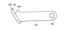
- the presser holder 142 that supports the presser portion 140 is formed of a flat plate processed into a substantially U shape in a top view, and the rear end side of the presser holder 142 is rotatably supported by a shaft 146.
- One end of the tension spring 144 is attached further behind the shaft 146 of the holding holder 142.
- the other end of the tension spring 144 is attached to the left frame 112.
- a convex portion 142a that can come into contact with the support portion 128b of the holder 128 is provided at the upper end portion on the front side of the holding holder 142.
- the first drive unit 150 includes the first motor 152, the gear 153a connected to the output shaft 152a of the first motor 152, and the like in the width direction of the housing 100.
- a pair of pinions 158, 159 provided at both ends of a shaft 156, which are first pinion portions arranged at predetermined intervals to mesh with racks 130 and 131.
- the plurality of gears 153a, 153b, 154a, 154b, and 155 form a reduction mechanism.
- the first motor 152 has an output shaft 152a and a motor body 152b, and is composed of, for example, a DC motor, a DC brushless motor, or the like.
- the driving force of the first motor 152 is transmitted to the removal unit 120 via the reduction mechanism, and the removal unit 120 is moved forward or backward.
- the first motor 152 includes a removing portion 120 when the tip portion 122s of the wedge plate main body 122a (first portion) of the removing portion 120 is in the standby position L1. In the embodiment, it is arranged below the second part.
- the lower part of the removal unit 120 means that at least a part of the first motor 152 including the output shaft 152a is located directly below the removal unit 120.
- the first motor 152 is arranged so that the output shaft 152a is parallel to or substantially parallel to the mounting surface 102a of the mounting table 102, as shown in FIGS. 2D and 3 and the like.
- the output shaft 152a of the first motor 152 is arranged so as to be orthogonal to the moving direction of the wedge plate 122 from the front to the rear (longitudinal direction of the housing 100).
- substantially parallel means to include a range slightly deviated from perfect parallelism. This range may be, for example, within ⁇ 5 °, but may be within ⁇ 10 ° depending on the required accuracy.
- the gears 153a and 153b are two-stage drive gears, and the diameter of the gear 153a is larger than the diameter of the gear 153b.
- the gear 153a is connected to the output shaft 152a of the first motor 152.
- the gear 153b meshes with the gear 154a.
- the gears 154a and 154b are two-stage drive gears, and the diameter of the gear 154a is larger than the diameter of the gear 154b.
- the gear 154a meshes with the gear 153b, and the gear 154b meshes with the gear 155.
- the right end portion of the shaft 156 extending in the width direction of the housing 100 is attached.
- a pinion 159 that meshes with the rack 131 is attached to the right end side of the shaft 156 on the gear 155 side, and a pinion 158 that meshes with the rack 130 is attached to the left end side on the opposite side.
- FIGS. 2A and 6 and the like At least a part of the paper holding mechanism 160 for holding the paper bundle P mounted on the mounting table 102 is located above the mounting table 102 and is configured to be movable. It includes a paper holding portion 170 and a second motor 192 that drives the paper holding portion 170.
- the paper holding portion 170 includes a hold lever 172 to which the parts constituting the paper holding portion are attached, a pair of paper holding racks 174 and 175 extending in the traveling direction at predetermined intervals in the width direction of the housing 100, and a mounting table. It has a paper holding plate 176 which is a holding portion for holding the paper bundle P placed on the 102.
- the hold lever 172 has a pair of flat plates 172a and 172b arranged on the rear side of the housing 100 and arranged at predetermined intervals in the width direction.
- the lower side of the flat plates 172a and 172b is arranged inside the housing 100, and the upper side thereof is arranged so as to be exposed from the mounting table 102 and is covered with the cover portion 104.
- a boss 178 projecting outward is attached to the outer surface of the flat plate 172a.
- One end of the return spring 180 composed of a tension spring is attached to the boss 178, and the other end of the return spring 180 is attached to the left frame 112.
- a boss (not shown) is attached to the outer surface of the flat plate 172b, one end of the return spring 181 is attached to this boss, and the other end of the return spring 181 is attached to the right frame 114.
- the paper holding rack 174 is provided at the lower front end of the flat plate 172a of the hold lever 172.
- the paper retainer rack 174 is substantially fan-shaped and meshes with the paper retainer pinion 198.
- the paper holding rack 175 is provided at the lower front end of the flat plate 172b of the hold lever 172.
- the paper retainer rack 175 has a substantially fan shape and meshes with the paper retainer pinion 199 of the second drive unit 190.
- the paper retainer racks 174 and 175 convert the rotational motion of the paper retainer pinions 198 and 199 into a substantially linear motion.
- the paper holding plate 176 moves toward the mounting surface 102a so that the paper bundle P does not deviate from the removal position L2 of the mounting table 102 during the removal operation of the staple S, so that the mounting table 102 It is configured so that the paper bundle P placed on the paper can be pressed.
- the paper holding plate 176 is attached to the flat plates 172a and 172b so as to be parallel to or substantially parallel to the mounting table 102. Specifically, the left side surface of the paper holding plate 176 is supported by the shaft 186, and the right side surface of the paper holding plate 176 is supported by the shaft 187.
- the second drive unit 190 includes the second motor 192, the gear 193a connected to the output shaft 192a of the second motor 192, and the housing 100.
- the plurality of gears 193a, 193b, 194a, 194b, 195 constitute a reduction mechanism.
- the second motor 192 is arranged below the removal unit 120 when it is located at the standby position L1.
- the second motor 192 has an output shaft 192a and a motor body 192b, and is composed of, for example, a DC motor, a DC brushless motor, or the like.
- the second motor 192 is driven based on an instruction from a control unit (not shown) to transmit the driving force of the second motor 192 to the paper holding unit 170 via the reduction mechanism to operate the paper holding unit 170.
- the second motor 192 is behind the first motor 152, and the tip portion 122s of the wedge plate 122 of the removing portion 120 is in the standby position L1.
- the removal unit 120 in the case is arranged below the second unit in the present embodiment.
- the lower part of the removal unit 120 means that at least a part of the second motor 192 including the output shaft 192a is located directly below the removal unit 120.
- the output shaft 192a of the second motor 192 is arranged so as to be parallel to or substantially parallel to the mounting surface 102a of the mounting table 102, as shown in FIGS. 2D and 3 and the like.
- the output shaft 192a of the motor 192 is arranged so as to be orthogonal to the moving direction of the wedge plate 122 from the front to the rear (longitudinal direction of the housing 100).
- the output shaft 192a of the second motor 192 is arranged so as to face the direction opposite to the output shaft 152a of the first motor 152.
- the output shaft 152a of the first motor 152 is arranged so as to face the right direction
- the output shaft 192a of the second motor 192 is arranged so as to face the opposite side to the left.
- the opposite direction means that the output shafts 152a and 192a are oriented 180 degrees opposite to each other and also include a range slightly deviated from the 180 degrees opposite direction. This range may be, for example, within ⁇ 5 °, but may be within ⁇ 10 ° depending on the required accuracy.
- substantially parallel means a case where the range is slightly deviated from the perfect parallel. This range may be, for example, within ⁇ 5 °, but may be within ⁇ 10 ° depending on the required accuracy.
- the gears 193a and 193b are two-stage drive gears, and the diameter of the gear 193a is larger than the diameter of the gear 193b.
- the gear 193a is connected to the output shaft 192a of the second motor 192.
- the gear 193b meshes with the gear 194a.
- the gears 194a and 194b are two-stage drive gears, and the diameter of the gear 194a is larger than the diameter of the gear 194b.
- the gear 194a meshes with the gear 193b, and the gear 194b meshes with the gear 195.
- the left end portion of the shaft 196 extending in the width direction of the housing 100 is attached.
- a paper holding pinion 198 that meshes with the paper holding rack 174 is attached to the left end side of the shaft 196 on the gear 195 side, and a paper holding pinion 199 that meshes with the paper holding rack 175 is attached to the right end side on the opposite side.
- the accommodating portion 200 is removed by the tip portion 122s of the wedge plate 122 constituting the removing portion 120 in order to be able to accommodate the staple S falling from the paper bundle P. It is located below the removal section 120 when it is at position L2. Further, the accommodating portion 200 is arranged between the flat plates 172a and 172b of the hold lever 172 constituting the paper pressing mechanism 160, and is arranged in an empty space below the pressing holder 142 constituting the staple removing mechanism 110.
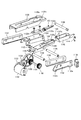
- FIG. 7 is a diagram showing an internal configuration of the staple removing device 1A including the left frame 112, the right frame 114, the front frame 116, and the rear frame 117.
- FIG. 8 is an exploded perspective view of the staple removing device 1A shown in FIG. 7.
- a left frame 112, a right frame 114, a front frame 116, and a rear frame 117 are erected on the outer peripheral portions of the staple pulling mechanism 110 and the paper holding mechanism 160 so as to surround them.
- the left frame 112 is erected on the left side of the staple removal mechanism 110.
- a guide groove 113 extending in the moving direction (longitudinal direction of the housing 100) is formed in the upper portion of the left frame 112 in front of or behind the removing portion 120.
- the guide groove 113 is a first groove 113a for locating the tip portion 122s of the wedge plate 122 of the removing portion 120 waiting at the standby position L1 below the mounting table 102, and the wedge plate 122 of the removing portion 120.
- It includes a second groove 113b for moving the tip portion 122s from the front side of the removal position L2 in a state of protruding from the mounting table 102 until it passes through the removal position L2.
- the position before the removal position L2 includes a position between the standby position L1 and the removal position L2.
- the first groove 113a is formed so that the second drive shaft 138 is closer to the mounting table 102 than the first drive shaft 136 when the tip portion 122s of the removal portion 120 is at least in the standby position L1.
- the first groove 113a extends in parallel along the mounting surface 102a of the mounting table 102 by a predetermined distance from the start end of the moving section of the removing portion 120.
- the second groove 113b is formed at a position slightly lower than the first groove 113a via the stepped portion 113c. That is, the step portion 113c connects the first groove 113a and the second groove 113b.
- the second groove 113b extends in parallel along the mounting surface 102a of the mounting table 102 from the step portion 113c to the end of the moving section of the wedge plate 122.
- the left end portions of the first drive shaft 136 and the second drive shaft 138 of the removal portion 120 are inserted into the guide groove 113.
- the removing portion 120 can be moved along the guide groove 113, and can be moved from the front and the rear along the mounting table 102.
- the right frame 114 is erected on the right side of the staple removal mechanism 110.
- a guide groove 115 extending in the moving direction (longitudinal direction of the housing 100) is formed in the upper part of the right frame 114 in front of or behind the removing portion 120.
- the guide groove 115 is a first groove 115a for locating the tip portion 122s of the wedge plate 122 of the removing portion 120 waiting at the standby position L1 below the mounting table 102, and the wedge plate 122 of the removing portion 120. It includes a second groove 115b for moving the tip portion 122s from the front side of the removal position L2 in a state of protruding from the mounting table 102 until it passes through the removal position L2.
- the second groove 115b is formed so that the second drive shaft 138 is closer to the mounting table 102 than the first drive shaft 136 when the tip portion 122s of the removal portion 120 is at least in the standby position L1.
- the second groove 115b extends in parallel along the mounting surface 102a of the mounting table 102 by a predetermined distance from the start end of the moving section of the removing portion 120.
- the second groove 115b is formed at a position slightly lower than the first groove 115a via the stepped portion 115c.
- the second groove 115b extends in parallel along the mounting surface 102a of the mounting table 102 from the step portion 115c to the end of the moving section of the wedge plate 122.
- the right end portions of the first drive shaft 136 and the second drive shaft 138 of the removal portion 120 are inserted into the guide groove 115.
- the removing portion 120 can move along the guide groove 115, and can move forward and backward along the mounting table 102. That is, the guide groove (guide portion) 115 formed in the frames 112 and 114 (support member) guides the removal portion 120 in a movable manner.
- the front frame 116 is erected on the front side of the staple removal mechanism 110, and the rear frame 117 is erected on the rear side of the paper holding mechanism 160.
- FIG. 9A is a perspective view showing the operation of the staple removing mechanism 110 at the standby position L1
- FIG. 9B is a perspective view showing the operation of the staple removing mechanism 110 moving to the removal position L2.
- FIG. 10A is a side view of the main part showing the operation of the staple removing mechanism 110 at the standby position L1
- FIG. 10B is a side view of the main part showing the operation of the staple removing mechanism 110 moving to the removal position L2.
- FIG. 11A is a side view showing the operation of the staple removing mechanism 110 at the standby position L1
- FIG. 11B is a side view of a main part showing the operation of the staple removing mechanism 110 of FIG. 11A.
- FIG. 12A is a side view showing the operation of the staple removing mechanism 110 moving to the removal position L2
- FIG. 12B is a side view of a main part showing the operation of the staple removing mechanism 110 of FIG. 12A.
- FIGS. 11 and 12 for convenience, only the left frame 112 side will be described, but the same operation as the left frame 112 side can be adopted for the right frame 114 side on the opposite side.
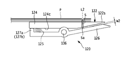
- the wedge plate 122 When the staple removing device 1A is in the standby state, the wedge plate 122 is stopped at the standby position L1 of the housing 100 as shown in FIGS. 9A, 10A and 11A. At this time, the second drive shaft 138 is located in the first groove 113a of the guide groove 113 of the left frame 112, and the first drive shaft 136 is located in the second groove 113b of the guide groove 113 of the left frame 112. Therefore, the mounting portion 122b side of the wedge plate 122 is in a raised state, and the wedge plate main body 122a side including the tip portion 122s of the wedge plate 122 is at a lower position than the mounting portion 122b side. As a result, as shown in FIG.
- the wedge plate main body 122a including the tip portion 122s of the wedge plate 122 is lower than the mounting surface 102a of the mounting base 102. Located in. As a result, when the paper bundle P is placed on the mounting table 102, it is possible to prevent the wedge plate 122 from hitting the paper bundle P and being separated from the mounting table.
- the first motor 152 When the start switch 106 of the staple removing device 1A is operated, the first motor 152 is driven as shown in FIGS. 9B and 10B, and the driving force of the first motor 152 is the plurality of gears 153a, 153b, 154a, It is transmitted to the pinions 158 and 159 via 154b and 155.
- the pinions 158 and 159 rotate clockwise in FIG. 10B, and the racks 130 and 131 meshing with the pinions 158 and 159 move from the front to the rear along the mounting table 102 so that the wedge plate 122 moves forward. Move backwards from.
- the second drive shaft 138 moves from the first groove 113a of the guide groove 113 of the left frame 112 to the second groove 113b.
- the second drive shaft 138 is parallel to and at the same height as the mounting surface 102a of the mounting base 102 with the first drive shaft 136. Therefore, when the position of the wedge plate 122 on the mounting portion 122b side is lowered, the wedge plate main body 122a side of the wedge plate 122 is lifted (rotated) with the first drive shaft 136 as a fulcrum.
- the upper surface of the wedge plate main body 122a has a structure slightly protruding from the upper surface of the mounting portion 122b, as shown in FIG.
- the tip portion 122s of the wedge plate 122 is the mounting surface of the mounting base 102. It is located above 102a. In other words, the tip portion 122s of the wedge plate 122 rotates with the drive shaft 136 as a fulcrum. In the present embodiment, the wedge plate 122 protrudes from the mounting surface 102a of the mounting table 102 through the opening 102b of the mounting table 102 from the front side of the removing position L2 until it passes through the removal position L2. Move while maintaining. As a result, the tip portion 122s of the wedge plate main body 122a is surely pushed between the paper bundle P and the crown portion Sa.
- FIG. 13A is a perspective view showing the operation of the paper holding mechanism 160 in the standby position
- FIG. 13B is a perspective view showing the operation of the paper holding mechanism 160 moving to the pressing position
- FIG. 14A is a side view of a main part showing the operation of the paper holding mechanism 160 in the standby position
- FIG. 14B is a side view of the main part showing the operation of the paper holding mechanism 160 moving to the pressing position.
- the paper holding plate 176 is stopped at a position at a certain interval from the mounting surface 102a of the mounting table 102.
- the constant interval is an interval at which the lower surface of the paper holding plate 176 does not come into contact with the uppermost layer of the paper bundle P placed on the mounting table 102.
- the second motor 192 When the start switch of the staple removal device 1A is turned on, the second motor 192 is driven. The driving force of the second motor 192 is transmitted to the paper holding pinions 198 and 199 via the gears 193a, 193b, 194a, 194b and 195. Along with this, as shown in FIGS. 13B and 14B, the paper retainer pinions 198 and 199 rotate clockwise, and the paper retainer racks 174 and 175 meshing with the paper retainer pinions 198 and 199 move substantially downward.
- the hold lever 172 rotates counterclockwise with the hold lever shaft 182 as a fulcrum against the elastic force of the return spring 180, and the paper holding plate 176 is placed on the mounting base 102. Moves (descends) in the direction approaching. As a result, the paper bundle P placed on the mounting table 102 is pressed by the paper holding plate 176 with a constant pressing force.
- the second motor 192 is driven in the reverse rotation.
- the paper holding plate 176 moves (rises) in the direction away from the paper bundle P and returns to the standby position shown in FIG. 14A or the like.
- 15A to 15G are side views showing an example of the operation of the staple removing device 1A when the staple S is pulled out from the paper bundle P.
- 16A to 16E are enlarged views of a main part showing an example of the operation of the wedge plate 122 when the staple S is pulled out from the paper bundle P.
- 17A to 17E are diagrams showing the states of the wedge plate 122 and the staple S when the staple S is pulled out from the paper bundle P. In the description of FIG. 15A and the like, for convenience, only the operation on the right side of the staple removing device 1A will be described, but the same operation as on the right side can be adopted for the opposite left side.
- the paper bundle P bound by the staple S is placed on the mounting table 102.
- the user aligns the paper bundle P with the mark indicating the removal position L2 provided on the mounting table 102, and mounts the staple S with the crown portion Sa side facing the mounting table.
- the paper bundle P is bound by staples S.
- the legs Sb and Sb of the staple S penetrate the paper bundle P in the thickness direction of the paper, are bent inward, and bite into the paper surface.
- the first motor 152 is driven.
- the pinion 159 rotates clockwise, so that the removing portion 120 including the rack 131 and the wedge plate 122 moves from the front to the rear.
- the tip portion 122s of the wedge plate main body 122a is positioned below the mounting surface 102a of the mounting base 102, as in the standby position L1. doing.
- the second drive shaft 138 of the removing portion 120 moves to the second groove 115b of the guide groove 115, so that the wedge is shown in FIG. 16B.
- the tip portion 122s of the plate 122 projects from the mounting surface 102a through the opening 102b of the mounting base 102.
- the upper surface of the wedge plate 122 comes into contact with the back surface of the bottom layer of the paper bundle P, and moves from the front to the rear while pressing the paper bundle P.
- the tip of the removing portion 120 waiting at the standby position L1 is located below the mounting table 102, and the tip of the removing portion 120 passes through the removing position from the front of the removing position. It is formed so as to protrude from the mounting table 102.
- the pressing portion 140 rises due to the urging of the tension spring 144, and comes into contact with the crown portion Sa of the paper bundle P that moves from the front to the rear by the pushing force of the wedge plate 122, so that the staple S moves to the rear. regulate.
- the thickness of the wedge plate 122 pushed between the paper bundle P and the crown portion Sa at the removal position is increased in the side view. It gets thicker. Due to the extension of the tension spring 144, the pressing portion 140 is lowered in contact with the wedge plate 122 and the crown portion Sa following the thickness direction of the wedge plate 122. As a result, as shown in FIG. 17C, the crown portion Sa is pushed by the wedge plate 122 in the direction away from the paper bundle P, and the legs Sb and Sb of the staple S bent inward with respect to the paper surface of the paper bundle P. It extends so as to be substantially orthogonal to each other. As shown in FIG.
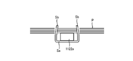
- the constricted portion 122c of the wedge plate 122 is located at the removal position L2.
- the width dimension D1 of the constricted portion 122c of the wedge plate 122 is narrower than the width dimension D3 between the leg portions Sb and Sb of the staple S that springs back, so that the leg of the staple S The portions Sb and Sb are separated from the side surface of the wedge plate 122, and the staple S falls into the accommodating portion 200.
- the first motor 152 is driven in the reverse rotation.
- the pinion 159 rotates counterclockwise, the removal unit 120 including the rack 131 and the wedge plate 122 moves from the rear to the front along the mounting table 102, and the removal unit 120 moves from the removal position L2 to the standby position. Return to L1.
- the second motor 192 is driven by the reverse rotation.
- the paper holding pinion 199 rotates counterclockwise, and the paper holding rack 175 moves substantially upward, so that the paper holding plate 176 moves away from the mounting table 102 via the hold lever 172. Return to the standby position.
- the wedge plate 122 is configured to move linearly along the mounting table 102, and the tip portion 122s of the wedge plate 122 protrudes from the mounting surface 102a of the mounting table 102. In this state, it is moved from the front of the removal position L2 until it passes through the removal position L2. That is, by providing a certain section in which the tip portion 122s of the wedge plate 122 moves in a state of protruding from the mounting surface 102a, the removal point for removing the staple S can be set as a surface instead of a point.
- the staple S of the paper bundle P in a certain range on the mounting table 102, the staple S can be removed from the paper bundle P, so that the occurrence of defects during the removal operation can be reliably prevented. Can be done. Further, since the staple S may be set in a certain range on the mounting table 102, the burden on the user when setting the paper bundle P on the mounting table 102 can be reduced.
- the tip portion 122s of the wedge plate 122 is moved for a certain section in a state of being projected from the mounting surface 102a of the mounting table 102, the tip portion 122s of the wedge plate 122 is referred to as the paper bundle P. It can be reliably inserted between the crown portion Sa.
- the tip portion 122s of the wedge plate 122 is placed on the mounting surface 102a of the mounting base 102. Since it is positioned downward, it is possible to prevent the paper or the crown portion Sa from being caught by the tip portion 122s of the wedge plate 122 when the paper bundle P is set on the mounting table 102. As a result, it is possible to avoid the occurrence of defects in the paper bundle P due to damage to the paper, and it is possible to improve the operability of the user when the paper bundle P is set on the mounting table 102.
- FIG. 18 is an exploded perspective view of the staple removing device 1B according to the second embodiment.
- a guide groove 213 extending along the mounting surface 102a of the mounting table 102 is formed on the upper part of the left frame 112.
- the guide groove 213 is formed parallel and linearly with respect to the mounting surface 102a from the start end to the end of the moving section including the standby position L1 and the removal position L2 (see FIG. 19B) of the wedge plate 122.
- the right end portions of the first drive shaft 136 and the second drive shaft 138 of the removal portion 120 are inserted into the guide groove 213.
- a guide groove 215 extending along the mounting surface 102a of the mounting table 102 is formed on the upper part of the right frame 114.
- the guide groove 215 is formed parallel and linearly with respect to the mounting surface 102a from the start end to the end of the moving section including the standby position L1 and the removal position L2 of the wedge plate 122.
- the left end portions of the first drive shaft 136 and the second drive shaft 138 of the removal portion 120 are inserted into the guide groove 215. With such a configuration, the removing portion 120 can move forward and backward along the guide grooves 213 and 215 in parallel with the mounting surface 102a of the mounting table 102.
- a step portion 122d is provided between the wedge plate main body 122a and the constricted portion 122c.
- the upper surface of the wedge plate main body 122a projects from the upper surfaces of the mounting portion 122b and the constricted portion 122c via the step portion 122d.
- elongated holes 124a and 124b through which the second drive shaft 138 is inserted are formed.
- the elongated holes 124a and 124b have a long axis extending in the vertical direction.
- the length of the major axis defines the maximum amount of protrusion of the wedge plate 122 that protrudes from the mounting surface 102a of the mounting table 102.
- the front end portion of the blade holder 124 is supported by the second drive shaft 138 and is configured to be movable in the vertical direction along the elongated holes 124a and 124b.
- the tip portion 122s of the wedge plate 122 moves in the vertical direction with the first drive shaft 136 as a fulcrum as the rear end portion of the blade holder 124 moves up and down.
- the wedge plate unit holder 230 is composed of a flat plate formed by bending in a substantially U shape, and is arranged so as to be overlapped on the side surface of the blade holder 124 from below.
- the rack 130 is arranged on the right side of the wedge plate unit holder 230, and the rack 131 is arranged on the left side thereof.
- One end of the wedge plate spring 232 was attached to the attachment portion provided on the lower surface of the front end portion of the blade holder 124, and the other end of the wedge plate spring 232 was provided on the upper surface of the front end portion of the wedge plate unit holder 230. It is attached to the attachment part. The front end of the blade holder 124 and the front end of the wedge plate unit holder 230 are urged to each other in a direction closer to the wedge plate spring 232.
- the spring constant of the wedge plate spring 232 defines the pressing force of the wedge plate 122 projecting upward from the mounting table 102 against the paper bundle P.
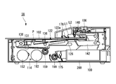
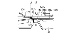
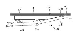
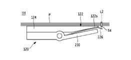
- FIG. 19A is an explanatory view of the operation of the wedge plate 122 of the staple removing device 1B at the standby position L1
- FIG. 19B is an enlarged view of a main part of the wedge plate 122 and the mounting table 102 shown in FIG. 19A
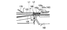
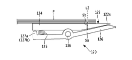
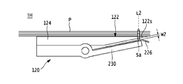
- FIG. 20A is an explanatory view of the operation of the wedge plate 122 of the staple removing device 1B that moves to the removal position L2
- FIG. 20B is an enlarged view of a main part of the wedge plate 122 and the mounting table 102 shown in FIG. 20A.
- FIGS. 19A and 20A only the operation on the left side of the staple removing device 1B will be described, but since the operation on the right side is also the same as that on the left side, detailed description thereof will be omitted.
- the tip portion 122s of the wedge plate 122 is located in the standby position L1.
- the upper surface of the wedge plate main body 122a (the tip end side of the wedge plate 122) is pushed down below the mounting table 102 by hitting the back surface of the mounting table 102.
- the rear end portion of the blade holder 124 is pushed up (rotated) along the elongated hole 124b with the first drive shaft 136 as a fulcrum.
- the first motor 152 is driven and the pinion 159 rotates via a plurality of gears 153a and the like.
- the pinion 159 rotates, the removing portion 120 including the rack 131 and the wedge plate 122 moves from the front to the rear, and as shown in FIG. 20B, the stepped portion 122d of the wedge plate 122 is placed on the mounting table 102. It comes off from the back surface of the and moves into the opening 102b.
- the front end portion of the blade holder 124 is pushed down along the elongated hole 124b by the urging of the wedge plate spring 232, while the tip end portion 122s of the wedge plate 122 is pushed up with the first drive shaft 136 as a fulcrum.
- the tip portion 122s of the wedge plate 122 protrudes from the mounting surface 102a of the mounting table 102.
- the tip portion 122s of the wedge plate 122 rotates with the drive shaft 136 as a fulcrum.
- the tip portion 122s of the wedge plate 122 moves from the front side of the removal position L2 until it passes through the removal position L2 in a state of protruding from the mounting surface 102a of the mounting table 102.
- the tip portion 122s of the wedge plate 122 is moved in a fixed section in a state of being projected from the mounting surface 102a of the mounting table 102. Therefore, the tip portion 122s of the wedge plate 122 can be reliably inserted between the paper bundle P and the crown portion Sa. Further, when the tip portion 122s of the wedge plate 122 is in the standby position L1, the tip portion 122s of the wedge plate 122 is positioned below the mounting surface 102a of the mounting table 102, so that the paper bundle P is set on the mounting table 102. At this time, it is possible to prevent the paper or the crown portion Sa from being caught by the tip portion 122s of the wedge plate 122.
- ⁇ Third embodiment> the mechanism for adjusting the moving height of the wedge plate 122 is different from that of the above embodiment. Since the configuration and operation of the other staple removing device 1C are the same as those of the staple removing device 1A of the first embodiment, detailed description of the common parts will be omitted.
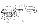
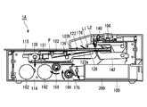
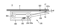
- FIG. 21 is a side view of the staple removing device 1C according to the third embodiment.
- a guide groove 313 extending along the mounting surface 102a of the mounting table 102 is formed on the upper part of the left frame 112.
- the guide groove 313 is inclined at a constant angle so as to gradually approach the mounting table 102 from the start end to the end of the moving section of the wedge plate 122. More specifically, in the guide groove 313, the tip portion 122s of the wedge plate 122 is located below the mounting surface 102a of the mounting base 102 when the tip portion 122s of the wedge plate 122 is stopped at the standby position L1. ,
- the tip portion 122s of the wedge plate 122 is formed in a groove shape protruding from the mounting surface 102a of the mounting table 102 when passing through the removal position L2 from the front of the removal position L2.
- the upper part of the right frame 114 is also formed with a guide groove that inclines at a constant angle so as to gradually approach the mounting table 102 from the start end to the end of the moving section of the wedge plate 122. .. Since the guide groove of the right frame 114 is symmetrical with the guide groove 313 of the left frame 112 and has the same configuration, detailed description thereof will be omitted. In this way, in the guide groove 313, the tip of the removing portion 120 waiting at the standby position L1 is located below the mounting table 102, and the tip of the removing portion 120 passes through the removing position from the front of the removing position. It is formed so as to protrude from the mounting table 102.
- FIG. 22A is an explanatory view of the operation of the wedge plate 122 of the staple removing device 1C at the standby position L1
- FIG. 22B is an enlarged view of a main part of the wedge plate 122 and the mounting table 102 shown in FIG. 22A
- FIG. 23A is an explanatory view of the operation of the wedge plate 122 of the staple removing device 1C that moves to the removal position L2
- FIG. 23B is an enlarged view of a main part of the wedge plate 122 and the mounting table 102 shown in FIG. 23A.
- FIGS. 22A and 23A only the operation on the right side of the staple removing device 1C will be described, but since the operation on the left side is also the same as that on the right side, detailed description thereof will be omitted.
- the tip portion 122s of the wedge plate 122 When the staple removing device 1C is in the standby position, as shown in FIGS. 22A and 22B, the tip portion 122s of the wedge plate 122 is located in the standby position L1, and the second drive shaft 138 of the removing portion 120 is the left frame 112. It is located at the starting end of the guide groove 113. In this case, the tip portion 122s of the wedge plate 122 is located below the mounting surface 102a of the mounting table 102. As a result, when the paper bundle P is placed on the mounting table 102, it is possible to prevent the wedge plate 122 from hitting the paper bundle P and causing a problem.
- the first motor 152 When the staple removal device 1C is activated, the first motor 152 is driven as shown in FIGS. 23A and 23B. The driving force of the first motor 152 is transmitted to the pinion 158 via the gear 153a and the like. Along with this, the pinion 158 rotates clockwise to move the rack 130 from the front to the rear, and the wedge plate 122 to move from the front to the rear along the guide groove 313 of the left frame 112. The wedge plate 122 gradually moves toward the mounting table 102 along the guide groove 313, and the tip portion 122s protrudes from the mounting table 102. In another embodiment 2, the tip portion 122s of the wedge plate 122 protrudes from the mounting surface 102a of the mounting table 102 from the front of the removing position L2, and maintains the protruding state until it passes through the removing position L2.
- the tip portion 122s of the wedge plate 122 is moved in a fixed section in a state of protruding from the mounting surface 102a of the mounting table 102. Therefore, the tip portion 122s of the wedge plate 122 can be reliably inserted between the paper bundle P and the crown portion Sa. Further, when the tip portion 122s of the wedge plate 122 is in the standby position L1, the tip portion 122s of the wedge plate 122 is positioned below the mounting surface 102a of the mounting table 102, so that the paper bundle P is set on the mounting table 102. At this time, it is possible to prevent the paper or the crown portion Sa from being caught by the tip portion 122s of the wedge plate 122.
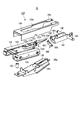
- FIG. 24 is an exploded perspective view of the staple removing device 1D according to the fourth embodiment.
- Guide pin mounting portions 410, 411 to which the guide pins 420, 421 are mounted are provided on the lower surface of the mounting table 102 on the rear end side.
- the guide pin mounting portions 410 and 411 are arranged at predetermined intervals in the width direction, specifically, at substantially the same interval as between the left frame 112 and the right frame 114.
- the guide pin mounting portion 410 is formed with a pin opening 410a
- the guide pin mounting portion 411 is formed with a pin opening 411a.
- the pin openings 410a and 411a are formed of elongated holes having a long axis extending in the vertical direction.
- Shaft mounting portions 408 and 409 through which the fulcrum shaft 418 is inserted are provided on the lower surface on the rear end side of the mounting base 102.
- the shaft mounting portions 408 and 409 are arranged at predetermined intervals in the width direction, specifically, at substantially the same interval as between the left frame 112 and the right frame 114.
- the shaft mounting portion 408 is formed with a shaft opening 408a
- the shaft mounting portion 409 is formed with a shaft opening 409a.
- a recess 112d in which the mounting base spring 416 is arranged is provided at a position facing the guide pin mounting portion 410 on the rear end side of the left frame 112.
- a recess 114d in which the mounting base spring 417 is arranged is provided at a position facing the guide pin mounting portion 411 on the rear end side of the right frame 114.
- the guide grooves 413 formed in the left frame 112 and the guide grooves 415 formed in the right frame 114 have the same configurations and functions as those of the guide grooves 213 and 215 of the second embodiment. Omit.
- the guide pin 420 is inserted into the pin opening 410a on the front end side of the mounting table 102 from the outside, and is attached to the opening 112e of the left frame 112 arranged inside the guide pin 420.
- the guide pin 421 is inserted into the pin opening 411a on the front end side of the mounting table 102 from the outside, and is attached to the opening 114e of the right frame 114 arranged inside the guide pin 421.
- a mounting table spring 416 is arranged between the recess 112d of the left frame 112 and the lower surface of the mounting table 102.
- the mounting base spring 417 is arranged between the recess 114d of the right frame 114 and the lower surface of the mounting base 102.
- the fulcrum shaft 418 is inserted through the opening 112f of the left frame 112, the shaft openings 408a and 409a of the mounting table 102, and the opening 114f of the right frame 114.
- the mounting table 102 can move in the vertical direction along the pin openings 410a and 411a on the rear end side with the fulcrum shaft 418 on the front end side as the fulcrum. That is, the mounting table 102 moves in the vertical direction relative to the tip portion 122s of the wedge plate 122 with the fulcrum shaft 418 as the fulcrum within the range of the length of the elongated holes of the pin openings 410a and 411a.
- FIG. 25A is an explanatory view of the operation of the wedge plate 122 of the staple removing device 1D at the standby position L1
- FIG. 25B is an enlarged view of a main part of the wedge plate 122 and the mounting table 102 shown in FIG. 25A
- FIG. 26A is an explanatory view of the operation of the wedge plate 122 of the staple removing device 1D that moves to the removal position L2
- FIG. 26B is an enlarged view of a main part of the wedge plate 122 and the mounting table 102 shown in FIG. 26A.
- FIGS. 25A and 26A only the operation on the right side of the staple removing device 1C will be described, but since the operation on the left side is also the same as that on the right side, detailed description thereof will be omitted.
- the paper retainer plate 176 of the paper retainer mechanism 160 is stopped at the standby position at a certain interval from the mounting table 102.
- the mounting table 102 is urged upward by the mounting table spring 416, so that the tip portion 122s of the wedge plate 122 is located below the mounting table 102.
- the second motor 192 is driven, and the paper holding plate 176 descends toward the mounting table 102 via the gear 153a or the like, and is placed on the mounting table 102.
- the paper bundle P is pressed by the paper holding plate 176.
- the mounting table 102 is pressed by the paper holding plate 176 via the paper bundle P, so that the mounting table spring 416 is compressed and the mounting table 102 has an elongated pin opening. It is pushed down along the portion 410a (see FIG. 24) and the like. As a result, the tip portion 122s of the wedge plate 122 protrudes from the mounting surface 102a of the mounting table 102.
- the mounting table 102 is restricted from moving downward by contacting the flanges formed at the upper ends of the left frame 112 and the right frame 114. Therefore, by adjusting the height of the flange, the maximum amount of protrusion of the tip portion 122s of the wedge plate 122 can be adjusted. Further, the spring constants and sizes of the mounting base springs 416 and 417 may be adjusted.
- the tip portion 122s of the wedge plate 122 is moved in a fixed section in a state of being projected from the mounting surface 102a of the mounting table 102. Therefore, the tip portion 122s of the wedge plate 122 can be reliably inserted between the paper bundle P and the crown portion Sa. Further, when the tip portion 122s of the wedge plate 122 is in the standby position L1, the tip portion 122s of the wedge plate 122 is positioned below the mounting surface 102a of the mounting table 102, so that the paper bundle P is set on the mounting table 102. At this time, it is possible to prevent the paper or the crown portion Sa from being caught by the tip portion 122s of the wedge plate 122.
- ⁇ Modification 1-1> In the staple removing device 1E according to the modified example 1-1, an embodiment shown in FIG. 1A or the like is provided in that a crown support portion 500 for supporting the crown portion Sa is provided between the staple plate S and the wedge plate 122E when the staple S is removed. Is different from.
- the components that are substantially the same as the staple removing device 1A and the like are designated by the same reference numerals, so that duplicate description will be omitted.
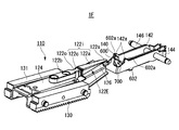
- FIG. 27A is an exploded perspective view of the staple removing device 1E according to the modified example 1-1
- FIG. 27B is a perspective view of the staple removing device 1E.
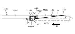
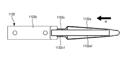
- FIG. 28 is a side view of the wedge plate 122E according to the modified example 1-1.
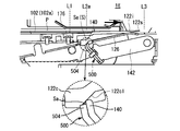
- FIG. 29A is a side view of the crown support portion 500 and the pressing portion 140 according to the modified example 1-1
- FIG. 29B is a diagram illustrating a state in which the crown portion Sa is supported by the crown supporting portion 500 and the pressing portion 140.
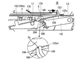
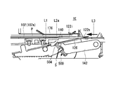
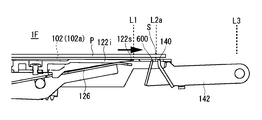
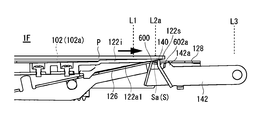
- the staple removing device 1E can place the paper bundle P bound by the staples S including the crown portion Sa and the pair of leg portions Sb with the crown portion Sa facing downward.
- the mounting table 102 (see FIG. 1A) and the tip portion 122s are removed from the standby position (first position) L1 along the mounting table 102 via the removal start position (second position) L2a (third position). It is movable to L3, and when it moves from the standby position L1 to the removal start position L2a, it is inserted between the paper bundle P and the staple S, and further moves from the removal start position L2a toward the removal completion position L3.
- An inclined portion 122i that starts pulling out the staple S from the bundle P, and a crown portion Sa of the staple S that is pulled out from the paper bundle P by the inclined portion 122i and is engaged (hooked or wound) with the inclined portion 122i.
- the pressing portion (regulating portion) 140 that regulates the movement of the staple S together with the inclined portion 122i in the direction of the removing completion position L3 by contacting the staple S from the removal complete position L3 side, and the pressing portion 140 restrict the movement of the staple S.
- a crown support portion 500 located below the crown portion Sa of the staple S is provided.
- the standby position L1 is the position of the tip portion 122s at the initial position where the inclined portion 122i is stopped before starting the removal operation.
- the removal start position L2a is a position where the tip portion 122s of the inclined portion 122i is inserted between the paper bundle P on the mounting table 102 and the staple S (crown portion Sa), in other words, on the mounting table 102. This is the position of the staple S (crown portion Sa) of the paper bundle P placed on the paper bundle P.
- the removal completion position L3 is the position of the tip portion 122s of the inclined portion 122i when the staple S is completely removed from the paper bundle P by the inclined portion 122i (the staple S is completely separated from the paper bundle P).
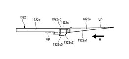
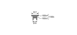
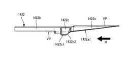
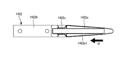
- the wedge plate 122E includes an inclined portion 122i and a mounting portion 122b.
- the inclined portion 122i has a wedge plate main body 122a and a constricted portion 122c, includes a base end portion 122o and a tip portion 122s, and is inclined so that the thickness becomes thinner from the base end portion 122o to the tip end portion 122s.
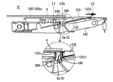
- the inclined surface 122ac has a first inclined surface 122a1 and a second inclined surface 122c1.
- the inclined portion 122i is located between the removal start position L2a and the removal completion position L3, and faces the inclined surface 122ac while the tip portion 122s moves from the removal start position L2a to the removal completion position L3.
- the first inclined surface 122a1 is a surface inclined at an angle ⁇ 1 with respect to a virtual surface (horizontal plane) VP parallel to the upper surface of the wedge plate main body 122a.
- the second inclined surface 122c1 is a surface inclined at an angle ⁇ 2 with respect to the virtual surface (horizontal plane) VP parallel to the upper surface of the wedge plate main body 122a.
- the first inclined surface 122a1 and the second inclined surface 122c1 are each composed of continuous surfaces, but are not necessarily limited to continuous surfaces, and are intermittent surfaces, specifically, a plurality of surfaces having different angles. It can also be configured with an inclined surface of.
- the second inclined surface 122c1 of the constricted portion 122c with respect to the virtual surface VP is larger than the first inclined surface 122a1 of the wedge plate main body 122a with respect to the virtual surface VP.
- the angle ⁇ 2 formed by the virtual surface VP and the second inclined surface 122c1 is configured to be larger than the angle ⁇ 1 formed by the virtual surface VP and the first inclined surface 122a1 of the wedge plate main body 122a.
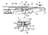
- the angle ⁇ 1 of the first inclined surface 122a1 of the wedge plate body 122a is small and long in the front-rear direction. Is set longer.
- the leg portion Sb of the staple S is completely or almost pulled out from the paper bundle P, and the load applied to the constricted portion 122c is small, so that the first of the constricted portions 122c
- the angle ⁇ 2 of the inclined surface 122a1 is set to be large and short in the front-rear direction.
- the first inclined surface 122a1 and the second inclined surface 122c1 are formed by different inclination angles. Therefore, as shown in FIG. 27A, the first inclined surface 122a1 has the first inclined surface.
- the crown portion Sa is supported by the linear crown holder 126 arranged along the 122a1.
- the crown holder 126 cannot support the crown portion Sa on the second inclined surface 122c1.
- the crown support portion 500 is provided so that a stable posture can be maintained on the inclined portion 122i until the staple S pulled out from the paper bundle P falls into the accommodating portion 200. ing.
- the crown support portion 500 is arranged at a position adjacent to the removal start position L2a side (left side in the drawing in FIG. 30A) with respect to the pressing portion 140, and is a crown portion of the staple S. Sa can be supported from the lower side.
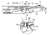
- the crown support portion 500 has a mounting portion 502 fixed to the pressing portion 140 and a support portion 504 capable of contacting the crown portion Sa of the staple S.
- the mounting portion 502 is composed of a flat plate having a substantially rectangular shape in a plan view, and is mounted on the front surface of the holding portion 140 on the removal start position L2a side by a screw or the like. In the present embodiment, the mounting portion 502 is mounted in contact with the pressing portion 140, but the present invention is not limited to this. For example, if the gap is less than the thickness of the crown portion Sa (diameter of the staple S), the mounting portion 502 may be arranged apart from the pressing portion 140.
- the support portion 504 projects convexly from the upper end portion of the mounting portion 502 toward the wedge plate 122E side, and the tip end side thereof is configured in a tapered shape.
- the tip end side of the support portion 504 By forming the tip end side of the support portion 504 into a tapered shape, the tip end side can be supported in a state of being abutted against the crown portion Sa, so that the posture of the staple S can be stabilized.
- the shape of the tip side of the support portion 504 may be, for example, a configuration in which a plurality of tapered shapes are provided along the longitudinal direction of the crown portion Sa, or an arc shape or a rectangular shape. You may.
- the support portion 504 may be arranged at a predetermined interval with respect to the crown portion Sa while the pressing portion 140 restricts the staple S from moving to the removal completion position L3 side as the inclined portion 122i advances. .. That is, when the posture of the staple S during the removal operation is unstable, for example, when only one leg Sb of the staple S caught on the inclined portion 122i comes off and the staple S rotates, the tip side of the support portion 504 becomes a crown. It may be configured so as to abut against the portion Sa so that the posture of the staple S can be stabilized.
- the predetermined interval is an interval at which at least the tip end side of the support portion 504 can contact and support the crown portion Sa even when the staple S caught on the inclined portion 122i is in an unstable posture. is there.
- the tip portion of the support portion 504 enables the crown portion Sa to be supported between the support portion 504 and the inclined portion 122i, and holds the crown portion Sa that is about to move to the removal completion position L3 side on the front surface of the holding portion 140.
- the crown portion Sa is formed at a position lower than the tip surface 140a of the pressing portion 140 by at least the thickness T1 of the crown portion Sa.
- the length of the support portion 504 in the front-rear direction is composed of the thickness T2 or more of the crown portion Sa.
- the tip side of the support portion 504 of the crown support portion 500, the front surface of the pressing portion 140, and the lower surface of the inclined portion 122i (first inclined surface 122a1) are formed by the crown portion Sa when the staple S is removed. Can be reliably supported.
- the length of the support portion 504 in the front-rear direction is not limited to the thickness T2 or more of the crown portion Sa, and may be less than the thickness T2 of the crown portion Sa as long as a part of the crown portion Sa can be supported.
- a position regulating portion 506 projecting toward the pressing portion 140 is provided.
- the position regulating portion 506 engages with the lower end portion of the pressing portion 140, and functions as a positioning portion when the mounting portion 502 and the supporting portion 504 are attached to the pressing portion 140.
- FIG. 29C is a side view of the case where the crown support portion 500 and the pressing portion 140 are composed of one component. As shown in FIG. 29C, the upper end side of the pressing portion 140 is cut out so as to have a tapered shape shown in FIG. 27A, for example, so that the crown supporting portion 500 can function as supporting the crown portion Sa.
- FIGS. 30A to 30F are side views showing the operation of the staple removing device 1E when the staple S is pulled out from the paper bundle P.
- the paper bundle P When the paper bundle P is placed on the mounting table 102 by the user and the start switch 106 (see FIG. 1A) of the staple removing device 1E is pressed, the paper bundle P is moved by the paper holding plate 176 as shown in FIG. 30A. It is pressed and the paper bundle P is pressed against the mounting table 102.
- the pressing portion 140 abuts on the surface on the removal complete position L3 side of the crown portion Sa that moves from the front to the rear by the pushing force of the inclined portion 122i, and the staple S moves to the rear removal complete position L3 side together with the wedge plate body 122a. Regulate what you do. That is, the holding portion 140 does not move the staple S from the removal start position L2a to the removal completion position L3 side due to the sliding operation of the wedge plate main body 122a inserted between the staple S and the paper bundle P during the removal operation. As described above, the crown portion Sa is pressed from the removal completion position L3 side. Further, in this modification, the support portion 504 of the crown support portion 500 abuts on the lower surface of the crown portion Sa, so that the posture stability of the staple S is ensured.
- the thickness of the inclined portion 122i including the first inclined surface 122a1 inserted between the paper bundle P and the crown portion Sa becomes thicker, as shown in FIG. 30C, the pressing portion 140 and the crown portion 140 and the crown.
- the support portion 500 is lowered by the tension spring 144 following the thickness direction of the inclined portion 122i in a state of being in contact with the inclined portion 122i and the crown portion Sa.
- the crown portion Sa is supported by the support portion 504 and the pressing portion 140 of the crown support portion 500.
- the staple S when the staple S is located on the second inclined surface 122c1 of the inclined portion 122i, the staple S is not supported by the crown holder 126, but the crown portion is provided by the support portion 504 and the holding portion 140 of the crown support portion 500. The state in which Sa is supported is maintained, and tilting, rotation, etc. of the staple S are prevented.
- the tip portion 122s moves to the removal completion position L3 as the wedge plate 122E advances and the staple S is located at the constricted portion 122c having the thickest thickness in the inclined portion 122i, the second portion Similar to the inclined surface 122c1, the staple S is not supported by the crown holder 126, but the crown portion Sa is supported by the support portion 504 and the pressing portion 140 of the crown support portion 500, and the posture stability of the staple S is ensured. ..
- the wedge plate 122E including the inclined portion 122i moves from the rear to the front of the removal completion position L3 along the mounting table 102 and returns to the standby position L1.
- the staple S moves forward with respect to the crown support portion 500, so that the crown portion Sa is disengaged from the support of the support portion 504.
- the staple S falls into the accommodating portion 200.
- the crown portion Sa of the staple S can be supported by the crown support portion 500 until just before the staple S falls, so that the posture stability of the staple S can be ensured until just before the staple S is dropped.
- the staple S can be reliably dropped into the accommodating portion 200, and the staple S can be prevented from scattering into the staple removing device 1E.
- the staple contact portion for peeling the staple S remaining on the inclined portion 122i of the wedge plate 122E from the inclined portion 122i when the staple S is removed from the paper bundle P It differs from the embodiment shown in FIG. 1A and the like in that 600 is provided.
- the components that are substantially the same as the staple removing device 1A and the like are designated by the same reference numerals, so that duplicate description will be omitted.
- the duplicate description is omitted by assigning the same reference numerals to the components common to the modified example 1-1. ..
- FIG. 31A is an exploded perspective view of the staple removing device 1F according to the modified example 1-2
- FIG. 31B is a perspective view of the staple removing device 1F
- FIG. 32 is a side view of the staple contact portion 600 (contact portion) and the pressing portion 140 according to the modified example 1-2.
- the staple removing device 1F includes a mounting table 102 on which a paper bundle P bound by staples S including a crown portion Sa and a pair of leg portions Sb is placed, and a tip portion 122s. Is movable along the mounting table 102 between the standby position (first position) L1 and the removal completion position (third position) L3 via the removal start position (second position) L2a, and the tip portion 122s. Is inserted between the paper bundle P and the staple S when it moves from the standby position L1 to the removal start position L2a, and further moves from the removal start position L2a toward the removal completion position L3 to move the paper bundle P to the staple S.
- the first portion is located between the inclined portion 122i including the wedge plate main body 122a for starting the pulling out and the standby position L1 and the removal start position L2a, and while the tip portion 122s moves from the removal completion position L3 to the removal start position L2a.
- a staple contact portion 600 that faces the inclined surface 122a1 and is pulled out from the paper bundle P by the inclined portion 122i and abuts on the crown portion Sa of the staple S that is engaged with the inclined portion 122i from the standby position L1 side is provided.
- the staple removing device 1F keeps the staple contact portion 600 within a predetermined value from the first inclined surface 122a1 and the second inclined surface 122c1 while the tip portion 122s moves from the removal completion position L3 to the removal start position L2a.
- a holding member (holding portion) 602 that movably supports the staple contact portion 600 so as to hold the staple contact portion 600 is provided.
- the staple removal device 1F is located between the removal start position L2a and the removal completion position L3, and faces the inclined surface 122ac while the tip portion 122s moves from the removal start position L2a to the removal completion position L3.
- the staple S is pulled out from the paper bundle P by the inclined portion 122i and abuts on the crown portion Sa of the staple S engaged with the inclined portion 122i from the removal complete position L3 side, so that the staple S is brought into contact with the inclined portion 122i in the removal complete position L3 direction.
- a holding unit (regulating unit) 140 for restricting movement is provided.
- the staple contact portions 600 are arranged to face each other in front of the standby position L1 side of the pressing portion 140 with a predetermined interval, and are arranged from the front upper end portion of the holding member 602 to the inclined portion 122i side. It projects convexly toward.
- the staple contact portion 600 is urged toward the inclined portion 122i by the tension spring 604 so that the staple plate 122E can come into contact with the lower surface of the inclined portion 122i. As shown in FIG.
- the staple contact portion 600 is inclined in a direction approaching the pressing portion 140 side toward the inclined portion 122i side (upper side), and the staple contact portion 600 is retracted when the wedge plate 122E is retracted. It is configured so that the staple S remaining engaged with the 600 can maintain the engaged state with the crown portion Sa until it separates from the inclined portion 122i.
- the staple contact portion 600 does not necessarily have to be tilted, and may be extended in the vertical (vertical) direction, for example.
- the height of the staple contact portion 600 is set to a position slightly lower than that of the pressing portion 140, for example, in consideration of the inclination angle of the first inclined surface 122a1 on the lower surface side of the inclined portion 122i.
- the width of the staple contact portion 600 is selected to be a length that can be contacted with the crown portion Sa that moves from the rear to the front as the wedge plate 122E retracts and can be inserted into the groove portion 126a of the crown holder 126. Will be done.
- the holding member 602 is formed of a flat plate processed into a substantially U shape in a top view, and is arranged so as to abut against the outside of the holding holder 142.
- the rear end side of the holding member 602 is rotatably supported by a shaft 146.
- One end of the tension spring 604 is attached further behind the shaft 146 of the holding member 602.
- the other end of the tension spring 604 is attached, for example, to the left frame 112 (see FIG. 8).
- a pair of convex portions 602a that can come into contact with the support portion 128b of the holder 128 are provided at the front upper end portion of the holding member 602.
- the area surrounded by the pressing portion 140, the staple contact portion 600, and the holding member 602 is formed when the staple S peeled off from the inclined portion 122i by the staple contact portion 600 falls.
- the opening 700 is located above the accommodating portion 200 (see FIG. 3).
- the staple S pulled out from the paper bundle P by advancing the wedge plate 122E falls into the accommodating portion 200 through the opening 700 without being caught by the inclined portion 122i. .. That is, the staple S falls into the accommodating portion 200 without using the staple contact portion 600.
- FIGS. 33A to 33G are side views showing the operation of the staple removing device 1F when the staple S is pulled out from the paper bundle P.
- the convex portion 142a of the holding holder 142 and the convex portion 602a of the holding member 602 come off from the holder 128, and the holding portion 140 and the staple contact with each other.
- the portion 600 is urged toward the upper inclined portion 122i by the tension springs 144 and 604.
- the pressing portion 140 abuts on the rear surface on the removal complete position L3 side of the crown portion Sa that moves from the front to the rear by the pushing force of the wedge plate 122E, and the staple S together with the wedge plate main body 122a is on the rear removal complete position L3 side. Regulate moving to.
- the staple contact portion 600 abuts on the first inclined surface 122a1 on the lower surface side of the inclined portion 122i.
- the pressing portion 140 and the staple contact portion 600 are pulled.
- the springs 144 and 604 lower the inclined portion 122i in contact with the inclined portion 122i and the crown portion Sa in the thickness direction of the inclined portion 122i.
- the leg portion Sb rises with respect to the paper bundle P and is pulled out from the paper bundle P, and as shown in FIG. 33D, the tip portion 122s of the inclined portion 122i
- the staple S is moved to the removal completion position L3 and the staple S is located at the constricted portion 122c which is the thickest portion of the inclined portion 122i, the removal of the staple S from the paper bundle P is completed.
- the staple S remains caught on the side surface of the inclined portion 122i due to the springback of the leg portion Sb, and does not fall into the accommodating portion 200.
- the wedge plate 122E including the inclined portion 122i in the state where the staple S is caught moves from the rear removal completion position L3 to the front standby position L1 along the mounting table 102.
- the staple contact portion 600 located in front of the staple S is in the standby position on the crown portion Sa of the staple S that is pulled out from the paper bundle P by the wedge plate 122E and remains engaged with the constricted portion 122c, for example. Contact from the L1 side.
- the removal completion position L3 It may be configured to abut in a part of the section between the removal start position L2a.
- the staple S is held by the constricted portion 122c of the inclined portion 122i by the springback of the legs Sb and Sb of the staple S expanded by inserting the wedge plate 122E. It became easy to attach, and the staple S sometimes did not fall from the inclined portion 122i. In the same case, even when the center of the inclined portion 122i in the left-right direction and the center of the crown portion Sa in the longitudinal direction are set to be misaligned, the staple S is irregularly deformed and the wedge plate 122E is set. In some cases, the staple S did not fall from.
- the staple S pulled out from the paper bundle P remains on the inclined portion 122i, the crown portion Sa is caught on the staple contact portion 600 when the wedge plate 122E is retracted. Therefore, the staple S can be reliably peeled off from the inclined portion 122i and removed. As a result, clogging of the staple S can be prevented, and the occurrence of defects during the removal operation can be suppressed.
- the staple contact portion 600 is necessarily brought into contact with the lower surface of the inclined portion 122i.
- the staple contact portion 600 may be arranged at a predetermined interval (predetermined value) with respect to the lower surface of the inclined portion 122i.
- the predetermined interval is, for example, an interval at which the staple contact portion 600 can be hooked on the crown portion Sa of the staple S remaining on the inclined portion 122i when the wedge plate 122E returns to the standby position L1.
- the staple removing device 1G according to the modified example 1-3 is configured by combining the crown support portion 500 of the modified example 1-1 and the staple contact portion 600 of the modified example 1-2. It has substantially the same functional configuration as the staple removing device 1A according to the embodiment shown in FIG. 1A and the like, the staple removing device 1E according to the modified example 1-1, and the staple removing device 1F according to the modified example 1-2. Duplicate explanations will be omitted by assigning the same reference numerals to the components.
- FIG. 34A is an exploded perspective view of the staple removing device 1G according to the modified example 1-3
- FIG. 34B is a perspective view of the staple removing device 1G.
- the staple removing device 1G holds the mounting base 102, the wedge plate 122E including the inclined portion 122i, the holding portion 140, the crown support portion 500, and the staple contact portion 600.
- the crown support portion 500 is located below the crown portion Sa of the staple S while the pressing portion 140 regulates the movement of the staple S.
- the crown support portion 500 has a mounting portion 502 fixed to the pressing portion 140 and a support portion 504 capable of contacting the crown portion of the staple S.
- the mounting portion 502 is formed of a flat plate having a substantially rectangular shape in a plan view, and is mounted on the front surface of the holding portion 140 by a screw or the like.
- the support portion 504 projects convexly from the upper end portion of the mounting portion 502 toward the inclined portion 122iE side, and the tip end side thereof is formed in a tapered shape.
- the staple contact portion 600 is located between the standby position L1 and the removal start position L2a, and while the tip portion 122s moves from the removal completion position L3 to the removal start position L2a. It faces the first inclined surface 122a1 and is pulled out from the paper bundle P by the inclined portion 122i, and comes into contact with the crown portion Sa of the staple S engaged with the inclined portion 122i from the standby position L1 side.
- the staple contact portion 600 is arranged to face the holding portion 140 and the crown support portion 500 at predetermined intervals, and protrudes from the front upper end portion of the holding member 602 toward the inclined portion 122i side.
- the area surrounded by the crown support portion 500, the staple contact portion 600, and the holding member 602 is an opening 700 through which the staple S peeled off from the inclined portion 122i at the staple contact portion 600 passes when falling. ..
- the tip end side of the crown holder 126 is in contact with the lower surface of the wedge plate 122 due to the bias of the spring 125, and the tip end portion of the wedge plate 122.
- the 122s and the tip end side of the crown holder 126 are in a closed state.
- the crown portion Sa of the staple S is inserted between the wedge plate 122 and the crown holder 126, as shown in FIG. 35B.
- the tip end side of the crown holder 126 is pushed away from the wedge plate 122 against the elastic force of the spring 125, and is opened by the opening amount W1 with respect to the tip end portion 122s of the wedge plate 122.
- the removing portion 120 further moves from the front to the rear, as shown in FIG. 35C, the thickness of the wedge plate 122 between the paper bundle P and the crown portion Sa gradually increases, and the leg portion Sb of the staple S becomes thicker. Stands away from the paper surface of the paper bundle P.
- the load of the spring 125 is set according to the staple S having a small wire diameter, the staple S can be slid while being sandwiched between the wedge plate 122 and the crown holder 126, and can be slid together with the wedge plate 122 from the front. It does not move backwards.
- 36A to 36C are schematic views showing an operation example of the removing unit 120 when the staple S is removed from the paper bundle P bound by the (thick) staple S having a large wire diameter.
- the wedge plate 122 and the blade holder 124 are shown integrally for convenience.
- the tip end side of the crown holder 126 is in contact with the lower surface of the wedge plate 122 due to the urging of the spring 125, and the tip end portion 122s of the wedge plate 122 and the tip end side of the crown holder 126 are closed. Is.
- the crown portion Sa of the staple S is inserted between the wedge plate 122 and the crown holder 126, as shown in FIG. 36B.
- the tip end side of the crown holder 126 is pushed in a direction away from the wedge plate 122 against the elastic force of the spring 125, and is opened by the opening amount W2 with respect to the tip end portion 122s of the wedge plate 122.
- the opening amount W2 corresponds to the preset value set in advance, and is an opening amount that can be held with an optimum load without opening the crown holder 126 too much when, for example, a staple S having a large wire diameter is inserted.
- the regulating portions 127a and 127b are in contact with the lower surface 124c of the blade holder 124, and the tip side of the crown holder 126 is not opened by the opening amount W2 or more. Is regulated by.
- the load of the spring 125 is set according to the staple S having a small wire diameter, and the crown holder 126 is prevented from opening more than the set value by using the regulating portions 127a and 127b. It is configured in.
- the crown holder 126 can prevent the crown holder 126 from opening more than the set value by the regulating portions 127a and 127b, and the crown portion Sa can be prevented by the constant load of the crown holder 126.
- the crown portion Sa can be pressed by the optimum load by the crown holder 126 by the spring 125 set according to the staple S having a small wire diameter. As a result, it is possible to prevent defective removal such as the paper being torn due to the crown portion Sa being dragged by moving from the front to the rear of the wedge plate 122 or the like. Therefore, according to the present embodiment, even when various types of staples S such as staples S having a large wire diameter and staples S having a small wire diameter are used, the staples S can be reliably removed from the paper bundle P. .. Further, since it is not necessary to change the removal operation or the removal mechanism according to the type of staple S, it is possible to improve the efficiency of the removal operation and reduce the cost of the apparatus.
- ⁇ Modification 2-1> the configuration of the crown holder 226 and the like are different from the configuration and the like of the crown holder 126 of the first embodiment. Since other configurations and operations of the staple removing device 1H of the modified example 2-1 are the same as those of the first embodiment, detailed description thereof will be omitted.
- FIG. 37A to 37C are schematic views of a removing portion 120 including a crown holder 226 of the staple removing device 1H according to the modified example 2-1.
- the wedge plate 122 and the blade holder 124 are shown integrally for convenience. Further, in the following, it is assumed that the staple S having a large wire diameter is used and the opening amount W2 is set to the wire diameter of the staple S used.
- the removing portion 120 constituting the staple removing device 1H includes a wedge plate 122, a blade holder 124, a crown holder 226, and a crown holder stopper 230.
- the crown holder 226 is composed of, for example, a leaf spring, and holds the crown portion Sa inserted between the wedge plate 122 and the crown holder 226.
- the base end portion of the crown holder 226 is attached to a substantially central portion of the crown holder stopper 230.
- the tip end side of the crown holder 226 is urged toward the wedge plate 122 side and is pressed against the lower surface of the wedge plate 122.
- the load of the crown holder 226 is set according to the staple S having a smaller wire diameter among the staples S to be used.
- the crown holder stopper 230 is arranged below the crown holder 226, and regulates the opening amount of the crown holder 226 so that the crown holder 226 does not open more than the set value with respect to the wedge plate 122.
- the tip end side of the crown holder 226 is arranged at a certain distance from the lower surface of the wedge plate 122 facing the crown holder 226.
- the constant interval is an interval obtained by adding the thickness of the crown holder 226 and the wire diameter of the crown portion Sa.
- the base end side of the crown holder stopper 230 is in contact with the lower surface of the blade holder 124.
- the tip end side of the crown holder 226 is pressed against the lower surface of the wedge plate 122 before the wedge plate 122 of the removal portion 120 reaches the removal position L2.
- the tip portion 122s of the wedge plate 122 is inserted between the paper bundle P and the crown portion Sa of the staple S. ..
- the crown holder 226 moves in a direction away from the lower surface of the wedge plate 122 against the elastic force, and opens by an opening amount W2 according to the wire diameter of the crown portion Sa.
- the tip end side of the crown holder 226 does not open more than the opening amount W2.
- the opening amount of the crown holder 226 is regulated by the crown holder stopper 230, so that the open state is maintained by the opening amount W2. ..
- the modification 2-1 can also exert the same effect as that of the first embodiment. That is, according to the modification 2-1 even when various types of staples S such as a staple S having a large wire diameter and a staple S having a small wire diameter are used, the staple S is surely removed from the paper bundle P. Can be done.
- ⁇ Modification 2-2> the configuration of the crown holder 326 and the like are different from the configuration and the like of the crown holder 126 of the first embodiment. Since other configurations and operations of the staple removing device 1I of the modified example 2-2 are the same as those of the first embodiment, detailed description thereof will be omitted.
- FIGStructure example of removal unit 120 including crown holder 326 and the like] 38A to 38C are schematic views of a removing portion 120 including a crown holder 326 of the staple removing device 1I according to the modified example 2-2.
- a staple S having a large wire diameter is used, and the opening amount W2 is set corresponding to the wire diameter of the staple S used.
- the removing unit 120 constituting the staple removing device 1I includes a wedge plate 122, a wedge plate holder 300, and a crown holder 326.
- the wedge plate holder 300 is a box body whose rear side is open, and accommodates each of the proximal end side of the wedge plate 122 and the proximal end side of the crown holder 326.
- a compression spring 302 is arranged between a portion of the crown holder 326 near the first drive shaft 136 and the inner bottom surface of the wedge plate holder 300.
- the load of the compression spring 302 is set according to the staple S having a smaller wire diameter among the staples S used.
- the crown holder 326 is urged toward the wedge plate 122 by the compression spring 302 and pressed against the lower surface of the wedge plate 122.
- a shaft opening 326a through which the first drive shaft 136 is inserted is formed at a substantially intermediate position in the longitudinal direction of the crown holder 326.
- the shaft opening 326a is composed of an elongated hole having a long axis in the vertical direction. As a result, the crown holder 326 can move vertically with respect to the first drive shaft 136 along the shaft opening 326a.
- a fulcrum shaft 304 is inserted through the base end of the crown holder 326, and both ends of the fulcrum shaft 304 are supported on the left and right side surfaces inside the wedge plate holder 300.
- the tip end side of the crown holder 226 is pressed against the lower surface of the wedge plate 122 until the wedge plate 122 of the removing portion 120 reaches the removal position L2.
- the opening amount of the crown holder 326 is regulated by the shaft opening 326a and the first drive shaft 136, so that the opening amount W2 is opened. The state is maintained.
- the same effect as that of the first embodiment can be obtained. That is, according to the modified example 2-2, even when various types of staples S such as a staple S having a large wire diameter or a staple S having a small wire diameter are used, the staple S is surely removed from the paper bundle P. Can be done.
- ⁇ Modification 2-3> the configuration of the wedge plate 122 and the like are different from the configuration and the like of the wedge plate 122 of the first embodiment. Since other configurations and operations of the staple removing device 1J of the modified example 2-3 are the same as those of the first embodiment, detailed description thereof will be omitted.
- FIG. 39 is an exploded perspective view of the removal unit 120 of the staple removing device 1J according to the modified example 2-3.
- 40A is a plan view of the removal unit 120 of the staple removal device 1J according to the modified example 2-3
- FIG. 40B is a side view of the removal unit 120 shown in FIG. 40A
- FIG. 40C is a CC of the removal unit 120 shown in FIG. 40A. It is sectional drawing along the line.
- the removal unit 120 constituting the staple removal device 1J includes a wedge plate 122, a blade holder 124, and a crown holder 126.
- the wedge plate 122 has a wedge plate main body 122a, a mounting portion 122b, a constricted portion 122c, and a convex portion 122e.
- the convex portion 122e is provided on the lower surface of the wedge plate 122, and prevents the crown portion Sa from skidding when the crown portion Sa of the staple S inserted between the wedge plate 122 and the crown holder 126 is held.
- the convex portion 122e is composed of linear protrusions extending along the longitudinal direction of the wedge plate main body 122a, and is arranged at a substantially central portion in the width direction of the crown holder 126.
- the gap D between the lower surface of the convex portion 122e and the upper surface of the crown holder 126 is selected to be equal to or smaller than the wire diameter of the staple S to be used.
- the tip end side of the convex portion 122e is formed so that the thickness of the side surface gradually decreases toward the tip end side so as not to collide with the crown portion Sa inserted between the wedge plate 122 and the crown holder 126.
- the cross-sectional shape of the convex portion 122e is not limited to a rectangular shape, and may be a shape such as a semicircular shape.
- FIG. 41A and 41B are enlarged views of a main part of the wedge plate 122, the staple S, and the crown holder 126 when the staple S is removed from the paper bundle P.
- the tip portion 122s of the wedge plate 122 is inserted between the paper bundle P and the crown portion Sa of the staple S, as shown in FIG. 41A. At this point, the crown portion Sa is held by the lower surface of the wedge plate 122.
- the crown portion Sa can be made to bite into the opening edges 126a1 and 126a2 at both ends of the convex portion 122e of the wedge plate 122 and the groove portion 126a of the crown holder 126, so that the wedge portion Sa can be made to bite into the wedge. It is possible to reliably prevent the crown portion Sa from skidding when the plate 122 is moved from the front to the rear. As a result, it is possible to prevent defective removal such as one leg Sb of the staple S coming off the paper bundle P first.
- the side surface of the wedge plate 122 may be formed by an inclined surface whose width in the left-right direction narrows from above to below instead of the constricted portion 122c. At this time, the width of the wedge plate 122 in the left-right direction is formed so as to be narrower than the width dimension D3 between the legs Sb and Sb of the staple S.
- FIG. 42A is a front perspective view of the staple removing device 1001
- FIG. 42B is a rear perspective view of the staple removing device 1001.
- FIG. 43A is a perspective view of the inside of the staple removing device 1001 as viewed from the right side
- FIG. 43B is a perspective view of the inside of the staple removing device 1001 as viewed from the left side.
- FIG. 44 is an exploded perspective view of the removal unit 1122 and its peripheral parts.
- 45A is a plan view of the removal unit 1122
- FIG. 45B is a side view of the removal unit 1122
- FIG. 45C is a bottom view of the removal unit
- FIG. 45D is a sectional view taken along line AA of the removal unit 1122 shown in FIG. 46A.
- the staple removing device 1001 is a device for automatically removing (removing) staples from a bundle of paper bound by staples, and as shown in FIGS. 42 and 43, the housing 1100 having a substantially rectangular shape and a crown.
- a cover portion 1104 that covers a part of the mounting portion 1102 is provided above the mounting portion 1102 (the side on which the paper bundle is mounted with respect to the mounting portion 1102).
- a predetermined gap (paper bundle insertion port) 1108 is formed between the cover portion 1104 and the mounting portion 1102, and the paper bundle is inserted (set) in this gap.
- An activation switch 1106 for operating the staple removal device 1001 is provided on the upper surface of the cover portion 1104.
- the side where the accommodating portion 1200 is provided is the rear side of the staple removal device 1001, and the opposite side is the front side of the staple removal device 1001.
- the housing 1100 is a substantially rectangular parallelepiped box with an opening at the top, and is provided with a removing portion 1120, a housing portion 1200, and the like inside.
- the mounting portion 1102 is provided so as to cover the opening above the housing 1100, and has a mounting surface 1102a for mounting a bundle of paper.
- An opening 1102b is formed on the mounting surface 1102a so that a part of the removing portion 1120 can be projected.
- the accommodating portion 1200 is a box body having an opening at the upper side, and is configured to be removable with respect to the opening 1100a formed on the rear end surface of the housing 1100.
- the removing portion 1122 includes a wedge plate (first inclined portion) 1122a that is inserted between the paper bundle P and the crown portion Sa to remove staples S from the paper bundle P, and a mounting portion 1122b that is attached to the plate holder 1124. It is located between the wedge plate 1122a and the plate holder 1124, and includes a staple dropping portion 1122c for dropping the staple S removed from the paper bundle P by the wedge plate 1122a into the accommodating portion 1200.
- a wedge plate (first inclined portion) 1122a that is inserted between the paper bundle P and the crown portion Sa to remove staples S from the paper bundle P
- a mounting portion 1122b that is attached to the plate holder 1124. It is located between the wedge plate 1122a and the plate holder 1124, and includes a staple dropping portion 1122c for dropping the staple S removed from the paper bundle P by the wedge plate 1122a into the accommodating portion 1200.
- the wedge plate 1122a includes a tip portion 1122s and a base end portion 1122k, and the thickness of the wedge plate 1122a is continuously increased from the tip portion 1122s toward the base end portion 1122k in the first direction H. It is formed.
- the thickness T11 of the base end portion of the wedge plate 1122a is formed so as to be the thickest in the wedge plate 1122a.
- the thickness T11 is preferably equal to or greater than the length of the leg portion Sb of the staple S.
- the width of the wedge plate 1122a is formed in a tapered shape from the base end portion 1122k toward the tip end portion 1122s. That is, the width of the wedge plate 1122a is formed so as to gradually narrow from the base end portion 1122k toward the tip end portion 1122s.
- the width D11 of the base end portion of the wedge plate 1122a is the widest in the wedge plate 1122a, and has a size equal to or close to the width of the crown portion Sa.
- the shape of the wedge plate 1122a in the thickness direction and the width direction into a wedge shape as described above, when the wedge plate 1122a is inserted between the paper bundle P and the staple S and advances, the staple S is released from the paper bundle P. It is designed to be removed.
- the staple drop portion 1122c is located on the downstream side of the wedge plate 1122a in the first direction H. Specifically, one end of the staple drop portion 1122c (the tip end portion of the staple drop portion 1122c) is continuous with the base end portion of the wedge plate 1122a, and the other end portion (base end portion of the staple drop portion 1122c). Is provided between the wedge plate 1122a and the mounting portion 1122b so as to be continuous with the tip portion of the mounting portion 1122b.
- the staple drop portion 1122c has a width D11 at the base end portion of the wedge plate 1122a, that is, a narrow portion 1122c1 having a width D12 narrower than the maximum width D11 in the wedge plate 1122a. In the form of this modification, as shown in FIG.
- the width of the narrow portion 1122c1 is formed to be the same or substantially the same width D12 from the uppermost portion to the lowermost portion in the thickness direction. Therefore, when the entire removal portion 1122 is viewed in a plane, the portion corresponding to the staple dropping portion 1122c constitutes the recess of the removal portion 1122.
- the width of the staple drop portion 1122c narrower than the maximum width D11 of the wedge plate 1122a in this way, the staple S that is hugging and sticking to the wedge plate 1122a is the staple drop portion in the process of moving the wedge plate 1122a. When it is located at 1122c, it will fall away.
- the width D12 of the narrow portion 1122c1 is removed from the paper bundle P by the wedge plate 1122a, and the distance D13 between the pair of legs Sb and Sb of the staple S is removed. It is preferably narrower than (see FIG. 48E).
- the staple drop portion 1122c may have an inclination 1122c2 that is continuous with the lower surface of the base end portion of the wedge plate 1122a and is formed so as to increase in thickness in the first direction H.
- the inclination 1122c2 of the staple drop portion 1122c with respect to the virtual surface VP is a virtual surface. It is larger than the inclination 1122a1 of the wedge plate 1122a with respect to VP.
- the angle ⁇ 2 formed by the virtual surface VP and the inclination 1122c2 is configured to be larger than the angle ⁇ 1 formed by the virtual surface VP and the inclination 1122a1 of the wedge plate 1122a.
- the leg portion Sb of the staple S is raised by the inclination 1122a1 of the wedge plate 1122a, and then the staple S gradually moves from the paper bundle P. Be pulled out.
- the staple S approaches the vicinity of the base end portion of the wedge plate 1122a, the leg portion Sb of the staple S is completely removed from the paper bundle P, or is in a state immediately before being removed. A large load is applied to the wedge plate 1122a in this series of operations.
- the leg portion Sb of the staple S has already been pulled out from the paper bundle P or is in a state immediately before being pulled out, so that the load received by the staple drop portion 1122c is , It becomes smaller than the load received by the staple plate 1122a. Therefore, by reducing the inclination 1122a1 of the wedge plate 1122a to which a large load is applied so that the load is gradually applied to the wedge plate 1122a and increasing the inclination 1122c2 of the staple dropping portion 1122c which does not apply a large load, the staples are stapled. The S is surely guided downward, and the length of the staple drop portion 1122c in the front-rear direction is shortened.
- the plate holder 1124 is formed of a flat plate having a substantially U-shaped cross section, and a mounting portion 1122b is mounted on the upper surface thereof, and is arranged so as to be overlapped above the crown holder 1126.
- the crown holder 1126 is arranged below the wedge plate 1122a with the plate holder 1124 sandwiched between them, and supports the crown portion Sa of the staple S removed from the paper bundle P.
- the crown holder 1126 includes a groove portion 1126a for preventing contact with the pressing portion 1140 when the removing portion 1122 advances, and an opening 1126b for dropping the staple S removed from the paper bundle P into the accommodating portion 1200. including.
- the opening 1126b of the crown holder 1126 and the staple dropping portion 1122c of the removing portion 1122 attached to the plate holder 1124 are arranged so as to be at the same position in a plan view.
- the groove portion 1126a is cut out from the tip end portion of the crown holder 1126 to substantially the center portion, and has a width slightly wider than the width of the pressing portion 1140.
- the opening 1126b is formed at a substantially central portion in the longitudinal direction of the crown holder 1126 and continuously on the proximal end side of the groove portion 1126a, and has a width wider than the length of the crown portion Sa of the staple S, for example.
- a spring 1125 is arranged between the lower surface on the other end side of the plate holder 1124 and the upper surface on the other end side of the crown holder 1126, and the elastic force of the spring 1125 causes one end (tip) side of the removing portion 1122 and the crown holder 1126.
- One end (tip) side of the is urged in the approaching direction.
- the holder 1128 is composed of a flat plate having a substantially U-shaped cross section, and is arranged so as to be overlapped on the upper surface of the plate holder 1124.
- the holder 1128 is a holding portion when the opening 1128a for exposing the removing portion 1122 and at least the removing portion 1122 are stopped at the standby position (the position where the removing portion 1122 is stopped before starting the removing operation) L1. It includes a support portion 1128b that regulates the 1140 so that it is located below the tip portion 1122s of the wedge plate 1122a.
- a plate-shaped rack 1130 having a length substantially the same as the longitudinal direction of the plate holder 1124 is arranged on the left side of the plate holder 1124.
- the rack 1130 receives the driving force of the first motor 1152.
- a plurality of teeth that mesh with the pinion 1158, which will be described later, are formed on the lower surface of the rack 1130.
- a plate-shaped rack 1131 having substantially the same length as the longitudinal direction of the plate holder 1124 is arranged on the right side of the plate holder 1124.
- the rack 1131 receives the driving force of the first motor 1152.
- a plurality of teeth that mesh with the pinion 1159, which will be described later, are formed on the lower surface of the rack 1131.
- a sensor 1134 for detecting the position of the removal unit 1122 and a flag mounting plate 1132 for detecting the position of the removal unit 1122 in the front-rear direction are provided.
- the removal position (removal portion 1122 starts the removal operation, is inserted between the crown portion Sa of the staple S and the paper bundle P, and the staple is inserted from the standby position L1 of the wedge plate 1122a.
- a first flag 1132a is provided to detect the movement of S to the position (position where S is removed from the paper bundle P) L2.
- a second flag 1132b for detecting the arrival of the wedge plate 1122a at the removal position L2 is provided at the front end portion of the flag mounting plate 1132.
- the sensor 1134 is composed of a transmissive sensor and detects the first flag 1132a and the second flag 1132b of the flag mounting plate 1132 that moves in the front-rear direction.
- the detection signal detected by the sensor 1134 is supplied to a control unit (not shown), and the control unit controls the operations of the first motor 1152 and the second motor 1192 based on the detection signal supplied from the sensor 1134.
- the first drive shaft 1136 is inserted into the openings formed in the flag mounting plate 1132, the rack 1130, the plate holder 1124, the crown holder 1126, and the rack 1131 from the left side to the right side of the housing 1100.
- the second drive shaft 1138 is inserted into the openings formed in the flag mounting plate 1132, the rack 1130, the plate holder 1124, and the rack 1131 from the left side to the right side of the housing 1100.
- the holding portion 1140 that regulates the movement of the paper bundle P and the staple S in the insertion direction is arranged on the rear side of the crown portion Sa at the removal position L2, and is configured to be able to come into contact with the crown portion Sa pushed by the wedge plate 1122a. Will be done.
- the width of the pressing portion 1140 is selected, for example, to a length that can support the crown portion Sa that moves from the front to the rear by the pushing force of the wedge plate 1122a and that can be inserted into the groove portion 1126a of the crown holder 1126.
- the presser holder 1142 that supports the presser portion 1140 is formed of a flat plate that is processed into a substantially U shape when viewed from above, and the rear end side of the presser holder 1142 is rotatably supported by a shaft 1146.
- One end of the tension spring 1144 is attached further behind the shaft 1146 of the holding holder 1142.
- the other end of the tension spring 1144 is attached to a frame (not shown).
- a convex portion 1142a capable of contacting the support portion 1128b of the holder 1128 is provided at the rear upper end portion of the holding holder 1142.
- the first motor 1152 is composed of, for example, a DC motor, a DC brushless motor, or the like.
- the first motor 1152 is driven based on an instruction from a control unit (not shown) to transmit the driving force of the first motor 1152 to the removing unit 1120 via a reduction mechanism such as gears 1153, 1154, 1155, and remove the first motor 1152.
- the unit 1120 is moved forward or backward.
- the paper holding portion 1170 holds the paper bundle P mounted on the mounting portion 1102, and as shown in FIG. 43, at least a part thereof is located above the mounting portion 1102 and the mounting portion 1102. It is configured to be movable towards.
- the paper holding portion 1170 is driven by the second motor 192.
- the paper holding portion 1170 includes a paper holding plate 1176 that holds the paper bundle P placed on the mounting portion 1102, a hold lever 1172 that supports the paper holding plate 1176, and a pair of paper holding racks 1174 that are attached to the hold lever 1172. , 1175 and.
- the hold lever 1172 is arranged on the rear side of the housing 1100, and the upper side thereof is arranged so as to be exposed from the mounting portion 1102 and is covered with the cover portion 1104.
- the paper holding racks 1174 and 1175 are provided at the lower front end of the hold lever 1172.
- the paper holding racks 1174 and 1175 are substantially fan-shaped and mesh with the paper holding pinions 1198 and 1199.
- the paper retainer racks 1174 and 1175 convert the rotational motion of the paper retainer pinions 1198 and 1199 into a substantially linear motion.
- the paper holding plate 1176 is placed by moving the paper bundle P toward the mounting surface 1102a so that the paper bundle P does not deviate from the removing position L2 of the mounting portion 1102 during the removal operation of the staple S.
- the paper bundle P placed on the unit 1102 is pressed.
- the paper holding plate 1176 is attached to the hold lever 1172 so as to be parallel to or substantially parallel to the mounting portion 1102.
- the second motor 1192 is composed of, for example, a DC motor, a DC brushless motor, or the like.
- the second motor 1192 is driven based on an instruction from a control unit (not shown) to transmit the driving force of the second motor 1192 to the paper holding unit 1170 via a reduction mechanism such as gears 1193, 1194, 1195.
- the paper retainer 1170 is operated.
- FIGS. 46A to 46G are side views showing an example of the operation of the staple removing device 1001 when the staple S is removed from the paper bundle P.
- 47A to 47E are perspective views showing the operation of the wedge plate 1122a and the staple S when the staple S is removed from the paper bundle P.
- 48A to 48E are diagrams showing the states of the wedge plate 1122a and the staple S when the staple S is removed from the paper bundle P.
- the paper bundle P bound by the staple S is inserted into the paper bundle insertion slot 1108 at the binding portion (at this time, binding).
- the portion is placed on the mounting surface 1102a (aligning the portions with a predetermined position).
- the user aligns the paper bundle P with the mark indicating the removal position L2 provided on the mounting surface 1102a and mounts the paper bundle P.
- the second motor 1192 is driven, and as shown in FIG. 46B, the paper holding plate 1176 moves (descends) in the direction approaching the mounting portion 1102. To do.
- the paper holding plate 1176 moves to a predetermined position, the paper bundle P is pressed by the paper holding plate 1176 with a constant pressing force.
- the first motor 1152 is driven and the pinion 1159 rotates clockwise.
- the removing portion 1120 including the rack 1131 and the wedge plate 1122a moves forward (moves from the front to the rear with respect to the housing 1100).
- the second drive shaft 1138 of the removing portion 1120 moves along the guide groove 1115, so that the tip portion of the removing portion 1122, that is, the tip portion 1122s of the wedge plate 1122a is moved as shown in FIG. 46C. It protrudes from the mounting surface 1102a through the opening 1102b of the mounting portion 1102.
- the removal unit 1122 advances while its upper surface is in contact with the back surface of the bottom layer of the paper bundle P.
- the wedge plate 1122a When the tip of the removing portion 1122 moves to the removing position L2, the wedge plate 1122a is inserted between the crown portion Sa and the paper bundle P as shown in FIG. 46C.
- the convex portion 1142a of the holding holder 1142 comes off from the supporting portion 1128b of the holder 1128.
- the pressing portion 1140 rises due to the urging of the tension spring 1144, and comes into contact with the crown portion Sa of the paper bundle P that moves from the front to the rear by the pushing force of the wedge plate 1122a, so that the staple S moves forward. regulate.
- FIG. 46D a side view of the wedge plate 1122a inserted between the paper bundle P and the crown portion Sa at the removal position L2.
- the staples are gradually pulled out from the paper bundle P as the thickness of the paper becomes thicker. Due to the extension of the tension spring 1144, the pressing portion 1140 lowers following the thickness direction of the wedge plate 1122a in a state of being in contact with the wedge plate 1122a and the crown portion Sa. As a result, as shown in FIGS.
- the crown portion Sa is pushed by the wedge plate 1122a in the direction away from the paper bundle P, and the legs Sb and Sb of the staple S bent inward are the paper of the paper bundle P. It is in a state where it is raised so as to be substantially orthogonal to the surface.
- FIG. 46E when the thickness of the wedge plate 1122a in the side view at the removal position L2 becomes thicker, the legs Sb and Sb of the staple S are pulled out from the paper bundle P as shown in FIGS. 47D and 48D. Is done. However, since the legs Sb and Sb are caught on the side surface of the wedge plate 1122a due to the springback of the staple S, the staple S does not fall at this stage.
- the staple dropping portion 1122c is located at the removing position L2, and the removed staple S is also located at the staple dropping portion 1122c.
- the legs Sb and Sb of the staple S are separated from the side surface of the wedge plate 1122a, and the staple S falls into the accommodating portion 1200.
- the first motor 1152 rotates in the reverse direction, and the pinion 1159 also rotates in the counterclockwise direction.
- the removing unit 1122 moves backward (moves from the rear to the front with respect to the housing 1100) along the mounting surface 1102a, and the removing unit 1120 returns to the standby position L1.
- the second motor 1192 rotates in the reverse direction and the paper holding pinion 1199 rotates counterclockwise, so that the paper holding rack 1175 moves substantially upward.
- the paper holding rack 1175 moves upward, the paper holding plate 1176 moves away from the mounting portion 1102 via the hold lever 1172 and returns to the standby position.
- the staple S removed from the paper bundle P is located at the staple dropping portion 1122c by advancing the removing portion 1122 (wedge plate 1122a).
- the staple S pulled out from the paper bundle P can be dropped into the accommodating portion 1200 without the staple S hugging and sticking to the wedge plate 1122a.
- the user does not need to manually remove the staple S from the wedge plate 1122a or separately provide a mechanism for dropping the staple S from the wedge plate 1122a, and the staple S can be removed from the paper bundle P.
- the load received by the staple drop portion 1122c (inclination 1122c2) is smaller than the load received by the inclination 1122c2 of the wedge plate 1122a, so that the inclination of the staple drop portion 1122c is larger than the inclination 1122a1 of the wedge plate 1122a. can do. Since the length of the staple drop portion 1122c in the front-rear direction can be shortened by this amount, it is possible to prevent the overall length (size) of the wedge plate 1122a from being increased. As a result, one staple removing device 1 can handle a plurality of types of staple S removing operations such as the size of the staple S diameter and the length of the leg portion Sb.
- the modified example 3-2 is different from the staple dropped portion 1122c of the modified example 3-1 in that the cross section of the staple dropping portion 1222c is formed in a tapered shape.
- the same names and symbols will be used for the parts common to the staple removing device 1001 according to the modified example 3-1 and detailed description thereof will be omitted.
- FIG. 49A is a plan view of the removal unit 1222 according to the modified example 3-2
- FIG. 49B is a side view
- FIG. 49C is a bottom view
- FIG. 49D is a sectional view taken along line BB of the removal unit 1222 shown in FIG. 49A.
- FIG. 50 is a diagram showing the states of the wedge plate 1222a and the staples S when the staples S are removed from the paper bundle P.
- the removing portion (first inclined portion) 1222 includes a wedge plate 1222a for removing staples S from the paper bundle P and a mounting portion 1222b attached to the plate holder 1124 (see FIG. 43A). It is located between the wedge plate 1222a and the mounting portion 1222b, and includes a staple dropping portion 1222c for dropping the staple S removed from the paper bundle P by the wedge plate 1222a into the accommodating portion 1200.
- the staple drop portion 1222c is located on the downstream side of the wedge plate 1222a in the first direction H. As shown in FIG. 49C, the width of the staple dropping portion 1222c is formed so as to gradually narrow from the uppermost portion to the lowermost portion in the thickness direction, and the left and right side surfaces of the staple dropping portion 1222c serve as inclined surfaces. There is.
- the staple drop portion 1222c has a narrow portion 1222c1 having a width D14 narrower than the maximum width D11 of the wedge plate 1222a.
- the narrow portion 1222c1 is located at least at the bottom of the staple dropping portion 1222c in the thickness direction of the staple dropping portion 1222c.
- the uppermost width D15 of the staple drop portion 1222c is the same as or substantially the same as the maximum width D11 of the wedge plate 1222a.
- the staple dropping portion 1222c has a 1-inclined 1222c2 that is continuous with the lower surface of the base end portion of the wedge plate 1222a and is formed so as to increase in thickness in the first direction H.
- the inclination 1222c2 with respect to the virtual surface VP is larger than the inclination 1222a1 of the wedge plate 1222a with respect to the virtual surface VP.
- the staple dropping portion 1222c according to the modified example 3-2 is formed in a tapered shape so that the width in the thickness direction gradually narrows from the uppermost portion to the lowermost portion, as shown in FIG. 50.
- the staple S located at the staple dropping portion 1222c separates from the staple dropping portion 1222c and falls into the accommodating portion 1200.
- Modification 3-3 is different from the staple drop portion 1122c of the modification example 3-1 in that the cross section of the staple drop portion 1322c is formed in a substantially T shape.
- the same names and symbols are used for the parts common to the staple removing device 1001 according to the modified example 3-1 and detailed description thereof will be omitted.
- FIG. 51A is a plan view of the removing portion 1322 according to the modified example 3-1;
- FIG. 51B is a side view,
- FIG. 51C is a bottom view, and
- FIG. 51D is a sectional view taken along line CC of the removing portion 1322 shown in FIG. 51A.
- the removing portion 1322 according to the modified example 3-1 includes a wedge plate 1322a for removing staples S from the paper bundle P and a mounting portion 1322b attached to the plate holder 1124 (see FIG. 2A). And a staple drop portion 1322c located between the wedge plate 1322a and the mounting portion 1322b for dropping the staple S removed from the paper bundle P by the wedge plate 1322a into the accommodating portion 1200.
- the staple drop portion 1322c is located on the downstream side of the wedge plate 1322a in the first direction H, and the width is stepwise from the uppermost part to the lowermost part in the thickness direction (two steps in the present embodiment).
- the present invention is not limited to this, and it is formed so as to be narrowed in three or more stages (may be formed in a stepped shape).
- the staple drop portion 1322c has a substantially T-shaped cross section, is composed of a wide portion 1322c4 having the widest uppermost portion, and has a width narrower than the wide portion 1322c4 from the vicinity of the uppermost portion to the lowermost portion. It is composed of a narrow portion 1322c5.
- the width D16 of the narrow portion 1322c5 is at least narrower than the distance D13 (see FIG. 48E) between the legs Sb and Sb of the staple S removed from the paper bundle P.
- the width D17 of the wide portion 1322c4 is the same as or substantially the same as the maximum width D11 of the wedge plate 1222a.
- the staple dropping portion 1322c has an inclined 1322c2 which is continuous with the lower surface of the base end portion of the wedge plate 1322a and is formed so as to increase in thickness in the first direction H.
- the inclination 1322c2 with respect to the virtual surface VP is larger than the inclination 1322a1 of the wedge plate 1322a with respect to the virtual surface VP.
- the staple dropping portion 1322c according to the modified example 3-1 has a substantially T-shaped cross section
- the staple S located at the staple dropping portion 1222c is formed by the narrow portion 1322c5. It will fall away from the 1222c and into the accommodation 1200.
- Modification 3-4 is different from the staple drop portion 1122c of the above-mentioned modification 3-1 in that the cross section of the staple drop portion 1422c is formed in a curved shape.
- the same names and symbols are used for the parts common to the staple removing device 1001 according to the modified example 3-1 and detailed description thereof will be omitted.
- FIG. 52A is a plan view of the removal section 1422 according to the modified example 3-4
- FIG. 52B is a side view
- FIG. 52C is a bottom view
- FIG. 52D is a sectional view taken along line DD of the removal section 1422 shown in FIG. 52A.
- the removing portion 1422 includes a wedge plate 1422a for removing staples S from the paper bundle P and a mounting portion 1422b attached to the plate holder 1124 (see FIG. 43A).
- a staple drop portion 1422 c which is located between the wedge plate 1422a and the mounting portion 1422 b and for dropping the staple S removed from the paper bundle P by the wedge plate 1422 a into the accommodating portion 1200 (see FIG. 44).
- the staple drop portion 1422c is located on the downstream side of the wedge plate 1422a in the first direction H, and is formed so that the width becomes narrower in a curved shape from the uppermost portion to the lowermost portion in the thickness direction.
- the uppermost width D19 of the staple drop portion 1422c is the same as or substantially the same as the maximum width D11 of the wedge plate 1422a, but is formed in a curved shape from the uppermost portion to the lowermost portion, and is the narrowest narrow portion.
- the width D18 of 1422c1 is configured to be at least narrower than the distance D13 between the legs Sb and Sb of the staple S removed from the paper bundle P.
- the staple dropping portion 1422c has an inclination 1422c2 which is continuous with the lower surface of the base end portion of the wedge plate 1422a and is formed so as to increase in thickness in the first direction H.
- the slope 1422c2 with respect to the virtual surface VP is larger than the slope 1422a1 of the wedge plate 1422a with respect to the virtual surface VP.
- the width is formed so as to be narrowed in a curved shape from the uppermost portion to the lowermost portion, so that the staple S located at the staple dropping portion 1222c has a width.
- the narrow portion 1422c1 separates from the staple dropping portion 1222c and falls into the accommodating portion 1200.
- the modified example 3-5 is different from the staple dropping portion 1122c of the first embodiment in that the inclination 1522c2 of the staple dropping portion 1522c is formed so as to be flush with the inclination 1522a1 of the wedge plate 1522a.
- the same names and symbols are used for the parts common to the staple removing device 1 according to the modified example 3-1 and detailed description thereof will be omitted.
- FIG. 53A is a plan view of the removal portion 1522 according to the modified example 3-5
- FIG. 53B is a side view
- FIG. 53C is a bottom view.
- the removing portion 1522 includes a wedge plate 1522a for removing staples S from the paper bundle P and a mounting portion 1522b attached to the plate holder 1124 (see FIG. 43A). And a staple drop portion 1522c located between the wedge plate 1522a and the mounting portion 1522b, for dropping the staple S removed from the paper bundle P by the wedge plate 1522a into the accommodating portion 1200.
- the staple drop portion 1522c is located on the downstream side of the wedge plate 1522a in the first direction H, and has an inclination 1522c2 formed so as to continuously increase in thickness toward the first direction H.
- the slope 1522c2 of the staple drop portion 1522c is the same as or substantially the same as (continuously) the slope 1522a1 of the wedge plate 1522a, and the slope 1522c2 is formed on the same plane as the slope 1522a1 of the wedge plate 1522a.
- the staple dropping portion 1522c has a narrow portion 1522c1 having a width D20 narrower than the maximum width D11 in the wedge plate 1522a.
- the width D20 of the narrow portion 1522c1 is formed so as to be narrower than the distance D13 (see FIG.
- the narrow portion 1522c1 of the staple drop portion 1522c is formed with the same or substantially the same width D20 from the uppermost portion to the lowermost portion in the thickness direction.
- the leg portion Sb of the staple S is caused by the inclination 1522a1 of the wedge plate 1522a by moving the wedge plate 1522a forward as in the modified example 3-1.
- the staple S can be subsequently dropped into the accommodating portion 1200 by the staple dropping portion 1522c.
- the staple S can be removed from the paper bundle P without adding a mechanism for dropping the staple S from the wedge plate 1522a.
- the removal portion 1522 can be easily molded and the cost can be suppressed.
- the staple removing device 1A or the like according to the above embodiment can be mounted on an image forming device that forms an image on paper.
- the staple removing device 1A or the like according to the present embodiment may be arranged at a position adjacent to the operation panel of the image forming apparatus, or may be inside the image forming apparatus or a post-processing apparatus connected to the image forming apparatus. It may be placed inside the.
- a stack of paper bound by staples including a crown and a pair of legs is located on a mounting table on which the crown portion is facing downward and a mounting table described above, and includes a base end portion and a tip portion.
- An inclined portion having an inclined surface inclined so that the thickness becomes thinner from the base end portion to the tip portion, and the tip portion passes through the first position to the second position along the above-mentioned pedestal. Then, it can be moved to the third position, and when it moves from the first position to the second position, it is inserted between the bundle of paper and the staple, and further, from the second position toward the third position.
- a staple removal device including a crown support located below the crown.
- the crown support portion is urged toward the inclined portion side so that when the tip portion moves from the second position to the third position, the crown portion can be brought into contact with the crown portion from below.
- the said A staple removing device including a contact portion that is pulled out from the bundle of paper by an inclined portion and comes into contact with the crown portion of the staple that is engaged with the inclined portion from the first position side.
- a holding portion that supports the staple contact portion so as to hold the contact portion within a predetermined value from the inclined surface while the tip portion moves from the third position to the second position is provided.
- a removing portion for removing the staple from the bundle of paper by being inserted between the staple portion and the crown portion of the staple, and a motor for moving the removing portion are provided.
- the removing portion holds the crown portion of the staple that is removed from the paper bundle by the removing portion, and is configured such that one end side can be opened and closed relative to the tip portion of the removing portion. Staple removal device with.
- the removing portion has a rotating shaft between one end side and the other end side of the holding portion, and the holding portion has one end side with respect to the tip portion of the removing portion with the rotating shaft as a fulcrum.
- the staple removing device according to any one of (2-1) to (2-3) that opens and closes.
- a staple removing device for removing staples from a bundle of paper created by binding a plurality of sheets of paper using staples (needle) having a crown and a pair of legs has been used.
- a general staple removing device after pressing the paper in the vicinity of the staple with a pressing member, the staple is removed from the staple by inserting a wedge plate between the bundle of paper and the crown portion of the staple.
- the load on the paper surface of the pair of legs that penetrate the staple paper bundle and are bent inward may not be uniform. If the staples are removed from the bundle of paper in this state, one leg will come out of the bundle of paper first, and the other leg will remain in the bundle of paper, and the staples cannot be removed from the bundle of paper. There was a case that it ended up.
- Japanese Patent Application Laid-Open No. 5-16161 describes a manual stapler provided with a nail holding portion that overlaps the needle pulling portion at the end of the bottom plate and holds a nail during the needle pulling operation.
- Japanese Patent Application Laid-Open No. 08-141935 describes a staple removing device provided with a leaf spring for holding the staples that have entered between the staple plates in parallel and pulling them out without any trouble.
- staples with various wire diameters are used depending on the number of sheets to be bound and the like. For example, a staple having a large wire diameter is used when binding 30 to 50 sheets, and a staple having a small wire diameter is used when binding 2 to 3 sheets.
- the conventional staple removing device has the following problems.
- an object of the present invention is to provide a staple removing device capable of removing staples having various wire diameters from a bundle of paper.
- the removing portion and the holding portion are configured according to the wire diameter of the staple to be used.
- the amount of opening between the staples and the staples can be set, and staples of various wire diameters can be removed from the stack of paper.
- a removing portion for removing staples and an accommodating portion located below the removing portion for accommodating the removed staples are provided, and the removing portion drops the staples removed from the paper bundle onto the accommodating portion.
- the removing portion is an inclined portion including a tip portion and a base end portion, and is a first inclined portion formed so as to continuously or intermittently increase in thickness from the tip portion toward the base end portion in the first direction.
- the first inclined portion is configured to be inserted from the tip portion between the crown portion and the paper bundle, and is inserted between the crown portion and the paper bundle.
- the staple removing device according to (3-1) which removes the staples from the bundle of paper.
- the first inclined portion has a first inclined portion formed so as to increase in thickness in the first direction.
- the staple drop portion is formed so as to increase in thickness in the first direction, and has a second inclination that is larger than the first inclination, according to any one of (3-2) to (3-9). Staple removal device.
- the binding member removing device disclosed in Japanese Patent No. 40778728 is inserted between the first insertion member inserted between the front surface of the paper bundle and the crown portion of the staple, and the back surface of the paper bundle and the leg portion of the staple.
- the staple portion is raised by inserting the second insertion member between the paper bundle and the leg portion, and then the first insertion member is inserted between the paper bundle and the crown portion. Pull out the staples from the stack of paper by inserting them into. The pulled out staples fall freely and are collected in the collection box.
- the staple leg pulled out from the paper bundle is held by the first insertion member due to the restoring force of the leg (the force that the leg tries to close inward (springback)), and the first insertion is performed.
- the staples did not fall because they did not separate from the members. In this case, it was necessary for the user to manually remove the staple from the first insertion member or to separately provide a mechanism for removing the staple from the first insertion member.
- the removing portion is provided with a staple dropping portion for dropping the removed staples into the accommodating portion, so that the user manually removes the staples attached to the removing portion. It is not necessary to separately provide a mechanism for dropping the staples from the removing portion, and the staples can be dropped from the removing portion.
Landscapes
- Engineering & Computer Science (AREA)
- Mechanical Engineering (AREA)
- Portable Nailing Machines And Staplers (AREA)
Abstract
L'invention concerne un dispositif de retrait d'agrafes (1A) comprenant : une table de placement (102) sur laquelle est placée un pile de feuilles fixées avec une agrafe ; une partie de pointe (122s) qui est une partie de retrait (120), située sous la table de placement (102), pour retirer l'agrafe de la pile de feuilles placées sur la table de placement (102), et qui peut être insérée entre la pile de feuilles et l'agrafe, la partie de pointe (122s) étant configurée pour être mobile entre une position d'attente (L1) et une position de retrait (L2) le long de la table de placement (102) ; la partie de retrait (120) amenant la partie de pointe (122s) à s'insérer entre la pile de feuilles et l'agrafe lorsque la partie de pointe (122s) est déplacée vers la position de retrait (L2) ; et un premier moteur (152) pour déplacer la partie de retrait (120). La partie de pointe (122s) est déplacée tout en maintenant un état de saillie à partir de la table de placement (102), à travers une ouverture (102b), jusqu'à adopter la position de retrait (L2) par l'avant de la position de retrait (L2).
Priority Applications (3)
| Application Number | Priority Date | Filing Date | Title |
|---|---|---|---|
| EP20847961.8A EP4008485B1 (fr) | 2019-08-01 | 2020-07-31 | Dispositif de retrait d'agrafes |
| US17/631,411 US12138765B2 (en) | 2019-08-01 | 2020-07-31 | Staple removal device |
| CN202080055482.4A CN114174000B (zh) | 2019-08-01 | 2020-07-31 | 订书钉拆卸装置 |
Applications Claiming Priority (8)
| Application Number | Priority Date | Filing Date | Title |
|---|---|---|---|
| JP2019-142574 | 2019-08-01 | ||
| JP2019-142575 | 2019-08-01 | ||
| JP2019142575A JP7207221B2 (ja) | 2019-08-01 | 2019-08-01 | ステープル取り外し装置 |
| JP2019142574 | 2019-08-01 | ||
| JP2019184850A JP7351174B2 (ja) | 2019-10-07 | 2019-10-07 | ステープル取り外し装置 |
| JP2019-184850 | 2019-10-07 | ||
| JP2020-119478 | 2020-07-10 | ||
| JP2020119478A JP7622369B2 (ja) | 2019-08-01 | 2020-07-10 | ステープル取り外し装置 |
Publications (1)
| Publication Number | Publication Date |
|---|---|
| WO2021020573A1 true WO2021020573A1 (fr) | 2021-02-04 |
Family
ID=74228279
Family Applications (1)
| Application Number | Title | Priority Date | Filing Date |
|---|---|---|---|
| PCT/JP2020/029515 Ceased WO2021020573A1 (fr) | 2019-08-01 | 2020-07-31 | Dispositif de retrait d'agrafes |
Country Status (1)
| Country | Link |
|---|---|
| WO (1) | WO2021020573A1 (fr) |
Citations (9)
| Publication number | Priority date | Publication date | Assignee | Title |
|---|---|---|---|---|
| JPH0516161A (ja) | 1991-07-12 | 1993-01-26 | Nachi Fujikoshi Corp | 摩擦材等の振動圧縮成形法及び装置 |
| JPH08141935A (ja) | 1994-11-09 | 1996-06-04 | 淳 ▲高▼橋 | ステープル抜き取り装置 |
| JP4078728B2 (ja) | 1998-09-29 | 2008-04-23 | コニカミノルタビジネステクノロジーズ株式会社 | 綴じ部材除去装置 |
| CN104589284A (zh) * | 2014-12-04 | 2015-05-06 | 同济大学 | 可回收利用订书钉的起钉器和订书机合为一体的装置 |
| JP2019022923A (ja) * | 2017-06-16 | 2019-02-14 | グラドコジャパン株式会社 | ステープル除去装置及び周辺機器または画像形成装置 |
| JP2019142574A (ja) | 2018-02-23 | 2019-08-29 | 東洋製罐株式会社 | 缶とその製造方法 |
| JP2019142575A (ja) | 2018-02-23 | 2019-08-29 | 凸版印刷株式会社 | 包装体 |
| JP2019184850A (ja) | 2018-04-11 | 2019-10-24 | 京セラドキュメントソリューションズ株式会社 | 帯電装置及び画像形成装置 |
| JP2020119478A (ja) | 2019-01-28 | 2020-08-06 | 株式会社MeDeRu | 色感出力装置 |
-
2020
- 2020-07-31 WO PCT/JP2020/029515 patent/WO2021020573A1/fr not_active Ceased
Patent Citations (9)
| Publication number | Priority date | Publication date | Assignee | Title |
|---|---|---|---|---|
| JPH0516161A (ja) | 1991-07-12 | 1993-01-26 | Nachi Fujikoshi Corp | 摩擦材等の振動圧縮成形法及び装置 |
| JPH08141935A (ja) | 1994-11-09 | 1996-06-04 | 淳 ▲高▼橋 | ステープル抜き取り装置 |
| JP4078728B2 (ja) | 1998-09-29 | 2008-04-23 | コニカミノルタビジネステクノロジーズ株式会社 | 綴じ部材除去装置 |
| CN104589284A (zh) * | 2014-12-04 | 2015-05-06 | 同济大学 | 可回收利用订书钉的起钉器和订书机合为一体的装置 |
| JP2019022923A (ja) * | 2017-06-16 | 2019-02-14 | グラドコジャパン株式会社 | ステープル除去装置及び周辺機器または画像形成装置 |
| JP2019142574A (ja) | 2018-02-23 | 2019-08-29 | 東洋製罐株式会社 | 缶とその製造方法 |
| JP2019142575A (ja) | 2018-02-23 | 2019-08-29 | 凸版印刷株式会社 | 包装体 |
| JP2019184850A (ja) | 2018-04-11 | 2019-10-24 | 京セラドキュメントソリューションズ株式会社 | 帯電装置及び画像形成装置 |
| JP2020119478A (ja) | 2019-01-28 | 2020-08-06 | 株式会社MeDeRu | 色感出力装置 |
Similar Documents
| Publication | Publication Date | Title |
|---|---|---|
| US5560529A (en) | Cartridge for electric stapler | |
| CN114173999B (zh) | 订书钉拆卸装置 | |
| CN114174000B (zh) | 订书钉拆卸装置 | |
| WO2021020573A1 (fr) | Dispositif de retrait d'agrafes | |
| JP7622369B2 (ja) | ステープル取り外し装置 | |
| US7014084B2 (en) | Stapling apparatus with interconnected feeding and clinching | |
| CN100415468C (zh) | 订书机 | |
| JP4103765B2 (ja) | ステープラーのステープル脚切断機構 | |
| JP3355514B2 (ja) | ステープラ及びステープルカートリッジ | |
| JP5216172B1 (ja) | 穿孔機能付きファイル | |
| JP7207221B2 (ja) | ステープル取り外し装置 | |
| JP4042156B2 (ja) | ステープル用リフィル | |
| WO2004000515A1 (fr) | Mecanisme de verrouillage de table pour agrafeuses electriques | |
| US20040134963A1 (en) | Stapler device | |
| WO2007055298A1 (fr) | Agrafeuse | |
| JP4036215B2 (ja) | 電動ステープラ | |
| US6918524B1 (en) | Staple attracting member for attracting jammed staples | |
| JP2005014158A (ja) | 穴あけ綴じ具 | |
| JP5696801B2 (ja) | 片巻き装置 | |
| JP5696800B2 (ja) | 片巻き装置 | |
| JP5696802B2 (ja) | 片巻き装置 | |
| JP2008044060A (ja) | ステープラ及びステープルの搬送方法 | |
| WO2005053910A1 (fr) | Agrafeuse | |
| JP2002293074A (ja) | 補強シールの貼り付け装置 | |
| WO2015129725A1 (fr) | Dispositif de liaison par pièce |
Legal Events
| Date | Code | Title | Description |
|---|---|---|---|
| 121 | Ep: the epo has been informed by wipo that ep was designated in this application |
Ref document number: 20847961 Country of ref document: EP Kind code of ref document: A1 |
|
| NENP | Non-entry into the national phase |
Ref country code: DE |
|
| ENP | Entry into the national phase |
Ref document number: 2020847961 Country of ref document: EP Effective date: 20220301 |