WO2021024455A1 - Système de conversion de puissance - Google Patents
Système de conversion de puissance Download PDFInfo
- Publication number
- WO2021024455A1 WO2021024455A1 PCT/JP2019/031382 JP2019031382W WO2021024455A1 WO 2021024455 A1 WO2021024455 A1 WO 2021024455A1 JP 2019031382 W JP2019031382 W JP 2019031382W WO 2021024455 A1 WO2021024455 A1 WO 2021024455A1
- Authority
- WO
- WIPO (PCT)
- Prior art keywords
- transformer
- power converter
- voltage
- impedance circuit
- ground
- Prior art date
- Legal status (The legal status is an assumption and is not a legal conclusion. Google has not performed a legal analysis and makes no representation as to the accuracy of the status listed.)
- Ceased
Links
Images







Classifications
-
- H—ELECTRICITY
- H02—GENERATION; CONVERSION OR DISTRIBUTION OF ELECTRIC POWER
- H02M—APPARATUS FOR CONVERSION BETWEEN AC AND AC, BETWEEN AC AND DC, OR BETWEEN DC AND DC, AND FOR USE WITH MAINS OR SIMILAR POWER SUPPLY SYSTEMS; CONVERSION OF DC OR AC INPUT POWER INTO SURGE OUTPUT POWER; CONTROL OR REGULATION THEREOF
- H02M5/00—Conversion of AC power input into AC power output, e.g. for change of voltage, for change of frequency, for change of number of phases
- H02M5/40—Conversion of AC power input into AC power output, e.g. for change of voltage, for change of frequency, for change of number of phases with intermediate conversion into DC
- H02M5/42—Conversion of AC power input into AC power output, e.g. for change of voltage, for change of frequency, for change of number of phases with intermediate conversion into DC by static converters
- H02M5/44—Conversion of AC power input into AC power output, e.g. for change of voltage, for change of frequency, for change of number of phases with intermediate conversion into DC by static converters using discharge tubes or semiconductor devices to convert the intermediate DC into AC
- H02M5/453—Conversion of AC power input into AC power output, e.g. for change of voltage, for change of frequency, for change of number of phases with intermediate conversion into DC by static converters using discharge tubes or semiconductor devices to convert the intermediate DC into AC using devices of a triode or transistor type requiring continuous application of a control signal
- H02M5/458—Conversion of AC power input into AC power output, e.g. for change of voltage, for change of frequency, for change of number of phases with intermediate conversion into DC by static converters using discharge tubes or semiconductor devices to convert the intermediate DC into AC using devices of a triode or transistor type requiring continuous application of a control signal using semiconductor devices only
- H02M5/4585—Conversion of AC power input into AC power output, e.g. for change of voltage, for change of frequency, for change of number of phases with intermediate conversion into DC by static converters using discharge tubes or semiconductor devices to convert the intermediate DC into AC using devices of a triode or transistor type requiring continuous application of a control signal using semiconductor devices only having a rectifier with controlled elements
-
- H—ELECTRICITY
- H02—GENERATION; CONVERSION OR DISTRIBUTION OF ELECTRIC POWER
- H02M—APPARATUS FOR CONVERSION BETWEEN AC AND AC, BETWEEN AC AND DC, OR BETWEEN DC AND DC, AND FOR USE WITH MAINS OR SIMILAR POWER SUPPLY SYSTEMS; CONVERSION OF DC OR AC INPUT POWER INTO SURGE OUTPUT POWER; CONTROL OR REGULATION THEREOF
- H02M1/00—Details of apparatus for conversion
- H02M1/0064—Magnetic structures combining different functions, e.g. storage, filtering or transformation
-
- H—ELECTRICITY
- H02—GENERATION; CONVERSION OR DISTRIBUTION OF ELECTRIC POWER
- H02M—APPARATUS FOR CONVERSION BETWEEN AC AND AC, BETWEEN AC AND DC, OR BETWEEN DC AND DC, AND FOR USE WITH MAINS OR SIMILAR POWER SUPPLY SYSTEMS; CONVERSION OF DC OR AC INPUT POWER INTO SURGE OUTPUT POWER; CONTROL OR REGULATION THEREOF
- H02M1/00—Details of apparatus for conversion
- H02M1/08—Circuits specially adapted for the generation of control voltages for semiconductor devices incorporated in static converters
- H02M1/088—Circuits specially adapted for the generation of control voltages for semiconductor devices incorporated in static converters for the simultaneous control of series or parallel connected semiconductor devices
-
- H—ELECTRICITY
- H02—GENERATION; CONVERSION OR DISTRIBUTION OF ELECTRIC POWER
- H02M—APPARATUS FOR CONVERSION BETWEEN AC AND AC, BETWEEN AC AND DC, OR BETWEEN DC AND DC, AND FOR USE WITH MAINS OR SIMILAR POWER SUPPLY SYSTEMS; CONVERSION OF DC OR AC INPUT POWER INTO SURGE OUTPUT POWER; CONTROL OR REGULATION THEREOF
- H02M1/00—Details of apparatus for conversion
- H02M1/12—Arrangements for reducing harmonics from AC input or output
-
- H—ELECTRICITY
- H02—GENERATION; CONVERSION OR DISTRIBUTION OF ELECTRIC POWER
- H02M—APPARATUS FOR CONVERSION BETWEEN AC AND AC, BETWEEN AC AND DC, OR BETWEEN DC AND DC, AND FOR USE WITH MAINS OR SIMILAR POWER SUPPLY SYSTEMS; CONVERSION OF DC OR AC INPUT POWER INTO SURGE OUTPUT POWER; CONTROL OR REGULATION THEREOF
- H02M1/00—Details of apparatus for conversion
- H02M1/32—Means for protecting converters other than automatic disconnection
-
- H—ELECTRICITY
- H02—GENERATION; CONVERSION OR DISTRIBUTION OF ELECTRIC POWER
- H02M—APPARATUS FOR CONVERSION BETWEEN AC AND AC, BETWEEN AC AND DC, OR BETWEEN DC AND DC, AND FOR USE WITH MAINS OR SIMILAR POWER SUPPLY SYSTEMS; CONVERSION OF DC OR AC INPUT POWER INTO SURGE OUTPUT POWER; CONTROL OR REGULATION THEREOF
- H02M1/00—Details of apparatus for conversion
- H02M1/42—Circuits or arrangements for compensating for or adjusting power factor in converters or inverters
- H02M1/4208—Arrangements for improving power factor of AC input
- H02M1/4241—Arrangements for improving power factor of AC input using a resonant converter
-
- H—ELECTRICITY
- H02—GENERATION; CONVERSION OR DISTRIBUTION OF ELECTRIC POWER
- H02M—APPARATUS FOR CONVERSION BETWEEN AC AND AC, BETWEEN AC AND DC, OR BETWEEN DC AND DC, AND FOR USE WITH MAINS OR SIMILAR POWER SUPPLY SYSTEMS; CONVERSION OF DC OR AC INPUT POWER INTO SURGE OUTPUT POWER; CONTROL OR REGULATION THEREOF
- H02M5/00—Conversion of AC power input into AC power output, e.g. for change of voltage, for change of frequency, for change of number of phases
- H02M5/02—Conversion of AC power input into AC power output, e.g. for change of voltage, for change of frequency, for change of number of phases without intermediate conversion into DC
- H02M5/04—Conversion of AC power input into AC power output, e.g. for change of voltage, for change of frequency, for change of number of phases without intermediate conversion into DC by static converters
- H02M5/10—Conversion of AC power input into AC power output, e.g. for change of voltage, for change of frequency, for change of number of phases without intermediate conversion into DC by static converters using transformers
-
- H—ELECTRICITY
- H02—GENERATION; CONVERSION OR DISTRIBUTION OF ELECTRIC POWER
- H02M—APPARATUS FOR CONVERSION BETWEEN AC AND AC, BETWEEN AC AND DC, OR BETWEEN DC AND DC, AND FOR USE WITH MAINS OR SIMILAR POWER SUPPLY SYSTEMS; CONVERSION OF DC OR AC INPUT POWER INTO SURGE OUTPUT POWER; CONTROL OR REGULATION THEREOF
- H02M7/00—Conversion of AC power input into DC power output; Conversion of DC power input into AC power output
- H02M7/02—Conversion of AC power input into DC power output without possibility of reversal
- H02M7/04—Conversion of AC power input into DC power output without possibility of reversal by static converters
- H02M7/12—Conversion of AC power input into DC power output without possibility of reversal by static converters using discharge tubes with control electrode or semiconductor devices with control electrode
- H02M7/21—Conversion of AC power input into DC power output without possibility of reversal by static converters using discharge tubes with control electrode or semiconductor devices with control electrode using devices of a triode or transistor type requiring continuous application of a control signal
- H02M7/217—Conversion of AC power input into DC power output without possibility of reversal by static converters using discharge tubes with control electrode or semiconductor devices with control electrode using devices of a triode or transistor type requiring continuous application of a control signal using semiconductor devices only
-
- H—ELECTRICITY
- H02—GENERATION; CONVERSION OR DISTRIBUTION OF ELECTRIC POWER
- H02M—APPARATUS FOR CONVERSION BETWEEN AC AND AC, BETWEEN AC AND DC, OR BETWEEN DC AND DC, AND FOR USE WITH MAINS OR SIMILAR POWER SUPPLY SYSTEMS; CONVERSION OF DC OR AC INPUT POWER INTO SURGE OUTPUT POWER; CONTROL OR REGULATION THEREOF
- H02M7/00—Conversion of AC power input into DC power output; Conversion of DC power input into AC power output
- H02M7/42—Conversion of DC power input into AC power output without possibility of reversal
- H02M7/44—Conversion of DC power input into AC power output without possibility of reversal by static converters
- H02M7/48—Conversion of DC power input into AC power output without possibility of reversal by static converters using discharge tubes with control electrode or semiconductor devices with control electrode
- H02M7/483—Converters with outputs that each can have more than two voltages levels
-
- H—ELECTRICITY
- H02—GENERATION; CONVERSION OR DISTRIBUTION OF ELECTRIC POWER
- H02M—APPARATUS FOR CONVERSION BETWEEN AC AND AC, BETWEEN AC AND DC, OR BETWEEN DC AND DC, AND FOR USE WITH MAINS OR SIMILAR POWER SUPPLY SYSTEMS; CONVERSION OF DC OR AC INPUT POWER INTO SURGE OUTPUT POWER; CONTROL OR REGULATION THEREOF
- H02M7/00—Conversion of AC power input into DC power output; Conversion of DC power input into AC power output
- H02M7/42—Conversion of DC power input into AC power output without possibility of reversal
- H02M7/44—Conversion of DC power input into AC power output without possibility of reversal by static converters
- H02M7/48—Conversion of DC power input into AC power output without possibility of reversal by static converters using discharge tubes with control electrode or semiconductor devices with control electrode
- H02M7/483—Converters with outputs that each can have more than two voltages levels
- H02M7/4835—Converters with outputs that each can have more than two voltages levels comprising two or more cells, each including a switchable capacitor, the capacitors having a nominal charge voltage which corresponds to a given fraction of the input voltage, and the capacitors being selectively connected in series to determine the instantaneous output voltage
-
- H—ELECTRICITY
- H02—GENERATION; CONVERSION OR DISTRIBUTION OF ELECTRIC POWER
- H02H—EMERGENCY PROTECTIVE CIRCUIT ARRANGEMENTS
- H02H7/00—Emergency protective circuit arrangements specially adapted for specific types of electric machines or apparatus or for sectionalised protection of cable or line systems, and effecting automatic switching in the event of an undesired change from normal working conditions
- H02H7/10—Emergency protective circuit arrangements specially adapted for specific types of electric machines or apparatus or for sectionalised protection of cable or line systems, and effecting automatic switching in the event of an undesired change from normal working conditions for converters; for rectifiers
- H02H7/12—Emergency protective circuit arrangements specially adapted for specific types of electric machines or apparatus or for sectionalised protection of cable or line systems, and effecting automatic switching in the event of an undesired change from normal working conditions for converters; for rectifiers for static converters or rectifiers
Definitions
- the present invention relates to a power conversion system.
- a modular multi-level converter (hereinafter, also referred to as an MMC converter) in which a plurality of unit converters are cascaded can easily cope with an increase in voltage by increasing the number of unit converters.
- the "unit converter” is also referred to as a "sub module” or a “converter cell”.
- MMC converters are widely applied to power transmission and distribution systems as large-capacity static varsator power compensators or power converters for high-voltage DC transmission.
- Patent Document 1 a power converter composed of an MMC converter is connected to a three-phase power system via a transformer, and is neutral on the secondary side of the transformer. The point is grounded.
- the neutral point on the secondary side of the transformer is grounded in order to fix the DC potential of the power converter to ground. ..
- the neutral point on the secondary side of the transformer is directly grounded, for example, a ground fault of an AC line connected to the power converter and the transformer, or connection to the power converter. When a ground fault occurs in the DC line, a large accident current flows through the grounding of the neutral point.
- An object of the present disclosure is to reduce the accident current that flows when a ground fault occurs on the AC side or DC side of the self-excited power converter while fixing the DC potential to the ground. Is to provide a power conversion system capable of.
- a power conversion system includes a self-excited power converter that converts power between a first AC system and a DC system, and a self-excited power converter in which the primary side is connected to the first AC system and the secondary side is a self-excited power converter.
- a self-excited power converter in which the primary side is connected to the first AC system and the secondary side is a self-excited power converter.
- the first transformer connected to and the neutral point and ground on the secondary side of the first transformer, or with an AC line connecting the secondary side of the first transformer and the self-excited power converter. It includes a first impedance circuit connected to the ground.
- the first impedance circuit includes either a reactor or another transformer.
- a power conversion system includes a self-excited power converter that converts power between a first AC system and a DC system, and a self-excited power converter in which the primary side is connected to the first AC system and the secondary side is self-excited power conversion.
- the first impedance circuit includes other power converters. When an AC voltage is applied to the neutral point, other power converters make the difference voltage between the voltage between the neutral point and ground and the output voltage of the other power converter less than the threshold voltage. , Control the output voltage. When a DC voltage is applied to the neutral point, other power converters control the output voltage to zero voltage.
- the power conversion system includes a power converter that converts power between an AC system and a DC system, a first impedance circuit connected to the positive side of the DC system, and a negative side of the DC system. It is provided with a second impedance circuit connected to.
- Each of the first impedance circuit and the second impedance circuit is composed of at least one of a resistor and a capacitor.
- the positive electrode side and the negative electrode side are grounded via a first impedance circuit and a second impedance circuit, respectively.
- FIG. 1 is a diagram showing a schematic configuration of a power conversion system 100 according to the first embodiment.
- the power conversion system 100 is a system for controlling the power of a DC transmission system having a unipolar configuration. Electric power is transmitted and received between the two AC systems 12 and 12A via the DC transmission line 14P on the positive electrode side and the DC transmission line 14N on the negative electrode side that constitute the DC system 14.
- the AC systems 12 and 12A are three-phase AC systems.
- the DC system 14 is a DC transmission line having a capacitance.
- the lengths of the DC transmission lines 14P and 14N are, for example, several tens of kilometers to several hundreds of kilometers.
- the lengths of the DC transmission lines 14P and 14N are, for example, several meters to several tens of meters. Note that FIG. 1 shows a case where the DC system has two terminals.
- the power converter 1 includes a self-excited power converter 2 that performs power conversion between the DC system 14 and the AC system 12, and a control device 3.
- the power converter 2 is composed of an MMC conversion type power converter.
- the power converter 2 may be a conversion method other than the MMC conversion method.
- the power converter 2 is connected to the DC transmission lines 14P and 14N. Further, the power converter 2 is connected to the AC system 12 via the transformer 13. The power converter 2 and the transformer 13 are connected via an AC line 64.
- the control device 3 controls the operation of the power converter 2. Further, the control device 3 is configured to be able to communicate with the control device 3A.
- the power converter 1A includes a self-excited power converter 2A and a control device 3A.
- the power converter 2A is connected to the power converter 2 via the DC transmission lines 14P and 14N.
- the power converter 2A is connected to the AC system 12A via the transformer 13A.
- the power converter 2A and the transformer 13A are connected via an AC line 64A.
- the control device 3A controls the operation of the power converter 2A.
- the power conversion device 1A has the same configuration as the power conversion device 1.
- the power converter 2A When power is transmitted from the AC system 12A to the AC system 12, the power converter 2A operates as a forward converter (REC: Rectifier), and the power converter 2 operates as an inverse converter (INV: Inverter). Specifically, the AC power is converted into DC power by the power converter 2A, and the converted DC power is transmitted to DC via the DC transmission lines 14P and 14N. At the power receiving end, DC power is converted into AC power by the power converter 2 and supplied to the AC system 12 via the transformer 13. When the power converter 2A operates as an inverse converter and the power converter 2 operates as a forward converter, the conversion operation opposite to the above is performed.
- REC Rectifier
- IOV Inverter
- the transformer 13 is connected between the AC system 12 and the power converter 2. Specifically, the AC system 12 is connected to the primary side of the transformer 13, and the power converter 2 is connected to the secondary side.
- the transformer 13 is a three-phase transformer with YY connection.
- the transformer 13 has a Y-connected primary winding, and the neutral point 62 of the secondary winding is grounded via the impedance circuit 41. That is, the impedance circuit 41 is connected between the neutral point 62 on the secondary side of the transformer 13 and the ground.
- the impedance circuit 41 is composed of a reactor, an instrument transformer, a grounding transformer, and the like.
- the neutral point 62 on the secondary side of the transformer 13 By grounding the neutral point 62 on the secondary side of the transformer 13 via the impedance circuit 41, the DC potential to ground of the power converter 2 can be fixed. As a result, an extreme imbalance does not occur in the ground voltage of the positive electrode and the negative electrode of the power converter 2, so that an excessive insulation design in consideration of the imbalance can be avoided. Further, since the neutral point 62 is grounded via the impedance circuit 41, a ground fault on the DC side (for example, DC transmission lines 14P, 14N) or the AC side (for example, AC line 64) of the power converter 2 When an accident occurs, the fault current flowing to the ground is reduced by the impedance circuit 41. Therefore, it is possible to prevent an excessive current from flowing through the power converter 2 and the transformer 13.
- DC side for example, DC transmission lines 14P, 14N
- AC side for example, AC line 64
- the transformer 13A is connected between the AC system 12A and the power converter 2A. Specifically, the AC system 12A is connected to the primary side of the transformer 13A, and the power converter 2A is connected to the secondary side.
- the transformer 13A is a three-phase transformer with YY connection.
- the neutral point 62A on the secondary side of the transformer 13A is not grounded at normal times when no accident has occurred.
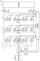
- FIG. 2 is a schematic configuration diagram when the power conversion device 1 is configured by the MMC conversion method.
- the power converter 1 is composed of an MMC converter including a plurality of submodules (corresponding to “SM” in FIG. 2) 7 connected in series with each other.
- the power converter 2 has a plurality of leg circuits 4u, which are connected in parallel to each other between the positive electrode DC terminal (that is, the high potential side DC terminal) Np and the negative electrode DC terminal (that is, the low potential side DC terminal) Nn.
- Includes 4v and 4w hereinafter, referred to as "leg circuit 4" when generically or arbitrarily indicated).
- the leg circuit 4 is provided in each of the plurality of phases constituting the alternating current.
- the leg circuit 4 is connected between the AC system 12 and the DC system 14, and performs power conversion between the two systems.
- the power converter 2 is provided with three leg circuits 4u, 4v, 4w corresponding to the U phase, the V phase, and the W phase, respectively.
- the AC input terminals Nu, Nv, Nw provided in the leg circuits 4u, 4v, 4w, respectively, are connected to the AC system 12 via the transformer 13.
- the connection between the AC input terminals Nv, Nw and the transformer 13 is not shown for ease of illustration.
- the high-potential side DC terminal Np and the low-potential side DC terminal Nn commonly connected to each leg circuit 4 are connected to the DC system 14.
- the leg circuit 4u includes an upper arm 5 from the high potential side DC terminal Np to the AC input terminal Nu, and a lower arm 6 from the low potential side DC terminal Nn to the AC input terminal Nu.
- the AC input terminal Nu which is the connection point between the upper arm 5 and the lower arm 6, is connected to the transformer 13. Since the leg circuits 4v and 4w have the same configuration, the leg circuits 4u will be described below as a representative.
- the upper arm 5 includes a plurality of cascade-connected submodules 7 and a reactor 8A.
- the plurality of submodules 7 and the reactor 8A are connected in series with each other.
- the lower arm 6 includes a plurality of cascaded submodules 7 and a reactor 8B.
- the plurality of submodules 7 and the reactor 8B are connected in series with each other.
- the power conversion device 1 includes an AC voltage detector 10, an AC current detector 16, and DC voltage detectors 11A and 11B as each detector for measuring the amount of electricity (for example, current, voltage, etc.) used for control. And arm current detectors 9A and 9B provided in each leg circuit 4. The signals detected by these detectors are input to the control device 3.
- the signal line of the signal input from each detector to the control device 3 and the signal line of the signal input / output between the control device 3 and each submodule 7 are one. Although the parts are described together, they are actually provided for each detector and each submodule 7.
- the signal lines between each submodule 7 and the control device 3 may be provided separately for transmission and reception.
- the signal line is composed of, for example, an optical fiber.
- the AC voltage detector 10 detects the U-phase AC voltage Vacu, the V-phase AC voltage Vacv, and the W-phase AC voltage Vacw of the AC system 12.
- the AC current detector 16 detects the U-phase AC current Iacu, the V-phase AC current Iacv, and the W-phase AC current Iacw of the AC system 12.
- the DC voltage detector 11A detects the DC voltage Vdcp of the high potential side DC terminal Np connected to the DC system 14.
- the DC voltage detector 11B detects the DC voltage Vdcn of the low potential side DC terminal Nn connected to the DC system 14. The difference between the DC voltage Vdcp and the DC voltage Vdcn is defined as the DC voltage Vdc.
- the arm current detectors 9A and 9B provided in the leg circuit 4u for the U phase detect the upper arm current Ipu flowing through the upper arm 5 and the lower arm current Inu flowing through the lower arm 6, respectively.
- the arm current detectors 9A and 9B provided in the V-phase leg circuit 4v detect the upper arm current Ipv and the lower arm current Inv, respectively.
- the arm current detectors 9A and 9B provided in the leg circuit 4w for the W phase detect the upper arm current Ipw and the lower arm current Inw, respectively.
- FIG. 3 is a circuit diagram showing an example of submodules constituting each leg circuit of FIG.
- the sub-module 7 shown in FIG. 3 has a circuit configuration called a half-bridge configuration.
- the sub-module 7 includes a series body formed by connecting two switching elements 31p and 31n in series, a power storage element 32, and a voltage detector 33. The series body and the power storage element 32 are connected in parallel.
- the voltage detector 33 detects the voltage across the power storage element 32.
- Both terminals of the switching element 31n are input / output terminals P1 and P2.
- the voltage across the power storage element 32 and the zero voltage are output by the switching operation of the switching elements 31p and 31n. For example, when the switching element 31p is turned on and the switching element 31n is turned off, the voltage across the power storage element 32 is output. A zero voltage is output when the switching element 31p is off and the switching element 31n is on.
- both terminals of the switching element 31n are input / output terminals P1 and P2, but both terminals of the switching element 31p may be input / output terminals P1 and P2, in which case the operation is reversed.
- the switching elements 31p and 31n are self-extinguishing semiconductor switching elements such as IGBT (Insulated Gate Bipolar Transistor), GCT (Gate Commutated Turn-off) psyllista, and MOSFET (Metal Oxide Semiconductor Field-Effect Transistor). (FWD: Freewheeling Diode) is connected in anti-parallel.
- a film capacitor or the like is mainly used for the power storage element 32.
- the configuration of the submodule 7 described above is an example, and submodules 7 having other configurations may be applied to the present embodiment.
- the sub-module 7 may be configured by using a full-bridge type conversion circuit.
- the control device 3 controls the operation of the power converter 2 based on the input current value and voltage value.
- the control device 3 typically includes an auxiliary transformer, an AD (Analog to Digital) converter, an arithmetic unit, and the like as a hardware configuration.
- the calculation unit includes a CPU (Central Processing Unit), a RAM (Random Access Memory), and a ROM (Read Only Memory).
- the AD conversion unit includes an analog filter, a sample hold circuit, a multiplexer, and the like.
- the control device 3 is composed of, for example, a digital protection control device.
- FIG. 4 is a diagram showing an example in which an air-core reactor is applied as the impedance circuit 41.
- the air-core reactor 43 as the impedance circuit 41 is connected between the neutral point 62 on the secondary side of the transformer 13 and the ground.
- the reactor has a high impedance in terms of alternating current, but has a low impedance (for example, ideally zero) in terms of direct current. Therefore, by grounding the neutral point 62 via the air-core reactor 43, the impedance becomes low in terms of direct current and effective grounding can be performed, and the impedance becomes high in terms of alternating current, and the accident current can be reduced. ..
- a method of superimposing a third harmonic on the output voltage may be adopted. This method is used to cancel the third harmonic component of the line voltage and improve the output voltage utilization rate by appropriately superimposing the third harmonic.
- the third harmonic is applied to the neutral point of the transformer 13 even in the normal time when no accident occurs, and the accompanying current flows to the ground.
- the air-core reactor 43 having a high AC impedance as the impedance circuit 41 the current flowing to the ground due to the third harmonic can be reduced. Therefore, the increase in loss due to the current flowing through the ground and the impact on the environment can be reduced.
- the third harmonic is distributed to the terminals on the AC side and the DC side due to the impedance balance to the ground on the AC side and the DC side of the power converter 2.
- the ratio of the third harmonic applied to the DC side (that is, the DC system 14 side) of the power converter 2 increases. To do. Therefore, in the DC transmission lines 14P and 14N, a waveform in which the third harmonic is superimposed on the DC voltage appears, and there are problems in terms of the insulation design of the DC transmission lines 14P and 14N, radio noise, induced current and the like.
- the third harmonic superimposed on the DC side can be reduced.
- the impedance Zg of the impedance circuit 41 (here, the air-core reactor 43) is set based on the following three conditions A1 to A3.
- the conditions A1 to A3 are not only the configuration in which the air-core reactor 43 is applied as the impedance circuit 41, but also the conditions that are commonly applied to various configurations of the impedance circuit 41 described below.
- the impedance Zg is set so as to satisfy the condition A2 that the current Ig flowing to the ground is set to the current threshold value Is or less by applying the third harmonic to the neutral point 62.
- the impedance Zg is set so as to satisfy the condition A3 that the ratio of the third harmonic applied to the DC side of the power converter 2 is X% of the whole.
- the impedance on the AC side of the power converter 2 is Zac and the impedance on the DC side is Zdc
- X 100 ⁇ ⁇ Zdc / (Zac + Zdc) ⁇ .
- Zac Zg + Zac0. Therefore, by appropriately setting the impedance Zg, the ratio of the third harmonic applied to the DC side of the power converter 2 can be adjusted to be X% of the whole.
- the impedance (more specifically, the inductance) of the air-core reactor 43 is set so as to satisfy the conditions A1 to A3. As a result, it is possible to reduce the current at the time of a ground fault, reduce the current due to the third harmonic in the normal state, and alleviate the vibration of the DC voltage due to the superposition of the third harmonic.
- the air-core reactor 43 has an advantage that there is no concern about a large current due to saturation because there is no risk of saturation even if a DC voltage is superimposed on the neutral point 62 or the AC line 64 at the time of a ground fault.
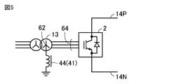
- FIG. 5 is a diagram showing an example in which an iron core reactor is applied as the impedance circuit 41.
- the iron core reactor 44 as the impedance circuit 41 is connected between the neutral point 62 on the secondary side of the transformer 13 and the ground.
- the effect of reducing the accident current at the time of a ground fault on the AC side or the DC side of the power converter 2 the effect of reducing the current flowing to the ground at normal times, and the third harmonic component superimposed on the DC transmission lines 14P and 14N.
- the reduction effect increases as the impedance of the impedance circuit 41 increases.
- the iron core reactor 44 can easily increase the inductance, that is, the impedance value with respect to the alternating current without increasing the scale. On the other hand, even if the inductance is increased, the impedance is not increased in terms of direct current, so that the effect of fixing the direct current potential to ground is not impaired.
- FIG. 6 is a diagram showing an example in which an iron core reactor with a gap is applied as the impedance circuit 41.
- the gapped iron core reactor 45 as the impedance circuit 41 is connected between the neutral point 62 on the secondary side of the transformer 13 and the ground.
- the iron core reactor 45 with a gap is less likely to saturate than the iron core reactor 44 in FIG. Therefore, it is possible to prevent the accident current from becoming excessive due to saturation when the DC voltage is superimposed on the neutral point 62 or the AC line 64 at the time of a ground fault of the DC system 14 or the AC line 64.
- the iron core reactor 45 with a gap has an iron core, the inductance can be easily increased as compared with the air core reactor 43 of FIG. Therefore, when it is necessary to increase the inductance in order to satisfy the above conditions A1 to A3, a configuration in which the iron core reactor 45 with a gap is applied is more advantageous than applying the air core reactor 43 as the impedance circuit 41.
- FIG. 7 is a diagram showing an example in which a series circuit of an iron core reactor and a resistor is applied as the impedance circuit 41.
- the impedance circuit 41 is composed of a series circuit in which the iron core reactor 44 and the resistor 46 are connected in series.
- the impedance circuit 41 may be composed of a series circuit in which the iron core reactor 45 with a gap and the resistor 46 are connected in series.
- the resistance value of the resistor 46 is too large, the impedance circuit 41 becomes high impedance in terms of direct current, and the effect of fixing the DC potential to ground of the power converter 2 is reduced. Therefore, the resistance value of the resistor 46 needs to be set to such an extent that the effect of fixing the DC potential to the ground of the power converter 2 is ensured.
- FIG. 8 is a diagram showing an example in which a voltage transformer is applied as the impedance circuit 41.
- the voltage transformer 47 as the impedance circuit 41 is connected between the neutral point 62 on the secondary side of the transformer 13 and the ground. Specifically, the primary winding of the voltage transformer 47 is connected between the neutral point 62 and the ground.
- the voltage transformer 47 functions as an inductor, the same effect as that of the iron core reactor 44 described above can be obtained.
- the impedance of the voltage transformer 47 is set so as to satisfy the above conditions A1 to A3.
- FIG. 9 is a diagram showing an example in which a series circuit of a voltage transformer and a resistor is applied as the impedance circuit 41.
- the impedance circuit 41 is composed of a series circuit in which the voltage transformer 47 and the resistor 46 are connected in series.
- the primary current withstand capacity of the voltage transformer 47 is small. Therefore, when the voltage transformer 47 is saturated, the voltage transformer 47 may burn out unless the current flowing at that time is reduced.
- the DC voltage is superimposed on the neutral point 62 or the AC line 64 in the event of a ground fault in the DC system 14 or the AC line 64.
- the DC voltage applied to the instrument transformer 47 can be reduced. Therefore, the voltage transformer 47 is less likely to be saturated. Further, even if the voltage transformer 47 is saturated, the accident current can be reduced by the resistance 46.
- the resistance value of the resistor 46 needs to be set to such an extent that the effect of fixing the DC potential to the ground of the power converter 2 is ensured.
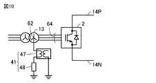
- FIG. 10 is a diagram showing an example in which a series circuit of a voltage transformer and a fuse is applied as the impedance circuit 41.
- the impedance circuit 41 is composed of a series circuit in which the voltage transformer 47 and the fuse 48 are connected in series.
- the fuse 48 is connected in series with the voltage transformer 47, the DC voltage is superimposed on the neutral point 62 or the AC line 64 in the event of a ground fault in the DC system 14 or the AC line 64. Even if the voltage transformer 47 is saturated at that time, the fault current can be cut off by the fuse 48 before the fault current becomes excessive. As a result, it is possible to prevent the voltage transformer 47 from burning out.
- the fuse 48 is configured to be blown below the current withstand capacity of the voltage transformer 47.
- the voltage transformer 47 in the normal state, is used to obtain a low impedance in terms of direct current and effectively ground the ground, and a high impedance in terms of alternating current to reduce the accident current. To do. Further, in the event of an accident, the fuse 48 is blown before the accident current becomes excessive, so that the voltage transformer 47 can be protected more accurately.
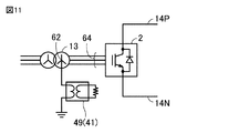
- FIG. 11 is a diagram showing an example in which a grounding transformer is applied as the impedance circuit 41.
- the grounding transformer 49 as the impedance circuit 41 is connected between the neutral point 62 on the secondary side of the transformer 13 and the ground.
- the primary winding of the grounding transformer 49 is connected between the neutral point 62 and the ground. Since the grounding transformer 49 functions as an inductor, the same effect as that of the iron core reactor 44 described above can be obtained.
- the grounding transformer 49 when the neutral point 62 is grounded via the grounding transformer 49, the impedance becomes low in terms of direct current and effective grounding can be performed, and the impedance becomes high in terms of alternating current, resulting in an accident current. Can be reduced. Further, in general, the grounding transformer 49 has a larger current withstand capacity than the instrument transformer 47. Therefore, even if the grounding transformer 49 is saturated at the time of a ground fault in the DC system 14 or the AC line 64, the grounding transformer 49 is less likely to burn out than the voltage transformer 47. Has.
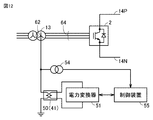
- FIG. 12 is a diagram showing an example in which a power converter is connected to a transformer for a power converter as an impedance circuit 41.
- the power converter transformer 50 as the impedance circuit 41 is connected between the neutral point 62 on the secondary side of the transformer 13 and the ground.
- the primary winding of the power converter transformer 50 is connected between the neutral point 62 and the ground. Since the transformer 50 for the power converter functions as an inductor, the same effect as that of the iron core reactor 44 described above can be obtained.
- the transformer 50 for a power converter is a single-phase transformer for power conversion, the primary winding thereof is connected between the neutral point 62 and the ground, and the secondary winding is connected to the power converter 51. ..
- the power converter 51 may be any self-excited or separately-excited power converter as long as it has a function of controlling voltage.
- control device 55 controls the operation of the power converter 51.
- control device 55 has the same hardware configuration as the control device 3, and is composed of, for example, a digital protection control device.
- the voltage detector 54 detects the voltage V Hood, which is the voltage to ground between the neutral point 62 and the ground.
- the control device 55 receives the input of the voltage V Mother detected by the voltage detector 54 and constantly monitors the voltage Vo.
- the control device 55 makes the power converter 51 stand by without operating.
- the control device 55 detects an increase in the voltage V réelle and controls the power converter 51 so as to output the opposite voltage of the voltage V réelle.
- the difference voltage between the voltage V réelle and the primary side voltage V1 of the power converter transformer 50 is the threshold voltage Vth.
- the secondary side voltage V2 of the power converter transformer 50 is controlled so as to be less than.
- the difference voltage is the difference between the amplitude value of the voltage V Cincinnati and the amplitude value of the primary side voltage V1, or the difference between the effective value of the voltage V Cincinnati and the effective value of the primary side voltage V1.
- the accident current flowing through the transformer 50 for the power converter can be reduced.
- the power converter transformer 50 in the normal state, has a low impedance in terms of direct current and can be effectively grounded, and has a high impedance in terms of alternating current to reduce the accident current. Can be reduced. Further, in the event of an accident, the secondary side voltage V2 of the power converter transformer 50 is controlled so as to output the opposite voltage (that is, the primary side voltage V1) with respect to the ground voltage of the neutral point 62, so that the accident current Can be reduced.
- FIG. 13 is a diagram showing an example in which a filter circuit is applied as the impedance circuit 41.
- the filter circuit 56 as the impedance circuit 41 is a parallel circuit in which the reactor 58 and the capacitor 57 are connected in parallel.
- the reactor 58 may be any of the above-mentioned air core reactor 43, iron core reactor 44, and iron core reactor 45 with a gap.
- the third harmonic is applied to the neutral point 62 of the transformer 13 in both normal times and in the event of a ground fault.
- the fundamental wave is also applied to the neutral point 62. Therefore, in order to reduce the current flowing through the ground, it is preferable that the impedance circuit 41 has a high impedance with respect to the voltage of at least each frequency of the fundamental wave and the third harmonic.
- a filter circuit 56 having a high impedance with respect to the fundamental wave component and the third harmonic component of the output voltage of the power converter 2 is connected between the neutral point 62 and the ground.
- the filter circuit 56 is configured to attenuate the fundamental wave component and the third harmonic component of the output voltage of the power converter 2.
- the filter circuit 56 may be a low-pass filter that attenuates a voltage corresponding to a frequency higher than the frequency corresponding to the fundamental wave component (that is, the fundamental frequency).
- the filter circuit 56 When the reactor alone realizes high impedance for the fundamental wave component and the third harmonic component, the scale becomes large, but according to the filter circuit 56, the scale can be reduced. Further, according to the filter circuit 56, by adjusting the inductance of the reactor 58 and the capacitance of the capacitor 57, it is possible to realize a high impedance with respect to a specified order. Further, since the filter circuit 56 is composed of a parallel circuit of the reactor 58 and the capacitor 57, the direct current flows through the reactor 58. Therefore, the impedance does not increase in terms of direct current, and the direct current potential of the power converter 2 to ground can be fixed.
- the ground current at the time of normal operation and at the time of a ground fault can be reduced while reducing the scale of the impedance circuit 41.
- FIGS. 4 to 13 a configuration example of the impedance circuit 41 has been described. Here, the method of setting the inductance of the impedance circuit 41 will be described.
- the control device 3 controls the power converter 2 at a predetermined control frequency Fs. Therefore, if the control frequency Fs for controlling the power converter 2 exists within a certain range centered on the resonance frequency, resonance may occur and the operation of the power converter 2 may become unstable. is there.
- the inductance Ls of the impedance circuit 41 is set so that the above resonance does not occur. Specifically, the floating capacitance C1 between the power converter 2 and the ground and the floating capacitance C2 between the DC system 14 and the ground are estimated in advance. Next, the resonance frequency f1 defined by the floating capacitance C1 and the inductance Ls, and the resonance frequency f2 defined by the floating capacitance C2 and the inductance Ls are calculated.
- the inductance Ls of the impedance circuit 41 is set so as to satisfy the above condition Y2.
- the configuration may consider the floating capacitance existing between the peripheral device (for example, the cooling device) of the power converter 2 and the ground.
- the resonance frequency f3 defined by the floating capacitance C3 between the peripheral device and the ground and the inductance Ls is calculated.
- the inductance Ls may be set so that the difference between the resonance frequency f3 and the control frequency Fs satisfies the condition Y3 with the threshold value Fth or more.
- the inductance Ls may be set in consideration of only one of the conditions Y1 to Y3 according to the influence on the operation of the power converter 2. For example, the inductance Ls may be set so as to satisfy only the condition Y1, or the inductance Ls may be set so as to satisfy only the condition Y2.
- the power converter 2 can be operated stably. Further, by designing the impedance circuit 41 that satisfies the above-mentioned conditions A1 to A3 and conditions Y1 to Y3, the current in the event of a ground fault can be reduced, the current due to the third harmonic in the normal state can be reduced, and the DC voltage. It is possible to alleviate the vibration and prevent the occurrence of resonance.
- Embodiment 2 In the first embodiment, as shown in FIG. 1, a configuration in which the impedance circuit 41 is connected to the neutral point 62 of the transformer 13 has been described. In the second embodiment, a configuration in which an impedance circuit is connected to the neutral point 62 of the transformer 13 and the neutral point 62A of the transformer 13A will be described.
- FIG. 14 is a diagram showing a schematic configuration of the power conversion system 100A according to the second embodiment.
- the power conversion system 100A corresponds to a configuration in which switches 61 and 61A and an impedance circuit 41A connected to the neutral point 62A are added to the power conversion system 100 of FIG.
- the impedance circuit 41A has a configuration similar to that of the impedance circuit 41.
- the impedance circuit 41A is connected between the neutral point 62A and the ground.
- the switch 61 is connected in series with the impedance circuit 41. Specifically, the switch 61 is connected between the impedance circuit 41 and the ground. However, the switch 61 may be connected between the neutral point 62 and the impedance circuit 41.
- the switch 61A is connected in series with the impedance circuit 41A. Specifically, the switch 61A is connected between the impedance circuit 41A and the ground. However, the switch 61A may be connected between the neutral point 62A and the impedance circuit 41A.
- BTB or HVDC is realized by connecting two or more power converters 2 by a DC transmission line.
- either the neutral point 62 of the transformer 13 or the neutral point 62A of the transformer 13A is passed through an impedance circuit. You just have to ground it. On the contrary, when the neutral point 62 and the neutral point 62A are grounded through the impedance circuit, a loop current flows through the neutral point 62, the ground, and the neutral point 62A, which increases the loss and has an environmental impact. It is not preferable.
- BTB or HVDC even if either power converter 2 or 2A becomes inoperable at the time of an accident or maintenance, it may be required to operate only with a sound power converter. is there.
- the switch (not shown) provided in the DC transmission line (that is, the DC system 14) is opened, and the inoperable power converter is separated from the sound power converter to be invalid. It is assumed that only power is output to the grid. In such a case, in order to fix the DC voltage to ground of the sound power converter, the neutral point of the transformer connected to the sound power converter needs to be grounded via the impedance circuit.
- the neutral point of the transformer connected to either one of the power converters 2 and 2A is grounded via the impedance circuit, and the other neutral point is not grounded. Then, when the power converter connected to the transformer having the grounded neutral point becomes inoperable, the neutral point of the transformer connected to the other power converter is grounded via the impedance circuit. It is preferable that it is configured so that it can be used.
- the neutral point 62 is grounded via the impedance circuit 41 and the switch 61, and the neutral point 62A is grounded via the impedance circuit 41A and the switch 61A.
- the switches 61 and 61A In the normal state, by controlling the switches 61 and 61A, only one of the neutral points 62 and 62A is grounded via the impedance circuit 41 or 41A. That is, one of the switch 61 and the switch 61A is closed, and the other is open.
- the DC potential of the power converters 2 and 2A can be fixed, and the loop current does not flow through the neutral points 62 and 62A and the ground at normal times.
- a switch (not shown) provided in the DC system 14 is opened. This disconnects the power converter 2 from the system. Further, by opening the switch 61 and closing the switch 61A, the neutral point 62A is grounded via the impedance circuit 41A. As a result, the DC potential of the sound power converter 2A to the ground can be fixed.
- the opening and closing of the switch 61 is controlled by the control device 3, and the opening and closing of the switch 61A is controlled by the control device 3A.
- the opening and closing of the switch provided in the DC system 14 is controlled by the control device 3 or 3A.
- the control device 3 stops the operation of the power converter 2 when an accident occurs on the AC side or the DC side of the power converter 2 (or when the maintenance time of the power converter 2 comes). Further, the control device 3 opens an AC circuit breaker (not shown) provided between the AC system 12 and the transformer 13, and opens a switch provided in the DC system 14 to open the power converter. Separate 2 from the system. Further, the control device 3 opens the switch 61.
- the control device 3 executes a control calculation based on the amount of electricity acquired from each detector (for example, AC current detector 16, AC voltage detector 10, DC voltage detector 11A, 11B), and sets the calculated value. If it exceeds the value, it may be determined that an accident has occurred, or a notification that an accident has occurred may be received from an external device. Further, the control device 3 may determine the arrival of the maintenance time based on the information stored in advance in the internal memory, or may receive a notification indicating the arrival of the maintenance time from the external device.
- each detector for example, AC current detector 16, AC voltage detector 10, DC voltage detector 11A, 11B
- control device 3A When the control device 3A receives the notification from the control device 3 that the operation of the power converter 2 is stopped, the control device 3A closes the switch 61A. As a result, the neutral point 62A is grounded via the impedance circuit 41.
- Embodiment 3 In the first embodiment described above, the configuration in which the impedance circuit 41 is connected between the neutral point 62 and the ground has been described. In the third embodiment, a configuration in which an impedance circuit is connected between the AC line 64 and the ground will be described.
- FIG. 15 is a diagram showing a schematic configuration of the power conversion system 100B according to the third embodiment.
- the power conversion system 100B does not connect the impedance circuit 41 to the neutral point 62 as in the power conversion system 100 of FIG. 1, but connects the impedance circuit 41 to the AC line 64. It differs from the power conversion system 100 in that it is configured. Other configurations of the power conversion system 100B are the same as those of the power conversion system 100.
- the impedance circuit 41 is connected between each phase (for example, U phase, V phase, W phase) of the AC line 64 and the ground.
- the DC potential to ground of the power converter 2 can be fixed in the same manner as in the configuration in which the neutral point 62 is grounded via the impedance circuit 41 as in the power conversion system 100 shown in FIG.
- a transformer having a connection without providing a neutral point on the secondary side is used as the transformer 13.
- a transformer having a connection without providing a neutral point on the secondary side is used as the transformer 13.
- a Y- ⁇ connection three-phase transformer can be adopted as the transformer 13.
- a ⁇ connection is applied to any winding of the transformer 13 in order to prevent the third harmonic from flowing out to the AC system 12.
- the primary winding of the transformer 13 is often Y-connected.
- the secondary winding of the transformer 13 is Y-connected and the tertiary winding of the ⁇ connection is newly connected in order to provide a neutral point. It is preferable to provide in. Therefore, it is necessary to adopt a YY- ⁇ connection three-phase transformer as the transformer 13.
- the number of impedance circuits 41 increases as compared with the power conversion system 100, but since a Y- ⁇ connection three-phase transformer can be adopted as the transformer 13, the cost of the transformer 13 is reduced. Can be reduced.
- each impedance circuit 41 shown in FIG. 15 can adopt the same configuration as the impedance circuit 41 shown in FIGS. 4 to 13.
- the voltage detector 54 for detecting the AC voltage of each phase and the voltage of each phase are controlled.
- a power converter 51 is provided for this purpose.
- the power converter 51 corresponding to each phase has a difference voltage between the AC voltage between the AC line 64 and the ground and the primary side voltage V1 of the transformer 50 for the power converter.
- the secondary side voltage V2 is controlled so as to be less than the threshold voltage Vth.
- the configuration may be a combination of the second embodiment and the third embodiment.
- the impedance circuit 41A is connected between the AC line 64A and the ground. More specifically, the impedance circuit 41 and the switch 61 are connected in series to each phase of the AC line 64, and the impedance circuit 41A and the switch 61A are connected in series to each phase of the AC line 64A. Then, the opening and closing of the switches 61 and 61A is controlled so that each phase of the AC line 64 or each phase of the AC line 64A is grounded via the impedance circuit 41. For example, when each switch 61 is closed and each phase of the AC line 64 is grounded via the impedance circuit 41, each switch 61A is open and each phase of the AC line 64A is not grounded. ..
- Embodiment 4 In the above-described embodiment, the configuration in which the AC side of the power converter 2 (for example, each phase of the neutral point 62 and the AC line 64) is grounded via the impedance circuit 41 has been described. In the fourth embodiment, a configuration in which the DC side of the power converter 2 is grounded via an impedance circuit will be described.
- FIG. 16 is a diagram showing a schematic configuration of a power conversion system 100C according to the fourth embodiment.
- the power conversion system 100C is configured to connect the impedance circuit to the DC system 14 instead of connecting the impedance circuit 41 to the neutral point 62 as in the power conversion system 100 of FIG. It differs from the power conversion system 100 in that it is performed.
- Other configurations of the power conversion system 100C are the same as those of the power conversion system 100.
- the impedance circuit 71 is connected to the DC transmission line 14P on the positive electrode side, and the impedance circuit 72 is connected to the DC transmission line 14N on the negative electrode side.
- the line connecting the impedance circuit 71 and the impedance circuit 72 is grounded.
- the impedance circuits 71 and 72 need to have a high impedance in terms of direct current in order to reduce the current flowing during normal times and accidents. Therefore, the impedance circuits 71 and 72 are composed of at least one of a resistor and a capacitor. Therefore, the impedance circuits 71 and 72 are different from the above-mentioned impedance circuit 41, which has a low impedance in terms of direct current.
- the configuration in which the line connecting the impedance circuit 71 and the impedance circuit 72 is grounded has been described, but the configuration is not limited to this configuration.
- the impedance circuits 71 and 72 may be directly grounded without connecting the impedance circuit 71 and the impedance circuit 72. Therefore, the DC transmission line 14P on the positive electrode side may be grounded via the impedance circuit 71, and the DC transmission line 14N on the negative electrode side may be grounded via the impedance circuit 72.
- the self-excited power converter 2 flows while fixing the DC potential to the ground during normal times and during an accident.
- the current can be reduced.
- FIG. 17 is a diagram showing a schematic configuration of a power conversion system 100D according to the fifth embodiment.
- the impedance to ground on the DC side of the power converter 2 is configured to be balanced between the positive electrode and the negative electrode.
- a cooling device or the like is attached to the power converter 2, and there is a ground impedance such as a floating capacitance and an insulation resistance between the auxiliary device and the ground.
- the DC system 14 has a capacitance to ground according to the line length.
- the ground impedance 81 is the ground impedance existing between the DC terminal and the DC transmission line 14P on the positive electrode side of the power converter 2 and the ground.
- the ground impedance 82 is the ground impedance existing between the DC terminal and the DC transmission line 14N on the negative electrode side of the power converter 2 and the ground.
- the ground DC potential of the power converter 2 can be fixed. Therefore, a device or the like having the ground impedance is designed so that the ground impedance 81 and the ground impedance 82 are in equilibrium. If the ground impedance 81 and the ground impedance 82 are not balanced due to the configuration, an impedance circuit 83 is added to the DC transmission line 14P or 14N so that the ground impedance is balanced between the positive electrode and the negative electrode. In the example of FIG. 17, the impedance circuit 83 is connected to the DC transmission line 14N. As a result, the DC potential of the power converter 2 can be fixed.
- the ground DC potential of the power converter 2 can be fixed by designing the power converter 2 so that the impedance to the ground on the positive electrode side and the negative electrode side is balanced.
- FIG. 18 is a diagram showing an example in which a power converter is applied as an impedance circuit.
- the power converter 91 as the impedance circuit 41 is connected between the neutral point 62 on the secondary side of the transformer 13 and the ground.
- the control device 93 controls the operation of the power converter 91.
- the control device 93 has the same hardware configuration as the control device 3, and is composed of, for example, a digital protection control device.
- the voltage detector 54 detects the voltage V Hood, which is the voltage to ground between the neutral point 62 and the ground.
- the control device 93 receives the input of the voltage V Mother detected by the voltage detector 54 and constantly monitors the voltage Vo.
- the power converter 91 controls the output voltage so as to be equivalent to the inductor when viewed from the neutral point 62 according to the instruction of the control device 93.
- the control device 93 determines whether an AC voltage is applied to the neutral point 62, a DC voltage is applied to the neutral point 62, or an AC voltage and a DC voltage are applied to the neutral point 62 based on the voltage V réelle. Determine if both voltages are applied.
- the control device 93 satisfies the condition B1 that the polarity of the voltage applied to the neutral point 62 changes periodically and the voltage is positive or negative and symmetrical, the neutral point. It is determined that an AC voltage is applied to 62.
- control device 93 when the control device 93 satisfies the condition B2 that the polarity of the voltage applied to the neutral point 62 is constant and the amplitude of the voltage does not change, the DC voltage is applied to the neutral point 62. Judge that it is done. Further, the control device 93 states that when the voltage applied to the neutral point 62 does not satisfy both the condition B1 and the condition B2, both the AC voltage and the DC voltage are applied to the neutral point 62. judge.
- the control device 93 determines that the AC voltage is applied to the neutral point 62, the control device 93 outputs the opposite voltage of the voltage V réelle from the power converter 91. Specifically, according to the instruction of the control device 93, in the power converter 91, the difference voltage between the voltage V réelle and the output voltage Vs of the power converter 91 (that is, the opposite voltage of the voltage Vschreib) becomes less than the threshold voltage Vth.
- the output voltage Vs is controlled so as to.
- the difference voltage is the difference between the amplitude value of the voltage V Cincinnati and the amplitude value of the output voltage Vs, or the difference between the effective value of the voltage V desires and the effective value of the output voltage Vs. As a result, the alternating current flowing to the ground can be reduced.
- the control device 93 determines that the DC voltage is applied to the neutral point 62 based on the voltage V réelle, the control device 93 outputs a zero voltage from the power converter 91. Specifically, the power converter 91 controls the output voltage Vs to zero voltage according to the instruction of the control device 93. This causes current to flow to ground.
- the power converter 91 when the control device 93 determines that the AC voltage and the DC voltage are applied to the neutral point 62 based on the voltage V réelle, the power converter 91 outputs an opposite voltage to only the AC component of the voltage V réelle. .. Specifically, the control device 93 generates an AC voltage V Azureac obtained by extracting only an AC component from the voltage V réelle. According to the instruction of the control device 93, the power converter 91 controls the output voltage Vs so that the difference voltage between the AC voltage V réelleac and the output voltage Vs of the power converter 91 is less than the threshold voltage Vth. In this case, the output voltage Vs corresponds to the opposite voltage of the AC component of the voltage V plin (that is, the AC voltage V Fujiac). As a result, the DC current component can flow to the ground while reducing the AC current component flowing to the ground.
- the power converter 91 can be regarded as an inductor equivalently, and the same effect as the grounding by the iron core reactor 44 described above can be obtained. ..
- the control device 93 outputs the opposite voltage of the voltage V réelle from the power converter 91. Specifically, according to the instruction of the control device 93, the power converter 91 controls the output voltage Vs so that the difference voltage between the voltage V réelle and the output voltage Vs is less than the threshold voltage Vth. As a result, the accident current flowing to the ground can be reduced.
- the power converter 91 has a low impedance in terms of direct current and can be effectively grounded, and has a high impedance in terms of alternating current. Can be reduced. Further, in the event of an accident, the power converter 91 is controlled so as to output the opposite voltage (that is, the output voltage Vs) with respect to the ground voltage of the neutral point 62, so that the accident current can be reduced.
- the opposite voltage that is, the output voltage Vs
- the voltage detector 54 for detecting the AC voltage of each phase and the voltage of each phase are controlled.
- a power converter 91 is provided for this purpose. In this case, according to the instruction of the control device 93, the power converter 91 corresponding to each phase executes the control operation as described above.
Landscapes
- Engineering & Computer Science (AREA)
- Power Engineering (AREA)
- Inverter Devices (AREA)
- Protection Of Static Devices (AREA)
- Rectifiers (AREA)
Abstract
La présente invention concerne un système de conversion de puissance (100) qui est pourvu : d'un convertisseur de puissance auto-excité (2) qui convertit la puissance entre une première ligne en courant alternatif (CA) (12) et une ligne en courant continu (CC) (14) ; un premier transformateur (13) qui est connecté, sur un côté primaire, à la première ligne en CA et connecté, sur un côté secondaire, au convertisseur de puissance auto-excité ; et un premier circuit d'impédance (41) qui est connecté entre une masse et un point neutre (62) du côté secondaire du premier transformateur ou entre une masse et une ligne en CA (64) connectant le côté secondaire du premier transformateur et le convertisseur de puissance auto-excité. Le premier circuit d'impédance comprend soit un réacteur (43 44, 45) soit un autre transformateur (47, 49, 50).
Priority Applications (4)
| Application Number | Priority Date | Filing Date | Title |
|---|---|---|---|
| PCT/JP2019/031382 WO2021024455A1 (fr) | 2019-08-08 | 2019-08-08 | Système de conversion de puissance |
| US17/628,994 US11722069B2 (en) | 2019-08-08 | 2019-08-08 | Power conversion system |
| JP2020511823A JP6793876B1 (ja) | 2019-08-08 | 2019-08-08 | 電力変換システム |
| EP19940576.2A EP4012867A4 (fr) | 2019-08-08 | 2019-08-08 | Système de conversion de puissance |
Applications Claiming Priority (1)
| Application Number | Priority Date | Filing Date | Title |
|---|---|---|---|
| PCT/JP2019/031382 WO2021024455A1 (fr) | 2019-08-08 | 2019-08-08 | Système de conversion de puissance |
Publications (1)
| Publication Number | Publication Date |
|---|---|
| WO2021024455A1 true WO2021024455A1 (fr) | 2021-02-11 |
Family
ID=73544721
Family Applications (1)
| Application Number | Title | Priority Date | Filing Date |
|---|---|---|---|
| PCT/JP2019/031382 Ceased WO2021024455A1 (fr) | 2019-08-08 | 2019-08-08 | Système de conversion de puissance |
Country Status (4)
| Country | Link |
|---|---|
| US (1) | US11722069B2 (fr) |
| EP (1) | EP4012867A4 (fr) |
| JP (1) | JP6793876B1 (fr) |
| WO (1) | WO2021024455A1 (fr) |
Cited By (2)
| Publication number | Priority date | Publication date | Assignee | Title |
|---|---|---|---|---|
| JP7387062B1 (ja) * | 2022-09-27 | 2023-11-27 | 三菱電機株式会社 | 電力変換システム |
| JP7538457B1 (ja) | 2024-01-17 | 2024-08-22 | 日新電機株式会社 | 保護システム |
Families Citing this family (1)
| Publication number | Priority date | Publication date | Assignee | Title |
|---|---|---|---|---|
| WO2022044091A1 (fr) * | 2020-08-24 | 2022-03-03 | 日立三菱水力株式会社 | Convertisseur de puissance multiniveau modulaire et système de conversion de puissance multiniveau modulaire |
Citations (7)
| Publication number | Priority date | Publication date | Assignee | Title |
|---|---|---|---|---|
| JP2003033039A (ja) * | 2001-07-18 | 2003-01-31 | Hitachi Ltd | 多重接続した自励式変換器の制御装置 |
| JP2011147244A (ja) * | 2010-01-13 | 2011-07-28 | Kansai Electric Power Co Inc:The | 地絡電流抑制システム |
| JP2011196729A (ja) * | 2010-03-18 | 2011-10-06 | Kansai Electric Power Co Inc:The | 直流回路の漏電検出装置および方法 |
| JP2012130107A (ja) * | 2010-12-13 | 2012-07-05 | Chugoku Electric Power Co Inc:The | 地絡保護継電システムおよび地絡保護方法 |
| US20130016541A1 (en) * | 2010-03-04 | 2013-01-17 | Abb Research Ltd | Ac/dc converter station and a method of operating an ac/dc converter station |
| JP2015122908A (ja) * | 2013-12-24 | 2015-07-02 | 株式会社東芝 | 車両用制御装置 |
| JP2015130746A (ja) | 2014-01-07 | 2015-07-16 | 株式会社日立製作所 | 電力変換装置およびその制御方法 |
Family Cites Families (12)
| Publication number | Priority date | Publication date | Assignee | Title |
|---|---|---|---|---|
| JPH0767256A (ja) | 1993-08-25 | 1995-03-10 | Toshiba Corp | 他励式交直変換器の制御装置 |
| WO2011150962A1 (fr) | 2010-06-01 | 2011-12-08 | Abb Technology Ag | Agencement d'interfaçage entre des systèmes alternatif et continu, comportant un filtre au point neutre du transformateur |
| US8767422B2 (en) * | 2010-06-01 | 2014-07-01 | Abb Technology Ag | Interface arrangement between AC and DC systems using grounding switch |
| RU2524347C2 (ru) | 2012-05-15 | 2014-07-27 | Георгий Маркович Мустафа | Устройство компенсации тока замыкания на землю в трехфазных электрических сетях (варианты) |
| SE537081C2 (sv) * | 2012-08-03 | 2014-12-30 | Swedish Neutral Ab | En anordning innefattande en reglerbar jordningstransformator |
| CN103296671B (zh) * | 2013-04-09 | 2016-08-10 | 国家电网公司 | 用于柔性直流输电系统交流侧过电压保护装置及保护方法 |
| CN103986176B (zh) * | 2014-04-01 | 2016-09-21 | 南方电网科学研究院有限责任公司 | 一种将换流站带电接入多端柔性直流输电系统的方法 |
| CN105322528B (zh) | 2014-06-30 | 2019-01-11 | 中国石油大学(华东) | 小电流接地故障有源消弧时注入电流两点计算方法 |
| CN104155582B (zh) | 2014-08-29 | 2016-10-19 | 上海交通大学 | 基于全波形信息的配网线路故障区段定位方法 |
| CN104767191B (zh) * | 2015-04-09 | 2019-04-05 | 国家电网公司 | 一种换流器接地系统 |
| CN105119251B (zh) * | 2015-07-23 | 2018-04-13 | 华南理工大学 | 一种适用柔性直流配电系统接地电阻方案的确定方法 |
| EP3648331A4 (fr) * | 2017-06-27 | 2020-07-08 | Mitsubishi Electric Corporation | Dispositif de conversion de puissance |
-
2019
- 2019-08-08 WO PCT/JP2019/031382 patent/WO2021024455A1/fr not_active Ceased
- 2019-08-08 US US17/628,994 patent/US11722069B2/en active Active
- 2019-08-08 EP EP19940576.2A patent/EP4012867A4/fr active Pending
- 2019-08-08 JP JP2020511823A patent/JP6793876B1/ja active Active
Patent Citations (7)
| Publication number | Priority date | Publication date | Assignee | Title |
|---|---|---|---|---|
| JP2003033039A (ja) * | 2001-07-18 | 2003-01-31 | Hitachi Ltd | 多重接続した自励式変換器の制御装置 |
| JP2011147244A (ja) * | 2010-01-13 | 2011-07-28 | Kansai Electric Power Co Inc:The | 地絡電流抑制システム |
| US20130016541A1 (en) * | 2010-03-04 | 2013-01-17 | Abb Research Ltd | Ac/dc converter station and a method of operating an ac/dc converter station |
| JP2011196729A (ja) * | 2010-03-18 | 2011-10-06 | Kansai Electric Power Co Inc:The | 直流回路の漏電検出装置および方法 |
| JP2012130107A (ja) * | 2010-12-13 | 2012-07-05 | Chugoku Electric Power Co Inc:The | 地絡保護継電システムおよび地絡保護方法 |
| JP2015122908A (ja) * | 2013-12-24 | 2015-07-02 | 株式会社東芝 | 車両用制御装置 |
| JP2015130746A (ja) | 2014-01-07 | 2015-07-16 | 株式会社日立製作所 | 電力変換装置およびその制御方法 |
Non-Patent Citations (1)
| Title |
|---|
| See also references of EP4012867A4 |
Cited By (4)
| Publication number | Priority date | Publication date | Assignee | Title |
|---|---|---|---|---|
| JP7387062B1 (ja) * | 2022-09-27 | 2023-11-27 | 三菱電機株式会社 | 電力変換システム |
| WO2024069750A1 (fr) | 2022-09-27 | 2024-04-04 | 三菱電機株式会社 | Système de conversion de puissance électrique |
| JP7538457B1 (ja) | 2024-01-17 | 2024-08-22 | 日新電機株式会社 | 保護システム |
| JP2025111153A (ja) * | 2024-01-17 | 2025-07-30 | 日新電機株式会社 | 保護システム |
Also Published As
| Publication number | Publication date |
|---|---|
| JP6793876B1 (ja) | 2020-12-02 |
| US20220263424A1 (en) | 2022-08-18 |
| EP4012867A4 (fr) | 2022-08-03 |
| EP4012867A1 (fr) | 2022-06-15 |
| JPWO2021024455A1 (ja) | 2021-09-13 |
| US11722069B2 (en) | 2023-08-08 |
Similar Documents
| Publication | Publication Date | Title |
|---|---|---|
| CA2622057C (fr) | Dispositif de transmission d'energie electrique | |
| US9780556B2 (en) | Voltage sourced converter with semiconductor modules handling a DC current fault | |
| JP6833151B1 (ja) | 電力変換システム | |
| JP4812829B2 (ja) | 12パルス高圧直流送電 | |
| EP2471164B1 (fr) | Cellule de convertisseur avec autotransformateur comme derivation, convertisseur de source de tension avec telles cellules et méthode pour l'opération | |
| US20170338654A1 (en) | Modular multi-level converter with thyristor valves | |
| JP6793876B1 (ja) | 電力変換システム | |
| US11909305B2 (en) | AC-to-DC power converter which removed a common mode component form the output current | |
| GB2397445A (en) | Power transmission circuits | |
| US12009759B2 (en) | Power conversion system | |
| CN106797124B (zh) | Ac故障处理布置 | |
| EP4071996A1 (fr) | Dispositif de conversion de puissance | |
| EP4597781A1 (fr) | Système de conversion de puissance électrique | |
| Cui et al. | Enhanced dual-active bridge converter with inherent bipolar operation capability for LVDC distribution systems | |
| EP3416256A1 (fr) | Système de protection et de filtrage harmonique de convertisseur de courant continu haute tension | |
| JP7043607B2 (ja) | 電力変換装置 | |
| US12294291B2 (en) | Power conversion system | |
| US20240332922A1 (en) | Current damper for voltage transformer |
Legal Events
| Date | Code | Title | Description |
|---|---|---|---|
| ENP | Entry into the national phase |
Ref document number: 2020511823 Country of ref document: JP Kind code of ref document: A |
|
| 121 | Ep: the epo has been informed by wipo that ep was designated in this application |
Ref document number: 19940576 Country of ref document: EP Kind code of ref document: A1 |
|
| NENP | Non-entry into the national phase |
Ref country code: DE |
|
| ENP | Entry into the national phase |
Ref document number: 2019940576 Country of ref document: EP Effective date: 20220309 |